EP2045199B1 - Appareil à air comprimé pour alimenter en poudre ou en matériaux granulaires - Google Patents
Appareil à air comprimé pour alimenter en poudre ou en matériaux granulaires Download PDFInfo
- Publication number
- EP2045199B1 EP2045199B1 EP08165733A EP08165733A EP2045199B1 EP 2045199 B1 EP2045199 B1 EP 2045199B1 EP 08165733 A EP08165733 A EP 08165733A EP 08165733 A EP08165733 A EP 08165733A EP 2045199 B1 EP2045199 B1 EP 2045199B1
- Authority
- EP
- European Patent Office
- Prior art keywords
- compressed air
- separator
- granulate
- dust
- supply device
- Prior art date
- Legal status (The legal status is an assumption and is not a legal conclusion. Google has not performed a legal analysis and makes no representation as to the accuracy of the status listed.)
- Active
Links
- 239000013590 bulk material Substances 0.000 title description 6
- 239000008187 granular material Substances 0.000 claims abstract description 125
- 239000000428 dust Substances 0.000 claims abstract description 77
- 239000000463 material Substances 0.000 claims abstract description 15
- 239000002245 particle Substances 0.000 claims abstract description 12
- 238000000034 method Methods 0.000 claims abstract description 4
- 238000004140 cleaning Methods 0.000 claims description 12
- 229920003023 plastic Polymers 0.000 claims description 9
- 239000004033 plastic Substances 0.000 claims description 9
- 230000005484 gravity Effects 0.000 claims description 5
- 238000000926 separation method Methods 0.000 claims description 5
- 239000000203 mixture Substances 0.000 claims description 3
- 239000011521 glass Substances 0.000 claims description 2
- 239000012716 precipitator Substances 0.000 claims 1
- 230000000717 retained effect Effects 0.000 claims 1
- 230000000153 supplemental effect Effects 0.000 claims 1
- 238000011144 upstream manufacturing Methods 0.000 abstract description 2
- 238000002347 injection Methods 0.000 description 6
- 239000007924 injection Substances 0.000 description 6
- 238000005516 engineering process Methods 0.000 description 5
- 238000000151 deposition Methods 0.000 description 3
- 239000000243 solution Substances 0.000 description 3
- 230000008021 deposition Effects 0.000 description 2
- 238000007789 sealing Methods 0.000 description 2
- 241001474791 Proboscis Species 0.000 description 1
- 230000004888 barrier function Effects 0.000 description 1
- 238000010276 construction Methods 0.000 description 1
- 230000001419 dependent effect Effects 0.000 description 1
- 238000007599 discharging Methods 0.000 description 1
- 238000001035 drying Methods 0.000 description 1
- 230000000694 effects Effects 0.000 description 1
- 238000004880 explosion Methods 0.000 description 1
- 238000005194 fractionation Methods 0.000 description 1
- 238000000227 grinding Methods 0.000 description 1
- 238000001746 injection moulding Methods 0.000 description 1
- 238000003780 insertion Methods 0.000 description 1
- 230000037431 insertion Effects 0.000 description 1
- 239000008141 laxative Substances 0.000 description 1
- 230000002475 laxative effect Effects 0.000 description 1
- 230000008018 melting Effects 0.000 description 1
- 238000002844 melting Methods 0.000 description 1
- 230000003287 optical effect Effects 0.000 description 1
- 239000002994 raw material Substances 0.000 description 1
- 238000004064 recycling Methods 0.000 description 1
Images


Classifications
-
- B—PERFORMING OPERATIONS; TRANSPORTING
- B65—CONVEYING; PACKING; STORING; HANDLING THIN OR FILAMENTARY MATERIAL
- B65G—TRANSPORT OR STORAGE DEVICES, e.g. CONVEYORS FOR LOADING OR TIPPING, SHOP CONVEYOR SYSTEMS OR PNEUMATIC TUBE CONVEYORS
- B65G53/00—Conveying materials in bulk through troughs, pipes or tubes by floating the materials or by flow of gas, liquid or foam
- B65G53/34—Details
- B65G53/60—Devices for separating the materials from propellant gas
-
- B—PERFORMING OPERATIONS; TRANSPORTING
- B07—SEPARATING SOLIDS FROM SOLIDS; SORTING
- B07B—SEPARATING SOLIDS FROM SOLIDS BY SIEVING, SCREENING, SIFTING OR BY USING GAS CURRENTS; SEPARATING BY OTHER DRY METHODS APPLICABLE TO BULK MATERIAL, e.g. LOOSE ARTICLES FIT TO BE HANDLED LIKE BULK MATERIAL
- B07B7/00—Selective separation of solid materials carried by, or dispersed in, gas currents
- B07B7/01—Selective separation of solid materials carried by, or dispersed in, gas currents using gravity
-
- B—PERFORMING OPERATIONS; TRANSPORTING
- B07—SEPARATING SOLIDS FROM SOLIDS; SORTING
- B07B—SEPARATING SOLIDS FROM SOLIDS BY SIEVING, SCREENING, SIFTING OR BY USING GAS CURRENTS; SEPARATING BY OTHER DRY METHODS APPLICABLE TO BULK MATERIAL, e.g. LOOSE ARTICLES FIT TO BE HANDLED LIKE BULK MATERIAL
- B07B7/00—Selective separation of solid materials carried by, or dispersed in, gas currents
- B07B7/06—Selective separation of solid materials carried by, or dispersed in, gas currents by impingement against sieves
-
- B—PERFORMING OPERATIONS; TRANSPORTING
- B65—CONVEYING; PACKING; STORING; HANDLING THIN OR FILAMENTARY MATERIAL
- B65G—TRANSPORT OR STORAGE DEVICES, e.g. CONVEYORS FOR LOADING OR TIPPING, SHOP CONVEYOR SYSTEMS OR PNEUMATIC TUBE CONVEYORS
- B65G53/00—Conveying materials in bulk through troughs, pipes or tubes by floating the materials or by flow of gas, liquid or foam
- B65G53/04—Conveying materials in bulk pneumatically through pipes or tubes; Air slides
- B65G53/24—Gas suction systems
Definitions
- the invention relates to compressed air conveyor systems for bulk material and method for fractionation separation of fractions of different particle sizes, according to independent claims 1 and 15.
- an ejector suction lance is inserted into the reservoir with granules.
- compressed air usually with more than 1 bar overpressure
- a suction effect in the suction lance is effected in the conveying direction, which sucks the granules and entrained in the connected pipe.
- the transport air is passed through a filter back into the environment, while the cargo, z. B. granules or ground material in the separator falls down and usually due to gravity, a consumer arranged thereunder, for example a granulate dryer or directly a plastic injection machine, is supplied.
- the dust content causes problems both in processing, for example, in a plastic injection machine, it shows a different melting behavior than the regular granules. Furthermore, the dust obstructs the use of optical or capacitive level sensors by its deposition and especially the dust clogged very quickly the existing filter for discharging the conveying air, so that they must be regularly cleaned or replaced, whereby these conveyors can rarely be operated long unmanned ,
- the proportion of dust depends on the material and is also a constant danger of explosion if ignitable conditions can occur.
- a filter is arranged through which the conveying air is discharged into the environment, while this barrier - usually even an additional, arranged under the filter coarser grid - can not be passed by the cargo and the granules fall down in the separator and leave it through the lower outlet opening towards the consumer.
- the DE 32 23 073 shows as the closest reaching state of the art an air conveyor with granulate and downstream dust separation, in the granular separation and dust separation already separated along the conveying path and spaced as in the present invention, the promotion is not effected by means of compressed air, but by means of suction.
- the object of the compressed air conveying system according to the invention, in which this granulate separator is located, is also that only the granules are separated in the granulate separator, but the dust portion is removed together with the conveying air and, apart from the granule collecting area, only the dust portion is separated from the conveying air.
- the - arranged mostly in the upper part of the separator - outlet for the conveying air only a coarse screen upstream, which can be penetrated easily by the dust content, so that only the granules, all of which can not penetrate this sieve, due to gravity Deposit the granule collection area below the sieve in the granulate separator.
- the dust is fed with the conveying air to a dust collector whose outlet is closed by a filter that can no longer be penetrated by the dust content, so that the dust settles on the filter and from there falls into the sump, which except for the outlet and the Supply line is tightly closed.
- the advantage is that no more dust can fall into the collection area of the separator, since the dust collection container is arranged separately from the granulate collecting area, in particular at a distance from the granulate separator.
- the granulate is usually placed directly on the consumer for the granules, so that the deposited granules due to gravity and without further auxiliary devices down into the consumer, such as a plastic injection molding machine or a granular dryer, fall, the space above the Granulatabscheiders are usually limited.
- a separate and remote dust collecting container can be placed in such a place where there are no space restrictions and accordingly can be made almost arbitrarily large.
- the dust collector can also be mounted with a corresponding fixed connection directly to the Granulatabscheider by, for example, the removable upper lid of the granulate designed as the cup-shaped dust separator holding nozzle is.
- the dust collector is positioned and designed so that the falling of the filter in the reservoir Dust not get back into the granule collecting area, in particular can not fall down into these, but instead collects at the bottom of the dust collector.
- the screen disc which closes the outlet opening in the granulate separator should have as large an opening proportion as possible and in particular should be only a grid and the openings should be as large as possible in order to minimize the possibilities for depositing dust on the sieve.
- one or more cleaning nozzles against the flow direction ie in particular from the outlet opening, directed towards the screen and acted upon with compressed air to clean a completely or partially added screen disk can.
- the laxative dust line should have an equal or larger cross section than the largest of the feed lines opening into the granulate separator.
- the granulate should be designed so that no dust deposits z. B. can form by turbulence of the conveying air in the granule.
- the outlet opening is preferably arranged centrally in the upper end face, usually a separate cover of the usually upright cylindrical granulate and its contour tapers conically towards the outlet opening, for example within the conical lid of the granulate separator placed on the cylindrical base body.
- the outlet opening is optionally also slightly offset to the side.
- a particularly simple and inexpensive construction of a dust collection container is a barrel, in particular a plastic barrel, with a z. B. by means of locking lid tightly placed cover.
- In the lid can be a z.
- cylindrical large-area filter be tightly inserted with one of its faces, which then occupies most of the interior of the barrel and hanging over half of the height down. As a result, filters with a very large filter passage area can be used.
- a particularly complete dedusting is achieved if the dedusting in the granulate separator comprises a second stage:
- a closure element for example a closure cone, is present in the lower granule opening, and preferably also the outlet walls in the lower region of the granulate separator taper conically.
- the cleaning nozzles can be arranged both in the closure element, for example the closure cone, and / or in the particular conical side walls in the outlet region and / or in the overlying cylindrical region of the side walls.
- the cleaning nozzles are - as well as the level sensors - in conjunction with a controller that controls on the one hand the injection of cleaning air, on the other hand, the switching on and off of the conveying air and also the switching on and off of cleaning air for the screen and the closure elements for the delivery lines and controls the granule opening.
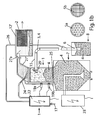
- FIG. 1a shows a compressed air conveying system for a bulk material, which is stored in a storage container 8 and to a consumer, in this case a granular dryer 7, must be promoted.
- a granulate is used, for example, for all bulk materials which can be conveyed and treated with this technology, without limiting the invention to this.
- an ejector suction lance 6 in the reservoir 8 for example, a big bag or an octabin, inserted in which a compressed air line 26 opens, the granules 4 from the reservoir 8 through the open opening in the suction lance into the connected to the lance conveyor line 15th get carried away.
- the delivery line 15 usually a flexible hose, conveys the bulk material over greater distances in the direction of the consumer, here the granular dryer 7, which is essentially an upright intermediate container, in the one heated by an air conditioner 23 and optionally dried drying air is introduced, which flows through the granules and thereby dried. From there, the granulate 4 runs in a further arranged below, not shown consumers, such as a plastic injection machine.
- the delivery line 15 does not open directly into the consumer, but in a mostly placed on it or at a distance above set granule in which the granules are separated from the conveying air again.
- the dense, upstanding cylinder of the granule has an upper outlet opening 18 for the conveying air and the dust compartment, which is in the conically upwardly tapered, on the cylindrical part tightly placed and removable cover 27.
- the lower end of the cylindrical granule separator serves as a granule collecting area and may be fully open at the bottom or taper downwardly, initially conically, to a lower granule outlet opening.
- the free end In between opens in a side wall of the granulate the conveyor line 15, the free end is here closed by a shutter which suspended in the pressureless state of the conveyor line 15 by gravity vertically and closes the vertical open end, but are pivoted about a horizontal axis above the feed line 15 can and then serves as a baffle plate for the granules, which shoots out of the opening.
- the sieve 5 is arranged in the granulate separator, which is just close-meshed enough to retain all the granulate particles, but allows the dust particles to pass easily in the direction of the outlet opening 18.
- the upper outlet port 18 is the only possible Outlet for the conveying air, since the Granulatauslassö réelle represents a much higher flow resistance due to the accumulated granules.
- the conveying air therefore leaves the separator almost completely via the upper outlet line 18 and also the dust content.
- one or more cleaning nozzles 24 are arranged above the screen, the control 22 are also acted upon with compressed air and with the help of which the deposits are shot at the screen, preferably while the conveying air is turned on to promote the screen-solving dust particles directly up to the outlet opening.
- the connected at the outlet opening 18 dust line 20 opens into a dust collector 12, the conveying air can leave only a particular arranged in the top of the sump 12 filter 2, which is so dense that it can not be penetrated by the dust particles 11.
- the dust is therefore deposited on the filter 2 and falls down to the bottom of the reservoir 12.
- compressed air source is usually present at the site compressed air network with usually 6 bar available, which is also connected to the controller 22, optionally also to the air conditioner 23 for the dryer. 7
- FIG. 1b differs from FIG. 1a in that the dust collecting container is not far away and connected via a mostly flexible dust line 20 to the granulate and also fixed mechanically fixed to the dust collector:
- the cover 27 'of the granule is equipped with a over the base of the granulate radially outwardly projecting proboscis 27 to which the reservoir 12' directly plugged with a corresponding inlet opening and thereby can be supported without a flexible tubing between the two is needed ,
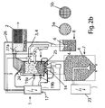
- FIGS. 2a and 2 B correspond to those of FIGS. 1a and 1b except for the additional second dedusting stage.
- the lower granule opening 25 in the granulate separator can be closed by a closure cone that can be tightly inserted from below into the granule opening 25, and the side walls of the granulate separator 1 taper toward the granule opening 25, tapering conically from top to bottom.
- compressed air nozzles 16a, b are arranged, which in turn with the controller 22 in connection stand and controlled by this injected compressed air into the deposited granules and thereby the granules in the separator 1 can again whirl confused.
- FIGS. 2a, b two opening into the granulate 1 conveyor lines 15a, b (which can promote material from different reservoirs 8) with a valve 28a, b closed to during the insertion of compressed air via the compressed air nozzles 16ab ... an intrusion of dust and granules in the feed line 15a to prevent b.
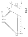
- FIG. 3 shows a like. B. in the FIG. 2a upwardly conically tapered cover 27 of the granule 1, at its highest point the outlet opening 18 is arranged for the air-dust mixture, and arranged below the lid in the cylindrical region of the screen fifth
- FIG. 3 is shown that the delivery line 15 by no means necessarily open into one of the side walls of the granulate, as in the FIGS. 1 and 2 shown, but instead also in the upper end face, so the lid can open.
- the delivery line 15 can be arranged in the cover in addition to the previously arranged centrally outlet opening 18 or for this purpose can - which is not shown - the outlet opening 18 also be replaced out of the center.
- the delivery line 15 must also penetrate the screen 5, which is too fine mesh to allow granules to pass.
- a closure element in the delivery line 15 can also be arranged in this case - if necessary - either inside or outside of the granulate.
- valves usually located outside the separator, are available as well as conventional closure elements, as well as sealing cones which can be placed on the free end of the mouth.
Claims (16)
- Installation d'alimentation en air comprimé avec un séparateur de granulé (1), une conduite d'alimentation (15) qui débouche dans le séparateur de granulé (1) pour la livraison de la matière en vrac et une conduite d'air comprimé (26) débouchant dans une lance d'aspiration d'éjecteur (6) et raccordée à la conduite d'alimentation (15), le séparateur de granulé (1) présentant- un filtre (2) qui peut être traversé par l'air d'alimentation (3) mais pas par la poussière, qui est disposé dans un récipient de collecte de poussière (12) séparément de la zone de collecte de granulé du séparateur de granulé (1) et- un tamis (5<9 disposé en amont du filtre (2) qui peut être traversé par l'air alimenté (3) et la poussière (11) et dont la trame est suffisamment serrée pour retenir toutes les particules de granules.
- Installation d'alimentation en air comprimé selon la revendication 1, caractérisée en ce que- le réservoir de collecte de poussière (12) est un réservoir séparé du séparateur de granulé et est un réservoir relié de manière hermétique avec cd dernier par une conduite de poussière (209, et
le récipient de collecte de poussière (12) présente un fond fermé (12a) sur lequel se rassemble la poussière tombant par exemple du filtre (2). - Installation d'alimentation en air comprimé selon l'une des revendications précédentes, caractérisée en ce que la zone de collecte de granulé présente une ouverture fermable de granulé (25) et des ouverture d'air comprimé débouchent dans la zone de sortie en particulier dans les parois latérales de la sortie et/ou de l'élément de fermeture, en particulier des buses d'air comprimé qui sont orientées en direction de l'intérieur de la zone de collecte de granulé.
- Installation d'alimentation en air comprimé selon l'une des revendications précédentes, caractérisée en ce que la conduite d'alimentation (15) présente une fermeture automatique.
- Installation d'alimentation en air comprimé selon l'une des revendications précédentes, caractérisée en ce que le filtre (2) est réalisé le plus possible largement surfacé et en particulier son contour externe remplit au moins 41 % au mieux au moins 50 %, au mieux 70 % de l'espace interne libre du récipient de collecte (12).
- Installation d'alimentation en air comprimé selon l'une des revendications précédentes, caractérisée en ce que- le récipient de collecte (12) est un fût en particulier un fût en matière pastique avec un couvercle étanche et le filtre (2) est fixé de manière étanche dans le couvercle par sa face supérieure et- la conduite de poussière (20) débouche en amont de l'extrémité inférieure du filtre dans la paroi latérale du filtre et une tôle déflectrice est disposé entre l'embouchure et le filtre.
- Installation d'alimentation en air comprimé selon l'une des revendications précédentes, caractérisée en ce que- la conduite de poussière (20) est une conduite flexible entre l'ouverture de sortie (18) et le récipient de collecte (12) et plusieurs conduites de poussière (20) sont raccordées au récipient collecteur (12) provenant de différents séparateurs de granulés, ou- le récipient de collecte de poussière (12) est raccordé par une tubulure de raccordement fixe à une ouverture de sortie (18) du séparateur et y est maintenu mécaniquement ou est réalisé d'une seule pièce ensemble avec au moins le couvercle du séparateur.
- Installation d'alimentation en air comprimé selon l'une des revendications précédentes, caractérisée en ce que l'ouverture de sortie (18) est disposée centralement dans la section supérieure du séparateur et la section transversale se réduite en particulier coniquement vers le haut en direction de l'ouverture de sortie (18).
- Installation d'alimentation en air comprimé selon l'une des revendications précédentes, caractérisée en ce que le tamis (5) présente un disque de tamis interchangeable et se trouve en dessous du couvercle amovible du séparateur dans lequel est disposée l'ouverture de sortie (18).
- Installation d'alimentation en air comprimé selon l'une des revendications précédentes, caractérisée en ce que les parois latérales du séparateur se composent au moins partiellement de verre ou de plastique et un capteur de niveau capacitif (19) est au moins disposé sur la paroi.
- Installation d'alimentation en air comprimé selon l'une des revendications précédentes, caractérisée en ce qu'au moins une buse d'éjecteur supplémentaire (21) est disposée au moins dans la conduite de poussière (20).
- Installation d'alimentation en air comprimé selon la revendication 4, caractérisée en ce que la fermeture dans la conduite de transport (15) est une vanne d'arrêt en particulier juste avant l'entrée de la conduite de transport (15) dans le séparateur.
- Installation d'alimentation en air comprimé selon l'une des revendications précédentes, caractérisée en ce que l'embouchure de la conduite de transport (15) débouche dans le couvercle (27) du séparateur de granulé et est dirigé en direction du fond du séparateur de granulé.
- Installation d'alimentation en air comprimé selon la revendication 4, caractérisée en ce que l'extrémité de la conduite de transport (15) est découpée en biseau, l'extrémité inférieure faisant saillie plus vers l'avant que l'extrémité avant et le capot de fermeture (29) étant orienté dans l'état fermé complètement de manière inclinée vers le haut en s'éloignant du point d'articulation de la conduite de transport (15) et sert de plaque déflectrice.
- Procédé pour le fractionnement de fractions de différentes granulométries en particulier de poussière et essentiellement de particules plus grossières dans une matière en vrac de granulé ou matière broyée d'autres part,- le mélange des deux fractions étant amené à un séparateur par un air de transport (3),- l'air de transport (3) s'échappant ensemble avec la fraction fine dans la zone supérieure du séparateur par une ouverture de sorite et étant amené à un récipient séparé de collecte (12) de poussière, tandis que les particules les plus grossières étant retenues par un tamis (5) fermant cette ouverture de sortie (18) d et se rassemblant dans la zone inférieure du séparateur de granulé par gravité,caractérisé en ce que
le mélange provenant des lances d'aspiration d'éjecteur (6) entraînées par air comprimé est alimenté au séparateur. - Procédé selon la revendication 15, caractérisé en ce que pendant ou après le transport, l'ouverture de sortie ainsi qu'éventuellement les conduites d'amenée sont fermées et de l'air de nettoyage est soufflé dans le granulé par le bas par des buses d'air comprimé (16a, b).
Applications Claiming Priority (2)
| Application Number | Priority Date | Filing Date | Title |
|---|---|---|---|
| DE200710047119 DE102007047119A1 (de) | 2007-10-02 | 2007-10-02 | Druckluftförderanlage für Schüttgut |
| DE200720013754 DE202007013754U1 (de) | 2007-10-02 | 2007-10-02 | Druckluftförderanlage für Schüttgut |
Publications (2)
| Publication Number | Publication Date |
|---|---|
| EP2045199A1 EP2045199A1 (fr) | 2009-04-08 |
| EP2045199B1 true EP2045199B1 (fr) | 2010-05-12 |
Family
ID=39885127
Family Applications (1)
| Application Number | Title | Priority Date | Filing Date |
|---|---|---|---|
| EP08165733A Active EP2045199B1 (fr) | 2007-10-02 | 2008-10-02 | Appareil à air comprimé pour alimenter en poudre ou en matériaux granulaires |
Country Status (3)
| Country | Link |
|---|---|
| EP (1) | EP2045199B1 (fr) |
| AT (1) | ATE467592T1 (fr) |
| DE (1) | DE502008000644D1 (fr) |
Cited By (2)
| Publication number | Priority date | Publication date | Assignee | Title |
|---|---|---|---|---|
| CN102351081A (zh) * | 2011-09-01 | 2012-02-15 | 中国上海外经(集团)有限公司 | 水泥筒仓相互回收装置及回收方法 |
| CN103043443A (zh) * | 2012-12-17 | 2013-04-17 | 天津英康科技发展有限公司 | 膨胀珍珠岩扒砂机及其工作方法 |
Families Citing this family (13)
| Publication number | Priority date | Publication date | Assignee | Title |
|---|---|---|---|---|
| WO2013057379A1 (fr) * | 2011-10-19 | 2013-04-25 | Baudelaire Elie | Procede ptc pour l'extraction par voie seche des principes actifs naturels |
| EP2607274B1 (fr) * | 2011-12-21 | 2014-08-13 | Klaus Wilhelm | Séparateur pour granules et installation d'alimentation en air comprimé avec séparateur pour granules |
| CN102992037A (zh) * | 2012-12-19 | 2013-03-27 | 陆俊 | 一种防尘挤塑机上料设备 |
| CN104555446A (zh) * | 2014-12-08 | 2015-04-29 | 桐乡市中辰化纤有限公司 | 聚酯配料的二氧化钛加料装置 |
| CN104609219A (zh) * | 2015-02-04 | 2015-05-13 | 中交一航局安装工程有限公司 | 一种储煤筒仓群除尘连通装置 |
| CN104826796B (zh) * | 2015-05-11 | 2016-09-14 | 湖州睿高新材料有限公司 | 一种粉末阻燃剂改进设备的除杂装置 |
| CN104891186A (zh) * | 2015-06-22 | 2015-09-09 | 丁巧娜 | 一种防滑设置的吸谷机 |
| CN105197598A (zh) * | 2015-09-15 | 2015-12-30 | 山东省农业机械科学研究院 | 真空提升机 |
| CN106348021A (zh) * | 2016-10-13 | 2017-01-25 | 天津市职业大学 | 粉料和颗粒料通用真空输送仿真试验机 |
| EP3530599A1 (fr) * | 2018-02-27 | 2019-08-28 | Piab Ab | Système de transporteur à vide |
| DE102018124207B4 (de) * | 2018-10-01 | 2022-07-14 | Klaus Wilhelm | Vorrichtung und Verfahren zum Entstauben von Schüttgütern |
| WO2023283625A1 (fr) * | 2021-07-08 | 2023-01-12 | Industrial Vacuum Transfer Services Usa, Llc | Ensembles, appareils, systèmes et procédés d'extraction et de transport de matériau |
| CN114194833B (zh) * | 2021-12-08 | 2023-08-22 | 晋江力绿食品有限公司 | 海苔膨化食品生产用真空送料系统 |
Family Cites Families (23)
| Publication number | Priority date | Publication date | Assignee | Title |
|---|---|---|---|---|
| DE489542C (de) * | 1926-12-12 | 1930-01-17 | Johann Carl Mueller Fa | Vorrichtung zum Entfernen des Staubes aus geschnittenem Tabak |
| GB750830A (en) * | 1954-01-26 | 1956-06-20 | Buehler Ag Geb | Improvements in or relating to pneumatic conveying installations |
| US3685651A (en) * | 1969-12-18 | 1972-08-22 | Clarence R Gruber | Particle cleaning apparatus |
| DE2058605A1 (de) * | 1970-11-28 | 1972-06-22 | Single Thermogeraetebau Gmbh & | Geraet zur Behandlung schuettbarer Gueter |
| CH598100A5 (fr) * | 1975-02-13 | 1978-04-28 | Waeschle Maschf Gmbh | |
| DE2625734A1 (de) * | 1976-06-09 | 1977-12-22 | Motan Gmbh | Abscheider fuer saugfoerdergeraete, insbesondere fuer pulverartiges transportgut |
| DE3223073A1 (de) | 1982-06-21 | 1984-03-08 | M&S Industriebedarf GmbH, 5511 Ayl | Pneumatische entstaubungs- und foerderanlage |
| DE3327208A1 (de) * | 1983-03-10 | 1984-09-13 | Basf Farben + Fasern Ag, 2000 Hamburg | Verfahren und vorrichtung zum foerdern von pulverfoermigen schuettguetern |
| DE3327461A1 (de) * | 1983-07-29 | 1985-02-14 | Waeschle Maschinenfabrik Gmbh, 7980 Ravensburg | Abscheider fuer pneumatisch gefoerdertes schuettgut |
| DE3409814A1 (de) * | 1984-03-16 | 1985-09-19 | Waeschle Maschinenfabrik Gmbh, 7980 Ravensburg | Gegenstromsichter |
| DE3502448A1 (de) * | 1985-01-25 | 1986-07-31 | Robert Bosch Gmbh, 7000 Stuttgart | Vorrichtung zum entfernen von russpartikeln und anderen festkoerperteilchen aus dem abgas von kraftfahrzeugen |
| US4699710A (en) * | 1985-02-26 | 1987-10-13 | Williams Paul J | Separator for particulates |
| DE3878072D1 (de) * | 1987-07-29 | 1993-03-18 | Bat Cigarettenfab Gmbh | Abscheider zur trennung von tabak-teilchen aus einem tabak/gas-gemisch. |
| EP0528755A1 (fr) * | 1991-08-16 | 1993-02-24 | Siegfried Frei | Dispositif d'aspiration de matières pulvérulantes |
| DE4134824A1 (de) * | 1991-10-22 | 1993-04-29 | Battenfeld Kunststoffmasch | Vorrichtung zur foerderung von koernigen und/oder pulvrigen feststoffen |
| DE4410087C2 (de) * | 1994-03-24 | 1997-08-07 | Mann & Hummel Filter | Verschluß für ein im Unterdruck arbeitendes Fördergerät |
| DE59610421D1 (de) * | 1995-12-29 | 2003-06-12 | Glatt Gmbh | Einrichtung zum Entstauben von Gas |
| DE29806011U1 (de) * | 1998-04-02 | 1998-07-16 | I S I S Ingenieur Seminar Fuer | Saugsilo für bindige Schüttgüter |
| DE10033837C1 (de) * | 2000-07-12 | 2001-10-31 | Nikolaus Wilhelm | Druckluftfördergerät für Schüttgüter |
| AT6151U1 (de) * | 2002-05-23 | 2003-05-26 | Leitl Tank Ges M B H & Co Kg | Saugfördereinrichtung |
| JP4315905B2 (ja) * | 2002-09-24 | 2009-08-19 | 株式会社菊水製作所 | 粒体の粉取り兼垂直搬送兼集塵の方法及び装置 |
| DE102004015014A1 (de) | 2004-03-26 | 2005-10-13 | HELIOS Gerätebau für Kunststofftechnik GmbH | Verfahren und Vorrichtung zum Entleeren von Schüttgut |
| DE102006005209A1 (de) * | 2006-02-06 | 2007-08-09 | Nordson Corp., Westlake | Sauglanze, Vorrichtung und Verfahren zum Fördern von pulverförmigem Material zu einer Dichtstrompumpe |
-
2008
- 2008-10-02 EP EP08165733A patent/EP2045199B1/fr active Active
- 2008-10-02 DE DE502008000644T patent/DE502008000644D1/de active Active
- 2008-10-02 AT AT08165733T patent/ATE467592T1/de active
Cited By (3)
| Publication number | Priority date | Publication date | Assignee | Title |
|---|---|---|---|---|
| CN102351081A (zh) * | 2011-09-01 | 2012-02-15 | 中国上海外经(集团)有限公司 | 水泥筒仓相互回收装置及回收方法 |
| CN102351081B (zh) * | 2011-09-01 | 2013-05-01 | 中国上海外经(集团)有限公司 | 水泥筒仓相互回收装置及回收方法 |
| CN103043443A (zh) * | 2012-12-17 | 2013-04-17 | 天津英康科技发展有限公司 | 膨胀珍珠岩扒砂机及其工作方法 |
Also Published As
| Publication number | Publication date |
|---|---|
| ATE467592T1 (de) | 2010-05-15 |
| EP2045199A1 (fr) | 2009-04-08 |
| DE502008000644D1 (de) | 2010-06-24 |
Similar Documents
| Publication | Publication Date | Title |
|---|---|---|
| EP2045199B1 (fr) | Appareil à air comprimé pour alimenter en poudre ou en matériaux granulaires | |
| EP1953098B1 (fr) | Dispositif de vidange pour sacs de poudre pour installations de revêtement par poudre vaporisée | |
| DE102007005312A1 (de) | Pulverrückgewinnungsvorrichtung für eine Pulversprühbeschichtungsanlage | |
| DE102018124207B4 (de) | Vorrichtung und Verfahren zum Entstauben von Schüttgütern | |
| DE102007005310A1 (de) | Beschichtungspulver-Filtervorrichtung | |
| DE102012108907B4 (de) | Verfahren und Vorrichtung zum Entstauben von Schüttgütern mittels Ionisierung | |
| EP2045003A1 (fr) | Dispositif de transport et de mélange de produits en vrac | |
| DE102007047119A1 (de) | Druckluftförderanlage für Schüttgut | |
| EP0202356B1 (fr) | Dispositif de transport | |
| EP2607274B1 (fr) | Séparateur pour granules et installation d'alimentation en air comprimé avec séparateur pour granules | |
| DE102007005306A1 (de) | Pulverzufuhrvorrichtung von einer Pulversprühbeschichtungsanlage | |
| DE3900664C2 (fr) | ||
| EP1427657B1 (fr) | Dispositif et procede pour transporter un produit a transporter de type poussiere, poudre, grains ou granules, d'un recipient de stockage dans un recipient de travail ou de transport ou dans un espace de reception de meme type | |
| DE102009015271B4 (de) | Bearbeitungseinrichtung für Schüttgut | |
| DE202007013754U1 (de) | Druckluftförderanlage für Schüttgut | |
| DE3924566A1 (de) | Vorrichtung zum ausscheiden von metallteilchen aus rieselfaehigen schuettguetern (metallseparator) | |
| DE102014113280B4 (de) | Vorrichtung und Verfahren zum chargenweisen Entfernen von Staub aus einem Granulat | |
| EP2241867B1 (fr) | Dispositif et agencement destinés au remplissage de postes de traitement | |
| WO2009046478A1 (fr) | Séparateur de matériau pour systèmes de transport | |
| DE102008056369A1 (de) | Zyklonabscheider und Pulverrückgewinnungsvorrichtung für eine Pulverbeschichtungsanlage mit einem Zyklonabscheider | |
| DE102020107898B4 (de) | Wechsel-Adapter, Handhabungs-Einheit mit Wechseladapter, Verfahren zum Betreiben einer solchen Handhabungs- Einheit | |
| DE102019118093A1 (de) | Vorrichtung, Baukasten und Verfahren zum Behandeln von Schüttgütern | |
| DE102012224054A1 (de) | Vorrichtung zum Befördern eines Betriebsstoffes | |
| DE19811132C2 (de) | Vorrichtung zum Abscheiden feiner Partikel aus einem grobe und feine Partikel enthaltenden, mittels eines Gasstroms geförderten Schüttgutstrom | |
| DE202011052400U1 (de) | Druckluftförderanlage für Schüttgut |
Legal Events
| Date | Code | Title | Description |
|---|---|---|---|
| PUAI | Public reference made under article 153(3) epc to a published international application that has entered the european phase |
Free format text: ORIGINAL CODE: 0009012 |
|
| AK | Designated contracting states |
Kind code of ref document: A1 Designated state(s): AT BE BG CH CY CZ DE DK EE ES FI FR GB GR HR HU IE IS IT LI LT LU LV MC MT NL NO PL PT RO SE SI SK TR |
|
| AX | Request for extension of the european patent |
Extension state: AL BA MK RS |
|
| 17P | Request for examination filed |
Effective date: 20090424 |
|
| 17Q | First examination report despatched |
Effective date: 20090626 |
|
| GRAP | Despatch of communication of intention to grant a patent |
Free format text: ORIGINAL CODE: EPIDOSNIGR1 |
|
| AKX | Designation fees paid |
Designated state(s): AT BE BG CH CY CZ DE DK EE ES FI FR GB GR HR HU IE IS IT LI LT LU LV MC MT NL NO PL PT RO SE SI SK TR |
|
| GRAS | Grant fee paid |
Free format text: ORIGINAL CODE: EPIDOSNIGR3 |
|
| GRAA | (expected) grant |
Free format text: ORIGINAL CODE: 0009210 |
|
| AK | Designated contracting states |
Kind code of ref document: B1 Designated state(s): AT BE BG CH CY CZ DE DK EE ES FI FR GB GR HR HU IE IS IT LI LT LU LV MC MT NL NO PL PT RO SE SI SK TR |
|
| REG | Reference to a national code |
Ref country code: GB Ref legal event code: FG4D Free format text: NOT ENGLISH |
|
| REG | Reference to a national code |
Ref country code: CH Ref legal event code: EP |
|
| REG | Reference to a national code |
Ref country code: IE Ref legal event code: FG4D Free format text: LANGUAGE OF EP DOCUMENT: GERMAN |
|
| REF | Corresponds to: |
Ref document number: 502008000644 Country of ref document: DE Date of ref document: 20100624 Kind code of ref document: P |
|
| REG | Reference to a national code |
Ref country code: NL Ref legal event code: VDEP Effective date: 20100512 |
|
| LTIE | Lt: invalidation of european patent or patent extension |
Effective date: 20100512 |
|
| PG25 | Lapsed in a contracting state [announced via postgrant information from national office to epo] |
Ref country code: ES Free format text: LAPSE BECAUSE OF FAILURE TO SUBMIT A TRANSLATION OF THE DESCRIPTION OR TO PAY THE FEE WITHIN THE PRESCRIBED TIME-LIMIT Effective date: 20100823 Ref country code: LT Free format text: LAPSE BECAUSE OF FAILURE TO SUBMIT A TRANSLATION OF THE DESCRIPTION OR TO PAY THE FEE WITHIN THE PRESCRIBED TIME-LIMIT Effective date: 20100512 Ref country code: NL Free format text: LAPSE BECAUSE OF FAILURE TO SUBMIT A TRANSLATION OF THE DESCRIPTION OR TO PAY THE FEE WITHIN THE PRESCRIBED TIME-LIMIT Effective date: 20100512 Ref country code: NO Free format text: LAPSE BECAUSE OF FAILURE TO SUBMIT A TRANSLATION OF THE DESCRIPTION OR TO PAY THE FEE WITHIN THE PRESCRIBED TIME-LIMIT Effective date: 20100812 Ref country code: SE Free format text: LAPSE BECAUSE OF FAILURE TO SUBMIT A TRANSLATION OF THE DESCRIPTION OR TO PAY THE FEE WITHIN THE PRESCRIBED TIME-LIMIT Effective date: 20100512 |
|
| PG25 | Lapsed in a contracting state [announced via postgrant information from national office to epo] |
Ref country code: SI Free format text: LAPSE BECAUSE OF FAILURE TO SUBMIT A TRANSLATION OF THE DESCRIPTION OR TO PAY THE FEE WITHIN THE PRESCRIBED TIME-LIMIT Effective date: 20100512 Ref country code: LV Free format text: LAPSE BECAUSE OF FAILURE TO SUBMIT A TRANSLATION OF THE DESCRIPTION OR TO PAY THE FEE WITHIN THE PRESCRIBED TIME-LIMIT Effective date: 20100512 Ref country code: IS Free format text: LAPSE BECAUSE OF FAILURE TO SUBMIT A TRANSLATION OF THE DESCRIPTION OR TO PAY THE FEE WITHIN THE PRESCRIBED TIME-LIMIT Effective date: 20100912 Ref country code: HR Free format text: LAPSE BECAUSE OF FAILURE TO SUBMIT A TRANSLATION OF THE DESCRIPTION OR TO PAY THE FEE WITHIN THE PRESCRIBED TIME-LIMIT Effective date: 20100512 Ref country code: FI Free format text: LAPSE BECAUSE OF FAILURE TO SUBMIT A TRANSLATION OF THE DESCRIPTION OR TO PAY THE FEE WITHIN THE PRESCRIBED TIME-LIMIT Effective date: 20100512 |
|
| REG | Reference to a national code |
Ref country code: IE Ref legal event code: FD4D |
|
| PG25 | Lapsed in a contracting state [announced via postgrant information from national office to epo] |
Ref country code: CY Free format text: LAPSE BECAUSE OF FAILURE TO SUBMIT A TRANSLATION OF THE DESCRIPTION OR TO PAY THE FEE WITHIN THE PRESCRIBED TIME-LIMIT Effective date: 20100609 Ref country code: PL Free format text: LAPSE BECAUSE OF FAILURE TO SUBMIT A TRANSLATION OF THE DESCRIPTION OR TO PAY THE FEE WITHIN THE PRESCRIBED TIME-LIMIT Effective date: 20100512 |
|
| PG25 | Lapsed in a contracting state [announced via postgrant information from national office to epo] |
Ref country code: IE Free format text: LAPSE BECAUSE OF FAILURE TO SUBMIT A TRANSLATION OF THE DESCRIPTION OR TO PAY THE FEE WITHIN THE PRESCRIBED TIME-LIMIT Effective date: 20100512 Ref country code: EE Free format text: LAPSE BECAUSE OF FAILURE TO SUBMIT A TRANSLATION OF THE DESCRIPTION OR TO PAY THE FEE WITHIN THE PRESCRIBED TIME-LIMIT Effective date: 20100512 Ref country code: DK Free format text: LAPSE BECAUSE OF FAILURE TO SUBMIT A TRANSLATION OF THE DESCRIPTION OR TO PAY THE FEE WITHIN THE PRESCRIBED TIME-LIMIT Effective date: 20100512 |
|
| PGFP | Annual fee paid to national office [announced via postgrant information from national office to epo] |
Ref country code: FR Payment date: 20101109 Year of fee payment: 3 |
|
| PG25 | Lapsed in a contracting state [announced via postgrant information from national office to epo] |
Ref country code: CZ Free format text: LAPSE BECAUSE OF FAILURE TO SUBMIT A TRANSLATION OF THE DESCRIPTION OR TO PAY THE FEE WITHIN THE PRESCRIBED TIME-LIMIT Effective date: 20100512 Ref country code: RO Free format text: LAPSE BECAUSE OF FAILURE TO SUBMIT A TRANSLATION OF THE DESCRIPTION OR TO PAY THE FEE WITHIN THE PRESCRIBED TIME-LIMIT Effective date: 20100512 Ref country code: SK Free format text: LAPSE BECAUSE OF FAILURE TO SUBMIT A TRANSLATION OF THE DESCRIPTION OR TO PAY THE FEE WITHIN THE PRESCRIBED TIME-LIMIT Effective date: 20100512 |
|
| PLBE | No opposition filed within time limit |
Free format text: ORIGINAL CODE: 0009261 |
|
| STAA | Information on the status of an ep patent application or granted ep patent |
Free format text: STATUS: NO OPPOSITION FILED WITHIN TIME LIMIT |
|
| 26N | No opposition filed |
Effective date: 20110215 |
|
| BERE | Be: lapsed |
Owner name: WILHELM, KLAUS Effective date: 20101031 |
|
| PG25 | Lapsed in a contracting state [announced via postgrant information from national office to epo] |
Ref country code: MC Free format text: LAPSE BECAUSE OF NON-PAYMENT OF DUE FEES Effective date: 20101031 Ref country code: GR Free format text: LAPSE BECAUSE OF FAILURE TO SUBMIT A TRANSLATION OF THE DESCRIPTION OR TO PAY THE FEE WITHIN THE PRESCRIBED TIME-LIMIT Effective date: 20100813 |
|
| REG | Reference to a national code |
Ref country code: DE Ref legal event code: R097 Ref document number: 502008000644 Country of ref document: DE Effective date: 20110214 |
|
| PG25 | Lapsed in a contracting state [announced via postgrant information from national office to epo] |
Ref country code: BE Free format text: LAPSE BECAUSE OF NON-PAYMENT OF DUE FEES Effective date: 20101031 |
|
| PG25 | Lapsed in a contracting state [announced via postgrant information from national office to epo] |
Ref country code: MT Free format text: LAPSE BECAUSE OF FAILURE TO SUBMIT A TRANSLATION OF THE DESCRIPTION OR TO PAY THE FEE WITHIN THE PRESCRIBED TIME-LIMIT Effective date: 20100512 |
|
| REG | Reference to a national code |
Ref country code: FR Ref legal event code: ST Effective date: 20120629 |
|
| PG25 | Lapsed in a contracting state [announced via postgrant information from national office to epo] |
Ref country code: FR Free format text: LAPSE BECAUSE OF NON-PAYMENT OF DUE FEES Effective date: 20111102 |
|
| PG25 | Lapsed in a contracting state [announced via postgrant information from national office to epo] |
Ref country code: HU Free format text: LAPSE BECAUSE OF FAILURE TO SUBMIT A TRANSLATION OF THE DESCRIPTION OR TO PAY THE FEE WITHIN THE PRESCRIBED TIME-LIMIT Effective date: 20101113 Ref country code: LU Free format text: LAPSE BECAUSE OF NON-PAYMENT OF DUE FEES Effective date: 20101002 Ref country code: BG Free format text: LAPSE BECAUSE OF FAILURE TO SUBMIT A TRANSLATION OF THE DESCRIPTION OR TO PAY THE FEE WITHIN THE PRESCRIBED TIME-LIMIT Effective date: 20100512 |
|
| PG25 | Lapsed in a contracting state [announced via postgrant information from national office to epo] |
Ref country code: TR Free format text: LAPSE BECAUSE OF FAILURE TO SUBMIT A TRANSLATION OF THE DESCRIPTION OR TO PAY THE FEE WITHIN THE PRESCRIBED TIME-LIMIT Effective date: 20100512 |
|
| PG25 | Lapsed in a contracting state [announced via postgrant information from national office to epo] |
Ref country code: PT Free format text: LAPSE BECAUSE OF NON-PAYMENT OF DUE FEES Effective date: 20100512 |
|
| PG25 | Lapsed in a contracting state [announced via postgrant information from national office to epo] |
Ref country code: BG Free format text: LAPSE BECAUSE OF FAILURE TO SUBMIT A TRANSLATION OF THE DESCRIPTION OR TO PAY THE FEE WITHIN THE PRESCRIBED TIME-LIMIT Effective date: 20100812 |
|
| PGFP | Annual fee paid to national office [announced via postgrant information from national office to epo] |
Ref country code: GB Payment date: 20201022 Year of fee payment: 13 |
|
| PGFP | Annual fee paid to national office [announced via postgrant information from national office to epo] |
Ref country code: CH Payment date: 20211020 Year of fee payment: 14 |
|
| GBPC | Gb: european patent ceased through non-payment of renewal fee |
Effective date: 20211002 |
|
| PG25 | Lapsed in a contracting state [announced via postgrant information from national office to epo] |
Ref country code: GB Free format text: LAPSE BECAUSE OF NON-PAYMENT OF DUE FEES Effective date: 20211002 |
|
| PGFP | Annual fee paid to national office [announced via postgrant information from national office to epo] |
Ref country code: IT Payment date: 20221026 Year of fee payment: 15 |
|
| REG | Reference to a national code |
Ref country code: CH Ref legal event code: PL |
|
| PG25 | Lapsed in a contracting state [announced via postgrant information from national office to epo] |
Ref country code: LI Free format text: LAPSE BECAUSE OF NON-PAYMENT OF DUE FEES Effective date: 20221031 Ref country code: CH Free format text: LAPSE BECAUSE OF NON-PAYMENT OF DUE FEES Effective date: 20221031 |
|
| REG | Reference to a national code |
Ref country code: AT Ref legal event code: PC Ref document number: 467592 Country of ref document: AT Kind code of ref document: T Owner name: HELIOS GERAETEBAU FUER KUNSTSTOFFTECHNIK GMBH, DE Effective date: 20230829 |
|
| PGFP | Annual fee paid to national office [announced via postgrant information from national office to epo] |
Ref country code: DE Payment date: 20230929 Year of fee payment: 16 |
|
| PGFP | Annual fee paid to national office [announced via postgrant information from national office to epo] |
Ref country code: AT Payment date: 20240122 Year of fee payment: 16 |