EP2040868B2 - Machine-outil portative, en particulier scie manuelle - Google Patents
Machine-outil portative, en particulier scie manuelle Download PDFInfo
- Publication number
- EP2040868B2 EP2040868B2 EP07728898.3A EP07728898A EP2040868B2 EP 2040868 B2 EP2040868 B2 EP 2040868B2 EP 07728898 A EP07728898 A EP 07728898A EP 2040868 B2 EP2040868 B2 EP 2040868B2
- Authority
- EP
- European Patent Office
- Prior art keywords
- housing
- transmission
- power tool
- portable power
- tool according
- Prior art date
- Legal status (The legal status is an assumption and is not a legal conclusion. Google has not performed a legal analysis and makes no representation as to the accuracy of the status listed.)
- Active
Links
- 230000005540 biological transmission Effects 0.000 claims description 33
- 230000033001 locomotion Effects 0.000 claims description 28
- 229920003023 plastic Polymers 0.000 claims description 8
- 239000004033 plastic Substances 0.000 claims description 8
- 229920002457 flexible plastic Polymers 0.000 claims description 4
- 239000000463 material Substances 0.000 claims description 4
- 229910052751 metal Inorganic materials 0.000 claims description 4
- 239000002184 metal Substances 0.000 claims description 4
- 238000012544 monitoring process Methods 0.000 claims description 3
- 230000006378 damage Effects 0.000 description 5
- 238000005452 bending Methods 0.000 description 4
- 238000012806 monitoring device Methods 0.000 description 4
- 230000035939 shock Effects 0.000 description 2
- 240000001592 Amaranthus caudatus Species 0.000 description 1
- 235000009328 Amaranthus caudatus Nutrition 0.000 description 1
- HBBGRARXTFLTSG-UHFFFAOYSA-N Lithium ion Chemical compound [Li+] HBBGRARXTFLTSG-UHFFFAOYSA-N 0.000 description 1
- 229910052782 aluminium Inorganic materials 0.000 description 1
- XAGFODPZIPBFFR-UHFFFAOYSA-N aluminium Chemical compound [Al] XAGFODPZIPBFFR-UHFFFAOYSA-N 0.000 description 1
- 230000002457 bidirectional effect Effects 0.000 description 1
- 238000007664 blowing Methods 0.000 description 1
- 238000001816 cooling Methods 0.000 description 1
- 230000017525 heat dissipation Effects 0.000 description 1
- 238000009434 installation Methods 0.000 description 1
- 229910001416 lithium ion Inorganic materials 0.000 description 1
- 239000002245 particle Substances 0.000 description 1
- 238000010791 quenching Methods 0.000 description 1
- 230000000171 quenching effect Effects 0.000 description 1
Images


Classifications
-
- B—PERFORMING OPERATIONS; TRANSPORTING
- B23—MACHINE TOOLS; METAL-WORKING NOT OTHERWISE PROVIDED FOR
- B23D—PLANING; SLOTTING; SHEARING; BROACHING; SAWING; FILING; SCRAPING; LIKE OPERATIONS FOR WORKING METAL BY REMOVING MATERIAL, NOT OTHERWISE PROVIDED FOR
- B23D49/00—Machines or devices for sawing with straight reciprocating saw blades, e.g. hacksaws
- B23D49/10—Hand-held or hand-operated sawing devices with straight saw blades
- B23D49/16—Hand-held or hand-operated sawing devices with straight saw blades actuated by electric or magnetic power or prime movers
- B23D49/162—Pad sawing devices
-
- B—PERFORMING OPERATIONS; TRANSPORTING
- B23—MACHINE TOOLS; METAL-WORKING NOT OTHERWISE PROVIDED FOR
- B23D—PLANING; SLOTTING; SHEARING; BROACHING; SAWING; FILING; SCRAPING; LIKE OPERATIONS FOR WORKING METAL BY REMOVING MATERIAL, NOT OTHERWISE PROVIDED FOR
- B23D51/00—Sawing machines or sawing devices working with straight blades, characterised only by constructional features of particular parts; Carrying or attaching means for tools, covered by this subclass, which are connected to a carrier at both ends
- B23D51/16—Sawing machines or sawing devices working with straight blades, characterised only by constructional features of particular parts; Carrying or attaching means for tools, covered by this subclass, which are connected to a carrier at both ends of drives or feed mechanisms for straight tools, e.g. saw blades, or bows
Definitions
- the invention relates to a hand tool, in particular a hand saw, according to the preamble of claim 1.
- the housing consists of plastic.
- the gearbox and the motion converter are mechanically connected to each other. Only the motion converter is contained in a separate housing, which may consist of plastic or metal and in turn is received in a chamber formed within the plastic housing.
- the gearbox is also located in the same chamber of the plastic housing. However, since this is not placed within the housing of the motion converter, the transmission is directly exposed to shocks and shocks that can act in this area on the plastic housing.
- the hand tool according to the invention in particular hand saw, with the features of claim 1 has the advantage that they are small, handy and above all robust and is designed easily.
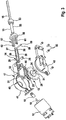
- a rib body is arranged on the housing shell of the gear housing in the region below the motion converter, which is designed as a heat sink and bending and torsion-resistant support for a foot plate and integral with the housing shell of the transmission housing.
- the housing made of flexible plastic is also able to absorb forces when hitting or dropping the power tool without the risk of damage or destruction.
- This plastic material design which is flexible, is possible due to the compact design and the fact that the gear unit, to which the transmission and the motion converter are combined, is included in the robust, bending and torsion-resistant gearbox made of metal.
- the plastic housing made of flexible Kunststofflst is able to absorb the eventual fall of the power tool forces. The power tool is protected in this way to a high degree against damage when dropped even from a great height.
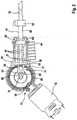
- FIG. 1 an electrical hand tool 10 is shown, which is designed as a small, handy and robust hand saw, which is designed as a foxtail about.
- This hand tool 10 has, within a housing 11, an electric drive motor 12, a drive 13 downstream of the drive motor 13 and a motion converter 14.
- the motion converter 14 By means of the motion converter 14, the output rotational movement of the transmission 13 is converted into an axially reciprocating working movement of a lifting element 15 for driving a tool 16, in particular a saw blade.
- the transmission 13 and the motion converter 14 form a drive train and are combined to form a transmission unit 17.
- the transmission 13 is designed as an angle gear. It has an output gear 18, which is pressed onto the motor shaft 19, and crown gear 20, with which the output gear 18 is meshed with the gear. By means of this transmission 13, the output speed of the drive motor 12 is reduced to a lower speed of the crown gear 20.
- the crown gear 20 has a pressed-in bearing pin 21 which projects to one side of the crown gear 20 and by means of at least one groove bearing, preferably by means of two axially adjacent groove bearing 22, 23, is mounted. In this way, the crown gear 20 is cantilevered.
- the crown gear 20 On the side opposite the groove bearings 22, 23, the crown gear 20 carries an eccentrically arranged, pressed-in bolt 24, which engages in a sleeve 25 at a facing end of a connecting rod 26 of the motion converter 14.
- the reciprocating element 15, which can be driven reciprocally by the motion converter 14, is designed as a rod 55 which protrudes from the transmission housing 40.
- a sliding bearing 56 is arranged, in which the lifting element 15, in particular in the form of the rod 55, mounted and guided displaceably back and forth.
- the sliding bearing 56 is received non-rotatably between the housing shell 41 and the housing cover 42 and penetrated by the facing end of the lifting element 15, in particular the rod 55.
- the arrangement is further made such that effective guide means for guiding the lifting element 15 are provided between the sliding bearing 56 and the lifting element 15, in particular the rod 55.
- These guide means may be formed from a non-circular and / or angular cross-sectional shape of the lifting element 15 and the bore of the sliding bearing 56 penetrated therefrom.
- the at least one connecting element 58 consists, for example, in a simple manner of a transverse pin 59 which engages the end of the connecting rod 26 facing away from the transmission 13 and the end of the lifting element 15 facing the connecting rod 26, eg in a fork receiving the eye 30 at the end of the lifting element 15 provided holes 60 traversed transversely.
- the longitudinal guides 57 are from the sliding bearing 56 in the direction of the connecting rod 26 which extends therebetween.
- the longitudinal guides 57 of the sliding bearing 56 have approximately parallel guide pins 61 on one side and 62 on the other side of the connecting rod 26, of which three guide pins can be provided on each side, for example.
- the hand tool 10 is powered by at least one battery or preferably at least one battery, which is shown only schematically and designated 64.
- This at least one battery 64 is a lithium-ion (Lilon) cell for feeding the drive motor 12.
- the housing 11 has a first portion 65 serving as a grip part and a second portion 66 connected integrally and inclined at an obtuse angle to the first portion 65.
- the at least one rechargeable battery 64 and also the electric drive motor 12 are accommodated in the first section 65, while in the second section 66 the gear housing 40 with the contained gear unit 17 are contained.
Landscapes
- Engineering & Computer Science (AREA)
- Mechanical Engineering (AREA)
- Sawing (AREA)
- Connection Of Motors, Electrical Generators, Mechanical Devices, And The Like (AREA)
- Transmission Devices (AREA)
- Portable Power Tools In General (AREA)
Claims (14)
- Machine-outil portative, en particulier scie manuelle, qui comprend à l'intérieur d'un boîtier (11) en plastique un moteur d'entraînement électrique (12), une transmission (13) montée en aval de celui-ci et un convertisseur de mouvement (14) qui convertit le mouvement de sortie rotatif de la transmission (13) en un mouvement de travail axialement alternatif d'un élément de course (15) pour l'entraînement d'un outil (16), en particulier d'une lame de scie, l'unité de transmission (17), en laquelle sont réunis la transmission (13) et le convertisseur de mouvement (14), étant disposée à l'intérieur d'un boîtier de transmission (40) en métal robuste et rigide à la flexion et à la torsion, lequel boîtier de transmission est quant à lui reçu dans le boîtier (11), le boîtier de transmission (40) étant en deux parties et étant constitué d'une enveloppe de boîtier (41) et d'un couvercle de boîtier (42) recouvrant l'enveloppe de boîtier (41), lequel est relié de manière amovible à l'enveloppe de boîtier (41), et le boîtier (11) étant formé à partir de plastique flexible, caractérisée en ce qu'un corps à ailettes (44) est disposé sur l'enveloppe de boîtier (41) du boîtier de transmission (40) dans la région du côté inférieur du convertisseur de mouvement (14), lequel corps à ailettes est réalisé en tant que corps de refroidissement et support rigide à la flexion et à la torsion pour une plaque de base (45) et fait corps avec l'enveloppe de boîtier (41) du boîtier de transmission (40).
- Machine-outil portative selon la revendication 1, caractérisée en ce que latéralement à proximité de l'unité de transmission (17), en particulier sur le côté extérieur du couvercle de boîtier (42), est disposé un commutateur électrique (47) dont l'organe d'actionnement (48) est accouplé à un actionneur (49), par exemple un poussoir basculant, faisant saillie hors du boîtier (11).
- Machine-outil portative selon la revendication 2, caractérisée en ce que l'actionneur (49), par exemple le poussoir basculant, est disposé de manière décalée transversalement par rapport à un plan de joint du moule (35) de deux enveloppes de boîtier (33, 34) formant conjointement le boîtier (11).
- Machine-outil portative selon l'une quelconque des revendications 1 à 3, caractérisée en ce qu'un dispositif de contrôle électronique (51) pour le contrôle de la consommation de courant est disposé latéralement à proximité de l'unité de transmission (17), en particulier sur le côté extérieur du couvercle de boîtier (42).
- Machine-outil portative selon l'une quelconque des revendications 1 à 4, caractérisée en ce que la transmission (13) comprend une couronne dentée (20) s'engrenant avec un pignon de sortie (18) du moteur d'entraînement (12), laquelle couronne dentée est dotée d'un boulon de palier (21), faisant saillie d'un côté, qui est monté dans le boîtier de transmission (40), en particulier dans son enveloppe de boîtier (41), au moyen d'au moins un palier rainuré, de préférence au moyen de deux paliers rainurés (22, 23) axialement adjacents.
- Machine-outil portative selon l'une quelconque des revendications 1 à 5, caractérisée en ce que la transmission (13) comprend une roue de ventilateur (36) entraînée par celle-ci.
- Machine-outil portative selon la revendication 6, caractérisée en ce que la roue de ventilateur (36) est disposée sur le boulon de palier (21) de la couronne dentée (20).
- Machine-outil portative selon l'une quelconque des revendications 1 à 7, caractérisée en ce qu'un palier lisse (56) est disposé dans le boîtier de transmission (40), l'élément de course (15) étant monté et guidé dans ce palier lisse de manière à pouvoir être animé d'un mouvement alternatif.
- Machine-outil portative selon la revendication 8, caractérisée par des moyens de guidage opérant entre le palier lisse (56) et l'élément de course (15).
- Machine-outil portative selon la revendication 9, caractérisée en ce que les moyens de guidage sont formés à partir de guides longitudinaux (57) sur le palier lisse (56), lesquels font saillie de celui-ci, et à partir d'au moins un élément de liaison (58) s'engageant avec l'élément de course (15), au moyen duquel élément de liaison le convertisseur de mouvement (14) est relié à l'élément de course (15) du côté de la sortie et lequel élément de liaison est monté et guidé dans la direction longitudinale et/ou transversale au moyen des guides longitudinaux (57).
- Machine-outil portative selon la revendication 10, caractérisée en ce que l'élément de liaison (58) est formé à partir d'une goupille transversale (59) qui s'engage avec l'extrémité d'une bielle (26) du convertisseur de mouvement (14) opposée à la transmission (13) ainsi qu'avec l'extrémité de l'élément de course (15) tournée vers le convertisseur de mouvement (14), par exemple traverse transversalement les alésages (60) s'y trouvant.
- Machine-outil portative selon la revendication 10 ou 11, caractérisée en ce que les guides longitudinaux (57) du palier lisse (56) comprennent des goupilles de guidage (61, 62) approximativement parallèles les unes aux autres, par exemple pour chaque section d'extrémité de l'élément de liaison (58), en particulier de la goupille transversale (59), trois goupilles de guidage (61, 62) entres lesquelles l'élément de liaison (58), en particulier la goupille transversale (59), est monté(e) et guidé(e) par l'intermédiaire des sections d'extrémité aux deux extrémités.
- Machine-outil portative selon l'une quelconque des revendications 1 à 12, caractérisée en ce que le boîtier (11) comprend une première section (65) servant de partie de préhension et une deuxième section (66) contenant le boîtier de transmission (40) et se raccordant d'un seul tenant à la première section (65) et de manière inclinée suivant un angle obtus.
- Machine-outil portative selon la revendication 13, caractérisée en ce que le moteur d'entraînement (12) et l'au moins une batterie (64) sont reçus à l'intérieur de la première section (65) du boîtier (11) servant de partie de préhension.
Priority Applications (1)
| Application Number | Priority Date | Filing Date | Title |
|---|---|---|---|
| EP10169771A EP2239078A1 (fr) | 2006-07-07 | 2007-05-08 | Machine-outil, notamment scie manuelle |
Applications Claiming Priority (2)
| Application Number | Priority Date | Filing Date | Title |
|---|---|---|---|
| DE102006031513A DE102006031513A1 (de) | 2006-07-07 | 2006-07-07 | Handwerkzeugmaschine, insbesondere Handsäge |
| PCT/EP2007/054445 WO2008003543A1 (fr) | 2006-07-07 | 2007-05-08 | machine-outil portative, en particulier SCIE MANUELLE |
Related Child Applications (1)
| Application Number | Title | Priority Date | Filing Date |
|---|---|---|---|
| EP10169771A Division-Into EP2239078A1 (fr) | 2006-07-07 | 2007-05-08 | Machine-outil, notamment scie manuelle |
Publications (3)
| Publication Number | Publication Date |
|---|---|
| EP2040868A1 EP2040868A1 (fr) | 2009-04-01 |
| EP2040868B1 EP2040868B1 (fr) | 2012-10-24 |
| EP2040868B2 true EP2040868B2 (fr) | 2016-06-01 |
Family
ID=38242285
Family Applications (2)
| Application Number | Title | Priority Date | Filing Date |
|---|---|---|---|
| EP10169771A Withdrawn EP2239078A1 (fr) | 2006-07-07 | 2007-05-08 | Machine-outil, notamment scie manuelle |
| EP07728898.3A Active EP2040868B2 (fr) | 2006-07-07 | 2007-05-08 | Machine-outil portative, en particulier scie manuelle |
Family Applications Before (1)
| Application Number | Title | Priority Date | Filing Date |
|---|---|---|---|
| EP10169771A Withdrawn EP2239078A1 (fr) | 2006-07-07 | 2007-05-08 | Machine-outil, notamment scie manuelle |
Country Status (6)
| Country | Link |
|---|---|
| US (2) | US7818887B2 (fr) |
| EP (2) | EP2239078A1 (fr) |
| CN (1) | CN101489707B (fr) |
| DE (3) | DE102006031513A1 (fr) |
| RU (1) | RU2450896C2 (fr) |
| WO (1) | WO2008003543A1 (fr) |
Families Citing this family (46)
| Publication number | Priority date | Publication date | Assignee | Title |
|---|---|---|---|---|
| US20030121389A1 (en) * | 2002-01-02 | 2003-07-03 | Wheeler Thomas J. | Reciprocating saw |
| US7752760B2 (en) * | 2005-06-30 | 2010-07-13 | Black & Decker, Inc. | Portable trimmer having rotatable power head |
| DE102007060057A1 (de) * | 2007-12-13 | 2009-06-18 | Robert Bosch Gmbh | Handwerkzeugmaschine |
| US8407902B2 (en) * | 2008-03-07 | 2013-04-02 | Milwaukee Electric Tool Corporation | Reciprocating power tool having a counterbalance device |
| DE112009005520B4 (de) * | 2008-03-07 | 2018-01-04 | Milwaukee Electric Tool Corp. | Säbelsäge |
| KR200451858Y1 (ko) * | 2008-06-30 | 2011-01-17 | (주)아모레퍼시픽 | 피부 맛사지기 |
| CN101642834B (zh) * | 2008-08-06 | 2011-05-25 | 南京德朔实业有限公司 | 手持式往复锯及其操作方法 |
| DE102009028247A1 (de) * | 2009-08-05 | 2011-02-10 | Robert Bosch Gmbh | Handwerkzeugmaschine mit einem Antriebsmotor und einem Getriebe |
| DE102009045799A1 (de) * | 2009-10-19 | 2011-05-12 | Robert Bosch Gmbh | Werkzeugmaschine und Verfahren zur Kühlung einer Werkzeugmaschine |
| JP5474642B2 (ja) * | 2010-04-12 | 2014-04-16 | 株式会社マキタ | 往復動切断工具 |
| US8616038B2 (en) | 2010-06-02 | 2013-12-31 | Standard Lifters, Inc. | Two-piece guide pin and method |
| CA2845717C (fr) * | 2010-08-18 | 2018-09-11 | Jacob Cuzdey | Scie circulaire convertible a jeu nul |
| TWM404767U (en) * | 2010-12-21 | 2011-06-01 | Rea Lee Ind Co Ltd | Hand tools with reciprocation driving device |
| DE102011010745A1 (de) | 2011-02-09 | 2012-08-09 | Robert Bosch Gmbh | Werkzeugmaschine mit einer hin- und hergehenden Abtriebsspindel |
| JP5826517B2 (ja) * | 2011-05-27 | 2015-12-02 | 株式会社マキタ | 切断工具 |
| US20130133210A1 (en) | 2011-11-30 | 2013-05-30 | Robert Bosch Gmbh | Articulating Jig Saw |
| CN102441707B (zh) * | 2011-12-15 | 2013-10-30 | 宁波汉浦工具有限公司 | 轻便型两用锯 |
| DE202012013579U1 (de) | 2012-01-09 | 2017-12-22 | Robert Bosch Gmbh | Werkzeugmaschine, mit einer hin- und hergehenden Abtriebsspindel |
| US9702153B2 (en) | 2012-02-10 | 2017-07-11 | Milwaukee Electric Tool Corporation | Accessory for a reciprocating saw |
| US9643267B2 (en) | 2012-03-01 | 2017-05-09 | Milwaukee Electric Tool Corporation | Blade for a reciprocating saw |
| US10293422B2 (en) | 2012-03-01 | 2019-05-21 | Milwaukee Electric Tool Corporation | Blade for a reciprocating saw |
| US8939005B2 (en) | 2012-03-15 | 2015-01-27 | Standard Lifters, Inc. | Guide pin assembly for metal forming dies and method |
| JP5921385B2 (ja) * | 2012-08-22 | 2016-05-24 | 株式会社マキタ | レシプロソー |
| DE102012215450A1 (de) * | 2012-08-31 | 2014-03-06 | Robert Bosch Gmbh | Tragbare Werkzeugmaschine |
| WO2014161257A1 (fr) * | 2013-04-04 | 2014-10-09 | Milwaukee Electric Tool Corporation | Outil motorisé |
| CA2929121C (fr) | 2013-11-22 | 2021-10-19 | Standard Lifters, Inc. | Tete de broche de guidage |
| CN204075377U (zh) * | 2014-08-22 | 2015-01-07 | 宁波黑松工具有限公司 | 一种新型往复锯 |
| CN105459032A (zh) * | 2014-09-12 | 2016-04-06 | 苏州宝时得电动工具有限公司 | 动力工具 |
| DE102015225381A1 (de) * | 2015-12-16 | 2017-06-22 | Robert Bosch Gmbh | Getriebevorrichtung |
| USD802391S1 (en) | 2016-05-23 | 2017-11-14 | Cuz-D Manufacturing, Inc. | Arbor for a circular saw |
| USD819419S1 (en) | 2016-05-23 | 2018-06-05 | Cuz-D Manufacturing, Inc. | Circular saw blade |
| USD802393S1 (en) | 2016-05-23 | 2017-11-14 | Cuz-D Manufacturing, Inc. | Circular saw blade |
| USD802392S1 (en) | 2016-05-23 | 2017-11-14 | Cuz-D Manufacturing, Inc. | Circular saw blade |
| US10954984B2 (en) | 2016-11-30 | 2021-03-23 | Standard Lifters, Inc. | Collar and shaft assembly |
| KR101954216B1 (ko) | 2016-12-23 | 2019-03-06 | 계양전기 주식회사 | 카운터 웨이트의 진동 저감 기능을 가지는 전동 톱용 카운터 밸런스 장치 |
| CN211889238U (zh) * | 2017-01-12 | 2020-11-10 | 米沃奇电动工具公司 | 电动工具 |
| JP7000028B2 (ja) * | 2017-02-23 | 2022-01-19 | 株式会社マキタ | レシプロソー |
| US20180264566A1 (en) * | 2017-03-20 | 2018-09-20 | Milwaukee Electric Tool Corporation | Reciprocating saw |
| EP3765226B1 (fr) | 2018-03-16 | 2023-11-01 | Milwaukee Electric Tool Corporation | Serre-lame pour outil électrique, outil électrique alternatif et procédé d'utilisation d'un tel serre-lame |
| WO2019194987A1 (fr) | 2018-04-03 | 2019-10-10 | Milwaukee Electric Tool Corporation | Scie sauteuse |
| USD887806S1 (en) | 2018-04-03 | 2020-06-23 | Milwaukee Electric Tool Corporation | Jigsaw |
| US11453093B2 (en) | 2019-06-24 | 2022-09-27 | Black & Decker Inc. | Reciprocating tool having planetary gear assembly and counterweighting assembly |
| RU2743368C1 (ru) * | 2020-08-11 | 2021-02-17 | федеральное государственное бюджетное образовательное учреждение высшего образования "Ставропольский государственный аграрный университет" | Ножовочная пила |
| JP2022088191A (ja) * | 2020-12-02 | 2022-06-14 | 株式会社マキタ | ボード用ドライバ |
| US11958121B2 (en) | 2022-03-04 | 2024-04-16 | Black & Decker Inc. | Reciprocating tool having orbit function |
| US11839964B2 (en) | 2022-03-09 | 2023-12-12 | Black & Decker Inc. | Counterbalancing mechanism and power tool having same |
Citations (7)
| Publication number | Priority date | Publication date | Assignee | Title |
|---|---|---|---|---|
| DE3645344C2 (de) † | 1986-11-11 | 1998-03-12 | Black & Decker Inc | Motorgetriebenes Werkzeug, insbesondere Elektrowerkzeug |
| DE19804706A1 (de) † | 1997-02-25 | 1998-08-27 | Scintilla Ag | Handgeführte Stichsägemaschine |
| DE10000982A1 (de) † | 1999-03-12 | 2000-09-21 | Hitachi Koki Kk | Sägemechanismus für eine Stichsäge |
| US6568089B1 (en) † | 1999-06-04 | 2003-05-27 | Porter-Cable/Delta | Reciprocating saw having compact configuration and independent stability |
| DE10305350A1 (de) † | 2002-02-08 | 2003-08-14 | Black & Decker Inc N D Ges D S | Handgeführtes Elektrowerkzeug |
| EP1502685A1 (fr) † | 2003-08-01 | 2005-02-02 | Makita Corporation | Outil électrique à mouvement alternatif |
| US20050178223A1 (en) † | 2004-01-12 | 2005-08-18 | Chengdao Li | Reciprocating device for a power saw |
Family Cites Families (47)
| Publication number | Priority date | Publication date | Assignee | Title |
|---|---|---|---|---|
| US2337769A (en) * | 1941-10-21 | 1943-12-28 | Redenbo Oscar | Portable power-driven hack saw |
| US2596481A (en) * | 1948-08-25 | 1952-05-13 | Canada Packers Ltd | Brisket saw |
| US2621685A (en) * | 1949-01-17 | 1952-12-16 | Tri Saw Corp | Hand carried power tool |
| US2764188A (en) * | 1953-10-07 | 1956-09-25 | Simon J Hoffman | Reciprocating saw with reversible blade |
| US2879815A (en) * | 1956-06-13 | 1959-03-31 | Walter A Papworth | Portable power driven reciprocable cutting tool |
| US2946358A (en) * | 1958-11-28 | 1960-07-26 | American Lincoln Corp | Saber saw |
| US3579827A (en) * | 1966-08-01 | 1971-05-25 | Sunbeam Corp | Hedge trimmer |
| US3785053A (en) * | 1972-07-07 | 1974-01-15 | Pan Technic Inc | Combination saw |
| US3945120A (en) * | 1974-04-25 | 1976-03-23 | Milwaukee Electric Tool Corporation | Vibration dampening and heat sink mechanism for a reciprocating power saw |
| SU655030A1 (ru) * | 1976-05-10 | 1979-03-30 | Всесоюзный Научно-Исследовательский И Проектно-Конструкторский Институт Механизированного И Ручного Строительно-Монтажного Инструмента, Вибраторов И Строительно-Отделочных Машин | Корпус ручной электрической машины с двойной изол цией |
| US4419904A (en) * | 1979-02-26 | 1983-12-13 | Albury Randolph R | Reciprocating device |
| US4385443A (en) * | 1981-07-24 | 1983-05-31 | Aeg Power Tool Corporation | Sabre saw |
| CA1211685A (fr) * | 1983-02-07 | 1986-09-23 | James R. Hartmann | Scie alternative reglable avec mecanisme de commande orbital |
| DE3543776A1 (de) * | 1984-12-13 | 1986-06-19 | Vsesojuznyj naučno-issledovatel'skij i proektno-konstruktorskij institut mechanizirovannogo i ručnogo stroitel'no-montažnogo instrumenta, vibratorov i stroitel'no-otdeločnych mašin VNNISMI, Chimki, Moskovskaja oblast' | Mechanische laubsaege |
| DE3543764A1 (de) * | 1984-12-13 | 1986-06-19 | Vsesojuznyj naučno-issledovatel'skij i proektno-konstruktorskij institut mechanizirovannogo i ručnogo stroitel'no-montažnogo instrumenta, vibratorov i stroitel'no-otdeločnych mašin VNNISMI, Chimki, Moskovskaja oblast' | Mechanische laubsaege |
| JPH0533223Y2 (fr) * | 1987-10-08 | 1993-08-24 | ||
| GB2234034A (en) * | 1989-07-11 | 1991-01-23 | Black & Decker Inc | Drive mechanism for converting rotary motion into reciprocating linear motion |
| GB2234033B (en) * | 1989-07-11 | 1993-07-28 | Black & Decker Inc | Drive mechanism |
| DE4140836A1 (de) * | 1991-12-11 | 1993-06-17 | Black & Decker Inc | Kraftgetriebene saege |
| NL9201369A (nl) * | 1992-07-29 | 1994-02-16 | Emerson Electric Co | Elektrisch handgereedschap met reciprocerende aandrijving. |
| RU2015873C1 (ru) | 1993-02-27 | 1994-07-15 | Московская академия химического машиностроения | Инструмент с электрогидравлическим приводом |
| CN2174281Y (zh) * | 1993-06-26 | 1994-08-17 | 姜燕新 | 手持钻锯两用组合电动工具 |
| US6944959B2 (en) * | 1995-06-09 | 2005-09-20 | Black & Decker Inc. | Clamping arrangement for receiving a saw blade in multiple orientations |
| US5940977A (en) * | 1995-10-10 | 1999-08-24 | Black & Decker Inc. | Reciprocating saw with an angular blade drive and rotatable blade holder |
| JP2000503914A (ja) * | 1996-05-07 | 2000-04-04 | ミルウォーキー エレクトリック ツール コーポレーション | スピンドル伸張装置付き往復式鋸 |
| DE29613157U1 (de) * | 1996-07-30 | 1997-11-27 | Scintilla Ag | Stichsäge mit Sägeblatt mit Keilrücken |
| EP0882537B1 (fr) * | 1997-06-05 | 2003-09-03 | Black & Decker Inc. | Scie alternative avec dispositif de serrage permettant le blocage de la lame de scie en plusieurs positions angulaires |
| US6772662B2 (en) * | 1998-10-09 | 2004-08-10 | Milwaukee Electric Tool Corporation | Reciprocating saw |
| US6536536B1 (en) * | 1999-04-29 | 2003-03-25 | Stephen F. Gass | Power tools |
| US6269888B1 (en) * | 1999-08-13 | 2001-08-07 | Hand Tools International, Llc | Reciprocating and rotary power tool |
| CN1256184A (zh) * | 1999-11-30 | 2000-06-14 | 苏州太湖企业有限公司 | 电动往复锯的传动装置 |
| EP1238761A1 (fr) * | 2001-03-07 | 2002-09-11 | Snap-on Technologies, Inc. | Outil équilibré à mouvement rotatif motorisé |
| US20030051352A1 (en) * | 2001-09-20 | 2003-03-20 | One World Technologies, Inc. | Reciprocating saw with flush blade |
| US6912790B2 (en) * | 2001-12-03 | 2005-07-05 | Milwaukee Electric Tool Corporation | Handle arrangement for a reciprocating saw |
| US6671969B2 (en) * | 2001-12-18 | 2004-01-06 | Porter-Cable/Delta | Adjustable shoe for a reciprocating saw |
| US20030121161A1 (en) * | 2002-01-02 | 2003-07-03 | Swift Edgar Leon | Electric powered jigsaw with extension handle |
| US20030121389A1 (en) * | 2002-01-02 | 2003-07-03 | Wheeler Thomas J. | Reciprocating saw |
| US7064462B2 (en) * | 2002-02-04 | 2006-06-20 | Milwaukee Electric Tool Corporation | Power tools with switched reluctance motor |
| CN2576394Y (zh) * | 2002-11-18 | 2003-10-01 | 苏州宝时得电动工具有限公司 | 往复锯 |
| DE10259565A1 (de) * | 2002-12-19 | 2004-07-01 | Hilti Ag | Pendelhubstangenlager |
| GB2398037B (en) * | 2003-02-07 | 2006-01-25 | Black & Decker Inc | Shoe clamping mechanism for power tool and power tool incorporating such mechanism |
| RU2244827C1 (ru) * | 2003-06-02 | 2005-01-20 | Чернышева Татьяна Аркадьевна | Пневматическая машина ударного действия |
| US20040261273A1 (en) * | 2003-06-24 | 2004-12-30 | Griep David B. | Drive mechanism and power tool |
| DE20316483U1 (de) * | 2003-10-24 | 2005-03-17 | Dolmar Gmbh | Handgehaltene Arbeitsmaschine |
| US7096668B2 (en) * | 2003-12-22 | 2006-08-29 | Martling Vincent C | Cooling and sealing design for a gas turbine combustion system |
| CN2670050Y (zh) * | 2003-12-29 | 2005-01-12 | 苏州宝时得电动工具有限公司 | 电动工具上的往复运动机构 |
| US7107691B2 (en) * | 2004-07-06 | 2006-09-19 | Emerald Innovations Llc | Electric knife adapted for safely carving pumpkins and other fruits and vegetables |
-
2006
- 2006-07-07 DE DE102006031513A patent/DE102006031513A1/de not_active Withdrawn
-
2007
- 2007-05-08 US US12/090,203 patent/US7818887B2/en active Active
- 2007-05-08 EP EP10169771A patent/EP2239078A1/fr not_active Withdrawn
- 2007-05-08 WO PCT/EP2007/054445 patent/WO2008003543A1/fr active Application Filing
- 2007-05-08 EP EP07728898.3A patent/EP2040868B2/fr active Active
- 2007-05-08 DE DE202007019141U patent/DE202007019141U1/de not_active Expired - Lifetime
- 2007-05-08 DE DE202007019140U patent/DE202007019140U1/de not_active Expired - Lifetime
- 2007-05-08 RU RU2009103813/02A patent/RU2450896C2/ru active
- 2007-05-08 CN CN2007800258045A patent/CN101489707B/zh active Active
-
2010
- 2010-07-14 US US12/836,483 patent/US8291603B2/en active Active
Patent Citations (7)
| Publication number | Priority date | Publication date | Assignee | Title |
|---|---|---|---|---|
| DE3645344C2 (de) † | 1986-11-11 | 1998-03-12 | Black & Decker Inc | Motorgetriebenes Werkzeug, insbesondere Elektrowerkzeug |
| DE19804706A1 (de) † | 1997-02-25 | 1998-08-27 | Scintilla Ag | Handgeführte Stichsägemaschine |
| DE10000982A1 (de) † | 1999-03-12 | 2000-09-21 | Hitachi Koki Kk | Sägemechanismus für eine Stichsäge |
| US6568089B1 (en) † | 1999-06-04 | 2003-05-27 | Porter-Cable/Delta | Reciprocating saw having compact configuration and independent stability |
| DE10305350A1 (de) † | 2002-02-08 | 2003-08-14 | Black & Decker Inc N D Ges D S | Handgeführtes Elektrowerkzeug |
| EP1502685A1 (fr) † | 2003-08-01 | 2005-02-02 | Makita Corporation | Outil électrique à mouvement alternatif |
| US20050178223A1 (en) † | 2004-01-12 | 2005-08-18 | Chengdao Li | Reciprocating device for a power saw |
Also Published As
| Publication number | Publication date |
|---|---|
| CN101489707B (zh) | 2012-11-28 |
| US7818887B2 (en) | 2010-10-26 |
| DE202007019141U1 (de) | 2010-09-23 |
| CN101489707A (zh) | 2009-07-22 |
| RU2450896C2 (ru) | 2012-05-20 |
| EP2040868A1 (fr) | 2009-04-01 |
| US8291603B2 (en) | 2012-10-23 |
| EP2239078A1 (fr) | 2010-10-13 |
| US20100275452A1 (en) | 2010-11-04 |
| EP2040868B1 (fr) | 2012-10-24 |
| US20080229591A1 (en) | 2008-09-25 |
| WO2008003543A1 (fr) | 2008-01-10 |
| DE202007019140U1 (de) | 2010-09-23 |
| RU2009103813A (ru) | 2010-08-20 |
| DE102006031513A1 (de) | 2008-01-17 |
Similar Documents
| Publication | Publication Date | Title |
|---|---|---|
| EP2040868B2 (fr) | Machine-outil portative, en particulier scie manuelle | |
| EP3287219B1 (fr) | Scie alternative pourvue d'une broche menée de va-et-vient | |
| EP2223781B1 (fr) | Appareil de travail portatif fonctionnant sur batterie | |
| EP2077924B1 (fr) | Cisaille électrique | |
| EP3389951B1 (fr) | Machine-outil i sur batterie | |
| DE202012101010U1 (de) | Automatischer Hammer | |
| DE112014001891T5 (de) | Elektrowerkzeug | |
| DE3638376C2 (de) | Motorgetriebenes Werkzeug, insbesondere Elektrowerkzeug | |
| DE10018686A1 (de) | Stichsäge | |
| EP0622015B1 (fr) | Cisaille à haies | |
| WO2003101657A1 (fr) | Scie mécanique à pilotage manuel | |
| EP3389952B1 (fr) | Machine-outil iii sur batterie | |
| EP2402123A2 (fr) | Machine-outil manuelle dotée d'un accumulateur d'énergie | |
| EP2974839B1 (fr) | Machine de coupe manuelle ayant deux paliers de guidage à onglet | |
| DE602004001941T2 (de) | Griffanordnung für ein Kraftwerkzeug | |
| EP2974838B1 (fr) | Machine de coupe manuelle ayant un système de palier à onglet pouvant etre fixé | |
| EP2524764B1 (fr) | Machine-outil manuelle dotée d'une installation de butée de profondeur | |
| DE102005007535A1 (de) | Elektromesser | |
| EP2654999A1 (fr) | Lame de scie pour une scie sauteuse | |
| DE10228414B4 (de) | Handbügelsäge mit motorischem Antrieb | |
| EP1060821B1 (fr) | Scie sauteuse à main avec support en forme de L ayant des paliers pour l'abre moteur et le système de transmission | |
| DE202012013579U1 (de) | Werkzeugmaschine, mit einer hin- und hergehenden Abtriebsspindel | |
| AT290902B (de) | Schneidvorrichtung | |
| DE102018009173A1 (de) | Elektrohandwerkzeug, insbesondere zum translatorischen Verschieben eines Arbeitsmittels | |
| DE102020216561A1 (de) | Kraftübertragungsvorrichtung für eine Werkzeugmaschine und Werkzeugmaschine mit der Kraftübertragungsvorrichtung |
Legal Events
| Date | Code | Title | Description |
|---|---|---|---|
| PUAI | Public reference made under article 153(3) epc to a published international application that has entered the european phase |
Free format text: ORIGINAL CODE: 0009012 |
|
| 17P | Request for examination filed |
Effective date: 20090209 |
|
| AK | Designated contracting states |
Kind code of ref document: A1 Designated state(s): AT BE BG CH CY CZ DE DK EE ES FI FR GB GR HU IE IS IT LI LT LU LV MC MT NL PL PT RO SE SI SK TR |
|
| AX | Request for extension of the european patent |
Extension state: AL BA HR MK RS |
|
| DAX | Request for extension of the european patent (deleted) | ||
| RBV | Designated contracting states (corrected) |
Designated state(s): DE GB HU |
|
| 17Q | First examination report despatched |
Effective date: 20091013 |
|
| GRAP | Despatch of communication of intention to grant a patent |
Free format text: ORIGINAL CODE: EPIDOSNIGR1 |
|
| DAX | Request for extension of the european patent (deleted) | ||
| GRAS | Grant fee paid |
Free format text: ORIGINAL CODE: EPIDOSNIGR3 |
|
| GRAA | (expected) grant |
Free format text: ORIGINAL CODE: 0009210 |
|
| AK | Designated contracting states |
Kind code of ref document: B1 Designated state(s): DE GB HU |
|
| REG | Reference to a national code |
Ref country code: GB Ref legal event code: FG4D Free format text: NOT ENGLISH |
|
| REG | Reference to a national code |
Ref country code: DE Ref legal event code: R096 Ref document number: 502007010758 Country of ref document: DE Effective date: 20121213 |
|
| PLBI | Opposition filed |
Free format text: ORIGINAL CODE: 0009260 |
|
| 26 | Opposition filed |
Opponent name: FESTOOL GROUP GMBH & CO. KG Effective date: 20130723 |
|
| PLAX | Notice of opposition and request to file observation + time limit sent |
Free format text: ORIGINAL CODE: EPIDOSNOBS2 |
|
| REG | Reference to a national code |
Ref country code: DE Ref legal event code: R026 Ref document number: 502007010758 Country of ref document: DE Effective date: 20130723 |
|
| REG | Reference to a national code |
Ref country code: HU Ref legal event code: AG4A Ref document number: E017312 Country of ref document: HU |
|
| PLAF | Information modified related to communication of a notice of opposition and request to file observations + time limit |
Free format text: ORIGINAL CODE: EPIDOSCOBS2 |
|
| PLBB | Reply of patent proprietor to notice(s) of opposition received |
Free format text: ORIGINAL CODE: EPIDOSNOBS3 |
|
| PLAB | Opposition data, opponent's data or that of the opponent's representative modified |
Free format text: ORIGINAL CODE: 0009299OPPO |
|
| PLAB | Opposition data, opponent's data or that of the opponent's representative modified |
Free format text: ORIGINAL CODE: 0009299OPPO |
|
| PLBP | Opposition withdrawn |
Free format text: ORIGINAL CODE: 0009264 |
|
| R26 | Opposition filed (corrected) |
Opponent name: FESTOOL GROUP GMBH & CO. KG Effective date: 20130723 |
|
| R26 | Opposition filed (corrected) |
Opponent name: FESTOOL GMBH Effective date: 20130723 |
|
| PLAY | Examination report in opposition despatched + time limit |
Free format text: ORIGINAL CODE: EPIDOSNORE2 |
|
| PLAH | Information related to despatch of examination report in opposition + time limit modified |
Free format text: ORIGINAL CODE: EPIDOSCORE2 |
|
| PLBC | Reply to examination report in opposition received |
Free format text: ORIGINAL CODE: EPIDOSNORE3 |
|
| PLAB | Opposition data, opponent's data or that of the opponent's representative modified |
Free format text: ORIGINAL CODE: 0009299OPPO |
|
| PUAH | Patent maintained in amended form |
Free format text: ORIGINAL CODE: 0009272 |
|
| STAA | Information on the status of an ep patent application or granted ep patent |
Free format text: STATUS: PATENT MAINTAINED AS AMENDED |
|
| 27A | Patent maintained in amended form |
Effective date: 20160601 |
|
| AK | Designated contracting states |
Kind code of ref document: B2 Designated state(s): DE GB HU |
|
| REG | Reference to a national code |
Ref country code: DE Ref legal event code: R102 Ref document number: 502007010758 Country of ref document: DE |
|
| REG | Reference to a national code |
Ref country code: DE Ref legal event code: R084 Ref document number: 502007010758 Country of ref document: DE |
|
| P01 | Opt-out of the competence of the unified patent court (upc) registered |
Effective date: 20230509 |
|
| PGFP | Annual fee paid to national office [announced via postgrant information from national office to epo] |
Ref country code: HU Payment date: 20230502 Year of fee payment: 17 |
|
| PGFP | Annual fee paid to national office [announced via postgrant information from national office to epo] |
Ref country code: GB Payment date: 20230522 Year of fee payment: 17 |
|
| PGFP | Annual fee paid to national office [announced via postgrant information from national office to epo] |
Ref country code: DE Payment date: 20230726 Year of fee payment: 17 |