EP2037238B1 - Messgerät zur Vermessung eines Laserstrahls - Google Patents
Messgerät zur Vermessung eines Laserstrahls Download PDFInfo
- Publication number
- EP2037238B1 EP2037238B1 EP07017968A EP07017968A EP2037238B1 EP 2037238 B1 EP2037238 B1 EP 2037238B1 EP 07017968 A EP07017968 A EP 07017968A EP 07017968 A EP07017968 A EP 07017968A EP 2037238 B1 EP2037238 B1 EP 2037238B1
- Authority
- EP
- European Patent Office
- Prior art keywords
- lens
- lenses
- magnification
- laser beam
- lens system
- Prior art date
- Legal status (The legal status is an assumption and is not a legal conclusion. Google has not performed a legal analysis and makes no representation as to the accuracy of the status listed.)
- Active
Links
Images


Classifications
-
- G—PHYSICS
- G01—MEASURING; TESTING
- G01J—MEASUREMENT OF INTENSITY, VELOCITY, SPECTRAL CONTENT, POLARISATION, PHASE OR PULSE CHARACTERISTICS OF INFRARED, VISIBLE OR ULTRAVIOLET LIGHT; COLORIMETRY; RADIATION PYROMETRY
- G01J1/00—Photometry, e.g. photographic exposure meter
- G01J1/42—Photometry, e.g. photographic exposure meter using electric radiation detectors
- G01J1/4257—Photometry, e.g. photographic exposure meter using electric radiation detectors applied to monitoring the characteristics of a beam, e.g. laser beam, headlamp beam
-
- G—PHYSICS
- G01—MEASURING; TESTING
- G01J—MEASUREMENT OF INTENSITY, VELOCITY, SPECTRAL CONTENT, POLARISATION, PHASE OR PULSE CHARACTERISTICS OF INFRARED, VISIBLE OR ULTRAVIOLET LIGHT; COLORIMETRY; RADIATION PYROMETRY
- G01J1/00—Photometry, e.g. photographic exposure meter
- G01J1/02—Details
- G01J1/04—Optical or mechanical part supplementary adjustable parts
- G01J1/0407—Optical elements not provided otherwise, e.g. manifolds, windows, holograms, gratings
- G01J1/0411—Optical elements not provided otherwise, e.g. manifolds, windows, holograms, gratings using focussing or collimating elements, i.e. lenses or mirrors; Aberration correction
-
- G—PHYSICS
- G01—MEASURING; TESTING
- G01J—MEASUREMENT OF INTENSITY, VELOCITY, SPECTRAL CONTENT, POLARISATION, PHASE OR PULSE CHARACTERISTICS OF INFRARED, VISIBLE OR ULTRAVIOLET LIGHT; COLORIMETRY; RADIATION PYROMETRY
- G01J1/00—Photometry, e.g. photographic exposure meter
- G01J1/02—Details
- G01J1/04—Optical or mechanical part supplementary adjustable parts
- G01J1/0407—Optical elements not provided otherwise, e.g. manifolds, windows, holograms, gratings
- G01J1/0448—Adjustable, e.g. focussing
Definitions
- the invention relates to a measuring device for measuring a laser beam.
- the laser beam to be measured serves in particular for use in ophthalmic laser surgery, for example as part of a photorefractive treatment of the cornea or the lens. This is only an example, of course; In principle, the invention is not subject to any restrictions with regard to the intended use of the laser beam to be measured. Precise knowledge of certain beam parameters is generally required in many laser applications, with photonography in semiconductor technology as well as laser scanning or laser description of optical data carriers being mentioned as only two of many other examples besides laser eye surgery.
- interesting beam parameters of a laser beam are often the beam diameter, in particular in the region of the beam waist, as well as the beam divergence, but also other parameters such as the diffraction index (usually abbreviated by M 2 ) or the intensity profile transverse to the beam direction.
- Knife Edge or slit methods are known in which a blade or a sufficiently narrow gap is moved across the beam and depending on the blade or gap position, the transmitted power is measured by means of a detector. By differentiation of the transmission curve thus obtained, the intensity profile can then be determined, by means of which the beam diameter can again be determined.
- US 2004/066504 A1 discloses a measuring arrangement for measuring the beam pattern of the laser radiation emitted by a laser diode.
- the laser diode is arranged on a support table, which is adjustable in three mutually perpendicular linear spatial directions.
- the measuring arrangement comprises two cameras, one of which serves to receive an image of the focused laser beam of the laser diode and the other of which serves to receive an image of the far field pattern of the laser beam.
- the first camera is located in the image-side focal point of an afocal telescope pair formed by an objective lens and a relay lens.
- the laser diode is positioned by controlling the table carrying it so that the point of light leakage from the laser diode is at the object focal point of the lens pair.
- US 2006/043258 A1 shows a Knife Edge measuring arrangement for measuring the light of a laser beam source.
- the measuring arrangement has a CCD image sensor as well as a magnification optical unit between the blade and the image sensor with a single objective lens.
- the image sensor and the magnification optics are arranged on an adjustment table, which is adjustable in all three linear spatial directions.
- the accommodation of lenses in a cylindrical receiving part is the example of a lens of a camera in CH 400 758 A described.
- the invention provides the use of a measuring device having the features of claim 1.
- the meter includes a magnifying lens assembly having at least two in the strades A laser beam arranged in succession lenses, wherein pairwise successive lenses of the magnification lens assembly each have coincident focal points, behind the magnifying lens assembly in its focus arranged electronic image sensor for receiving an image of the magnified laser beam and Leksverstellstoff which a common adjustment of the lenses of the magnification lens assembly and the image sensor along the beam path allow relative to a reference point of the meter.
- magnification factor of a single magnifying lens results in a dependence of the magnification factor of a single magnifying lens on the beam diameter of the laser beam to be measured. If, as a magnification factor, the quotient of the diameter of the enlarged beam and the diameter of the diameter of the unextended beam are considered, it follows in particular that the magnification factor of a single magnifying lens can be markedly larger for smaller waist diameters than for larger waist diameters. The assumption of a nominal, constant magnification scale can thus lead to significant measurement errors when using a single magnifying lens when foci of different waist diameters are measured.
- the inventors have recognized that with a multi-lens system, the dependency of the magnification scale on the beam diameter can be eliminated, namely when each pair of successive lenses has respective coincident focal points. In this case, it can be assumed that the magnification scale is always constant, no matter how large the waist diameter of the beam to be measured is. This allows a much more accurate determination of the actual waist diameter of the laser beam to be measured.
- the longitudinal adjustment means of the measuring device allow a defined adjustment of the entirety of the lenses and of the image sensor along the beam path relative to a measuring device's own reference point.
- Measuring device is called, the reference point is located on or in the meter and thus is stationary relative to the meter as a whole.
- the adjustability of the system of lenses and image sensor along the beam path allows a precise localization of the beam waist of the laser beam to be measured and consequent precise adjustment of the meter, so that the focus of the laser beam coincides with the focal point of the first lens of the magnification lens assembly.
- the longitudinal adjustability of the lenses and the image sensor is alternatively or additionally useful to determine the beam diameter at different locations along the laser beam, in other words to determine a diameter profile of the laser beam.
- a diameter profile allows statements, for example, about the divergence of the beam and about the diffraction factor. It is understood that for the determination of these and other beam parameters, a suitably programmed electronic evaluation unit is provided, which evaluates and interprets the electrical image signals supplied by the image sensor and possibly buffered in a memory.
- the range of adjustability for the system of lenses and image sensor provided by the longitudinal adjustment means preferably extends over at least three times the Rayleigh length of the laser beam.
- the longitudinal adjustment means may additionally permit longitudinal adjustment of the lenses relative to each other and / or relative to the image sensor, for example for calibration purposes or in order to be able to compensate for component and assembly tolerances.
- the magnifying lens arrangement has a total of two lenses.
- the magnification power can be divided into two magnification levels - each consisting of a pair of lenses - are divided, which is why with the same overall magnification each pair of lenses can have a lower magnification than the only pair of lenses in the embodiment with a total of two lenses.
- All lenses of the magnification lens arrangement can each be designed as a converging lens.
- the magnification lens arrangement has at least one diverging lens, but at least the last lens is designed as a converging lens. Because of its negative focal length, the use of a diverging lens allows space reduction compared to a convergent lens. This can be used especially in embodiments with more than two lenses, if the focal length of the first lens can be chosen larger and therefore the space gain when using a diverging lens more significant than in solutions with a total of two lenses, where the first lens only a comparatively short focal length possesses.
- the last lens is to be designed as a converging lens because the image sensor requires a real image of the laser beam.
- the magnification lens assembly alone contains plano-convex or plano-concave lenses, but not bilaterally curved lenses, although of course this is not a must.
- the measuring device preferably comprises transverse displacement means, which allow an adjustment of at least the first lens of the magnification lens arrangement transversely, in particular perpendicular to the beam path relative to the above-mentioned reference point of the measuring device. It has been found that misalignment of the first lens of the magnifying lens assembly across the beam path can have a particularly strong effect on the position of the image position on the image sensor, the wavefront deformations and the image distortions, at any rate more than corresponding misalignments of the other lenses.
- the first lens should be transversely adjustable. According to a variant, it can be transversely adjustable on its own, ie independently of the other lenses and independently of the image sensor. According to another variant, the first lens can be used together with at least one further lens of the magnification lens arrangement, in particular together with all the lenses of the magnification lens arrangement, and preferably also be transversely adjustable together with the image sensor as a unit.
- the transverse displacement means expediently permit independent adjustment of at least the first lens of the magnification lens arrangement in two mutually perpendicular transverse directions.
- the construction of the measuring device is such that at least a part of the lenses, in particular all the lenses of the magnification lens arrangement in the beam path are successively installed in a lens barrel, which is adjustable by means of the longitudinal adjustment in the direction of its tube axis relative to the reference point.
- the lens barrel is axially displaceable, but guided against rotation in a guide receiving opening of a particular tube-shaped designed guide body, wherein the Leksverstellstoff between the lens barrel and the guide body are effective.
- the lens barrel can protrude axially out of the guide body at one end and be formed in the region of its protruding end for mechanical coupling with a camera containing the image sensor.
- the guide body carries an adapter enclosing the beam path for coupling the measuring device to a laser system providing the laser beam.
- the adapter is preferably a separate from the guide body component which is interchangeable connected to the guide body. This allows a modular design of the measuring device, for which then a plurality of optionally usable, different adapters can be provided for coupling to different laser systems.
- the discussed Querverstellstoff can be effective between the adapter and the guide body.
- the adapter expediently forms an abutment surface, which is axially directed with respect to a beam axis of the laser beam, for the laser system.
- This stop surface can then serve as a reference point for the longitudinal and optionally transverse adjustment of the optical components of the measuring device.
- the magnification lens assembly comprises a total of two optically thin lenses 10, 12, both of which are each formed as a plano-convex converging lens.
- the laser beam to be measured first strikes the lens 10 and then the lens 12 before its magnified image is captured by an electronic image sensor 14.
- the image sensor may be, for example, a CCD or a CMOS image sensor.
- the optical axis of the magnification lens arrangement is indicated at 16. To avoid optical aberrations, it is desirable if the beam axis of the laser beam coincides with the optical axis 16.
- suitable Querverstellstoff provided by means of which the lenses of the magnification lens assembly and optionally also the image sensor are adjustable transversely to the beam direction so that the optical axis 16 coincides substantially exactly with the beam axis.
- the lens 10 in FIG. 1 has a focal length f 1 ; their two focal points (object side and image side) are designated 18 and 20 respectively.
- the lens 12 has a focal length f 2 . It is arranged so that its object-side focal point coincides with the image-side focal point 20 of the first lens 10. On the image side, the lens 12 has a focal point 22. With this focal point 22, the sensor plane of the image sensor 14 coincides.
- the beam waist of the laser beam to be measured is at the focal point 18, it is imaged on the image sensor 14 with a magnification scale independent of the waist diameter.
- the image sensor 14 is connected to electronic evaluation means not shown in detail, which receive the image signals of the sensor 14, possibly convert it into digital form and determine therefrom the enlarged and the actual (non-enlarged) waist diameter.
- one or more neutral value filters can be arranged in its beam path.
- the optical thickness of the gray filter then leads to a slight offset of the focal point 22, which is to be considered in the positioning of the image sensor 14.
- the curved sides of the lenses 10, 12 each face the beam portion of lower divergence.
- the enlargement of the waist diameter caused by the first lens 10 is accompanied by a parallelization of the beam, for which reason the laser beam has less divergence on the image side of the lens 10 than on the object side.
- the laser beam has stronger divergence on its image side.
- FIG. 1 shown arrangement of the lenses with facing curved sides.
- the measure, the plan lens pages turn the beam sections of greater divergence and turn the curved lens sides the beam sections weaker divergence, it allows to keep the caused by the lenses 10, 12 wavefront deformations low and thus reduce the image distortion to a minimum.
- the magnification scale should be about 20 (ie, the waist diameter on the image sensor 14 should be twenty times larger than the unimpeded waist diameter), for the lens 10, for example, a focal length of about 3mm and for the lens 12 a focal length of about 60mm are chosen. Overall, a comparatively short design of the measuring device can be achieved with these focal lengths.
- the above figures are purely exemplary; In particular, other magnification-scale values may be sought which accordingly may require other focal lengths of the lenses 10,12.
- the magnification lens arrangement comprises a total of four - again optically thin - lenses, which are now designated 24, 26, 28, 30.
- the image sensor is further denoted by 14 and the optical axis is further denoted by 16.
- the second lens 26 and the fourth lens 28 seen in the propagation direction of the beam are each designed as a plano-convex condenser lens, while the first lens 24 and the third lens 28 are each referred to as Plan-concave diverging lens are executed.
- the lens pair 24, 26 forms, as it were, a first magnification stage of the magnification lens arrangement, while the second lens pair 28, 30 forms a second magnification stage.
- the magnification factor of both magnification levels may be the same or different; the overall magnification scale results from the product of the magnification factors of the two magnification levels.
- the two converging lenses 26, 30 in the example shown have the same focal length; Because of their negative focal length, the diverging lenses 24, 28 are respectively behind the focal point of the subsequent condenser lens, but again so that they coincide with their (virtual) focal point 26 ) Focus coincide with the focal point of each subsequent converging lens. That is, the focal point 32 is at the same time a (virtual) focal point of the lens 24, and the focal points 34, 36 also each correspond to a (virtual) focal point of the diverging lens 28.
- magnification of the magnifying lens assembly should the magnification of the magnifying lens assembly turn about 20, so the converging lenses 26, 30, for example, each have a focal length of about 42 mm, while for the diverging lenses a focal length of about -9 mm can be selected.
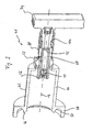
- the measuring device shown there is generally designated 40. It has an adapter 42 with an optical axis 16 sleeve-like enclosing main adapter portion 44. In the area of in FIG. 3 left axial end of the adapter 42 is designed for coupling with a laser beam providing laser system.
- the coupling means provided for this purpose comprise an axially directed annular abutment surface 46, which serves for the axial abutment and thus the axial positioning of the measuring device 40 relative to the laser system.
- the mentioned coupling means comprise a ring-like clamping section 48, which is preferably made in one piece with the adapter main section 44, for the radial clamping of a lens rim or another formation of the laser system.
- the clamping portion 48 has a plurality of circumferentially distributed threaded bores 50 for receiving radial clamping screws (not shown).
- the adapter main section 44 is detachably connected to an adjusting block 52, which forms a receiving opening 54 for a guide tube 56.
- the adjusting block 52 has threaded holes 58 for receiving fastening screws, not shown, by means of which the adapter 42 can be fastened to the adjusting block 52.
- the guide tube 56 is held axially immovably in the receiving opening 54 of the Justierblocks 52, but is adjustable by means not shown adjusting screws of the Justierblocks 52 relative to this in a radial plane.
- the adjusting block 52 in a manner not shown a the Actuallysstubus 56 radially clamped inner sleeve, which is held transversely adjustable in a housing 52 of the Justierblocks.
- Suitable Justierblöcke are commercially available.
- the Justierblock 52 allows an independent transverse adjustment of the Guide tube 56 in two mutually perpendicular radial directions. Overall, thus, the guide tube 56 can be adjusted in an achsnormalen level in any direction.
- the axial fixing of the guide tube 56 relative to the adjusting block 52 is ensured in the illustrated embodiment by an axial shoulder 60 on the outer circumference of the guide tube 56 and a screw ring 62, which is screwed onto the guide tube 56.
- the adjusting block 52 is held axially between the axial shoulder 60 and the screw ring 62.
- the guide tube 56 forms an axial guide receiving opening 66 for a lens barrel 68 which, together with the lenses of a magnifying lens arrangement, can be preassembled to form a structural unit and can be inserted into the guide tube 56 as such a pre-assembled structural unit.
- the magnifying lens arrangement corresponds in the present example case of the variant of FIG. 1 , therefore, in the meter of the FIGS. 3 to 5 the two existing lenses are also designated 10 and 12. It is understood, however, that also a different lens configuration, such as that of FIG. 2 , equally in the lens barrel 68 can be installed.
- the lens barrel 68 is axially movable in the guide receiving opening 66 of the guide tube 56, but guided non-rotatably.
- the lens barrel 68 has a machined into its outer peripheral surface, axially elongated recess 70, in which engages a non-illustrated anti-rotation screw, which is screwed into a corresponding threaded hole 72 of the guide tube 56.
- the lens barrel 68 and the guide tube 56 extend together into the sleeve-shaped main portion 44 of the adapter 42, in particular substantially equally far, and that the lens barrel 68 protrudes from the guide tube 56 in the region of its axially other end.
- a digital camera 74 in which a in the FIGS. 3 to 5 not shown image sensor is installed, such as the image sensor 14 of Figures 1 and 2 .
- An axial abutment surface 76 at the free axial end of the lens barrel 68 allows a defined axial positioning of the imaging camera 74 relative to the lens barrel 68 and thus with respect to the lenses 10, 12 installed therein.
- the coupling of the image camera 74 with the lens barrel 68 may, for example, be a threaded coupling or a radial clamping coupling be.
- the design of the measuring device 40 with an image camera 74 which can be detachably coupled to the lens barrel 68 makes it possible to resort to commercially available camera models.
- the lens barrel 68 together with the components inserted in it, can be preassembled to form a structural unit.
- These components comprise, in addition to the two lenses 10, 12, an attachment ring 78, which is inserted as a first component into the lens barrel 68 during pre-assembly and provides a planar support surface for the flat side of the lens 12.
- the attachment ring 78 abuts against an axial shoulder 80 which is formed at the transition between a larger diameter portion of the inner tube opening and a smaller diameter portion.
- a spacer tube 82 is inserted into the lens barrel 68.
- the spacer tube 82 is followed by a lens assembly 84, which in turn is preassembled as a structural unit, with the lens 10.
- the lens assembly 84 comprises an approximately pot-shaped lens frame 86, which has a central through hole for the laser beam at its bottom.
- the lens 10 is located above this hole and is supported with its flat lens side on the bottom of the pot lens frame 86.
- a centering disc 88 provides for a radial centering of the lens 10 in the lens barrel 86.
- the lens barrel 86 has on the inside of its cup shell a thread into which a lens clamping screw 90 and a threaded disc 92 behind it are screwed. In order not to injure the lens 10, the lens clamping screw 90 is not attracted to the lens 10, but locked with the threaded disc 92.
- the thus assembled lens assembly 84 is inserted into the lens barrel 68 until the lens barrel 86 abuts against the spacer tube 82.
- the lens barrel 68 is designed in the region of its adapter-side end with an internal thread into which two further threaded disks 94, 96 can be screwed, which serve to fix the remaining components in the lens barrel 68.
- the two threaded disks 94, 96 are preferably countered against each other so that axial clamping forces are not transmitted to the lens 12 via the lens holder 86 and the spacer tube 82.
- the lens barrel 68 is guided axially movably in the guide receiving opening 66 relative to the guide tube 56.
- longitudinal adjustment means are effective, which a defined longitudinal adjustment (Llindsjustage) of the lens barrel 68 opposite the guide tube 56 allow.
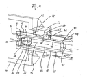
- These longitudinal adjustment means comprise an actuator 98, which is in threaded engagement with the guide tube 56 and at the same time is in axial support engagement with the lens barrel 68.
- the actuator is designed as a threaded sleeve which sits on the guide tube 56 and engages radially behind a support collar 100 formed in the region of the camera near end of the lens barrel 68.
- the threaded sleeve 98 is designed with an internal thread with which it is screwed onto a complementary external thread of the guide tube 56. Between the threaded sleeve 98 and the lens barrel 68, an annular space 102 is formed in which a trained as a helical compression spring biasing spring 104 is housed.
- the biasing spring 104 is supported axially on one end on the support collar 100 of the lens barrel 68 and axially on the other hand on the guide tube 56 and exerts a two tubes 56, 68 apart pressing biasing force.
- This axial biasing force is derived from the lens barrel 68 via its support collar 100 to a trained on the camera near end of the threaded sleeve 98, radially inwardly projecting annular web 106.
- a slide ring 108 made of a low-friction material is placed on the lens barrel 68 between the support collar 100 and the annular web 106.
- the bias spring 104 is sufficiently strong to inhibit any inadvertent play between the lens barrel 68 and the guide tube 56 during normal handling of the meter 40.
- the threaded sleeve 98 allows a defined longitudinal adjustment of the system of the lenses 10, 12 and the camera 74 relative to the guide tube 56 and thus relative to serving as a reference point stop surface 46 of the adapter 42. Because of the relatively large thread diameter (large compared for example to a Micrometer screw) is a very sensitive longitudinal adjustment of the lens barrel 68 possible. In particular, an adjustment accuracy in the axial direction of only a few micrometers can be achieved in this way.
- the maximum displacement of the lens barrel 68 in the axial direction may be, for example, in the range of a few millimeters, which is sufficient to perform M 2 measurements at conventional beam diameters, to which a longitudinal adjustability of the lens barrel 68 by three times the Rayleigh length is required.
- a gray filter 110 is installed in the lens barrel 68, which is inserted into the latter from the camera near end of the lens barrel 68 and secured therein by means of a clamping sleeve 112 with the interposition of an elastomer ring 114.
- the gray filter 110 can be exchanged in this way, so that differently dense gray filters can be used for different beam intensities.
Landscapes
- Physics & Mathematics (AREA)
- General Physics & Mathematics (AREA)
- Spectroscopy & Molecular Physics (AREA)
- Optics & Photonics (AREA)
- Lens Barrels (AREA)
- Length Measuring Devices By Optical Means (AREA)
- Photometry And Measurement Of Optical Pulse Characteristics (AREA)
- Exposure Of Semiconductors, Excluding Electron Or Ion Beam Exposure (AREA)
- Testing Of Optical Devices Or Fibers (AREA)
Priority Applications (14)
| Application Number | Priority Date | Filing Date | Title |
|---|---|---|---|
| DE502007001924T DE502007001924D1 (de) | 2007-09-13 | 2007-09-13 | Messgerät zur Vermessung eines Laserstrahls |
| ES07017968T ES2333369T3 (es) | 2007-09-13 | 2007-09-13 | Aparato de medicion para medir un rayo laser. |
| EP07017968A EP2037238B1 (de) | 2007-09-13 | 2007-09-13 | Messgerät zur Vermessung eines Laserstrahls |
| CN200880106717.7A CN101821595B (zh) | 2007-09-13 | 2008-09-12 | 用于测量被聚焦的激光束的测量装置 |
| PCT/EP2008/007575 WO2009036932A1 (de) | 2007-09-13 | 2008-09-12 | Messgerät zur vermessung eines fokussierten laserstrahls |
| CA2699629A CA2699629C (en) | 2007-09-13 | 2008-09-12 | Measuring device for measuring a focused laser beam |
| IN855KON2010 IN2010KN00855A (https=) | 2007-09-13 | 2008-09-12 | |
| US12/677,776 US8351028B2 (en) | 2007-09-13 | 2008-09-12 | Measuring device for measuring a focused laser beam |
| JP2010524407A JP5554710B2 (ja) | 2007-09-13 | 2008-09-12 | 収束されたレーザビームを測定するための測定器 |
| KR1020107008066A KR101255796B1 (ko) | 2007-09-13 | 2008-09-12 | 집속 레이저 빔 측정 장치 |
| BRPI0815425-2A BRPI0815425B1 (pt) | 2007-09-13 | 2008-09-12 | Dispositivo de medição para medir um feixe laser concentrado |
| TW097135025A TW200920334A (en) | 2007-09-13 | 2008-09-12 | Measuring device for measuring a focused laser beam |
| MX2010002894A MX2010002894A (es) | 2007-09-13 | 2008-09-12 | Dispositivo de medicion para medir un rayo laser enfocado. |
| RU2010113570/28A RU2474795C2 (ru) | 2007-09-13 | 2008-09-12 | Измерительное устройство для измерения параметров сфокусированного лазерного пучка |
Applications Claiming Priority (1)
| Application Number | Priority Date | Filing Date | Title |
|---|---|---|---|
| EP07017968A EP2037238B1 (de) | 2007-09-13 | 2007-09-13 | Messgerät zur Vermessung eines Laserstrahls |
Publications (2)
| Publication Number | Publication Date |
|---|---|
| EP2037238A1 EP2037238A1 (de) | 2009-03-18 |
| EP2037238B1 true EP2037238B1 (de) | 2009-11-04 |
Family
ID=39059375
Family Applications (1)
| Application Number | Title | Priority Date | Filing Date |
|---|---|---|---|
| EP07017968A Active EP2037238B1 (de) | 2007-09-13 | 2007-09-13 | Messgerät zur Vermessung eines Laserstrahls |
Country Status (14)
| Country | Link |
|---|---|
| US (1) | US8351028B2 (https=) |
| EP (1) | EP2037238B1 (https=) |
| JP (1) | JP5554710B2 (https=) |
| KR (1) | KR101255796B1 (https=) |
| CN (1) | CN101821595B (https=) |
| BR (1) | BRPI0815425B1 (https=) |
| CA (1) | CA2699629C (https=) |
| DE (1) | DE502007001924D1 (https=) |
| ES (1) | ES2333369T3 (https=) |
| IN (1) | IN2010KN00855A (https=) |
| MX (1) | MX2010002894A (https=) |
| RU (1) | RU2474795C2 (https=) |
| TW (1) | TW200920334A (https=) |
| WO (1) | WO2009036932A1 (https=) |
Families Citing this family (11)
| Publication number | Priority date | Publication date | Assignee | Title |
|---|---|---|---|---|
| DE102010029089B4 (de) * | 2010-05-18 | 2019-08-29 | Carl Zeiss Ag | Optisches System zur Kalibrierung einer Lichtquelle |
| CN102384782A (zh) * | 2010-09-06 | 2012-03-21 | 杭州法珀激光科技有限公司 | 手持式激光光束分析仪 |
| FR2974176B1 (fr) | 2011-04-14 | 2014-01-17 | Centre Nat Rech Scient | Analyseur spatial de faisceau laser a reglage automatique |
| CN105606213B (zh) * | 2015-12-05 | 2018-02-13 | 中国航空工业集团公司洛阳电光设备研究所 | 一种激光微脉冲峰值功率测试装置 |
| DE102016009475B4 (de) * | 2016-08-05 | 2019-06-19 | Primes GmbH Meßtechnik für die Produktion mit Laserstrahlung | Strahlleistungsmessung mit Aufweitung |
| CN110799892B (zh) * | 2017-06-23 | 2022-04-12 | 业纳光学系统有限公司 | 用于辅助调整射束扩展器的方法、调整辅助设备以及射束扩展器 |
| CN112368638A (zh) * | 2018-07-05 | 2021-02-12 | 应用材料公司 | 光掩模保护膜残胶移除 |
| US11243114B2 (en) * | 2018-09-17 | 2022-02-08 | Trumpf Lasersystems For Semiconductor Manufacturing Gmbh | Method for determining at least one beam propagation parameter of a laser beam |
| TWI729403B (zh) * | 2019-05-31 | 2021-06-01 | 致茂電子股份有限公司 | 光電元件特性測量裝置 |
| US12153208B2 (en) * | 2020-11-23 | 2024-11-26 | Coherent Lasersystems Gmbh & Co. Kg | Laser beam wavefront correction with adaptive optics and mid-field monitoring |
| CN116907369B (zh) * | 2023-09-06 | 2023-12-12 | 太原科技大学 | 一种螺旋焊管管径激光检测系统及其使用方法 |
Family Cites Families (20)
| Publication number | Priority date | Publication date | Assignee | Title |
|---|---|---|---|---|
| GB909336A (en) | 1959-11-13 | 1962-10-31 | Leitz Ernst Gmbh | Improvements in or relating to tubular guide arrangements |
| JPS6079127U (ja) | 1983-11-07 | 1985-06-01 | 長田電機工業株式会社 | レ−ザ−用パワ−メ−タ |
| JPH01168843U (https=) | 1988-05-19 | 1989-11-28 | ||
| JPH0222658A (ja) * | 1988-07-08 | 1990-01-25 | Mitsubishi Electric Corp | 電子ビーム露光方法 |
| JPH071201B2 (ja) * | 1989-01-17 | 1995-01-11 | 株式会社オプトアート | 光ビーム測定装置 |
| US5194993A (en) * | 1991-09-24 | 1993-03-16 | Eastman Kodak Company | Adjustable mount for cylindrical lens |
| FR2698182B1 (fr) * | 1992-11-13 | 1994-12-16 | Commissariat Energie Atomique | Dispositif de contrôle du centrage d'un faisceau lumineux, application à l'introduction de ce faisceau dans une fibre optique. |
| JPH071201A (ja) | 1993-02-28 | 1995-01-06 | Sanshin Kogyo Kk | 円筒部材の加工方法 |
| CN2293794Y (zh) * | 1997-04-28 | 1998-10-07 | 中国科学技术大学 | 可调式半导体激光准直头 |
| JP2000234916A (ja) | 1999-02-15 | 2000-08-29 | Konica Corp | 光ビーム形状計測装置及びアライメント測定装置 |
| JP2001004491A (ja) * | 1999-06-25 | 2001-01-12 | Sankyo Seiki Mfg Co Ltd | 光ビームの検査装置 |
| US6922232B2 (en) | 2002-09-24 | 2005-07-26 | Infineon Technologies North America Corp. | Test system for laser diode far-field pattern measurement |
| RU40103U1 (ru) * | 2004-01-08 | 2004-08-27 | Федеральное государственное унитарное предприятие "Производственное объединение "Уральский оптико-механический завод" | Устройство для определения углового рассогласования пучков лазерного излучения |
| JP3935168B2 (ja) * | 2004-08-26 | 2007-06-20 | シャープ株式会社 | レンズ鏡筒装置 |
| TW200608475A (en) | 2004-08-26 | 2006-03-01 | Adv Lcd Tech Dev Ct Co Ltd | Method of picking up sectional image of laser light |
| WO2006078349A2 (en) * | 2004-11-22 | 2006-07-27 | Meade Instruments Corporation | Scope for a firearm |
| US20060254115A1 (en) * | 2004-11-22 | 2006-11-16 | Thomas Mark A | Optical sight with side focus adjustment |
| JP4524403B2 (ja) * | 2005-05-31 | 2010-08-18 | 三菱電機株式会社 | フーリエ変換光学装置及び光制御型フェーズドアレイアンテナ装置 |
| JP4049171B2 (ja) * | 2005-07-08 | 2008-02-20 | コニカミノルタオプト株式会社 | 鏡胴ユニット並びに撮像装置 |
| US7463342B2 (en) * | 2007-05-02 | 2008-12-09 | Angstrom, Inc. | Optical tracking device using micromirror array lenses |
-
2007
- 2007-09-13 ES ES07017968T patent/ES2333369T3/es active Active
- 2007-09-13 DE DE502007001924T patent/DE502007001924D1/de active Active
- 2007-09-13 EP EP07017968A patent/EP2037238B1/de active Active
-
2008
- 2008-09-12 CA CA2699629A patent/CA2699629C/en active Active
- 2008-09-12 IN IN855KON2010 patent/IN2010KN00855A/en unknown
- 2008-09-12 MX MX2010002894A patent/MX2010002894A/es active IP Right Grant
- 2008-09-12 WO PCT/EP2008/007575 patent/WO2009036932A1/de not_active Ceased
- 2008-09-12 KR KR1020107008066A patent/KR101255796B1/ko not_active Expired - Fee Related
- 2008-09-12 RU RU2010113570/28A patent/RU2474795C2/ru not_active IP Right Cessation
- 2008-09-12 BR BRPI0815425-2A patent/BRPI0815425B1/pt not_active IP Right Cessation
- 2008-09-12 CN CN200880106717.7A patent/CN101821595B/zh active Active
- 2008-09-12 JP JP2010524407A patent/JP5554710B2/ja active Active
- 2008-09-12 US US12/677,776 patent/US8351028B2/en active Active
- 2008-09-12 TW TW097135025A patent/TW200920334A/zh unknown
Non-Patent Citations (2)
| Title |
|---|
| LINOS KATALOG, 1993 * |
| SCHÄFTER&KIRCHHOFF KATALOG: "Opto-sensorik und Messtechik", 1992 * |
Also Published As
| Publication number | Publication date |
|---|---|
| DE502007001924D1 (de) | 2009-12-17 |
| TW200920334A (en) | 2009-05-16 |
| CA2699629A1 (en) | 2009-03-26 |
| ES2333369T3 (es) | 2010-02-19 |
| BRPI0815425A2 (pt) | 2016-08-09 |
| EP2037238A1 (de) | 2009-03-18 |
| WO2009036932A1 (de) | 2009-03-26 |
| MX2010002894A (es) | 2010-04-01 |
| RU2010113570A (ru) | 2011-10-20 |
| US20100253937A1 (en) | 2010-10-07 |
| IN2010KN00855A (https=) | 2015-08-28 |
| CA2699629C (en) | 2016-04-19 |
| CN101821595A (zh) | 2010-09-01 |
| KR101255796B1 (ko) | 2013-04-17 |
| RU2474795C2 (ru) | 2013-02-10 |
| JP2010539459A (ja) | 2010-12-16 |
| KR20100063118A (ko) | 2010-06-10 |
| BRPI0815425B1 (pt) | 2019-04-09 |
| US8351028B2 (en) | 2013-01-08 |
| CN101821595B (zh) | 2014-11-26 |
| JP5554710B2 (ja) | 2014-07-23 |
Similar Documents
| Publication | Publication Date | Title |
|---|---|---|
| EP2037238B1 (de) | Messgerät zur Vermessung eines Laserstrahls | |
| DE102009007769B4 (de) | Laserbearbeitungskopf mit integrierter Sensoreinrichtung zur Fokuslagenüberwachung | |
| DE102019102330B3 (de) | Optisches System für ein Mikroskop, Mikroskop mit einem optischen System und Verfahren zur Abbildung eines Objekts unter Verwendung eines Mikroskops | |
| DE102017217320A1 (de) | Linsensystem variabler brennweite und fokuskontrolle und -steuerung | |
| EP3583390A2 (de) | Verfahren und vorrichtung zur erfassung einer fokuslage eines laserstrahls | |
| EP1797813A1 (de) | Optische Messvorrichtung zum Vermessen eines Hohlraums | |
| DE102009037841A1 (de) | Wellenfrontanalysesystem und optisches System mit Mikroskop und Wellenfrontanalysesystem | |
| DE102013113265B4 (de) | Vorrichtung zur berührungslosen optischen Abstandsmessung | |
| EP3313607B1 (de) | Laserbearbeitungskopf und laserbearbeitungsmaschine damit | |
| DE102016212507A1 (de) | Chromatisch-konfokaler Bereichssensor mit Kamerateil | |
| WO2014023344A1 (de) | Verbesserter chromatischer sensor und verfahren | |
| EP2808716B1 (de) | Fotografisches Weitwinkelobjektiv mit Innenfokussierung | |
| DE102014201779A1 (de) | Strahlpropagationskamera und Verfahren zur Lichtstrahlanalyse | |
| DE102012223712A1 (de) | Variables abbildungssystem mit objektiv fester brennweite | |
| EP2847541B1 (de) | KOORDINATENMESSGERÄT MIT WEIßLICHTSENSOR | |
| EP1355181B1 (de) | Laser-scanning-Mikroskop mit Kollimator- und/oder Pinholeoptik | |
| DE102015014387B3 (de) | Vorrichtung und Verfahren zur Strahlanalyse mit einem variablen optischen Element | |
| DE202017006898U1 (de) | Mikroskop mit Kollisionsschutz | |
| DE102022114157B4 (de) | Vorrichtung und Verfahren zur Fokuslagen-Bestimmung mit Berücksichtigung von Prozessgas | |
| WO2023208863A1 (de) | Vorrichtung und verfahren zur fokuslagen-bestimmung mit berücksichtigung von prozessgas | |
| EP2767797B1 (de) | Niedrigkohärenzinterferometer und Verfahren zur ortsaufgelösten optischen Vermessung des Oberflächenprofils eines Objekts | |
| DE3832088C2 (https=) | ||
| EP2883018B1 (de) | Koordinatenmessgerät zur bestimmung von raumkoordinaten an einem messobjekt | |
| DE102018113136A1 (de) | Kameramodul und Kamerasystem mit einem Kameramodul | |
| EP3353592A1 (de) | Optische stahlformungseinheit, entfernungsmessvorrichtung und laserbeleuchter |
Legal Events
| Date | Code | Title | Description |
|---|---|---|---|
| PUAI | Public reference made under article 153(3) epc to a published international application that has entered the european phase |
Free format text: ORIGINAL CODE: 0009012 |
|
| 17P | Request for examination filed |
Effective date: 20080910 |
|
| AK | Designated contracting states |
Kind code of ref document: A1 Designated state(s): AT BE BG CH CY CZ DE DK EE ES FI FR GB GR HU IE IS IT LI LT LU LV MC MT NL PL PT RO SE SI SK TR |
|
| AX | Request for extension of the european patent |
Extension state: AL BA HR MK RS |
|
| GRAP | Despatch of communication of intention to grant a patent |
Free format text: ORIGINAL CODE: EPIDOSNIGR1 |
|
| GRAS | Grant fee paid |
Free format text: ORIGINAL CODE: EPIDOSNIGR3 |
|
| GRAA | (expected) grant |
Free format text: ORIGINAL CODE: 0009210 |
|
| AK | Designated contracting states |
Kind code of ref document: B1 Designated state(s): DE ES FR GB IT |
|
| REG | Reference to a national code |
Ref country code: GB Ref legal event code: FG4D Free format text: NOT ENGLISH |
|
| AKX | Designation fees paid |
Designated state(s): DE ES FR GB IT |
|
| REF | Corresponds to: |
Ref document number: 502007001924 Country of ref document: DE Date of ref document: 20091217 Kind code of ref document: P |
|
| REG | Reference to a national code |
Ref country code: ES Ref legal event code: FG2A Ref document number: 2333369 Country of ref document: ES Kind code of ref document: T3 |
|
| PLBE | No opposition filed within time limit |
Free format text: ORIGINAL CODE: 0009261 |
|
| STAA | Information on the status of an ep patent application or granted ep patent |
Free format text: STATUS: NO OPPOSITION FILED WITHIN TIME LIMIT |
|
| 26N | No opposition filed |
Effective date: 20100805 |
|
| REG | Reference to a national code |
Ref country code: FR Ref legal event code: PLFP Year of fee payment: 10 |
|
| REG | Reference to a national code |
Ref country code: FR Ref legal event code: PLFP Year of fee payment: 11 |
|
| REG | Reference to a national code |
Ref country code: FR Ref legal event code: PLFP Year of fee payment: 12 |
|
| REG | Reference to a national code |
Ref country code: GB Ref legal event code: 732E Free format text: REGISTERED BETWEEN 20200116 AND 20200122 Ref country code: DE Ref legal event code: R082 Ref document number: 502007001924 Country of ref document: DE Representative=s name: WUESTHOFF & WUESTHOFF, PATENTANWAELTE PARTG MB, DE Ref country code: DE Ref legal event code: R081 Ref document number: 502007001924 Country of ref document: DE Owner name: ALCON INC., CH Free format text: FORMER OWNER: WAVELIGHT AG, 91058 ERLANGEN, DE |
|
| REG | Reference to a national code |
Ref country code: ES Ref legal event code: PC2A Owner name: ALCON INC. Effective date: 20200402 |
|
| P01 | Opt-out of the competence of the unified patent court (upc) registered |
Free format text: CASE NUMBER: UPC_APP_121269/2023 Effective date: 20230510 |
|
| PGFP | Annual fee paid to national office [announced via postgrant information from national office to epo] |
Ref country code: DE Payment date: 20250819 Year of fee payment: 19 |
|
| PGFP | Annual fee paid to national office [announced via postgrant information from national office to epo] |
Ref country code: IT Payment date: 20250827 Year of fee payment: 19 |
|
| PGFP | Annual fee paid to national office [announced via postgrant information from national office to epo] |
Ref country code: GB Payment date: 20250821 Year of fee payment: 19 |
|
| PGFP | Annual fee paid to national office [announced via postgrant information from national office to epo] |
Ref country code: FR Payment date: 20250821 Year of fee payment: 19 |
|
| PGFP | Annual fee paid to national office [announced via postgrant information from national office to epo] |
Ref country code: ES Payment date: 20251014 Year of fee payment: 19 |