EP2037238B1 - Measuring device for measuring a laser beam - Google Patents
Measuring device for measuring a laser beam Download PDFInfo
- Publication number
- EP2037238B1 EP2037238B1 EP07017968A EP07017968A EP2037238B1 EP 2037238 B1 EP2037238 B1 EP 2037238B1 EP 07017968 A EP07017968 A EP 07017968A EP 07017968 A EP07017968 A EP 07017968A EP 2037238 B1 EP2037238 B1 EP 2037238B1
- Authority
- EP
- European Patent Office
- Prior art keywords
- lens
- lenses
- magnification
- laser beam
- lens system
- Prior art date
- Legal status (The legal status is an assumption and is not a legal conclusion. Google has not performed a legal analysis and makes no representation as to the accuracy of the status listed.)
- Active
Links
- 230000008878 coupling Effects 0.000 claims description 11
- 238000010168 coupling process Methods 0.000 claims description 11
- 238000005859 coupling reaction Methods 0.000 claims description 11
- 230000001419 dependent effect Effects 0.000 claims 1
- 230000003287 optical effect Effects 0.000 description 12
- 238000013461 design Methods 0.000 description 4
- 125000006850 spacer group Chemical group 0.000 description 4
- 238000006073 displacement reaction Methods 0.000 description 3
- 238000005259 measurement Methods 0.000 description 3
- 230000005540 biological transmission Effects 0.000 description 2
- 238000010276 construction Methods 0.000 description 2
- 230000000694 effects Effects 0.000 description 2
- 238000011156 evaluation Methods 0.000 description 2
- 230000004308 accommodation Effects 0.000 description 1
- 230000004075 alteration Effects 0.000 description 1
- 230000015572 biosynthetic process Effects 0.000 description 1
- 239000000969 carrier Substances 0.000 description 1
- 230000000295 complement effect Effects 0.000 description 1
- 230000006835 compression Effects 0.000 description 1
- 238000007906 compression Methods 0.000 description 1
- 210000004087 cornea Anatomy 0.000 description 1
- 230000004069 differentiation Effects 0.000 description 1
- 229920001971 elastomer Polymers 0.000 description 1
- 239000000806 elastomer Substances 0.000 description 1
- 238000005516 engineering process Methods 0.000 description 1
- 239000002783 friction material Substances 0.000 description 1
- 238000003384 imaging method Methods 0.000 description 1
- 238000002430 laser surgery Methods 0.000 description 1
- 230000004807 localization Effects 0.000 description 1
- 238000000691 measurement method Methods 0.000 description 1
- 238000000034 method Methods 0.000 description 1
- 238000012986 modification Methods 0.000 description 1
- 230000004048 modification Effects 0.000 description 1
- 230000007935 neutral effect Effects 0.000 description 1
- 230000002093 peripheral effect Effects 0.000 description 1
- 230000005855 radiation Effects 0.000 description 1
- 230000009467 reduction Effects 0.000 description 1
- 239000004065 semiconductor Substances 0.000 description 1
- 238000001356 surgical procedure Methods 0.000 description 1
- 230000007704 transition Effects 0.000 description 1
Images


Classifications
-
- G—PHYSICS
- G01—MEASURING; TESTING
- G01J—MEASUREMENT OF INTENSITY, VELOCITY, SPECTRAL CONTENT, POLARISATION, PHASE OR PULSE CHARACTERISTICS OF INFRARED, VISIBLE OR ULTRAVIOLET LIGHT; COLORIMETRY; RADIATION PYROMETRY
- G01J1/00—Photometry, e.g. photographic exposure meter
- G01J1/42—Photometry, e.g. photographic exposure meter using electric radiation detectors
- G01J1/4257—Photometry, e.g. photographic exposure meter using electric radiation detectors applied to monitoring the characteristics of a beam, e.g. laser beam, headlamp beam
-
- G—PHYSICS
- G01—MEASURING; TESTING
- G01J—MEASUREMENT OF INTENSITY, VELOCITY, SPECTRAL CONTENT, POLARISATION, PHASE OR PULSE CHARACTERISTICS OF INFRARED, VISIBLE OR ULTRAVIOLET LIGHT; COLORIMETRY; RADIATION PYROMETRY
- G01J1/00—Photometry, e.g. photographic exposure meter
- G01J1/02—Details
- G01J1/04—Optical or mechanical part supplementary adjustable parts
- G01J1/0407—Optical elements not provided otherwise, e.g. manifolds, windows, holograms, gratings
- G01J1/0411—Optical elements not provided otherwise, e.g. manifolds, windows, holograms, gratings using focussing or collimating elements, i.e. lenses or mirrors; Aberration correction
-
- G—PHYSICS
- G01—MEASURING; TESTING
- G01J—MEASUREMENT OF INTENSITY, VELOCITY, SPECTRAL CONTENT, POLARISATION, PHASE OR PULSE CHARACTERISTICS OF INFRARED, VISIBLE OR ULTRAVIOLET LIGHT; COLORIMETRY; RADIATION PYROMETRY
- G01J1/00—Photometry, e.g. photographic exposure meter
- G01J1/02—Details
- G01J1/04—Optical or mechanical part supplementary adjustable parts
- G01J1/0407—Optical elements not provided otherwise, e.g. manifolds, windows, holograms, gratings
- G01J1/0448—Adjustable, e.g. focussing
Definitions
- the invention relates to a measuring device for measuring a laser beam.
- the laser beam to be measured serves in particular for use in ophthalmic laser surgery, for example as part of a photorefractive treatment of the cornea or the lens. This is only an example, of course; In principle, the invention is not subject to any restrictions with regard to the intended use of the laser beam to be measured. Precise knowledge of certain beam parameters is generally required in many laser applications, with photonography in semiconductor technology as well as laser scanning or laser description of optical data carriers being mentioned as only two of many other examples besides laser eye surgery.
- interesting beam parameters of a laser beam are often the beam diameter, in particular in the region of the beam waist, as well as the beam divergence, but also other parameters such as the diffraction index (usually abbreviated by M 2 ) or the intensity profile transverse to the beam direction.
- Knife Edge or slit methods are known in which a blade or a sufficiently narrow gap is moved across the beam and depending on the blade or gap position, the transmitted power is measured by means of a detector. By differentiation of the transmission curve thus obtained, the intensity profile can then be determined, by means of which the beam diameter can again be determined.
- US 2004/066504 A1 discloses a measuring arrangement for measuring the beam pattern of the laser radiation emitted by a laser diode.
- the laser diode is arranged on a support table, which is adjustable in three mutually perpendicular linear spatial directions.
- the measuring arrangement comprises two cameras, one of which serves to receive an image of the focused laser beam of the laser diode and the other of which serves to receive an image of the far field pattern of the laser beam.
- the first camera is located in the image-side focal point of an afocal telescope pair formed by an objective lens and a relay lens.
- the laser diode is positioned by controlling the table carrying it so that the point of light leakage from the laser diode is at the object focal point of the lens pair.
- US 2006/043258 A1 shows a Knife Edge measuring arrangement for measuring the light of a laser beam source.
- the measuring arrangement has a CCD image sensor as well as a magnification optical unit between the blade and the image sensor with a single objective lens.
- the image sensor and the magnification optics are arranged on an adjustment table, which is adjustable in all three linear spatial directions.
- the accommodation of lenses in a cylindrical receiving part is the example of a lens of a camera in CH 400 758 A described.
- the invention provides the use of a measuring device having the features of claim 1.
- the meter includes a magnifying lens assembly having at least two in the strades A laser beam arranged in succession lenses, wherein pairwise successive lenses of the magnification lens assembly each have coincident focal points, behind the magnifying lens assembly in its focus arranged electronic image sensor for receiving an image of the magnified laser beam and Leksverstellstoff which a common adjustment of the lenses of the magnification lens assembly and the image sensor along the beam path allow relative to a reference point of the meter.
- magnification factor of a single magnifying lens results in a dependence of the magnification factor of a single magnifying lens on the beam diameter of the laser beam to be measured. If, as a magnification factor, the quotient of the diameter of the enlarged beam and the diameter of the diameter of the unextended beam are considered, it follows in particular that the magnification factor of a single magnifying lens can be markedly larger for smaller waist diameters than for larger waist diameters. The assumption of a nominal, constant magnification scale can thus lead to significant measurement errors when using a single magnifying lens when foci of different waist diameters are measured.
- the inventors have recognized that with a multi-lens system, the dependency of the magnification scale on the beam diameter can be eliminated, namely when each pair of successive lenses has respective coincident focal points. In this case, it can be assumed that the magnification scale is always constant, no matter how large the waist diameter of the beam to be measured is. This allows a much more accurate determination of the actual waist diameter of the laser beam to be measured.
- the longitudinal adjustment means of the measuring device allow a defined adjustment of the entirety of the lenses and of the image sensor along the beam path relative to a measuring device's own reference point.
- Measuring device is called, the reference point is located on or in the meter and thus is stationary relative to the meter as a whole.
- the adjustability of the system of lenses and image sensor along the beam path allows a precise localization of the beam waist of the laser beam to be measured and consequent precise adjustment of the meter, so that the focus of the laser beam coincides with the focal point of the first lens of the magnification lens assembly.
- the longitudinal adjustability of the lenses and the image sensor is alternatively or additionally useful to determine the beam diameter at different locations along the laser beam, in other words to determine a diameter profile of the laser beam.
- a diameter profile allows statements, for example, about the divergence of the beam and about the diffraction factor. It is understood that for the determination of these and other beam parameters, a suitably programmed electronic evaluation unit is provided, which evaluates and interprets the electrical image signals supplied by the image sensor and possibly buffered in a memory.
- the range of adjustability for the system of lenses and image sensor provided by the longitudinal adjustment means preferably extends over at least three times the Rayleigh length of the laser beam.
- the longitudinal adjustment means may additionally permit longitudinal adjustment of the lenses relative to each other and / or relative to the image sensor, for example for calibration purposes or in order to be able to compensate for component and assembly tolerances.
- the magnifying lens arrangement has a total of two lenses.
- the magnification power can be divided into two magnification levels - each consisting of a pair of lenses - are divided, which is why with the same overall magnification each pair of lenses can have a lower magnification than the only pair of lenses in the embodiment with a total of two lenses.
- All lenses of the magnification lens arrangement can each be designed as a converging lens.
- the magnification lens arrangement has at least one diverging lens, but at least the last lens is designed as a converging lens. Because of its negative focal length, the use of a diverging lens allows space reduction compared to a convergent lens. This can be used especially in embodiments with more than two lenses, if the focal length of the first lens can be chosen larger and therefore the space gain when using a diverging lens more significant than in solutions with a total of two lenses, where the first lens only a comparatively short focal length possesses.
- the last lens is to be designed as a converging lens because the image sensor requires a real image of the laser beam.
- the magnification lens assembly alone contains plano-convex or plano-concave lenses, but not bilaterally curved lenses, although of course this is not a must.
- the measuring device preferably comprises transverse displacement means, which allow an adjustment of at least the first lens of the magnification lens arrangement transversely, in particular perpendicular to the beam path relative to the above-mentioned reference point of the measuring device. It has been found that misalignment of the first lens of the magnifying lens assembly across the beam path can have a particularly strong effect on the position of the image position on the image sensor, the wavefront deformations and the image distortions, at any rate more than corresponding misalignments of the other lenses.
- the first lens should be transversely adjustable. According to a variant, it can be transversely adjustable on its own, ie independently of the other lenses and independently of the image sensor. According to another variant, the first lens can be used together with at least one further lens of the magnification lens arrangement, in particular together with all the lenses of the magnification lens arrangement, and preferably also be transversely adjustable together with the image sensor as a unit.
- the transverse displacement means expediently permit independent adjustment of at least the first lens of the magnification lens arrangement in two mutually perpendicular transverse directions.
- the construction of the measuring device is such that at least a part of the lenses, in particular all the lenses of the magnification lens arrangement in the beam path are successively installed in a lens barrel, which is adjustable by means of the longitudinal adjustment in the direction of its tube axis relative to the reference point.
- the lens barrel is axially displaceable, but guided against rotation in a guide receiving opening of a particular tube-shaped designed guide body, wherein the Leksverstellstoff between the lens barrel and the guide body are effective.
- the lens barrel can protrude axially out of the guide body at one end and be formed in the region of its protruding end for mechanical coupling with a camera containing the image sensor.
- the guide body carries an adapter enclosing the beam path for coupling the measuring device to a laser system providing the laser beam.
- the adapter is preferably a separate from the guide body component which is interchangeable connected to the guide body. This allows a modular design of the measuring device, for which then a plurality of optionally usable, different adapters can be provided for coupling to different laser systems.
- the discussed Querverstellstoff can be effective between the adapter and the guide body.
- the adapter expediently forms an abutment surface, which is axially directed with respect to a beam axis of the laser beam, for the laser system.
- This stop surface can then serve as a reference point for the longitudinal and optionally transverse adjustment of the optical components of the measuring device.
- the magnification lens assembly comprises a total of two optically thin lenses 10, 12, both of which are each formed as a plano-convex converging lens.
- the laser beam to be measured first strikes the lens 10 and then the lens 12 before its magnified image is captured by an electronic image sensor 14.
- the image sensor may be, for example, a CCD or a CMOS image sensor.
- the optical axis of the magnification lens arrangement is indicated at 16. To avoid optical aberrations, it is desirable if the beam axis of the laser beam coincides with the optical axis 16.
- suitable Querverstellstoff provided by means of which the lenses of the magnification lens assembly and optionally also the image sensor are adjustable transversely to the beam direction so that the optical axis 16 coincides substantially exactly with the beam axis.
- the lens 10 in FIG. 1 has a focal length f 1 ; their two focal points (object side and image side) are designated 18 and 20 respectively.
- the lens 12 has a focal length f 2 . It is arranged so that its object-side focal point coincides with the image-side focal point 20 of the first lens 10. On the image side, the lens 12 has a focal point 22. With this focal point 22, the sensor plane of the image sensor 14 coincides.
- the beam waist of the laser beam to be measured is at the focal point 18, it is imaged on the image sensor 14 with a magnification scale independent of the waist diameter.
- the image sensor 14 is connected to electronic evaluation means not shown in detail, which receive the image signals of the sensor 14, possibly convert it into digital form and determine therefrom the enlarged and the actual (non-enlarged) waist diameter.
- one or more neutral value filters can be arranged in its beam path.
- the optical thickness of the gray filter then leads to a slight offset of the focal point 22, which is to be considered in the positioning of the image sensor 14.
- the curved sides of the lenses 10, 12 each face the beam portion of lower divergence.
- the enlargement of the waist diameter caused by the first lens 10 is accompanied by a parallelization of the beam, for which reason the laser beam has less divergence on the image side of the lens 10 than on the object side.
- the laser beam has stronger divergence on its image side.
- FIG. 1 shown arrangement of the lenses with facing curved sides.
- the measure, the plan lens pages turn the beam sections of greater divergence and turn the curved lens sides the beam sections weaker divergence, it allows to keep the caused by the lenses 10, 12 wavefront deformations low and thus reduce the image distortion to a minimum.
- the magnification scale should be about 20 (ie, the waist diameter on the image sensor 14 should be twenty times larger than the unimpeded waist diameter), for the lens 10, for example, a focal length of about 3mm and for the lens 12 a focal length of about 60mm are chosen. Overall, a comparatively short design of the measuring device can be achieved with these focal lengths.
- the above figures are purely exemplary; In particular, other magnification-scale values may be sought which accordingly may require other focal lengths of the lenses 10,12.
- the magnification lens arrangement comprises a total of four - again optically thin - lenses, which are now designated 24, 26, 28, 30.
- the image sensor is further denoted by 14 and the optical axis is further denoted by 16.
- the second lens 26 and the fourth lens 28 seen in the propagation direction of the beam are each designed as a plano-convex condenser lens, while the first lens 24 and the third lens 28 are each referred to as Plan-concave diverging lens are executed.
- the lens pair 24, 26 forms, as it were, a first magnification stage of the magnification lens arrangement, while the second lens pair 28, 30 forms a second magnification stage.
- the magnification factor of both magnification levels may be the same or different; the overall magnification scale results from the product of the magnification factors of the two magnification levels.
- the two converging lenses 26, 30 in the example shown have the same focal length; Because of their negative focal length, the diverging lenses 24, 28 are respectively behind the focal point of the subsequent condenser lens, but again so that they coincide with their (virtual) focal point 26 ) Focus coincide with the focal point of each subsequent converging lens. That is, the focal point 32 is at the same time a (virtual) focal point of the lens 24, and the focal points 34, 36 also each correspond to a (virtual) focal point of the diverging lens 28.
- magnification of the magnifying lens assembly should the magnification of the magnifying lens assembly turn about 20, so the converging lenses 26, 30, for example, each have a focal length of about 42 mm, while for the diverging lenses a focal length of about -9 mm can be selected.
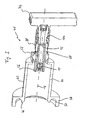
- the measuring device shown there is generally designated 40. It has an adapter 42 with an optical axis 16 sleeve-like enclosing main adapter portion 44. In the area of in FIG. 3 left axial end of the adapter 42 is designed for coupling with a laser beam providing laser system.
- the coupling means provided for this purpose comprise an axially directed annular abutment surface 46, which serves for the axial abutment and thus the axial positioning of the measuring device 40 relative to the laser system.
- the mentioned coupling means comprise a ring-like clamping section 48, which is preferably made in one piece with the adapter main section 44, for the radial clamping of a lens rim or another formation of the laser system.
- the clamping portion 48 has a plurality of circumferentially distributed threaded bores 50 for receiving radial clamping screws (not shown).
- the adapter main section 44 is detachably connected to an adjusting block 52, which forms a receiving opening 54 for a guide tube 56.
- the adjusting block 52 has threaded holes 58 for receiving fastening screws, not shown, by means of which the adapter 42 can be fastened to the adjusting block 52.
- the guide tube 56 is held axially immovably in the receiving opening 54 of the Justierblocks 52, but is adjustable by means not shown adjusting screws of the Justierblocks 52 relative to this in a radial plane.
- the adjusting block 52 in a manner not shown a the Actuallysstubus 56 radially clamped inner sleeve, which is held transversely adjustable in a housing 52 of the Justierblocks.
- Suitable Justierblöcke are commercially available.
- the Justierblock 52 allows an independent transverse adjustment of the Guide tube 56 in two mutually perpendicular radial directions. Overall, thus, the guide tube 56 can be adjusted in an achsnormalen level in any direction.
- the axial fixing of the guide tube 56 relative to the adjusting block 52 is ensured in the illustrated embodiment by an axial shoulder 60 on the outer circumference of the guide tube 56 and a screw ring 62, which is screwed onto the guide tube 56.
- the adjusting block 52 is held axially between the axial shoulder 60 and the screw ring 62.
- the guide tube 56 forms an axial guide receiving opening 66 for a lens barrel 68 which, together with the lenses of a magnifying lens arrangement, can be preassembled to form a structural unit and can be inserted into the guide tube 56 as such a pre-assembled structural unit.
- the magnifying lens arrangement corresponds in the present example case of the variant of FIG. 1 , therefore, in the meter of the FIGS. 3 to 5 the two existing lenses are also designated 10 and 12. It is understood, however, that also a different lens configuration, such as that of FIG. 2 , equally in the lens barrel 68 can be installed.
- the lens barrel 68 is axially movable in the guide receiving opening 66 of the guide tube 56, but guided non-rotatably.
- the lens barrel 68 has a machined into its outer peripheral surface, axially elongated recess 70, in which engages a non-illustrated anti-rotation screw, which is screwed into a corresponding threaded hole 72 of the guide tube 56.
- the lens barrel 68 and the guide tube 56 extend together into the sleeve-shaped main portion 44 of the adapter 42, in particular substantially equally far, and that the lens barrel 68 protrudes from the guide tube 56 in the region of its axially other end.
- a digital camera 74 in which a in the FIGS. 3 to 5 not shown image sensor is installed, such as the image sensor 14 of Figures 1 and 2 .
- An axial abutment surface 76 at the free axial end of the lens barrel 68 allows a defined axial positioning of the imaging camera 74 relative to the lens barrel 68 and thus with respect to the lenses 10, 12 installed therein.
- the coupling of the image camera 74 with the lens barrel 68 may, for example, be a threaded coupling or a radial clamping coupling be.
- the design of the measuring device 40 with an image camera 74 which can be detachably coupled to the lens barrel 68 makes it possible to resort to commercially available camera models.
- the lens barrel 68 together with the components inserted in it, can be preassembled to form a structural unit.
- These components comprise, in addition to the two lenses 10, 12, an attachment ring 78, which is inserted as a first component into the lens barrel 68 during pre-assembly and provides a planar support surface for the flat side of the lens 12.
- the attachment ring 78 abuts against an axial shoulder 80 which is formed at the transition between a larger diameter portion of the inner tube opening and a smaller diameter portion.
- a spacer tube 82 is inserted into the lens barrel 68.
- the spacer tube 82 is followed by a lens assembly 84, which in turn is preassembled as a structural unit, with the lens 10.
- the lens assembly 84 comprises an approximately pot-shaped lens frame 86, which has a central through hole for the laser beam at its bottom.
- the lens 10 is located above this hole and is supported with its flat lens side on the bottom of the pot lens frame 86.
- a centering disc 88 provides for a radial centering of the lens 10 in the lens barrel 86.
- the lens barrel 86 has on the inside of its cup shell a thread into which a lens clamping screw 90 and a threaded disc 92 behind it are screwed. In order not to injure the lens 10, the lens clamping screw 90 is not attracted to the lens 10, but locked with the threaded disc 92.
- the thus assembled lens assembly 84 is inserted into the lens barrel 68 until the lens barrel 86 abuts against the spacer tube 82.
- the lens barrel 68 is designed in the region of its adapter-side end with an internal thread into which two further threaded disks 94, 96 can be screwed, which serve to fix the remaining components in the lens barrel 68.
- the two threaded disks 94, 96 are preferably countered against each other so that axial clamping forces are not transmitted to the lens 12 via the lens holder 86 and the spacer tube 82.
- the lens barrel 68 is guided axially movably in the guide receiving opening 66 relative to the guide tube 56.
- longitudinal adjustment means are effective, which a defined longitudinal adjustment (Llindsjustage) of the lens barrel 68 opposite the guide tube 56 allow.
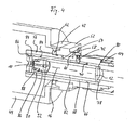
- These longitudinal adjustment means comprise an actuator 98, which is in threaded engagement with the guide tube 56 and at the same time is in axial support engagement with the lens barrel 68.
- the actuator is designed as a threaded sleeve which sits on the guide tube 56 and engages radially behind a support collar 100 formed in the region of the camera near end of the lens barrel 68.
- the threaded sleeve 98 is designed with an internal thread with which it is screwed onto a complementary external thread of the guide tube 56. Between the threaded sleeve 98 and the lens barrel 68, an annular space 102 is formed in which a trained as a helical compression spring biasing spring 104 is housed.
- the biasing spring 104 is supported axially on one end on the support collar 100 of the lens barrel 68 and axially on the other hand on the guide tube 56 and exerts a two tubes 56, 68 apart pressing biasing force.
- This axial biasing force is derived from the lens barrel 68 via its support collar 100 to a trained on the camera near end of the threaded sleeve 98, radially inwardly projecting annular web 106.
- a slide ring 108 made of a low-friction material is placed on the lens barrel 68 between the support collar 100 and the annular web 106.
- the bias spring 104 is sufficiently strong to inhibit any inadvertent play between the lens barrel 68 and the guide tube 56 during normal handling of the meter 40.
- the threaded sleeve 98 allows a defined longitudinal adjustment of the system of the lenses 10, 12 and the camera 74 relative to the guide tube 56 and thus relative to serving as a reference point stop surface 46 of the adapter 42. Because of the relatively large thread diameter (large compared for example to a Micrometer screw) is a very sensitive longitudinal adjustment of the lens barrel 68 possible. In particular, an adjustment accuracy in the axial direction of only a few micrometers can be achieved in this way.
- the maximum displacement of the lens barrel 68 in the axial direction may be, for example, in the range of a few millimeters, which is sufficient to perform M 2 measurements at conventional beam diameters, to which a longitudinal adjustability of the lens barrel 68 by three times the Rayleigh length is required.
- a gray filter 110 is installed in the lens barrel 68, which is inserted into the latter from the camera near end of the lens barrel 68 and secured therein by means of a clamping sleeve 112 with the interposition of an elastomer ring 114.
- the gray filter 110 can be exchanged in this way, so that differently dense gray filters can be used for different beam intensities.
Landscapes
- Physics & Mathematics (AREA)
- General Physics & Mathematics (AREA)
- Spectroscopy & Molecular Physics (AREA)
- Optics & Photonics (AREA)
- Lens Barrels (AREA)
- Length Measuring Devices By Optical Means (AREA)
- Photometry And Measurement Of Optical Pulse Characteristics (AREA)
- Exposure Of Semiconductors, Excluding Electron Or Ion Beam Exposure (AREA)
- Testing Of Optical Devices Or Fibers (AREA)
Description
Die Erfindung betrifft ein Messgerät zur Vermessung eines Laserstrahls. Der zu vermessende Laserstrahl dient insbesondere zum Einsatz in der ophtalmologischen Laserchirurgie, etwa im Rahmen einer photorefraktiven Behandlung der Kornea oder der Linse. Dies ist freilich nur ein Beispiel; grundsätzlich ist die Erfindung keinerlei Einschränkungen hinsichtlich des Einsatzzwecks des zu vermessenden Laserstrahls unterworfen. Präzises Wissen über bestimmte Strahlparameter ist generell bei vielen Laseranwendungen erforderlich, wobei nur als zwei von zahlreichen anderen Beispielen neben der Laserchirurgie des Auges die Photolithographie in der Halbleitertechnik sowie die Laserabtastung oder Laserbeschreibung von optischen Datenträgern genannt werden können.The invention relates to a measuring device for measuring a laser beam. The laser beam to be measured serves in particular for use in ophthalmic laser surgery, for example as part of a photorefractive treatment of the cornea or the lens. This is only an example, of course; In principle, the invention is not subject to any restrictions with regard to the intended use of the laser beam to be measured. Precise knowledge of certain beam parameters is generally required in many laser applications, with photonography in semiconductor technology as well as laser scanning or laser description of optical data carriers being mentioned as only two of many other examples besides laser eye surgery.
Interessierende Strahlparameter eines Laserstrahl sind häufig der Strahldurchmesser, insbesondere im Bereich der Strahltaille, sowie die Strahldivergenz, aber auch andere Parameter wie die Beugungsmaßzahl (üblicherweise abgekürzt durch M2) oder das Intensitätsprofil quer zur Strahlrichtung.Interesting beam parameters of a laser beam are often the beam diameter, in particular in the region of the beam waist, as well as the beam divergence, but also other parameters such as the diffraction index (usually abbreviated by M 2 ) or the intensity profile transverse to the beam direction.
Zur Vermessung eines Laserstrahls sind sogenannte Knife-Edge- oder Spaltmethoden bekannt, bei denen eine Klinge oder ein hinreichend schmaler Spalt quer durch den Strahl hindurchbewegt wird und abhängig von der Klingen- bzw. Spaltposition die transmittierte Leistung mittels eines Detektors gemessen wird. Durch Differentiation der so gewonnenen Transmissionskurve kann anschließend das Intensitätsprofil ermittelt werden, anhand dessen wiederum der Strahldurchmesser bestimmt werden kann.To measure a laser beam so-called Knife Edge or slit methods are known in which a blade or a sufficiently narrow gap is moved across the beam and depending on the blade or gap position, the transmitted power is measured by means of a detector. By differentiation of the transmission curve thus obtained, the intensity profile can then be determined, by means of which the beam diameter can again be determined.
Als Alternative zu den obigen jeweils auf einer "Abtastung" des Strahls beruhenden Transmissionsmessmethoden ist es beispielsweise aus
Die Unterbringung von Linsen in einem zylindrischen Aufnahmeteil ist am Beispiel eines Objektivs einer Fotokamera in
Die Erfindung stellt demgegenüber die Verwendung eines Messgeräts mit den Merkmalen des Anspruchs 1 bereit. Das Messgerät umfasst eine Vergrößerungslinsenanordnung mit mindestens zwei im Strades Laserstrahls hintereinander angeordneten Linsen, wobei paarweise aufeinanderfolgende Linsen der Vergrößerungslinsenanordnung jeweils zusammenfallende Brennpunkte haben, einen hinter der Vergrößerungslinsenanordnung in deren Brennpunkt angeordneten elektronischen Bildsensor zur Aufnahme eines Bilds des vergrößerten Laserstrahls sowie Längsverstellmittel, welche eine gemeinsame Verstellung der Linsen der Vergrößerungslinsenanordnung und des Bildsensors entlang des Strahlengangs relativ zu einem Referenzpunkt des Messgeräts gestatten.In contrast, the invention provides the use of a measuring device having the features of
Aus der Fachliteratur zur Optik Gaußscher Strahlen (vgl. z.B.
Die Erfinder haben erkannt, dass mit einem Mehrlinsensystem die Abhängigkeit des Vergrößerungsmaßstabs vom Strahldurchmesser beseitigt werden kann, nämlich dann, wenn jedes Paar aufeinanderfolgender Linsen jeweils zusammenfallende Brennpunkte hat. In diesem Fall kann von einem stets konstanten Vergrößerungsmaßstab ausgegangen werden, gleichgültig wie groß der Taillendurchmesser des zu vermessenden Strahls ist. Dies erlaubt eine erheblich präzisere Bestimmung des tatsächlichen Taillendurchmessers des zu vermessenden Laserstrahls.The inventors have recognized that with a multi-lens system, the dependency of the magnification scale on the beam diameter can be eliminated, namely when each pair of successive lenses has respective coincident focal points. In this case, it can be assumed that the magnification scale is always constant, no matter how large the waist diameter of the beam to be measured is. This allows a much more accurate determination of the actual waist diameter of the laser beam to be measured.
Die Längsverstellmittel des erfindungsgemäßen Messgeräts gestatten eine definierte Verstellung der Gesamtheit der Linsen und des Bildsensors entlang des Strahlengangs relativ zu einem messgeräteeigenen Referenzpunkt. Messgeräteeigen heißt, der Referenzpunkt befindet sich an oder in dem Messgerät und ist somit relativ zu dem Messgerät als Ganzem stationär. Die Verstellbarkeit des Systems aus Linsen und Bildsensor längs des Strahlengangs ermöglicht eine präzise Lokalisierung der Strahltaille des zu vermessenden Laserstrahls und daraus folgend eine präzise Einstellung des Messgeräts, so dass der Fokus des Laserstrahls mit dem Brennpunkt der ersten Linse der Vergrößerungslinsenanordnung zusammenfällt.The longitudinal adjustment means of the measuring device according to the invention allow a defined adjustment of the entirety of the lenses and of the image sensor along the beam path relative to a measuring device's own reference point. Measuring device is called, the reference point is located on or in the meter and thus is stationary relative to the meter as a whole. The adjustability of the system of lenses and image sensor along the beam path allows a precise localization of the beam waist of the laser beam to be measured and consequent precise adjustment of the meter, so that the focus of the laser beam coincides with the focal point of the first lens of the magnification lens assembly.
Diese Situation ist dann gegeben, wenn der von dem Bildsensor erfasste Strahlquerschnitt am kleinsten ist. Denn bei der erfindungsgemäßen gegenseitigen Anordnung der Linsen und des Bildsensors wird die Strahltaille dann auf die Sensorfläche des Bildsensors abgebildet, wenn sie sich im Brennpunkt der ersten Linse befindet. Durch Längsverstellung des Systems aus Linsen und Bildsensor gegenüber dem Strahlfokus kann diese Position leicht aufgefunden werden.This situation exists when the beam cross section detected by the image sensor is the smallest. Because in the mutual arrangement of the lenses and the image sensor according to the invention, the beam waist is then imaged on the sensor surface of the image sensor when it is in the focal point of the first lens. By longitudinal adjustment of the system of lenses and image sensor with respect to the beam focus this position can be easily found.
Die Längsverstellbarkeit der Linsen und des Bildsensors ist alternativ oder zusätzlich nützlich, um den Strahldurchmesser an verschiedenen Orten entlang des Laserstrahls bestimmen zu können, mit anderen Worten um ein Durchmesserprofil des Laserstrahls zu ermitteln. Ein solches Durchmesserprofil erlaubt Aussagen beispielsweise über die Divergenz des Strahls und über die Beugungsmaßzahl. Es versteht sich, dass für die Bestimmung dieser und anderer Strahlparameter eine geeignet programmierte elektronische Auswerteeinheit vorgesehen ist, welche die von dem Bildsensor gelieferten, ggf. in einem Speicher zwischengespeicherten elektrischen Bildsignale auswertet und interpretiert.The longitudinal adjustability of the lenses and the image sensor is alternatively or additionally useful to determine the beam diameter at different locations along the laser beam, in other words to determine a diameter profile of the laser beam. Such a diameter profile allows statements, for example, about the divergence of the beam and about the diffraction factor. It is understood that for the determination of these and other beam parameters, a suitably programmed electronic evaluation unit is provided, which evaluates and interprets the electrical image signals supplied by the image sensor and possibly buffered in a memory.
Der durch die Längsverstellmittel gebotene Verstellbarkeitsbereich für das System aus Linsen und Bildsensor erstreckt sich vorzugsweise über mindestens die dreifache Rayleigh-Länge des Laserstrahls.The range of adjustability for the system of lenses and image sensor provided by the longitudinal adjustment means preferably extends over at least three times the Rayleigh length of the laser beam.
Gewünschtenfalls können die Längsverstellmittel zusätzlich eine Längsverstellung der Linsen relativ zueinander oder/und relativ zu dem Bildsensor gestatten, etwa für Kalibrierungszwecke oder um Bauteil- und Monatagetoleranzen ausgleichen zu können.If desired, the longitudinal adjustment means may additionally permit longitudinal adjustment of the lenses relative to each other and / or relative to the image sensor, for example for calibration purposes or in order to be able to compensate for component and assembly tolerances.
Gemäß einer Ausführungsform, die eine besonders kurze Bauform des Messgeräts gestattet, weist die Vergrößerungslinsenanordnung insgesamt zwei Linsen auf. Für einen ausreichenden Vergrößerungsmaßstab ist dabei eine relativ kleine Brennweite der ersten Linse erforderlich, weshalb die erste Linse insgesamt relativ klein auszuführen ist. Größere Linsen, die leichter handhabbar und einbaubar sind, sind möglich, wenn die Vergrößerungslinsenanordnung insgesamt vier Linsen aufweist. Die Vergrößerungsleistung kann dabei auf zwei Vergrößerungsstufen - bestehend aus je einem Linsenpaar - aufgeteilt werden, weshalb bei insgesamt gleicher Gesamtvergrößerung jedes Linsenpaar eine geringere Vergrößerung haben kann als das einzige Linsenpaar bei der Ausführungsform mit insgesamt zwei Linsen.According to one embodiment, which allows a particularly short design of the measuring device, the magnifying lens arrangement has a total of two lenses. For a sufficient magnification scale while a relatively small focal length of the first lens is required, which is why the first lens is relatively small overall. Larger lenses, which are easier to handle and install, are possible when the magnification lens assembly has a total of four lenses. The magnification power can be divided into two magnification levels - each consisting of a pair of lenses - are divided, which is why with the same overall magnification each pair of lenses can have a lower magnification than the only pair of lenses in the embodiment with a total of two lenses.
Es können alle Linsen der Vergrößerungslinsenanordnung jeweils als Sammellinse ausgebildet sein. Alternativ ist es möglich, dass die Vergrößerungslinsenanordnung wenigstens eine Zerstreuungslinse aufweist, jedoch zumindest die letzte Linse als Sammellinse ausgebildet ist. Wegen ihrer negativen Brennweite gestattet die Verwendung einer Zerstreuungslinse eine Bauraumverkürzung verglichen mit einer Sammellinse. Dies kann besonders bei Ausführungsformen mit mehr als zwei Linsen genutzt werden, wenn die Brennweite der ersten Linse größer gewählt werden kann und deshalb der Bauraumgewinn bei Verwendung einer Zerstreuungslinse stärker ins Gewicht fällt als bei Lösungen mit insgesamt zwei Linsen, wo die erste Linse nur eine vergleichsweise kurze Brennweite besitzt. In jedem Fall ist die letzte Linse als Sammellinse auszuführen, weil der Bildsensor ein reelles Bild des Laserstrahls benötigt.All lenses of the magnification lens arrangement can each be designed as a converging lens. Alternatively, it is possible that the magnification lens arrangement has at least one diverging lens, but at least the last lens is designed as a converging lens. Because of its negative focal length, the use of a diverging lens allows space reduction compared to a convergent lens. This can be used especially in embodiments with more than two lenses, if the focal length of the first lens can be chosen larger and therefore the space gain when using a diverging lens more significant than in solutions with a total of two lenses, where the first lens only a comparatively short focal length possesses. In any case, the last lens is to be designed as a converging lens because the image sensor requires a real image of the laser beam.
Um die Wellenfrontdeformation durch die Vergrößerungslinsenanordnung gering zu halten, hat es sich als günstig erwiesen, mindestens eine Linse der Vergrößerungslinsenanordnung mit einer planen Linsenseite auszuführen und sie mit ihrer gekrümmten Linsenseite dem Strahlabschnitt geringerer Divergenz zugewandt anzuordnen. Vorzugsweise enthält die Vergrößerungslinsenanordnung deshalb allein plan-konvexe oder plan-konkave Linsen, jedoch keine beidseitig gekrümmten Linsen, wenngleich dies natürlich kein Muss ist.In order to minimize the wavefront deformation caused by the magnification lens arrangement, it has proved to be advantageous to carry out at least one lens of the magnification lens arrangement with a plane lens side and to arrange it with its curved lens side facing the beam portion of lesser divergence. Preferably, therefore, the magnification lens assembly alone contains plano-convex or plano-concave lenses, but not bilaterally curved lenses, although of course this is not a must.
Bauteil- und Monatagetoleranzen können die Ursache dafür sein, dass wenigstens ein Teil der optischen Komponenten des Messgeräts in Richtung quer zum Strahlengang nicht exakt gegenüber dem Laserstrahl ausgerichtet ist. Deshalb umfasst das Messgerät bevorzugt Querverstellmittel, welche eine Verstellung zumindest der ersten Linse der Vergrößerungslinsenanordnung quer, insbesondere senkrecht zum Strahlengang relativ zu dem oben angesprochenen Referenzpunkt des Messgeräts gestatten. Es hat sich gezeigt, dass eine Fehlausrichtung der ersten Linse der Vergrößerungslinsenanordnung quer zum Strahlengang eine besonders starke Auswirkung auf die Lage der Bildposition auf dem Bildsensor, die Wellenfrontdeformationen und die Abbildungsverzerrungen haben kann, stärker jedenfalls als entsprechende Fehlausrichtungen der anderen Linsen. Deshalb sollte zumindest die erste Linse querjustierbar sein. Sie kann gemäß einer Variante allein für sich querjustierbar sein, also unabhängig von den anderen Linsen und unabhängig von dem Bildsensor. Gemäß einer anderen Variante kann die erste Linse zusammen mit wenigstens einer weiteren Linse der Vergrößerungslinsenanordnung, insbesondere zusammen mit allen Linsen der Vergrößerungslinsenanordnung, und vorzugsweise auch zusammen mit dem Bildsensor als Einheit querjustierbar sein.Component and Monatagetoleranzen may be the reason that at least a part of the optical components of the measuring device in the direction transverse to the beam path is not aligned exactly with respect to the laser beam. Therefore, the measuring device preferably comprises transverse displacement means, which allow an adjustment of at least the first lens of the magnification lens arrangement transversely, in particular perpendicular to the beam path relative to the above-mentioned reference point of the measuring device. It has been found that misalignment of the first lens of the magnifying lens assembly across the beam path can have a particularly strong effect on the position of the image position on the image sensor, the wavefront deformations and the image distortions, at any rate more than corresponding misalignments of the other lenses. Therefore, at least the first lens should be transversely adjustable. According to a variant, it can be transversely adjustable on its own, ie independently of the other lenses and independently of the image sensor. According to another variant, the first lens can be used together with at least one further lens of the magnification lens arrangement, in particular together with all the lenses of the magnification lens arrangement, and preferably also be transversely adjustable together with the image sensor as a unit.
Die Querverstellmittel gestatten zweckmäßigerweise eine voneinander unabhängige Verstellung zumindest der ersten Linse der Vergrößerungslinsenanordnung in zwei zueinander senkrechten Querrichtungen.The transverse displacement means expediently permit independent adjustment of at least the first lens of the magnification lens arrangement in two mutually perpendicular transverse directions.
Die Konstruktion des Messgeräts ist derart, dass zumindest ein Teil der Linsen, insbesondere alle Linsen der Vergrößerungslinsenanordnung im Strahlengang hintereinander in einen Linsentubus eingebaut sind, welcher mittels der Längsverstellmittel in Richtung seiner Tubusachse relativ zu dem Referenzpunkt verstellbar ist. Dabei ist der Linsentubus axial verlagerbar, jedoch verdrehgesichert in einer Führungsaufnahmeöffnung eines insbesondere tubusförmig ausgestalteten Führungskörpers geführt, wobei die Längsverstellmittel zwischen dem Linsentubus und dem Führungskörper wirksam sind.The construction of the measuring device is such that at least a part of the lenses, in particular all the lenses of the magnification lens arrangement in the beam path are successively installed in a lens barrel, which is adjustable by means of the longitudinal adjustment in the direction of its tube axis relative to the reference point. In this case, the lens barrel is axially displaceable, but guided against rotation in a guide receiving opening of a particular tube-shaped designed guide body, wherein the Längsverstellmittel between the lens barrel and the guide body are effective.
Der Linsentubus kann axial einenends aus dem Führungskörper herausragen und im Bereich seines herausragenden Endes zur mechanischen Kopplung mit einer den Bildsensor enthaltenden Kamera ausgebildet sein.The lens barrel can protrude axially out of the guide body at one end and be formed in the region of its protruding end for mechanical coupling with a camera containing the image sensor.
Zum Spielausgleich zwischen dem Linsentubus und dem Führungskörper empfiehlt es sich, wenn zwischen dem Linsentubus und dem Führungskörper elastische Vorspannmittel wirksam sind, welche den Linsentubus axial gegenüber dem Führungskörper vorspannen.For clearance compensation between the lens barrel and the guide body, it is recommended that between the lens barrel and the guide body elastic biasing means are effective, which bias the lens barrel axially relative to the guide body.
Der Führungskörper trägt einen den Strahlengang umschließenden Adapter zur Ankopplung des Messgeräts an ein den Laserstrahl bereitstellendes Lasersystem. Dabei ist der Adapter vorzugsweise ein von dem Führungskörper gesondertes Bauteil, welches auswechselbar mit dem Führungskörper verbunden ist. Dies erlaubt eine modulare Bauweise des Messgeräts, für das dann eine Mehrzahl wahlweise benutzbarer, unterschiedlicher Adapter zur Ankopplung an unterschiedliche Lasersysteme bereitgestellt werden können.The guide body carries an adapter enclosing the beam path for coupling the measuring device to a laser system providing the laser beam. In this case, the adapter is preferably a separate from the guide body component which is interchangeable connected to the guide body. This allows a modular design of the measuring device, for which then a plurality of optionally usable, different adapters can be provided for coupling to different laser systems.
Die besprochenen Querverstellmittel können zwischen dem Adapter und dem Führungskörper wirksam sein.The discussed Querverstellmittel can be effective between the adapter and the guide body.
Zweckmäßigerweise bildet der Adapter eine bezogen auf eine Strahlachse des Laserstrahls axial gerichtete Anschlagfläche für das Lasersystem. Diese Anschlagfläche kann dann als Referenzpunkt für die Längs- und gegebenenfalls Querjustage der optischen Komponenten des Messgeräts dienen.The adapter expediently forms an abutment surface, which is axially directed with respect to a beam axis of the laser beam, for the laser system. This stop surface can then serve as a reference point for the longitudinal and optionally transverse adjustment of the optical components of the measuring device.
Die Erfindung wird nachfolgend anhand der beigefügten Zeichnungen weiter erläutert. Es stellen dar:
-
Figur 1 -
Figur 2 -
Figur 3 einen Längsmittelschnitt durch ein Ausführungsbeispiel eines erfindungsgemäßen Messgeräts, -
Figur 4 einen vergrößerten Ausschnitt des Messgeräts derFigur 3 und -
Figur 5 vergrößert einen weiteren Ausschnitt des Messgeräts derFigur 3 .
-
FIG. 1 a schematic representation of the relative arrangement of a pair of lenses and an image sensor for receiving an enlarged image of a laser beam, -
FIG. 2 a schematic representation of the relative arrangement of two pairs of lenses and an image sensor for receiving an enlarged image of a laser beam, -
FIG. 3 a longitudinal center section through an embodiment of a measuring device according to the invention, -
FIG. 4 an enlarged section of the measuring device ofFIG. 3 and -
FIG. 5 enlarges another section of the measuring device theFIG. 3 ,
In den
Die Linse 10 in
Die Linse 12 besitzt eine Brennweite f2. Sie ist so angeordnet, dass ihr objektseitiger Brennpunkt mit dem bildseitigen Brennpunkt 20 der ersten Linse 10 zusammenfällt. Bildseitig besitzt die Linse 12 einen Brennpunkt 22. Mit diesem Brennpunkt 22 fällt die Sensorebene des Bildsensors 14 zusammen.The
Wenn bei dieser gegenseitigen Anordnung der Linsen 10, 12 und des Bildsensors 14 die Strahltaille des zu vermessenden Laserstrahls im Brennpunkt 18 liegt, wird sie mit einem vom Taillendurchmesser unabhängigen Vergrößerungsmaßstab auf den Bildsensor 14 abgebildet. Der Bildsensor 14 ist mit nicht näher dargestellten elektronischen Auswertemitteln verbunden, welche die Bildsignale des Sensors 14 erhalten, ggf. in digitale Form umwandeln und daraus den vergrößerten sowie den tatsächlichen (unvergrößerten) Taillendurchmesser ermitteln. Zur Intensitätsabschwächung des Laserstrahls können in dessen Strahlengang ein oder mehrere Neutralwertfilter (Graufilter) angeordnet sein. Insbesondere kann bei der Beispielkonfiguration der
Man erkennt, dass die gekrümmten Seiten der Linsen 10, 12 jeweils dem Strahlabschnitt geringerer Divergenz zugewandt sind. Die durch die erste Linse 10 bewirkte Vergrößerung des Taillendurchmessers geht mit einer Parallelisierung des Strahls einher, weswegen der Laserstrahl auf der Bildseite der Linse 10 geringere Divergenz als auf der Objektseite hat. Für die Linse 12 gilt dagegen, dass der Laserstrahl auf ihrer Bildseite wieder stärkere Divergenz besitzt. Hieraus ergibt sich die in
Um ein Zahlenbeispiel zu geben, soll der Vergrößerungsmaßstab etwa 20 betragen (d.h. der Taillendurchmesser am Bildsensor 14 soll zwanzig Mal größer sein als der unvergrößerte Taillendurchmesser), so kann für die Linse 10 beispielsweise eine Brennweite von etwa 3mm und für die Linse 12 eine Brennweite von etwa 60mm gewählt werden. Mit diesen Brennweiten kann insgesamt eine vergleichsweise kurze Bauform des Messgeräts erzielt werden. Selbstverständlich sind die vorstehenden Zahlenangaben rein beispielhaft; insbesondere können andere Werte für den Vergrößerungsmaßstab angestrebt werden, die dementsprechend auch andere Brennweiten der Linsen 10, 12 erfordern können.To give a numerical example, the magnification scale should be about 20 (ie, the waist diameter on the
Bei der Variante der
Die beiden Sammellinsen 26, 30 haben im gezeigten Beispielfall jeweils gleiche Brennweite; die beiden Brennpunkte der Sammellinse 26 sind mit 32, 34 bezeichnet, die der Sammellinse 30 mit 36, 38. Wegen ihrer negativen Brennweite liegen die Zerstreuungslinsen 24, 28 jeweils hinter dem Brennpunkt der anschließenden Sammellinse, jedoch wiederum so, dass sie mit ihrem (virtuellen) Brennpunkt mit dem Brennpunkt der jeweils anschließenden Sammellinse zusammenfallen. Das heißt, der Brennpunkt 32 ist zugleich ein (virtueller) Brennpunkt der Linse 24 und die Brennpunkte 34, 36 entsprechen ebenfalls je einem (virtuellen) Brennpunkt der Zerstreuungslinse 28.The two converging
Die Verwendung von Zerstreuungslinsen anstelle von Sammellinsen erlaubt eine Verkürzung der Baugröße des Messgeräts, wobei sich dieser Effekt jedoch stärker bei der Vierlinsen-Konfiguration der
Um erneut ein Zahlenbeispiel zu geben: soll der Vergrößerungsmaßstab der Vergrößerungslinsenanordnung wiederum etwa 20 betragen, so können die Sammellinsen 26, 30 beispielsweise jeweils eine Brennweite von etwa 42 mm haben, während für die Zerstreuungslinsen eine Brennweite von jeweils etwa -9 mm gewählt werden kann. Auch dies sind selbstverständlich nur beispielhafte Angaben, die jederzeit anders gewählt werden können, insbesondere wenn ein anderer Vergrößerungsmaßstab der Vergrößerungslinsenanordnung angestrebt wird.Again, to give a numerical example: should the magnification of the magnifying lens assembly turn about 20, so the converging
Zur Erläuterung eines konkreten Konstruktionsbeispiels wird nun auf die
Im Bereich seines anderen axialen Endes ist der Adapterhauptabschnitt 44 lösbar mit einem Justierblock 52 verbunden, welcher eine Aufnahmeöffnung 54 für einen Führungstubus 56 bildet. Der Justierblock 52 besitzt Gewindebohrungen 58 zur Aufnahme von nicht näher dargestellten Befestigungsschrauben, mittels welcher der Adapter 42 an dem Justierblock 52 befestigbar ist. Der Führungstubus 56 ist axial unbeweglich in der Aufnahmeöffnung 54 des Justierblocks 52 gehalten, ist jedoch mittels nicht näher dargestellter Justierschrauben des Justierblocks 52 relativ zu diesem in einer radialen Ebene justierbar. Hierzu kann der Justierblock 52 in nicht näher dargestellter Weise eine den Führungstubus 56 radial klemmende Innenhülse aufweisen, welche in einem Gehäuse des Justierblocks 52 querjustierbar gehalten ist. Geeignete Justierblöcke sind handelsüblich erhältlich. Beispielsweise kann hierzu auf eine unter der Produktbezeichnung XY-Justieraufnahmeplatte OH40 der Firma OWIS GmbH verwiesen werden, die gegebenenfalls mit geringfügigen Modifikationen für den Justierblock 52 verwendet werden kann. Der Justierblock 52 gestattet eine voneinander unabhängige Querjustierung des Führungstubus 56 in zwei zueinander senkrechten Radialrichtungen. Insgesamt kann somit der Führungstubus 56 in einer achsnormalen Ebene in beliebiger Richtung justiert werden.In the region of its other axial end, the adapter
Die axiale Festlegung des Führungstubus 56 gegenüber dem Justierblock 52 ist im gezeigten Ausführungsbeispiel durch eine Axialschulter 60 am Außenumfang des Führungstubus 56 sowie einen Schraubring 62 gewährleistet, welcher auf den Führungstubus 56 aufgeschraubt ist. Der Justierblock 52 ist axial zwischen der Axialschulter 60 und dem Schraubring 62 gehalten.The axial fixing of the
Der Führungstubus 56 bildet eine axiale Führungsaufnahmeöffnung 66 für einen Linsentubus 68, welcher zusammen mit den Linsen einer Vergrößerungslinsenanordnung zu einer Baueinheit vormontierbar ist und als solchermaßen vormontierte Baueinheit in den Führungstubus 56 einsetzbar ist. Die Vergrößerungslinsenanordnung entspricht im vorliegenden Beispielfall der Variante der
Der Linsentubus 68 ist in der Führungsaufnahmeöffnung 66 des Führungstubus 56 axial beweglich, jedoch unverdrehbar geführt. Zur Verdrehsicherung der beiden Tuben gegeneinander weist der Linsentubus 68 eine in seine Außenumfangsfläche eingearbeitete, axial längliche Ausnehmung 70 auf, in welche eine nicht näher dargestellte Verdrehsicherungsschraube eingreift, welche in ein entsprechendes Gewindeloch 72 des Führungstubus 56 einschraubbar ist.The
Man erkennt, dass der Linsentubus 68 und der Führungstubus 56 gemeinsam in den hülsenförmigen Hauptabschnitt 44 des Adapters 42 hineinreichen, insbesondere im wesentlichen gleich weit, und dass der Linsentubus 68 im Bereich seines axial anderen Endes aus dem Führungstubus 56 herausragt. Im Bereich seines herausragenden Endes ist der Linsentubus 68 mit einer digitalen Bildkamera 74 gekoppelt, in welcher ein in den
Es wurde bereits gesagt, dass der Linsentubus 68 zusammen mit den in ihn eingesetzten Komponenten zu einer Baueinheit vormontierbar ist. Diese Komponenten umfassen neben den beiden Linsen 10, 12 einen Vorsatzring 78, welcher bei der Vormontage als erste Komponente in den Linsentubus 68 eingeschoben wird und eine plane Auflagefläche für die plane Seite der Linse 12 bereitstellt. Der Vorsatzring 78 liegt an einer Axialschulter 80 an, die am Übergang zwischen einem durchmessergrößeren Abschnitt der inneren Tubusöffnung und einem durchmesserkleineren Abschnitt gebildet ist. Im Anschluss an die Linse 12 ist ein Abstandsrohr 82 in den Linsentubus 68 eingeschoben. Auf das Abstandsrohr 82 folgt eine wiederum für sich als Baueinheit vormontierte Linsenbaugruppe 84 mit der Linse 10. Die Linsenbaugruppe 84 umfasst eine näherungsweise topfförmige Linsenfassung 86, welche an ihrem Boden ein mittiges Durchtrittsloch für den Laserstrahl aufweist. Die Linse 10 liegt über diesem Loch und stützt sich mit ihrer planen Linsenseite am Topfboden der Linsenfassung 86 ab. Eine Zentrierscheibe 88 sorgt für eine radiale Zentrierung der Linse 10 in der Linsenfassung 86. Die Linsenfassung 86 besitzt an der Innenseite ihres Topfmantels ein Gewinde, in das eine Linsenklemmschraube 90 sowie eine dahinterliegende Gewindescheibe 92 eingeschraubt sind. Um die Linse 10 nicht zu verletzen, ist die Linsenklemmschraube 90 nicht gegen die Linse 10 angezogen, sondern mit der Gewindescheibe 92 gekontert.It has already been stated that the
Die so im voraus montierte Linsenbaugruppe 84 wird in den Linsentubus 68 eingeschoben, bis die Linsenfassung 86 gegen das Abstandsrohr 82 stößt. Der Linsentubus 68 ist im Bereich seines adapterseitigen Endes mit einem Innengewinde ausgeführt, in das zwei weitere Gewindescheiben 94, 96 einschraubbar sind, die zur Fixierung der übrigen Komponenten im Linsentubus 68 dienen. Wiederum sind die beiden Gewindescheiben 94, 96 vorzugsweise gegeneinander gekontert, damit nicht über die Linsenfassung 86 und das Abstandsrohr 82 axiale Spannkräfte auf die Linse 12 übertragen werden.The thus assembled
Weiter oben wurde bereits erläutert, dass der Linsentubus 68 axial relativ zu dem Führungstubus 56 beweglich in der Führungsaufnahmeöffnung 66 geführt ist. Zwischen dem Linsentubus 68 und dem Führungstubus 56 sind Längsverstellmittel wirksam, welche eine definierte Längsverstellung (Längsjustage) des Linsentubus 68 gegenüber dem Führungstubus 56 ermöglichen. Diese Längsverstellmittel umfassen ein in Gewindeeingriff mit dem Führungstubus 56 stehendes Stellglied 98, welches zugleich in axialem Abstützeingriff mit dem Linsentubus 68 steht. Im gezeigten Beispielfall ist das Stellglied als Gewindehülse ausgebildet, welche auf dem Führungstubus 56 sitzt und einen im Bereich des kameranahen Endes gebildeten Stützbund 100 des Linsentubus 68 radial hintergreift. Die Gewindehülse 98 ist mit einem Innengewinde ausgeführt, mit welchem sie auf ein komplementäres Außengewinde des Führungstubus 56 aufgeschraubt ist. Zwischen der Gewindehülse 98 und dem Linsentubus 68 ist ein Ringraum 102 gebildet, in welchem eine als Schraubendruckfeder ausgebildete Vorspannfeder 104 untergebracht ist. Die Vorspannfeder 104 stützt sich axial einenends an dem Stützbund 100 des Linsentubus 68 und axial andernends an dem Führungstubus 56 ab und übt eine die beiden Tuben 56, 68 auseinanderdrückende Vorspannkraft aus. Diese axiale Vorspannkraft wird vom Linsentubus 68 über dessen Stützbund 100 auf einen am kameranahen Ende der Gewindehülse 98 ausgebildeten, nach radial innen ragenden Ringsteg 106 abgeleitet. Zur Verminderung der Reibung zwischen dem Führungstubus 68 und der Gewindehülse 98 ist ein Gleitring 108 aus einem gleitgünstigen Material auf den Linsentubus 68 zwischen dem Stützbund 100 und dem Ringsteg 106 aufgesetzt. Die Vorspannfeder 104 ist ausreichend stark, um bei normaler Handhabung des Messgeräts 40 jegliche unbeabsichtigte Spielbewegung zwischen dem Linsentubus 68 und dem Führungstubus 56 zu unterbinden.It has already been explained above that the
Die Gewindehülse 98 ermöglicht eine definierte Längsverstellung des Systems aus den Linsen 10, 12 und der Kamera 74 relativ zu dem Führungstubus 56 und somit relativ zu der als Referenzpunkt dienenden Anschlagfläche 46 des Adapters 42. Wegen des vergleichsweise großen Gewindedurchmessers (groß im Vergleich beispielsweise zu einer Mikrometerschraube) ist eine sehr feinfühlige Längsverstellung des Linsentubus 68 möglich. Insbesondere ist auf diese Weise eine Einstellgenauigkeit in Axialrichtung von nur wenigen Mikrometern erreichbar. Nimmt man beispielsweise einen Durchmesser der Gewindehülse 98 von etwa 34 mm an, so kann mit einer Gewindesteigung von etwa 0,5 mm eine derartig hohe und präzise Einstellgenauigkeit erzielt werden (unter der zusätzlichen Annahme, dass mit der menschlichen Hand eine minimale Verdrehung der Gewindehülse 98 um 0,5 bis 1 mm möglich ist). Der maximale Verstellweg des Linsentubus 68 in Axialrichtung kann beispielsweise im Bereich einiger weniger Millimeter liegen, was ausreicht, um bei üblichen Strahldurchmessern M2-Messungen durchzuführen, zu denen eine Längsverstellbarkeit des Linsentubus 68 um die dreifache Rayleigh-Länge erforderlich ist.The threaded
Zur Intensitätsabschwächung des Laserstrahls ist in den Linsentubus 68 noch ein Graufilter 110 eingebaut, das vom kameranahen Ende des Linsentubus 68 her in diesen eingeschoben ist und darin mittels einer Klemmhülse 112 unter Zwischenfügung eines Elastomerrings 114 gesichert ist. Der Graufilter 110 ist auf diese Weise auswechselbar, so dass für unterschiedliche Strahlintensitäten unterschiedlich dichte Graufilter verwendet werden können.In order to reduce the intensity of the laser beam, a
Claims (14)
- Use of a measuring device for measuring a focussed laser beam, the measuring device comprising:- a magnification lens system including at least two lenses (10, 12) disposed one after another along a beam path of the laser beam, wherein each pair of successive lenses of the magnification lens system has coinciding focal points;- an electronic image sensor (14) disposed behind the magnification lens system at a focal point thereof, for capturing a magnified image of the laser beam;- longitudinal adjustment means (98) permitting simultaneous adjustment of the lenses (10, 12) of the magnification lens system and the image sensor (14) along the beam path with respect to a reference point (46) of the measuring device;- wherein at least part of the lenses, in particular all lenses (10, 12), of the magnification lens system are mounted in a lens barrel (68) one after another in the direction of the beam path, the lens barrel being adjustable in the direction of a barrel axis thereof with respect to the reference point (46) by means of the longitudinal adjustment means (98);- wherein the lens barrel (68) is guided in a guide receiving opening (66) of a guide body (56) for axial movement therein and is preferably secured against rotation therein, and wherein the longitudinal adjustment means (98) are effective between the lens barrel (68) and the guide body (56);- wherein the guide body (56) supports an adapter (42), which encloses the beam path, for coupling the measuring device to a laser apparatus providing the laser beam; and- wherein the adapter (42) provides an abutment surface (46), which is axially directed with respect to a beam axis (16) of the laser beam, for the laser apparatus; wherein in the use of the measuring device the adapter is coupled to an objective of a laser apparatus providing the laser beam.
- Use of claim 1, characterized in that the magnification lens system includes two lenses (10, 12) altogether.
- Use of claim 1, characterized in that the magnification lens system includes four lenses (24, 26, 28, 30) altogether.
- Use of any one of claims 1 to 3, characterized in that all lenses (10, 12) of the magnification lens system are configured as a converging lens each.
- Use of any one of claims 1 to 3, characterized in that the magnification lens system includes at least one diverging lens (24, 28) and that at least a last lens (30) is configured as a converging lens
- Use of any one preceding claim, characterized in that at least one lens (10, 12) of the magnification lens system has one planar lens face and has its curved lens face directed toward a beam portion having smaller divergence.
- Use of any one preceding claim, further characterized by transverse adjustment means (52) permitting adjustment of at least a first lens (10) of the magnification lens system with respect to the reference point (46) in a transverse direction, in particular a perpendicular direction, to the beam path.
- Use of any one preceding claim, characterized in that the longitudinal adjustment means (98) permit adjustment of the magnification lens system and the image sensor by at least three times of the Rayleigh length of the laser beam.
- Use of claim 7 or 8, characterized in that the transverse adjustment means (52) permit independent adjustment of at least the first lens (10) of the magnification lens system in two mutually orthogonal transverse directions.
- Use of any one preceding claim, characterized in that the guide body (56) is tube-shaped.
- Use of any one preceding claim, characterized in that the lens barrel (68) protrudes at one of its axial ends from the guide body (56) and is adapted in the region of its protruding end for mechanical coupling to a camera (74) accommodating the image sensor.
- Use of any one preceding claim, characterized in that elastic bias means (104) are effective between the lens barrel (68) and the guide body (56) for biasing the lens barrel axially with respect to the guide body.
- Use of any one preceding claim, characterized in that the adapter (42) is a separate component from the guide body (56) and is preferably replaceably connected to the guide body.
- Use of claim 13 when dependent from claim 7, characterized in that the transverse adjustment means (52) are affective between the adapter (42) and the guide body (56).
Priority Applications (14)
| Application Number | Priority Date | Filing Date | Title |
|---|---|---|---|
| EP07017968A EP2037238B1 (en) | 2007-09-13 | 2007-09-13 | Measuring device for measuring a laser beam |
| DE502007001924T DE502007001924D1 (en) | 2007-09-13 | 2007-09-13 | Measuring device for measuring a laser beam |
| ES07017968T ES2333369T3 (en) | 2007-09-13 | 2007-09-13 | MEASURING DEVICE FOR MEASURING A LASER RAY. |
| MX2010002894A MX2010002894A (en) | 2007-09-13 | 2008-09-12 | Measuring device for measuring a focused laser beam. |
| TW097135025A TW200920334A (en) | 2007-09-13 | 2008-09-12 | Measuring device for measuring a focused laser beam |
| RU2010113570/28A RU2474795C2 (en) | 2007-09-13 | 2008-09-12 | Measuring device for measuring parameters of focused laser beam |
| CA2699629A CA2699629C (en) | 2007-09-13 | 2008-09-12 | Measuring device for measuring a focused laser beam |
| KR1020107008066A KR101255796B1 (en) | 2007-09-13 | 2008-09-12 | Measuring device for measuring a focused laser beam |
| US12/677,776 US8351028B2 (en) | 2007-09-13 | 2008-09-12 | Measuring device for measuring a focused laser beam |
| JP2010524407A JP5554710B2 (en) | 2007-09-13 | 2008-09-12 | Measuring instrument for measuring a focused laser beam |
| PCT/EP2008/007575 WO2009036932A1 (en) | 2007-09-13 | 2008-09-12 | Measuring device for measuring a focused laser beam |
| IN855KON2010 IN2010KN00855A (en) | 2007-09-13 | 2008-09-12 | |
| CN200880106717.7A CN101821595B (en) | 2007-09-13 | 2008-09-12 | Measuring device for measuring focused laser beam |
| BRPI0815425-2A BRPI0815425B1 (en) | 2007-09-13 | 2008-09-12 | MEASURING DEVICE FOR MEASURING A CONCENTRATED LASER BEAM |
Applications Claiming Priority (1)
| Application Number | Priority Date | Filing Date | Title |
|---|---|---|---|
| EP07017968A EP2037238B1 (en) | 2007-09-13 | 2007-09-13 | Measuring device for measuring a laser beam |
Publications (2)
| Publication Number | Publication Date |
|---|---|
| EP2037238A1 EP2037238A1 (en) | 2009-03-18 |
| EP2037238B1 true EP2037238B1 (en) | 2009-11-04 |
Family
ID=39059375
Family Applications (1)
| Application Number | Title | Priority Date | Filing Date |
|---|---|---|---|
| EP07017968A Active EP2037238B1 (en) | 2007-09-13 | 2007-09-13 | Measuring device for measuring a laser beam |
Country Status (14)
| Country | Link |
|---|---|
| US (1) | US8351028B2 (en) |
| EP (1) | EP2037238B1 (en) |
| JP (1) | JP5554710B2 (en) |
| KR (1) | KR101255796B1 (en) |
| CN (1) | CN101821595B (en) |
| BR (1) | BRPI0815425B1 (en) |
| CA (1) | CA2699629C (en) |
| DE (1) | DE502007001924D1 (en) |
| ES (1) | ES2333369T3 (en) |
| IN (1) | IN2010KN00855A (en) |
| MX (1) | MX2010002894A (en) |
| RU (1) | RU2474795C2 (en) |
| TW (1) | TW200920334A (en) |
| WO (1) | WO2009036932A1 (en) |
Families Citing this family (10)
| Publication number | Priority date | Publication date | Assignee | Title |
|---|---|---|---|---|
| DE102010029089B4 (en) * | 2010-05-18 | 2019-08-29 | Carl Zeiss Ag | Optical system for calibrating a light source |
| CN102384782A (en) * | 2010-09-06 | 2012-03-21 | 杭州法珀激光科技有限公司 | Handheld laser beam analyzer |
| FR2974176B1 (en) | 2011-04-14 | 2014-01-17 | Centre Nat Rech Scient | SPATIAL LASER BEAM ANALYZER WITH AUTOMATIC ADJUSTMENT |
| CN105606213B (en) * | 2015-12-05 | 2018-02-13 | 中国航空工业集团公司洛阳电光设备研究所 | A kind of laser micropulse peak power test device |
| DE102016009475B4 (en) * | 2016-08-05 | 2019-06-19 | Primes GmbH Meßtechnik für die Produktion mit Laserstrahlung | Beam power measurement with expansion |
| EP3642664A1 (en) * | 2017-06-23 | 2020-04-29 | JENOPTIK Optical Systems GmbH | Method for supporting an adjustment of a beam expander, adjustment support device and beam expander |
| KR20230132637A (en) * | 2018-07-05 | 2023-09-15 | 어플라이드 머티어리얼스, 인코포레이티드 | Photomask pellicle glue residue removal |
| US11243114B2 (en) * | 2018-09-17 | 2022-02-08 | Trumpf Lasersystems For Semiconductor Manufacturing Gmbh | Method for determining at least one beam propagation parameter of a laser beam |
| TWI729403B (en) * | 2019-05-31 | 2021-06-01 | 致茂電子股份有限公司 | Device for measuring optolectronic units |
| CN116907369B (en) * | 2023-09-06 | 2023-12-12 | 太原科技大学 | Spiral welded pipe diameter laser detection system and application method thereof |
Family Cites Families (19)
| Publication number | Priority date | Publication date | Assignee | Title |
|---|---|---|---|---|
| GB909336A (en) * | 1959-11-13 | 1962-10-31 | Leitz Ernst Gmbh | Improvements in or relating to tubular guide arrangements |
| JPS6079127U (en) * | 1983-11-07 | 1985-06-01 | 長田電機工業株式会社 | Power meter for laser |
| JPH01168843U (en) | 1988-05-19 | 1989-11-28 | ||
| JPH0222658A (en) * | 1988-07-08 | 1990-01-25 | Mitsubishi Electric Corp | Electron beam exposure method |
| JPH071201B2 (en) * | 1989-01-17 | 1995-01-11 | 株式会社オプトアート | Light beam measuring device |
| US5194993A (en) * | 1991-09-24 | 1993-03-16 | Eastman Kodak Company | Adjustable mount for cylindrical lens |
| FR2698182B1 (en) * | 1992-11-13 | 1994-12-16 | Commissariat Energie Atomique | Device for controlling the centering of a light beam, application to the introduction of this beam into an optical fiber. |
| JPH071201A (en) | 1993-02-28 | 1995-01-06 | Sanshin Kogyo Kk | Machining method of cylindrical member |
| CN2293794Y (en) * | 1997-04-28 | 1998-10-07 | 中国科学技术大学 | Adjustable semi-conductor laser collimation head |
| JP2000234916A (en) * | 1999-02-15 | 2000-08-29 | Konica Corp | Light beam form measuring apparatus and alignment measuring apparatus |
| JP2001004491A (en) * | 1999-06-25 | 2001-01-12 | Sankyo Seiki Mfg Co Ltd | Apparatus for inspecting light beam |
| US6922232B2 (en) | 2002-09-24 | 2005-07-26 | Infineon Technologies North America Corp. | Test system for laser diode far-field pattern measurement |
| RU40103U1 (en) * | 2004-01-08 | 2004-08-27 | Федеральное государственное унитарное предприятие "Производственное объединение "Уральский оптико-механический завод" | DEVICE FOR DETERMINING ANGULAR DISCONNECTION OF BEAMS OF LASER RADIATION |
| JP3935168B2 (en) * | 2004-08-26 | 2007-06-20 | シャープ株式会社 | Lens barrel device |
| TW200608475A (en) | 2004-08-26 | 2006-03-01 | Adv Lcd Tech Dev Ct Co Ltd | Method of picking up sectional image of laser light |
| US20060254115A1 (en) * | 2004-11-22 | 2006-11-16 | Thomas Mark A | Optical sight with side focus adjustment |
| JP4524403B2 (en) * | 2005-05-31 | 2010-08-18 | 三菱電機株式会社 | Fourier transform optical device and optically controlled phased array antenna device |
| JP4049171B2 (en) * | 2005-07-08 | 2008-02-20 | コニカミノルタオプト株式会社 | Lens barrel unit and imaging device |
| US7463342B2 (en) * | 2007-05-02 | 2008-12-09 | Angstrom, Inc. | Optical tracking device using micromirror array lenses |
-
2007
- 2007-09-13 DE DE502007001924T patent/DE502007001924D1/en active Active
- 2007-09-13 ES ES07017968T patent/ES2333369T3/en active Active
- 2007-09-13 EP EP07017968A patent/EP2037238B1/en active Active
-
2008
- 2008-09-12 BR BRPI0815425-2A patent/BRPI0815425B1/en not_active IP Right Cessation
- 2008-09-12 CA CA2699629A patent/CA2699629C/en active Active
- 2008-09-12 MX MX2010002894A patent/MX2010002894A/en active IP Right Grant
- 2008-09-12 JP JP2010524407A patent/JP5554710B2/en active Active
- 2008-09-12 CN CN200880106717.7A patent/CN101821595B/en active Active
- 2008-09-12 IN IN855KON2010 patent/IN2010KN00855A/en unknown
- 2008-09-12 TW TW097135025A patent/TW200920334A/en unknown
- 2008-09-12 RU RU2010113570/28A patent/RU2474795C2/en not_active IP Right Cessation
- 2008-09-12 KR KR1020107008066A patent/KR101255796B1/en active IP Right Grant
- 2008-09-12 US US12/677,776 patent/US8351028B2/en active Active
- 2008-09-12 WO PCT/EP2008/007575 patent/WO2009036932A1/en active Application Filing
Non-Patent Citations (2)
| Title |
|---|
| LINOS KATALOG, 1993 * |
| SCHÄFTER&KIRCHHOFF KATALOG: "Opto-sensorik und Messtechik", 1992 * |
Also Published As
| Publication number | Publication date |
|---|---|
| CN101821595A (en) | 2010-09-01 |
| IN2010KN00855A (en) | 2015-08-28 |
| KR101255796B1 (en) | 2013-04-17 |
| JP5554710B2 (en) | 2014-07-23 |
| BRPI0815425B1 (en) | 2019-04-09 |
| US20100253937A1 (en) | 2010-10-07 |
| CN101821595B (en) | 2014-11-26 |
| JP2010539459A (en) | 2010-12-16 |
| DE502007001924D1 (en) | 2009-12-17 |
| RU2474795C2 (en) | 2013-02-10 |
| US8351028B2 (en) | 2013-01-08 |
| TW200920334A (en) | 2009-05-16 |
| ES2333369T3 (en) | 2010-02-19 |
| CA2699629C (en) | 2016-04-19 |
| KR20100063118A (en) | 2010-06-10 |
| WO2009036932A1 (en) | 2009-03-26 |
| BRPI0815425A2 (en) | 2016-08-09 |
| CA2699629A1 (en) | 2009-03-26 |
| EP2037238A1 (en) | 2009-03-18 |
| RU2010113570A (en) | 2011-10-20 |
| MX2010002894A (en) | 2010-04-01 |
Similar Documents
| Publication | Publication Date | Title |
|---|---|---|
| EP2037238B1 (en) | Measuring device for measuring a laser beam | |
| DE102009007769B4 (en) | Laser processing head with integrated sensor device for focus position monitoring | |
| DE102017217320A1 (en) | LENS SYSTEM OF VARIABLE FIRE AND FOCUS CONTROL AND CONTROL | |
| EP1797813A1 (en) | Optical measuring device for measuring a hollow space | |
| DE102009037841A1 (en) | Wavefront analysis system and optical system with microscope and wavefront analysis system | |
| EP3313607B1 (en) | Laser machining head and machine comprising said head | |
| DE102016212507A1 (en) | Chromatic confocal range sensor with camera part | |
| DE202007018689U1 (en) | Device for stabilizing the focus position in optics for high-power laser radiation for laser material processing | |
| DE102014201779B4 (en) | Beam propagation camera and method for light beam analysis | |
| WO2014023344A1 (en) | Improved chromatic sensor and method | |
| EP3583390A2 (en) | Method and device for detecting a focal position of a laser beam | |
| WO2014023332A1 (en) | Co-ordinate measuring device for determining spatial co-ordinates on an object to be measured | |
| DE102013113265B4 (en) | Device for non-contact optical distance measurement | |
| EP2808716B1 (en) | Photographic wide-angle lens with internal focusing | |
| DE102012223712A1 (en) | VARIABLE PICTURE SYSTEM WITH LENS FIXED | |
| EP2847541B1 (en) | Coordinate measuring device with a white light sensor | |
| EP1355181B1 (en) | Laser scanning microscope with collimator and/or pinholeoptic | |
| DE102015014387B3 (en) | Apparatus and method for beam analysis with a variable optical element | |
| WO2023208863A1 (en) | Apparatus and method for determining a focal position taking into account process gas | |
| DE102019102330B3 (en) | Optical system for a microscope, microscope with an optical system and method for imaging an object using a microscope | |
| DE102014215100A1 (en) | Zoom microscope | |
| DE202017006898U1 (en) | Microscope with collision protection | |
| EP2767797B1 (en) | Low coherence interferometer and method for spatially resolved optical measurement of the surface profile of an object | |
| DE3832088C2 (en) | ||
| DE102022114157B4 (en) | Device and method for determining focus position taking process gas into account |
Legal Events
| Date | Code | Title | Description |
|---|---|---|---|
| PUAI | Public reference made under article 153(3) epc to a published international application that has entered the european phase |
Free format text: ORIGINAL CODE: 0009012 |
|
| 17P | Request for examination filed |
Effective date: 20080910 |
|
| AK | Designated contracting states |
Kind code of ref document: A1 Designated state(s): AT BE BG CH CY CZ DE DK EE ES FI FR GB GR HU IE IS IT LI LT LU LV MC MT NL PL PT RO SE SI SK TR |
|
| AX | Request for extension of the european patent |
Extension state: AL BA HR MK RS |
|
| GRAP | Despatch of communication of intention to grant a patent |
Free format text: ORIGINAL CODE: EPIDOSNIGR1 |
|
| GRAS | Grant fee paid |
Free format text: ORIGINAL CODE: EPIDOSNIGR3 |
|
| GRAA | (expected) grant |
Free format text: ORIGINAL CODE: 0009210 |
|
| AK | Designated contracting states |
Kind code of ref document: B1 Designated state(s): DE ES FR GB IT |
|
| REG | Reference to a national code |
Ref country code: GB Ref legal event code: FG4D Free format text: NOT ENGLISH |
|
| AKX | Designation fees paid |
Designated state(s): DE ES FR GB IT |
|
| REF | Corresponds to: |
Ref document number: 502007001924 Country of ref document: DE Date of ref document: 20091217 Kind code of ref document: P |
|
| REG | Reference to a national code |
Ref country code: ES Ref legal event code: FG2A Ref document number: 2333369 Country of ref document: ES Kind code of ref document: T3 |
|
| PLBE | No opposition filed within time limit |
Free format text: ORIGINAL CODE: 0009261 |
|
| STAA | Information on the status of an ep patent application or granted ep patent |
Free format text: STATUS: NO OPPOSITION FILED WITHIN TIME LIMIT |
|
| 26N | No opposition filed |
Effective date: 20100805 |
|
| REG | Reference to a national code |
Ref country code: FR Ref legal event code: PLFP Year of fee payment: 10 |
|
| REG | Reference to a national code |
Ref country code: FR Ref legal event code: PLFP Year of fee payment: 11 |
|
| REG | Reference to a national code |
Ref country code: FR Ref legal event code: PLFP Year of fee payment: 12 |
|
| REG | Reference to a national code |
Ref country code: GB Ref legal event code: 732E Free format text: REGISTERED BETWEEN 20200116 AND 20200122 Ref country code: DE Ref legal event code: R082 Ref document number: 502007001924 Country of ref document: DE Representative=s name: WUESTHOFF & WUESTHOFF, PATENTANWAELTE PARTG MB, DE Ref country code: DE Ref legal event code: R081 Ref document number: 502007001924 Country of ref document: DE Owner name: ALCON INC., CH Free format text: FORMER OWNER: WAVELIGHT AG, 91058 ERLANGEN, DE |
|
| REG | Reference to a national code |
Ref country code: ES Ref legal event code: PC2A Owner name: ALCON INC. Effective date: 20200402 |
|
| PGFP | Annual fee paid to national office [announced via postgrant information from national office to epo] |
Ref country code: IT Payment date: 20230829 Year of fee payment: 17 |
|
| PGFP | Annual fee paid to national office [announced via postgrant information from national office to epo] |
Ref country code: ES Payment date: 20231002 Year of fee payment: 17 |
|
| PGFP | Annual fee paid to national office [announced via postgrant information from national office to epo] |
Ref country code: DE Payment date: 20240820 Year of fee payment: 18 |
|
| PGFP | Annual fee paid to national office [announced via postgrant information from national office to epo] |
Ref country code: GB Payment date: 20240822 Year of fee payment: 18 |
|
| PGFP | Annual fee paid to national office [announced via postgrant information from national office to epo] |
Ref country code: FR Payment date: 20240821 Year of fee payment: 18 |