EP2033256B1 - Wasserstoffverarbeitende baugruppen und wasserstofferzeugende systeme und brennstoffzellensysteme damit - Google Patents
Wasserstoffverarbeitende baugruppen und wasserstofferzeugende systeme und brennstoffzellensysteme damit Download PDFInfo
- Publication number
- EP2033256B1 EP2033256B1 EP07795232.3A EP07795232A EP2033256B1 EP 2033256 B1 EP2033256 B1 EP 2033256B1 EP 07795232 A EP07795232 A EP 07795232A EP 2033256 B1 EP2033256 B1 EP 2033256B1
- Authority
- EP
- European Patent Office
- Prior art keywords
- hydrogen
- permeate
- stream
- region
- mixed gas
- Prior art date
- Legal status (The legal status is an assumption and is not a legal conclusion. Google has not performed a legal analysis and makes no representation as to the accuracy of the status listed.)
- Active
Links
Images




Classifications
-
- H—ELECTRICITY
- H01—ELECTRIC ELEMENTS
- H01M—PROCESSES OR MEANS, e.g. BATTERIES, FOR THE DIRECT CONVERSION OF CHEMICAL ENERGY INTO ELECTRICAL ENERGY
- H01M8/00—Fuel cells; Manufacture thereof
- H01M8/06—Combination of fuel cells with means for production of reactants or for treatment of residues
- H01M8/0606—Combination of fuel cells with means for production of reactants or for treatment of residues with means for production of gaseous reactants
-
- H—ELECTRICITY
- H01—ELECTRIC ELEMENTS
- H01M—PROCESSES OR MEANS, e.g. BATTERIES, FOR THE DIRECT CONVERSION OF CHEMICAL ENERGY INTO ELECTRICAL ENERGY
- H01M8/00—Fuel cells; Manufacture thereof
- H01M8/04—Auxiliary arrangements, e.g. for control of pressure or for circulation of fluids
-
- C—CHEMISTRY; METALLURGY
- C01—INORGANIC CHEMISTRY
- C01B—NON-METALLIC ELEMENTS; COMPOUNDS THEREOF; METALLOIDS OR COMPOUNDS THEREOF NOT COVERED BY SUBCLASS C01C
- C01B3/00—Hydrogen; Gaseous mixtures containing hydrogen; Separation of hydrogen from mixtures containing it; Purification of hydrogen; Reversible storage of hydrogen
- C01B3/0005—Reversible storage of hydrogen, e.g. by hydrogen getters or electrodes
-
- C—CHEMISTRY; METALLURGY
- C01—INORGANIC CHEMISTRY
- C01B—NON-METALLIC ELEMENTS; COMPOUNDS THEREOF; METALLOIDS OR COMPOUNDS THEREOF NOT COVERED BY SUBCLASS C01C
- C01B3/00—Hydrogen; Gaseous mixtures containing hydrogen; Separation of hydrogen from mixtures containing it; Purification of hydrogen; Reversible storage of hydrogen
- C01B3/02—Production of hydrogen; Production of gaseous mixtures containing hydrogen
- C01B3/32—Production of hydrogen; Production of gaseous mixtures containing hydrogen by reaction of gaseous or liquid organic compounds with gasifying agents, e.g. water, carbon dioxide or air
- C01B3/34—Production of hydrogen; Production of gaseous mixtures containing hydrogen by reaction of gaseous or liquid organic compounds with gasifying agents, e.g. water, carbon dioxide or air by reaction of hydrocarbons with gasifying agents
- C01B3/38—Production of hydrogen; Production of gaseous mixtures containing hydrogen by reaction of gaseous or liquid organic compounds with gasifying agents, e.g. water, carbon dioxide or air by reaction of hydrocarbons with gasifying agents using catalysts
-
- C—CHEMISTRY; METALLURGY
- C01—INORGANIC CHEMISTRY
- C01B—NON-METALLIC ELEMENTS; COMPOUNDS THEREOF; METALLOIDS OR COMPOUNDS THEREOF NOT COVERED BY SUBCLASS C01C
- C01B3/00—Hydrogen; Gaseous mixtures containing hydrogen; Separation of hydrogen from mixtures containing it; Purification of hydrogen; Reversible storage of hydrogen
- C01B3/50—Separation of hydrogen or hydrogen-containing gases from gaseous mixtures, e.g. purification
- C01B3/501—Separation of hydrogen or hydrogen-containing gases from gaseous mixtures, e.g. purification by diffusion
-
- H—ELECTRICITY
- H01—ELECTRIC ELEMENTS
- H01M—PROCESSES OR MEANS, e.g. BATTERIES, FOR THE DIRECT CONVERSION OF CHEMICAL ENERGY INTO ELECTRICAL ENERGY
- H01M8/00—Fuel cells; Manufacture thereof
- H01M8/24—Grouping of fuel cells, e.g. stacking of fuel cells
-
- C—CHEMISTRY; METALLURGY
- C01—INORGANIC CHEMISTRY
- C01B—NON-METALLIC ELEMENTS; COMPOUNDS THEREOF; METALLOIDS OR COMPOUNDS THEREOF NOT COVERED BY SUBCLASS C01C
- C01B2203/00—Integrated processes for the production of hydrogen or synthesis gas
- C01B2203/02—Processes for making hydrogen or synthesis gas
- C01B2203/0205—Processes for making hydrogen or synthesis gas containing a reforming step
- C01B2203/0227—Processes for making hydrogen or synthesis gas containing a reforming step containing a catalytic reforming step
- C01B2203/0233—Processes for making hydrogen or synthesis gas containing a reforming step containing a catalytic reforming step the reforming step being a steam reforming step
-
- C—CHEMISTRY; METALLURGY
- C01—INORGANIC CHEMISTRY
- C01B—NON-METALLIC ELEMENTS; COMPOUNDS THEREOF; METALLOIDS OR COMPOUNDS THEREOF NOT COVERED BY SUBCLASS C01C
- C01B2203/00—Integrated processes for the production of hydrogen or synthesis gas
- C01B2203/02—Processes for making hydrogen or synthesis gas
- C01B2203/0205—Processes for making hydrogen or synthesis gas containing a reforming step
- C01B2203/0227—Processes for making hydrogen or synthesis gas containing a reforming step containing a catalytic reforming step
- C01B2203/0244—Processes for making hydrogen or synthesis gas containing a reforming step containing a catalytic reforming step the reforming step being an autothermal reforming step, e.g. secondary reforming processes
-
- C—CHEMISTRY; METALLURGY
- C01—INORGANIC CHEMISTRY
- C01B—NON-METALLIC ELEMENTS; COMPOUNDS THEREOF; METALLOIDS OR COMPOUNDS THEREOF NOT COVERED BY SUBCLASS C01C
- C01B2203/00—Integrated processes for the production of hydrogen or synthesis gas
- C01B2203/02—Processes for making hydrogen or synthesis gas
- C01B2203/025—Processes for making hydrogen or synthesis gas containing a partial oxidation step
- C01B2203/0261—Processes for making hydrogen or synthesis gas containing a partial oxidation step containing a catalytic partial oxidation step [CPO]
-
- C—CHEMISTRY; METALLURGY
- C01—INORGANIC CHEMISTRY
- C01B—NON-METALLIC ELEMENTS; COMPOUNDS THEREOF; METALLOIDS OR COMPOUNDS THEREOF NOT COVERED BY SUBCLASS C01C
- C01B2203/00—Integrated processes for the production of hydrogen or synthesis gas
- C01B2203/02—Processes for making hydrogen or synthesis gas
- C01B2203/0266—Processes for making hydrogen or synthesis gas containing a decomposition step
-
- C—CHEMISTRY; METALLURGY
- C01—INORGANIC CHEMISTRY
- C01B—NON-METALLIC ELEMENTS; COMPOUNDS THEREOF; METALLOIDS OR COMPOUNDS THEREOF NOT COVERED BY SUBCLASS C01C
- C01B2203/00—Integrated processes for the production of hydrogen or synthesis gas
- C01B2203/04—Integrated processes for the production of hydrogen or synthesis gas containing a purification step for the hydrogen or the synthesis gas
- C01B2203/0405—Purification by membrane separation
-
- C—CHEMISTRY; METALLURGY
- C01—INORGANIC CHEMISTRY
- C01B—NON-METALLIC ELEMENTS; COMPOUNDS THEREOF; METALLOIDS OR COMPOUNDS THEREOF NOT COVERED BY SUBCLASS C01C
- C01B2203/00—Integrated processes for the production of hydrogen or synthesis gas
- C01B2203/04—Integrated processes for the production of hydrogen or synthesis gas containing a purification step for the hydrogen or the synthesis gas
- C01B2203/0435—Catalytic purification
- C01B2203/0445—Selective methanation
-
- C—CHEMISTRY; METALLURGY
- C01—INORGANIC CHEMISTRY
- C01B—NON-METALLIC ELEMENTS; COMPOUNDS THEREOF; METALLOIDS OR COMPOUNDS THEREOF NOT COVERED BY SUBCLASS C01C
- C01B2203/00—Integrated processes for the production of hydrogen or synthesis gas
- C01B2203/04—Integrated processes for the production of hydrogen or synthesis gas containing a purification step for the hydrogen or the synthesis gas
- C01B2203/0465—Composition of the impurity
- C01B2203/047—Composition of the impurity the impurity being carbon monoxide
-
- C—CHEMISTRY; METALLURGY
- C01—INORGANIC CHEMISTRY
- C01B—NON-METALLIC ELEMENTS; COMPOUNDS THEREOF; METALLOIDS OR COMPOUNDS THEREOF NOT COVERED BY SUBCLASS C01C
- C01B2203/00—Integrated processes for the production of hydrogen or synthesis gas
- C01B2203/04—Integrated processes for the production of hydrogen or synthesis gas containing a purification step for the hydrogen or the synthesis gas
- C01B2203/0465—Composition of the impurity
- C01B2203/0475—Composition of the impurity the impurity being carbon dioxide
-
- C—CHEMISTRY; METALLURGY
- C01—INORGANIC CHEMISTRY
- C01B—NON-METALLIC ELEMENTS; COMPOUNDS THEREOF; METALLOIDS OR COMPOUNDS THEREOF NOT COVERED BY SUBCLASS C01C
- C01B2203/00—Integrated processes for the production of hydrogen or synthesis gas
- C01B2203/06—Integration with other chemical processes
- C01B2203/066—Integration with other chemical processes with fuel cells
-
- H—ELECTRICITY
- H01—ELECTRIC ELEMENTS
- H01M—PROCESSES OR MEANS, e.g. BATTERIES, FOR THE DIRECT CONVERSION OF CHEMICAL ENERGY INTO ELECTRICAL ENERGY
- H01M8/00—Fuel cells; Manufacture thereof
- H01M8/04—Auxiliary arrangements, e.g. for control of pressure or for circulation of fluids
- H01M8/04082—Arrangements for control of reactant parameters, e.g. pressure or concentration
- H01M8/04201—Reactant storage and supply, e.g. means for feeding, pipes
- H01M8/04208—Cartridges, cryogenic media or cryogenic reservoirs
-
- Y—GENERAL TAGGING OF NEW TECHNOLOGICAL DEVELOPMENTS; GENERAL TAGGING OF CROSS-SECTIONAL TECHNOLOGIES SPANNING OVER SEVERAL SECTIONS OF THE IPC; TECHNICAL SUBJECTS COVERED BY FORMER USPC CROSS-REFERENCE ART COLLECTIONS [XRACs] AND DIGESTS
- Y02—TECHNOLOGIES OR APPLICATIONS FOR MITIGATION OR ADAPTATION AGAINST CLIMATE CHANGE
- Y02E—REDUCTION OF GREENHOUSE GAS [GHG] EMISSIONS, RELATED TO ENERGY GENERATION, TRANSMISSION OR DISTRIBUTION
- Y02E60/00—Enabling technologies; Technologies with a potential or indirect contribution to GHG emissions mitigation
- Y02E60/30—Hydrogen technology
- Y02E60/32—Hydrogen storage
-
- Y—GENERAL TAGGING OF NEW TECHNOLOGICAL DEVELOPMENTS; GENERAL TAGGING OF CROSS-SECTIONAL TECHNOLOGIES SPANNING OVER SEVERAL SECTIONS OF THE IPC; TECHNICAL SUBJECTS COVERED BY FORMER USPC CROSS-REFERENCE ART COLLECTIONS [XRACs] AND DIGESTS
- Y02—TECHNOLOGIES OR APPLICATIONS FOR MITIGATION OR ADAPTATION AGAINST CLIMATE CHANGE
- Y02E—REDUCTION OF GREENHOUSE GAS [GHG] EMISSIONS, RELATED TO ENERGY GENERATION, TRANSMISSION OR DISTRIBUTION
- Y02E60/00—Enabling technologies; Technologies with a potential or indirect contribution to GHG emissions mitigation
- Y02E60/30—Hydrogen technology
- Y02E60/50—Fuel cells
Definitions
- the present disclosure relates generally to hydrogen-processing assemblies, and more particularly to hydrogen-processing assemblies and components thereof for purifying hydrogen gas.
- Purified hydrogen gas is used in the manufacture of many products including metals, edible fats and oils, and semiconductors and microelectronics. Purified hydrogen gas also is an important fuel source for many energy conservation devices. For example, fuel cells use purified hydrogen gas and an oxidant to produce electrical potential. Various processes and devices may be used to produce hydrogen gas. However, many hydrogen-producing processes produce an impure hydrogen gas stream, which may also be referred to as a mixed gas stream that contains hydrogen gas and other gases. Prior to delivering this stream to a fuel cell stack or other hydrogen-consuming device, the mixed gas stream may be purified, such as to remove at least a portion of the other gases.
- a suitable mechanism for increasing the hydrogen purity of the mixed gas stream is to utilize at least one hydrogen-selective membrane to separate the mixed gas stream into a product stream and a byproduct stream.
- the product stream contains a greater concentration of hydrogen gas and/or a reduced concentration of one or more of the other gases than the mixed gas stream.
- the byproduct stream contains at least a substantial portion of one or more of the other gases from the mixed gas stream.
- Hydrogen purification using one or more hydrogen-selective membranes is a pressure driven separation process, in which the one or more hydrogen-selective membranes are contained in a pressure vessel.
- the mixed gas stream contacts the mixed gas surface of the membrane(s), and the product stream is formed from at least a portion of the mixed gas stream that permeates through the membrane(s).
- the byproduct stream is formed from at least a portion of the mixed gas stream that does not permeate through the membrane(s).
- the pressure vessel is typically sealed to prevent gases from entering or leaving the pressure vessel except through defined inlet and outlet ports or conduits.
- Such a hydrogen processing assembly is described in WO2006050335 .
- the invention relates to a hydrogen processing assembly according to claim 1.
- An illustrative, non-exclusive example of a hydrogen-processing assembly according to the present disclosure is schematically illustrated in cross-section in Fig. 1 and generally indicated at 10.
- Assembly 10 includes a hydrogen-separation region 12 and an enclosure 14.
- Enclosure 14 includes a body 16 that defines an internal volume 18 having an internal perimeter 20.
- Enclosure 14 may include at least a first portion 22 and a second portion 24 coupled together to form body 16 in the form of a sealed pressure vessel that includes defined input and output ports that define fluid paths by which gases or other fluids are delivered into and removed from the enclosure's internal volume.
- First and second portions 22, 24 may be coupled together using any suitable retention mechanism, or structure, 26.
- suitable structures 26 include welds and/or bolts, although any suitable retention mechanism is within the scope of the present disclosure.
- seals that may be used to provide a fluid-tight interface between first and second portions 22, 24 include, but are not limited to, gaskets and/or welds.
- first and second portions 22, 24 may be secured together so that at least a predetermined amount of compression is applied to various components that define the hydrogen-separation region within the enclosure and/or other components that may be incorporated into a hydrogen-processing assembly according to the present disclosure.
- first and second portions 22, 24, when secured together by a suitable retention mechanism or structure, may apply compression to various components that define the hydrogen-separation region and/or other components housed within an enclosure of a hydrogen-processing assembly, thereby maintaining an appropriate position of the various components within the enclosure.
- the compression applied to the various components that define the hydrogen-separation region and/or other components may provide fluid-tight interfaces between the various components that define the hydrogen-separation region, various other components, and/or between the components that define the hydrogen-separation region and other components.
- Enclosure 14 includes a mixed gas region 32 and a permeate region 34.
- the mixed gas and permeate regions are separated by hydrogen-separation region 12.
- At least one input port 36 is provided, through which a fluid stream 38 is delivered to the enclosure.
- fluid stream 38 is indicated to be a mixed gas stream 40 that contains hydrogen gas 42 and other gases 44 that are delivered to mixed gas region 32.
- Hydrogen gas may be a majority component of the mixed gas stream.
- hydrogen-separation region 12 extends between mixed gas region 32 and permeate region 34 so that gas in the mixed gas region must pass through the hydrogen-separation region in order to enter the permeate region. As discussed in more detail herein, this may require the gas to pass through at least one hydrogen-selective membrane.
- the permeate and mixed gas regions may be of any suitable relative size within the enclosure.
- Enclosure 14 also includes at least one product output port 46, through which a permeate stream 48 is removed from permeate region 34.
- the permeate stream contains at least one of a greater concentration of hydrogen gas and a lower concentration of the other gases than the mixed gas stream.
- permeate stream 48 may (but is not required to) also at least initially include a carrier, or sweep, gas component, such as may be delivered as a sweep gas stream 37 through a sweep gas port 39 that is in fluid communication with the permeate region.
- the enclosure also includes at least one byproduct output port 50, through which a byproduct stream 52 containing at least one of a substantial portion of the other gases 44 and a reduced concentration of hydrogen gas (relative to the mixed gas stream) is removed from the mixed gas region 32.
- Hydrogen-separation region 12 includes at least one hydrogen-selective membrane 54 having a first, or mixed gas, surface 56, which is oriented for contact by mixed gas stream 40, and a second, or permeate, surface 58, which is generally opposed to surface 56. Accordingly, in the schematically illustrated example of Fig. 1 , mixed gas stream 40 is delivered to the mixed gas region of the enclosure so that it comes into contact with the mixed gas surface of the one or more hydrogen-selective membranes.
- Permeate stream 48 is formed from at least a portion of the mixed gas stream that passes through the hydrogen-separation region to permeate region 34.
- Byproduct stream 52 is formed from at least a portion of the mixed gas stream that does not pass through the separation region.
- byproduct stream 52 may contain a portion of the hydrogen gas present in the mixed gas stream.
- the separation region may (but is not required to) also be adapted to trap or otherwise retain at least a portion of the other gases, which may then be removed as a byproduct stream as the separation region is replaced, regenerated, or otherwise recharged.
- streams 37, 40, 48, and 52 schematically represent that each of these streams may include more than one actual stream flowing into or out of assembly 10.
- assembly 10 may receive a plurality of mixed gas streams 40, a single mixed gas stream 40 that is divided into two or more streams prior to contacting separation region 12, a single stream that is delivered into internal volume 18, etc.
- enclosure 14 may include more than one input port 36.
- an enclosure 14 according to the present disclosure may include more than one sweep gas port 39, more than one product outlet port 46, and/or more than one byproduct outlet port 50.
- the hydrogen-selective membranes may be formed of any hydrogen-permeable material suitable for use in the operating environment and parameters in which hydrogen-processing assembly 10 is operated.
- suitable materials for membranes 54 are disclosed in U.S. Patent Nos. 6,537,352 and 5,997,594 , and in U.S. Provisional Patent Application Serial No. 60/854,058 .
- the hydrogen-selective membranes may be formed from at least one of palladium and a palladium alloy.
- palladium alloys include alloys of palladium with copper, silver, and/or gold.
- the membranes may be formed from other hydrogen-permeable and/or hydrogen-selective materials, including metals and metal alloys other than palladium and palladium alloys.
- metals and metal alloys other than palladium and palladium alloys.
- Illustrative examples of various membranes, membrane configurations, and methods for preparing the same are disclosed in U.S. Patent Nos. 6,152,995 , 6,221,117 , 6,319,306 , and 6,537,352 .
- a plurality of spaced-apart hydrogen-selective membranes 54 may be used in a hydrogen-separation region to form at least a portion of a hydrogen-separation assembly 28.
- the plurality of membranes may collectively define one or more membrane assemblies, or membrane assemblies, 30.
- the hydrogen-separation assembly 28 may generally extend from first portion 22 to second portion 24. Accordingly, the first and second portions of the enclosure may effectively compress the hydrogen-separation assembly.
- enclosure 14 may additionally or alternatively include end plates coupled to opposite sides of a body portion. In such embodiments, the end plates may effectively compress the hydrogen-separation assembly 28 (and other components that may be housed within the enclosure) between the pair of opposing end plates.
- Hydrogen purification using one or more hydrogen-selective membranes is typically a pressure-driven separation process in which the mixed gas stream is delivered into contact with the mixed gas surfaces of the membranes at a higher pressure than the gases in the permeate region of the hydrogen-separation region.
- the hydrogen-separation region may be heated via any suitable mechanism to an elevated temperature when the hydrogen-separation region is utilized to separate the mixed gas stream into the permeate and byproduct streams.
- Illustrative, non-exclusive examples of suitable operating temperatures for hydrogen purification using palladium and palladium alloy membranes include temperatures of at least 275° C, temperatures of at least 325° C, temperatures of at least 350° C, temperatures in the range of 275-500° C, temperatures in the range of 275-375° C, temperatures in the range of 300-450° C, temperatures in the range of 350-450° C, and the like.
- hydrogen-processing assemblies 10 may, though are not required to, further include a hydrogen-producing region 70.
- a hydrogen-producing region 70 Illustrative, non-exclusive examples of hydrogen-producing regions suitable for incorporation in hydrogen-processing assemblies 10 of the present disclosure are disclosed in U.S. Patent Application Serial No. 11/263,726 and U.S. Provisional Patent Application Serial No. 60/802,716 .
- the first and second portions 22, 24 of body 16 may effectively compress both the hydrogen-separation assembly and one or more components of the hydrogen-producing region.
- the fluid stream (38) that is delivered to the internal volume of enclosure 14 may be in the form of one or more hydrogen-producing fluids, or feed streams, 72.
- the feed stream, or streams, are delivered to the hydrogen-producing region 70, which may include a suitable catalyst 73 for catalyzing the formation of hydrogen gas from the feed stream(s) delivered thereto.
- Illustrative, non-exclusive examples of feed stream(s) 72 include water 74 and/or a carbon-containing feedstock 76, which (when present) may be delivered in the same or separate fluid streams.
- hydrogen-processing assemblies 10 may optionally include a hydrogen-producing region 70 that is housed within enclosure 14 itself.
- This hydrogen-producing region produces mixed gas stream 40 (schematically illustrated as a dashed arrow in Fig. 1 ) containing hydrogen gas 42 and other gases 44 within the enclosure, and this mixed gas stream is then delivered to mixed gas region 32 and separated into permeate and byproduct streams by hydrogen-separation region 12, as discussed above and schematically illustrated in Fig. 1 .
- Illustrative, non-exclusive examples of suitable mechanisms for producing mixed gas stream 40 from one or more feed stream(s) include steam reforming and autothermal reforming, in which reforming catalysts are used to produce hydrogen gas from at least one feed stream 72 containing water 74 and a carbon-containing feedstock 76.
- hydrogen-producing region 70 may be referred to as a reforming region
- output, or mixed gas, stream 40 may be referred to as a reformate stream.
- the other gases that are typically present in the reformate stream include carbon monoxide, carbon dioxide, methane, steam, and/or unreacted carbon-containing feedstock.
- a suitable autothermal reforming catalyst is used to produce hydrogen gas from water and a carbon-containing feedstock in the presence of air.
- the fuel processor further includes an air delivery assembly that is adapted to deliver an air stream to the hydrogen-producing region.
- Autothermal hydrogen-producing reactions utilize a primary endothermic reaction that is utilized in conjunction with an exothermic partial oxidation reaction, which generates heat within the hydrogen-producing region upon initiation of the initial oxidation reaction.
- Illustrative, non-exclusive examples of other suitable mechanisms for producing hydrogen gas include pyrolysis and catalytic partial oxidation of a carbon-containing feedstock, in which case the feed stream includes a carbon-containing feedstock and does not (or does not need to) contain water.
- a further illustrative, non-exclusive example of a mechanism for producing hydrogen gas is electrolysis, in which case the feed stream includes water but not a carbon-containing feedstock.
- suitable carbon-containing feedstocks include at least one hydrocarbon or alcohol.
- suitable hydrocarbons include methane, propane, butane, natural gas, diesel, kerosene, gasoline and the like.
- Suitable alcohols include methanol, ethanol, and polyols, such as ethylene glycol and propylene glycol. It is within the scope of the present disclosure that a hydrogen-processing assembly 10 that includes a hydrogen-producing region 70 may utilize more than a single hydrogen-producing mechanism in the hydrogen-producing region.
- Fig. 2 schematically illustrates an illustrative, non-exclusive example of a hydrogen-processing assembly 10 from a slightly different perspective than schematically illustrated in Fig. 1 . That is, Fig. 2 may be described as a schematic plan view of a cross-section of an illustrative, non-exclusive example of a hydrogen-processing assembly 10.
- hydrogen-separation assembly 28 is positioned within internal volume 18 of enclosure 14 in a spaced relation to at least a portion of internal perimeter 20 of body 16. Hydrogen-separation assembly 28 may be described as having an outer perimeter 60.
- this outer perimeter may be described as being measured in, or parallel to, the plane of the membrane(s). That is, outer perimeter 60 may refer to at least a portion of the generally external surface of a hydrogen-separation region, hydrogen-separation assembly, or membrane assembly. Accordingly, in the example schematically illustrated in Fig. 2 , the permeate region 34 may be described as being defined between at least a portion of the outer perimeter 60 and at least a portion of the internal perimeter 20 of body 16. In such embodiments, the permeate region is in direct fluid communication with the internal perimeter of the body. Stated differently, the permeate stream 48 exits hydrogen-separation region 28 directly into the internal volume 18 of the enclosure 14.
- permeate region 34 may be defined between an entire outer perimeter (that is, an entire perimeter as viewed from a specific cross-section but not necessarily the entire outer surface) of hydrogen-separation assembly 28 and at least a portion of internal perimeter 20 of enclosure body 16. Additionally or alternatively, the permeate region may be defined between at least a majority of an outer perimeter of the hydrogen-separation assembly and at least a portion of the internal perimeter of the enclosure body.
- the hydrogen-separation assembly is directly or indirectly compressed between portions of the enclosure, and therefore the portions of the outer perimeter or outer surface of the hydrogen-separation assembly that are in direct or indirect contact with the enclosure body may not define a portion of the permeate region.
- additional structure 62 may prevent a portion of the outer perimeter of the hydrogen-separation assembly and a portion of the internal perimeter of the body from defining the permeate region.
- the outer perimeter of the hydrogen-separation assembly may be described as having two generally opposed portions 64, 66, and the permeate region therefore defined between at least two generally opposed portions 68, 69 of internal perimeter 20 of body 16 and the two generally opposed portions 64, 66 of outer perimeter 60 of the hydrogen-separation assembly.
- enclosure 14 includes at least a first portion and a second portion coupled together to form body 16
- the spaced relation of the hydrogen-separation assembly and at least a portion of internal perimeter 20 of the enclosure body 16 may be maintained by the compression between the first and second portions of the body.
- hydrogen-processing assembly 10 may be assembled so that the compression between the body portions generally prevents the hydrogen-separation assembly from moving within the enclosure relative to the body.
- Figs. 3 and 4 schematically illustrate non-exclusive examples of membrane assemblies 30 that may be used in hydrogen-processing assemblies according to the present disclosure.
- membrane assemblies 30 may form at least a portion of a hydrogen-separation assembly 28.
- membrane assemblies 30 may (but are not required to) be generally planar. That is, the membrane assemblies may have generally parallel opposing sides.
- hydrogen-separation assemblies which may include one or more membrane assemblies, may likewise (but are not required to) be generally planar.
- Membrane assemblies and thus hydrogen-separation assemblies, according to the present disclosure include at least one hydrogen-selective membrane 54 and at least one harvesting region 78 that is adjacent to the permeate surface 58 of the at least one hydrogen-selective membrane.
- the harvesting region of a membrane assembly is a conduit, channel, or other region through which the permeate stream 48 travels, or flows, from the permeate surface 58 of the membrane to the permeate region of the internal volume.
- the harvesting region may be in direct fluid communication with the permeate region of the enclosure's internal volume, and thus also in direct fluid communication with the internal perimeter of the enclosure.
- the permeate gas stream flows directly from the harvesting region, which is at least substantially (if not completely) coextensive with the one or more hydrogen-selective membranes of the hydrogen-separation assembly, into the permeate region (which is exterior of the hydrogen-separation assembly) without flowing through a series of gasket-defined and/or manifold-defined flow passages.
- the permeate stream may, in such an embodiment, exit the membrane assembly and/or the hydrogen-separation assembly in a direction that is generally parallel to the membrane, membrane assembly, and/or hydrogen-separation assembly.
- the hydrogen-separation assembly may be configured so the permeate stream exits the membrane assembly and/or hydrogen-separation assembly in a direction generally parallel to the hydrogen-selective assembly.
- the hydrogen-selective assembly may be configured to minimize the flow path, or length, through which the permeate gas must travel through the harvesting conduit membrane assembly
- the hydrogen-separation assembly may be configured so the permeate stream exits the hydrogen-separation assembly in a direction generally parallel to the plane of the hydrogen-selective membrane. Additionally or alternatively, the hydrogen-separation assembly may be adapted to receive the mixed gas stream 40 from a first direction and configured so the permeate stream exits the hydrogen-separation assembly in a second direction generally perpendicular to the first direction. Additionally or alternatively, the hydrogen-separation assembly may be configured so the permeate stream flows from the permeate surface to the permeate region in a direction generally parallel to the permeate surface of the membrane(s). Additionally or alternatively, the hydrogen-separation assembly may be configured so the permeate stream flows through the harvesting region in a direction that is generally parallel to the plane of the at least one hydrogen-selective membrane.
- Some membrane assemblies according to the present disclosure may not include permeate gaskets that assist in forming gas seals about the periphery of the permeate surface of the hydrogen-selective membranes and adjacent structures. That is, such membrane assemblies according to the present disclosure may not include gaskets that provide seals around the entire perimeter of the permeate surface of hydrogen-selective membranes.
- the absence of a permeate gasket or other continuous seal associated with the permeate surface of a hydrogen-selective membrane may provide greater hydrogen separation and longer membrane life than some other configurations for membrane-based separation assemblies.
- the absence of the permeate gasket may reduce the likelihood of wrinkles, creases, or other forces on the hydrogen-selective membranes, such as responsive to thermal cycling of the membranes. This thermal cycling, and the resultant forces upon the membranes, may have a greater likelihood of causing holes, cracks, and/or leak paths to form in the membranes when permeate gaskets are used.
- Harvesting region 78 may be defined by various structure(s) incorporated into a membrane assembly 30 or hydrogen-separation assembly 28 to support the membrane(s) such that the permeate surface(s) of the membrane(s) are supported in a manner that permits gas that passes through the membrane to be collected and extracted to form the permeate gas stream.
- the harvesting region may be defined by a support, such as a screen structure 80 that includes at least one screen.
- Screen structure 80 may (but is not required to) include a plurality of screen members including screen members of varying coarseness.
- screen structure 80 may include a coarse mesh screen sandwiched between fine mesh screens, where the terms "fine” and "coarse" are relative terms.
- the outer screen members are selected to support membranes 54 without piercing the membranes and without having sufficient apertures, edges or other projections that may pierce, weaken or otherwise damage the membrane under the operating conditions with which assembly 10 is operated.
- Some embodiments of screen structure 80 may use a relatively coarser inner screen member to provide for enhanced, or larger, parallel flow conduits, although this is not required to all embodiments.
- the finer mesh screens may provide better protection for the membranes, while the coarser mesh screen(s) may provide better flow generally parallel to the membranes, and in some embodiments may be selected to be stiffer, or less flexible, than the finer mesh screens.
- membrane assemblies may incorporate screen structure 80 directly adjacent the permeate surface of a hydrogen-selective membrane.
- membrane assemblies 30, and thus hydrogen-separation assemblies 28 may be constructed without a gasket directly adjacent the permeate surface of the membrane.
- hydrogen-separation assemblies do not include a gasket between the permeate surface and the adjacent screen or other support structure.
- the membrane assemblies that are schematically illustrated in Figs. 3 and 4 may be described as having harvesting regions 78 that are generally parallel to the at least one hydrogen-selective membrane 54. Additionally or alternatively, the harvesting region may be described as being generally coextensive with the at least one hydrogen-selective membrane.
- the non-exclusive example of a membrane assembly 30 illustrated in Fig. 3 includes only a single hydrogen-selective membrane, and may be referred to as a single-membrane assembly 88.
- Single-membrane assembly 88 includes a harvesting region 78 defined between the permeate surface 58 of the membrane and a barrier structure 82.
- Barrier structure 82 may be any suitable structure that includes a .. surface 84 generally opposed to the permeate surface 58 of membrane 54 and through which gas that permeates into the harvesting conduit does not pass. Instead, the barrier structure, which is generally opposed to the permeate surface of membrane 54 and spaced apart therefrom, defines a boundary that redirects the flow of permeate gas along the harvesting conduit.
- barrier structure 82 may be a plate or other structure incorporated into a hydrogen-separation assembly. Additionally or alternatively, barrier structure 82 may be a wall of an enclosure, or other component, of a hydrogen-processing assembly according to the present disclosure. Any suitable structure that defines harvesting conduit 78 between itself and a hydrogen-selective membrane is within the scope of the present disclosure.
- membrane assemblies (and thus hydrogen-separation assemblies) according to the present disclosure may include a plurality of hydrogen-selective membranes.
- the non-exclusive example of a membrane assembly 30 illustrated in Fig. 4 includes a pair of hydrogen-selective membranes 54, and may be referred to as a double-membrane assembly 90.
- double-membrane assembly 90 the respective permeate surfaces 58 generally face each other and are spaced apart to define a harvesting region 78 through which the permeate stream flows to the permeate region of the internal volume of the enclosure.
- membrane assemblies 30, and thus double-membrane assemblies 90 may (but are not required to) include a screen structure 80 that defines the harvesting conduit. Stated differently, screen structure 80 may be generally coextensive with the spaced apart opposing permeate surfaces of a pair of hydrogen-selective membranes.
- membrane assemblies 30 may include suitable alternative support structure 86 that is configured to define a harvesting conduit.
- support structure 86 may include a gasket or other spacer that generally creates a channel, conduit, or other suitable region adjacent the permeate surface(s) of one or more hydrogen-selective membranes.
- suitable support structure 86 may be configured to space a hydrogen-selective membrane away from either a corresponding hydrogen-selective membrane, as in a double-membrane assembly 90, or away from a suitable barrier structure 82, as in a single-membrane assembly 88, to define a channel, conduit, or other region therebetween that defines a harvesting region for the flow of a permeate stream from the one or more membranes to the permeate region of a hydrogen-processing assembly.
- hydrogen-separation assemblies may include more than one membrane assembly. Such assembly of multiple membrane assemblies may be described as membrane assemblies themselves or as hydrogen-separation assemblies.
- a hydrogen-separation assembly may include membrane assemblies having various configurations.
- a non-exclusive example of a hydrogen-separation assembly according to the present disclosure may include a single-membrane assembly 88 adjacent a double-membrane assembly 90.
- the hydrogen-separation assembly may be described as including a plurality of spaced apart hydrogen-selective membranes including a pair of membranes with their respective permeate surfaces generally facing each other and spaced apart to define a harvesting region.
- the plurality of membranes may further include at least a third membrane with its mixed gas surface generally facing and spaced apart from the mixed gas surface of one of the membranes of the pair of membranes.
- the space defined between the two mixed gas surfaces may define at least a portion of the mixed gas region of the enclosure of a hydrogen-processing assembly according to the present disclosure.
- Illustrative, non-exclusive examples of hydrogen-separation assemblies including these characteristics are illustrated in Figs. 8 and 11 and are described in greater detail below.
- Figs. 5-11 illustrate various illustrative non-exclusive examples of embodiments of hydrogen-processing assemblies 10, and components thereof, according to the present disclosure.
- Assemblies 10 according to the present disclosure while illustrated in Figs. 5-11 with like numerals corresponding to the various components and portions thereof, etc. introduced above, are not limited to such illustrated configurations.
- the shape, number, and location of various components including, but not limited to, the input and output ports, the hydrogen-separation assembly, membrane assemblies within the hydrogen-separation assembly, the hydrogen-producing region (if any), etc. are not limited to the configurations illustrated.
- enclosures having various shapes and configurations differing from those illustrated herein, and which may be used and/or modified to be used for hydrogen-processing assemblies according to the present disclosure are disclosed in U.S. Patent Nos. 6,494,937 , 6,569,227 , 6,723,156 , and 6719,832 , and U.S. Patent Application Serial Nos. 11/263,726 , and 11/638,076 .
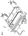
- FIG. 5 an example of a suitable construction for a hydrogen-processing assembly 10 that does not include a hydrogen-producing region is shown in an unassembled, exploded condition, and is generally indicated at 100.
- the enclosure of assembly 100 includes a first body portion 22 and a second body portion 24.
- hydrogen-separation assembly 28 is positioned in internal volume 16 so that the permeate region is defined between at least a portion of the perimeter 60 of the hydrogen-separation assembly and at least a portion of the inside perimeter 20 of the first body portion 22.
- the hydrogen-separation assembly is placed within the internal volume of the first body portion 16 so that it is in a spaced relation to the internal perimeter of the first body portion to define a permeate region therebetween. Then, the second body portion 24 is positioned at least partially within the opening to the first body portion 22 to compress the hydrogen-separation assembly within the internal volume. A seal weld or other suitable sealing mechanism or structure may then be applied at the interface of the body portions to create a fluid-tight interface.
- any suitable retention mechanism may be used to provide a fluid-tight interface between the body portions of the enclosure and to further provide a suitable amount of compression to the hydrogen-separation assembly within the enclosure, such as to provide and/or maintain internal seals and/or flow paths between and/or within the various components of the hydrogen-separation assembly.
- the non-exclusive illustrative example of enclosure 14 shown in Fig. 5 further includes an input port 36 for receiving a mixed gas stream for delivery to the mixed gas region of the internal volume, a product output port 46 for removal of the hydrogen-rich permeate stream, and a byproduct output port 50 for removal of byproduct gases.
- the non-exclusive illustrative example of a hydrogen-separation assembly 28 illustrated in Fig. 5 may be described as generally planar, and as schematically illustrated by the multiple arrows extending from the top and bottom (as viewed in Fig. 5 ) of the hydrogen-separation assembly, the hydrogen-rich, or permeate, stream exits the hydrogen-separation assembly in a direction generally parallel to the plane of the hydrogen-separation assembly. Stated differently, the permeate stream exits the hydrogen-separation assembly and enters the permeate region of the internal volume from a direction generally parallel to the plane of the hydrogen-separation assembly and the hydrogen-selective membranes located therein.
- gas distribution conduits 140 and 170 which define at least portions of the mixed gas region and which provided flow paths for the mixed gas and byproduct streams, respectively, through the hydrogen-separation assembly.
- the mixed gas stream enters the enclosure via inlet 36.
- the portion of the mixed gas stream that does not pass through the hydrogen-selective membranes (that is, the byproduct stream 52) is forced into distribution conduit 170 and then out byproduct outlet port 50.
- the portion of the mixed gas stream that does pass through the hydrogen-selective membranes forms permeate stream 48, which is forced into the permeate region of the internal volume and subsequently expelled from the enclosure via product output port 46.
- Enclosure 14 is also illustrated as including optional mounts 150, which may be used to position the enclosure 14 with respect to other components of a hydrogen generation system and/or fuel cell system, etc.
- first body portion 22 may include at least one projection, or guide, 146 that extends into internal volume 16 to align or otherwise position the hydrogen-separation region within the internal volume of the enclosure.
- guide 146 may be utilized in Fig. 5 , but it is within the scope of the present disclosure that no guides, one guide, or any number of guides may be utilized. When more than one guide is utilized, the guides may have the same or different sizes, shapes, and/or relative orientations within the enclosure.
- hydrogen-separation assembly 28 may include recesses 152 that are sized to receive the guides 146 of the body portion when the membrane assembly is inserted into internal volume 16. Stated differently, the recesses on the hydrogen-separation assembly are designed to align with the guides that extend into the enclosure's internal volume to position the hydrogen-separation assembly in a selected orientation within the compartment. Accordingly, the first body portion may be described as providing alignment guides for the hydrogen-separation assembly. In Fig. 5 , it can be seen that second body portion 24 may also include recesses 152. Recesses 152 may guide, or align, the first and second portions when the portions are assembled to form the enclosure. The illustrated guides and recesses are not required to all enclosures and/or hydrogen-separation assemblies and/or components thereof according to the present disclosure.
- a gas passage, or channel 176 exists between hydrogen-separation assembly 28 and the internal perimeter 20 to form at least a portion of the permeate region 34 of the internal volume.
- the size of passage 176 may vary within the scope of the present disclosure, and may be smaller than is depicted for the purpose of illustration.
- the hydrogen-rich gas, or permeate stream may flow through this passage and be withdrawn from the enclosure through the product output port.
- hydrogen-separation assemblies 28 may (but are not required to) include spacers, or protrusions, 124 that extend from at least a portion of the outside perimeter 60 and aid in positioning the hydrogen-separation assembly within the enclosure in its spaced relation as described herein.
- spacers 124 may be generally trapezoidal in shape and may extend from one or more of the various components that make up a hydrogen-separation assembly, although any suitable shape is within the scope of the present disclosure.
- spacers 124 may extend from one or more of the feed plates and/or sealing plates that may be incorporated into a hydrogen-separation assembly.
- the spacers may be (but are not require to be) less than the full thickness of the associated plate.
- spacers 124 do not extend across the entire thickness of the hydrogen-separation assembly so that they do riot block the flow of permeate gas within the permeate region 34.
- the spacers extend from the hydrogen-separation assembly to, or toward, the inside perimeter of the internal enclosure, and in some embodiments may extend into contact with the internal enclosure.
- spacers that extend from the inside perimeter 20 of the internal enclosure are equally within the scope of the present disclosure, and like spacers 124 may aid in the positioning of the hydrogen-separation assembly within the enclosure and thereby maintain the spaced relation between the two.
- Any suitable mechanism, component, and/or structure for maintaining the spaced relation between at least a portion of the outer perimeter of the hydrogen-separation assembly and the inside perimeter of the body of the enclosure is within the scope of the present disclosure.
- An optional groove 126 may extend into the first body portion 22 of the enclosure, as illustrated in Fig. 6 .
- Groove 126 may effectively enlarge the permeate region 34 and thereby aid in the flow of the permeate gas through gas passage 176 and thus permeate region 34 to the product output port 46 by increasing the space between at least a portion of the outer perimeter of the hydrogen-separation assembly and at least a portion of the inside perimeter of the body.
- the groove when present, may be described as defining at least a portion of a permeate gas passage through which permeate gas flows from the hydrogen-separation assembly to the product output port.
- the relative size of the channel 176, arid further the groove 126 may vary within the scope of the present disclosure from that depicted in Fig. 6 for the purpose of illustration.
- the various plates and gaskets that form a hydrogen-separation assembly may be sized with asymmetrical shapes so that these components may only be located in the enclosure in a predetermined configuration. This is not required, but it may assist in assembly of the components because they cannot be inadvertently positioned in the housing in a backwards or upside-drown configuration.
- a corner region 128 of the hydrogen-separation assembly has a different shape than the other corner regions, with this difference being sufficient to permit that corner to be only inserted into one of the corresponding corner regions of the enclosure's internal volume.
- the non-exclusive example illustrated in Fig. 7 incorporates a more squared-off corner than the other three corners of the hydrogen-separation assemblies illustrated herein, although any suitable shape of one or more corner regions that facilitate proper positioning of the hydrogen-separation assembly within an enclosure are within the scope of the present disclosure. Additionally or alternatively, regions other than the corner regions may facilitate the same functionality. Accordingly, some enclosures according to the present disclosure may be described as being keyed, or indexed, to define the orientation of the gaskets, frames, supports and similar components that are stacked therein.
- some hydrogen-separation assemblies and enclosures according to the present disclosure may be configured so that the spaced relation between the two does not extend around the entire perimeters thereof.
- the components that define a hydrogen-separation assembly and/or other components that may be housed within an enclosure according to the present disclosure may include an end region 130 that is shaped so as to not provide (or to at least minimally provide) a channel or space between the end region 130 and the inside perimeter 20 of the enclosure body.
- the hydrogen-separation assembly may thereby aid in the positioning and maintaining of the hydrogen-separation assembly (and/or other components) in a spaced relation to the inside perimeter of the body of the enclosure. Additionally or alternatively, such a configuration may aid in the directing of the permeate gas that enters the channel 176 from the harvesting regions of the membrane assemblies to the product output port of the enclosure. That is, because the hydrogen purification process according of the present disclosure is a pressure driven process, reducing the distance required that the permeate gas has to travel to exit the enclosure reduces the pressure drop associated therewith and thereby may provide for greater hydrogen flux, as discussed above.
- a hydrogen-processing assembly 10 that includes a hydrogen-producing region 70 is shown in an unassembled, exploded condition, and is generally indicated at 120.
- the hydrogen-processing assembly 120 illustrated in Fig. 7 further includes an input port 36 for receiving a feed stream 38 for delivery to hydrogen-producing region 70, and an access port 122 for loading and removing catalyst from the hydrogen-producing region.
- Assemblies 120 according to the present disclosure are not required to include a catalyst access port.
- access port 122 may be capped off or otherwise sealed.
- the second body portion 24 of assembly 120 is shown including an optional protrusion 123 that aligns generally with gas distribution conduit 140, and thereby may aid in the positioning of the hydrogen-separation assembly within the enclosure, in applying compression to the gas distribution conduits, and/or in maintaining the spaced relation between the hydrogen-separation assembly and the inside perimeter of the enclosure body.
- Second portion 24 may include more than one protrusion, or projecting rib, such as is illustrated in dashed lines at 123 to align generally with gas distribution conduit 170.
- the protrusion may be configured to extend only far enough into the internal volume to properly align with the hydrogen-separation assembly and not prevent the flow of mixed-gas through conduit 140 to and/or from the membrane assemblies and/or other components.
- assembly 154 includes a plurality of membrane assemblies 30 that include hydrogen-selective membranes 54.
- the illustrated assembly 28 includes a single-membrane assembly 88 and a double-membrane assembly 90. Also shown are various porous membrane supports, or screens, 162, that define the harvesting regions of the membrane assemblies.
- Membrane assemblies 30 include sealing gaskets 168 that extend proximate the membranes and screens, but not around the perimeters of the membranes and screens, to provide seals for the gas distribution conduits 140, 170.
- the mixed gas region of the internal volume is at least partially defined by the internal spaces of the various sealing gaskets and feed plates and by the gas distribution conduits 140 and 170. Accordingly, in application, a mixed gas stream enters the mixed gas region via the internal space of sealing gasket 212. A portion of the mixed gas stream then travels into the conduit 140 via feed plate 216 to be distributed to the single-membrane assembly 88 and the near side (as viewed in Fig.
- the portion of the mixed gas stream that does pass through the hydrogen-selective membranes to form the hydrogen-rich, or permeate, stream flows into the permeate region of the internal volume via screens 162 of membrane assemblies 30. Thereafter the permeate stream may be removed from the enclosure through the product output port.
- Fig. 9 Also illustrated in Fig. 9 are an optional catalyst retention plate 160 and sealing gasket 166 that may be used in hydrogen-processing assemblies according to the present disclosure that include a hydrogen-producing region 70, such as hydrogen-processing assembly 120 shown in Fig. 8 and discussed above.
- the catalyst retention plate 160 retains the catalyst material within the hydrogen-producing region.
- Feed stream 38 enters hydrogen-producing region 70 via input port 36, and percolates through the catalyst material to form the mixed gas stream, which in the illustrated example of Fig. 9 , enters the mixed gas region via slits or other apertures 167 in the retention plate.
- the mixed gas then travels through the hydrogen-separation assembly, as discussed above, to form both the permeate stream and the byproduct stream.
- FIG. 10 another illustrative, non-exclusive example of a suitable construction for a hydrogen-processing assembly 10 that does not include a hydrogen-producing region is shown in an unassembled, exploded condition, and is generally indicated at 180.
- Assembly 180 includes an optional hydrogen-polishing region 182 that further purifies the permeate stream subsequent to being formed by the hydrogen-separation assembly 28.
- the hydrogen-polishing region incorporates a methanation catalyst, or methanation catalyst bed, 185 within the enclosure and held in place between a catalyst support plate 184, which may take the form of a compressible pad or support, and the inside surface of the enclosure adjacent the product output port 46.
- an additional support plate 186 which may take the form of a screen, may also be provided to generally prevent the catalyst material from being expunged through the product output port along with the purified hydrogen. Accordingly, plate 186 may include one or more apertures, or holes, that permit the purified hydrogen to pass, while retaining the catalyst bed within the polishing region 182. In the illustrated example of Fig.
- the permeate stream upon exiting the hydrogen-separation assembly, enters the permeate region defined by the outer perimeter 60 of the hydrogen-separation assembly and the inside perimeter 20 of the enclosure body, and is pressure driven into the hydrogen-polishing region, where, as described in more detail herein, compositions that may be harmful to downstream components of a fuel cell system, such as carbon monoxide for example, may be removed by the catalyst bed.
- assembly 188 includes a plurality of membrane assemblies 30 that include hydrogen-selective membranes 54.
- Assembly 188 includes a single-membrane assembly 88 and a double-membrane assembly 90, both including porous membrane supports, or screens, 162, that define the harvesting regions of the membrane assemblies.
- the number and type of membrane assemblies in separation assemblies according to the present disclosure may vary, including more or less membrane assemblies than are shown in the illustrated graphical examples.
- 11 further include sealing gaskets 168 that extend proximate the membranes and screens, but not around the perimeters of the membranes and screens, to provide seals for the gas distribution conduits 190, 192, 194 that define a portion of the mixed gas region of the assembly.
- sealing gaskets 402, 404, 406, 408, 410, and 412, feed plates 414, 416, and sealing plate, or transition feed plate, 418 are also provided.
- the mixed gas region of the internal volume is at least partially defined by the internal spaces of the various sealing gaskets and feed plates and by the gas distribution conduits 190, 192, and 194.
- sealing plate 418 does not include a conduit passage on one end, thereby effectively separating gas conduits 190 and 194. Accordingly, in application, a mixed gas stream first enters the mixed gas region through gas conduit 190.
- the mixed gas stream then travels into the internal space of gasket 404 via feed passages 215 in feed plate 414, where it comes into contact with the mixed gas surface of the near (as viewed in Fig. 11 ) hydrogen-selective membrane 54 of the double-membrane assembly 90.
- the portion of the mixed gas stream that does not pass through the near membrane travels into gas conduit 192 via feed plate 414 where it is then distributed to the internal space of gaskets 406, 408, 410, and sealing plate 418 to come into contact with the mixed gas surface of the far (as viewed in Fig. 11 ) membrane 54 of double-membrane assembly 90 and the membrane 54 of the single-membrane assembly 88.
- the portion of the mixed gas stream that does not pass through any of the membranes 54 is pressure driven into gas conduit 194 via feed plate 416 to be expelled from the enclosure as a byproduct stream via the byproduct output port of the enclosure.
- the portion of the mixed gas stream that does pass through the hydrogen-selective membranes to form the hydrogen-rich or permeate stream flows into the permeate region of the internal volume via screens 162 of membrane assemblies 30. Thereafter the permeate stream may be removed from the enclosure through the product output port.
- the permeate stream is further purified in the hydrogen-polishing region, prior to exiting the enclosure via product output port 46.
- adhesive may (but is not required to) be used to secure the membranes 54 to the screen structures 162 and/or to secure the components of the screen structures, as discussed in more detail in U.S. Patent No. 6,319,306 , the entire disclosure of which is hereby incorporated for all purposes.
- An example of a suitable adhesive is sold by 3M under the trade name SUPER 77.
- the adhesive may be at least substantially, if not completely, removed after fabrication of the membrane assembly so as not to interfere with the permeability, selectivity and flow paths of the gases.
- An example of a suitable method for removing adhesive from the membranes and/or screen structures or other supports is by exposure to oxidizing conditions prior to initial operation of assembly 10. The objective of the oxidative conditioning is to burn out the adhesive without excessively oxidizing the membrane. A suitable procedure for such oxidizing is disclosed in U.S.
- screen members when utilized, may be otherwise secured together, such as by sintering, welding, brazing, diffusion bonding and/or with a mechanical fastener. It is also within the scope of the present disclosure that the screen members, when utilized, may not be coupled together other than by being compressed together in the hydrogen-separation assembly of a hydrogen-processing assembly.
- Screens 162 may (but are not required to) include a coating on the surfaces that engage the permeate surfaces of membranes 54. Examples of suitable coatings are disclosed in U.S. Patent No. 6,569,227 ,
- attachment mechanisms that achieve gas-tight seals between the various components forming membrane assemblies 30 and hydrogen-separation assemblies 28 include one or more of brazing, gasketing, and welding.
- gaskets, plates, and/or other components of membrane assemblies and/or hydrogen-separation assemblies discussed herein do not all need to be formed from the same materials and/or do not necessarily have the same dimensions, such as the same thicknesses.
- suitable gaskets include flexible graphite gaskets, including those sold under the trade name GRAFOILTM by Union Carbide, although other materials may be used, such as depending upon the operating conditions under which an assembly 10 is used.
- Various structural components may be formed from stainless steel or one or more other suitable structural materials discussed in the above-incorporated patents and applications.
- FIG. 12 An illustrative, non-exclusive example of a hydrogen-processing assembly 10 that is adapted to receive mixed gas stream 40 from a source of hydrogen gas to be purified is schematically illustrated in Fig. 12 .
- illustrative, non-exclusive examples of hydrogen sources are indicated generally at 302 and include a hydrogen-producing fuel processor 300 and a hydrogen storage device 306.
- a fuel processor is generally indicated at 300, and the combination of a fuel processor and a hydrogen-purification device, or hydrogen-processing assembly 10, may be referred to as a hydrogen-producing fuel-processing system 303.
- a heating assembly which may be provided to provide heat to assembly 10 and may take a variety of forms.
- Fuel processor 300 may take any suitable form including, but not limited to, the various forms of hydrogen-producing region 70 discussed above.
- the schematic representation of fuel processor 300 in Fig. 12 is meant to include any associated heating assemblies, feedstock delivery systems, air delivery systems, feed stream sources or supplies, etc.
- Illustrative, non-exclusive examples of suitable hydrogen storage devices 306 include hydride beds and pressurized tanks.
- Fuel processors are often operated at elevated temperatures and/or pressures. As a result, it may be desirable to at least partially integrate hydrogen-processing assembly 10 with fuel processor 300, as opposed to having assembly 10 and fuel processor 300 connected by external fluid transportation conduits.
- An example of such a configuration is shown in Fig. 13 , in which the fuel processor includes a shell or housing 312, which device 10 forms a portion of and/or extends at least partially within.
- fuel processor 300 may be described as including device 10. Integrating the fuel processor or other source of mixed gas stream 40 with hydrogen-processing assembly 10 enables the devices to be more easily moved as a unit. It also enables the fuel processing system's components, including assembly 10, to be heated by a common heating assembly and/or for at least some, if not all, of the heating requirements of assembly 10 to be satisfied by heat generated by processor 300.
- fuel processor 300 is any suitable device that produces a mixed gas stream containing hydrogen gas, and preferably a mixed gas stream that contains a majority of hydrogen gas.
- fuel processor 300 will describe fuel processor 300 as being adapted to receive a feed stream 316 containing a carbon-containing feedstock 318 and water 320, as shown in Fig. 14 .
- the fuel processor 300 may take other forms, and that feed stream 316 may have other compositions, such as containing only a carbon-containing feedstock or only water.
- Feed stream 316 may be delivered to fuel processor 300 via any suitable mechanism.
- a single feed stream 316 is shown in Fig. 14 , but it should be understood that more than one stream 316 may be used and that these streams may contain the same or different components.
- the feedstock may be delivered with the water component of feed stream 316, such as shown in Fig. 14 .
- the carbon-containing feedstock is immiscible or only slightly miscible with water, these components may be delivered to fuel processor 300 in separate streams, such as shown in dashed lines in Fig. 14 .
- feed stream 316 is shown being delivered to fuel processor 300 by a feed stream delivery system 317.
- Delivery system 317 includes any suitable mechanism, device, or combination thereof that delivers the feed stream to fuel processor 300.
- the delivery system may include one or more pumps that deliver the components of stream 316 from a supple.
- delivery system 317 may include a valve assembly adapted to regulate the flow of the components from a pressurized supply.
- the supplies may be located external the fuel cell system, or may be contained within or adjacent the system.
- fuel processor 300 includes a hydrogen-producing region in which mixed gas stream 40 is produced from feed stream 316.
- a variety of different processes may be utilized in the hydrogen-producing region.
- An example of such a process is steam reforming, in which region 332 includes a steam reforming catalyst 334.
- other hydrogen-producing mechanisms may be utilized without departing from the scope of the present disclosure.
- mixed gas stream 40 may also be referred to as a reformate stream:
- the fuel processor may be adapted to produce substantially pure hydrogen gas, or even pure hydrogen gas.
- substantially pure hydrogen gas may be greater than 90% pure, greater than 95% pure, greater than 99% pure, greater than 99.5% pure, or greater than 99.9% pure.
- suitable fuel processors are disclosed in U.S. Patent Nos. 6,221,117 and 6.319,306 , and U.S. Patent Application Publication No. 2001/0045061 .
- Fuel processor 300 may, but does not necessarily, further include a polishing region 348, such as shown in Fig. 14 .
- Polishing region 348 receives hydrogen-rich stream 48 from assembly 10 and further purifies the stream by reducing the concentration of, or removing, selected compositions therein.
- the resulting stream is indicated at 314 and may be referred to as a product hydrogen stream or purified hydrogen stream.
- hydrogen-rich stream 48 forms product hydrogen stream 314.
- compositions that may damage the fuel cell stack such as carbon monoxide and carbon dioxide, may be removed from the hydrogen-rich stream, it necessary.
- the concentration of carbon monoxide may be less than 10 ppm (parts per million) to prevent the control system from isolating the fuel cell stack.
- the system may limit the concentration of carbon monoxide to less than 5 ppm, or even less than 1 ppm.
- the concentration of carbon dioxide may be greater than that of carbon monoxide.
- concentrations of less than 25% carbon dioxide may be acceptable.
- the concentration of carbon dioxide may be less than 10%, or even less than 1%.
- Concentrations of carbon dioxide may be less than 50 ppm. It should be understood that the concentrations presented herein are illustrative examples, and that concentrations other than those presented herein may be used and are within the scope of the present disclosure. For example, particular users or manufacturers may require minimum or maximum concentration levels or ranges that are different than those identified herein.
- Region 348 includes any suitable structure for removing or reducing the concentration of the selected compositions in stream 48.
- PEM proton exchange membrane
- Bed 350 converts carbon monoxide and carbon dioxide into methane and water, both of which will not damage a PEM fuel cell stack.
- Polishing region 348 may also include another hydrogen-producing region 352, such as another reforming catalyst bed, to convert any unreacted feedstock into hydrogen gas.
- the second reforming catalyst bed may be upstream from the methanation catalyst bed so as not to reintroduce carbon dioxide or carbon monoxide downstream of the methanation catalyst bed.
- Steam reformers typically operate at temperatures in the range of 200o C and 900o C, and at pressures in the range of 50 psi and 1000 psi, although temperatures outside of this range are within the scope of the present disclosure, such as depending upon the particular type and configuration of fuel processor being used. Any suitable heating mechanism or device may be used to provide this heat, such as a heater, burner, combustion catalyst, or the like.
- the heating assembly may be external the fuel processor or may form a combustion chamber that forms part of the fuel processor.
- the fuel for the heating assembly may be provided by the fuel processing or fuel cell system, by an external source, or both.
- fuel processor 300 is shown including a shell 312 in which the above-described components are contained.
- Shell 312 which also may be referred to as a housing, enables the components of the fuel processor to be moved as a unit. It also protects the components of the fuel processor from damage by providing a protective enclosure and reduces the heating demand of the fuel processor because the components of the fuel processor may be heated as a unit.
- Shell 312 may, but does not necessarily, include insulating material 333, such as a solid insulating material, blanket insulating material, or an air-filled cavity. It is within the scope of the present disclosure, however, that the fuel processor may be formed without a housing or shell.
- the insulating material may be internal the shell, external the shell, or both.
- the fuel processor may further include an outer cover or jacket external the insulation.
- one or more of the components of fuel processor 300 may either extend beyond the shell or be located external at least shell 312.
- assembly 10 may extend at least partially beyond shell 312, as indicated in Fig. 13 .
- polishing region 348 may be external of shell 312 and/or a portion of hydrogen-producing region 332 (such as portions of one or more reforming catalyst beds) may extend beyond the shell.
- fuel processor 300 may be adapted to deliver hydrogen-rich stream 48 or product hydrogen stream 314 to at least one fuel cell stack, which produces an electric current therefrom.
- the fuel processor and fuel cell stack may be referred to as a fuel cell system.
- An example of such a system is schematically illustrated in Fig. 15 , in which a fuel cell stack is generally indicated at 322.
- the fuel cell stack is adapted to produce an electric current from the portion of product hydrogen stream 314 delivered thereto.
- a single fuel processor 300 and a single fuel cell stack 322 are shown and described, however, more than one of either or both of these components may be used. It should be understood that these components have been schematically illustrated and that the fuel cell system may include additional components that are not specifically illustrated in the figures, such as feed pumps, air delivery systems, heat exchangers, heating assemblies and the like.
- Fuel cell stack 322 contains at least one, and typically multiple, fuel cells 324 that are adapted to produce an electric current from the portion of the product hydrogen stream 314 delivered thereto. This electric current may be used to satisfy the energy demands, or applied load, of an associated energy-consuming device 325.
- Illustrative examples of devices 325 include, but should not be limited to, a motor vehicle, recreational vehicle, boat, tools, lights or lighting assemblies, appliances (such as a household or other appliance), household, signaling or communication equipment, etc. It should be understood that device 325 is schematically illustrated in Fig. 15 and is meant to represent one or more devices or collection of devices that are adapted to draw electric current from the fuel cell system.
- a fuel cell stack typically includes multiple fuel cells joined together between common end plates 323, which contain fluid delivery/removal conduits (not shown). Examples of suitable fuel cells include PEM fuel cells and alkaline fuel cells. Fuel cell stack 322 may receive all of product hydrogen stream 314. Some or all of stream 314 may additionally, or alternatively, be delivered, via a suitable conduit, for use in another hydrogen-consuming process, burned for fuel or heat, or stored for later use.
- the present disclosure including fuel-processing systems, hydrogen-processing assemblies, fuel cell systems, and components thereof, is applicable to the fuel-processing and other industries in which hydrogen gas is purified, produced and/or utilized.
Landscapes
- Chemical & Material Sciences (AREA)
- Chemical Kinetics & Catalysis (AREA)
- Organic Chemistry (AREA)
- Engineering & Computer Science (AREA)
- Inorganic Chemistry (AREA)
- Combustion & Propulsion (AREA)
- Sustainable Energy (AREA)
- Electrochemistry (AREA)
- General Chemical & Material Sciences (AREA)
- Life Sciences & Earth Sciences (AREA)
- Sustainable Development (AREA)
- Manufacturing & Machinery (AREA)
- Health & Medical Sciences (AREA)
- General Health & Medical Sciences (AREA)
- Separation Using Semi-Permeable Membranes (AREA)
- Hydrogen, Water And Hydrids (AREA)
- Fuel Cell (AREA)
Claims (18)
- Wasserstoff verarbeitende Anordnung (10), die Folgendes umfasst:ein Gehäuse (14), das Folgendes umfasst:einen Körper (16), der ein Innenvolumen (18) festlegt und wobei der Körper einen Innenumfang (20) aufweist, wobei das Innenvolumen einen Mischgasbereich (32) und einen Permeatbereich (34) umfasst;mindestens eine Eingangsöffnung (36), die sich durch den Körper ausdehnt und über die ein Flüssigkeitsstrom (38) in das Gehäuse geleitet wird;mindestens eine Produktausgangsöffnung (46), die sich durch den Körper ausdehnt und über die ein Permeatstrom (48) aus dem Permeatbereich abgeleitet wird; undmindestens eine Nebenproduktausgangsöffnung (50) die sich durch den Körper ausdehnt und über die ein Nebenproduktstrom (52) aus dem Mischgasbereich abgeleitet wird; undeine Anordnung für die Wasserstoffabtrennung (28), die im Innenvolumen mit Abstand zu mindestens einem Abschnitt des Innenumfangs (20) des Körpers des Gehäuses platziert ist, wobei die Anordnung für die Wasserstoffabtrennung mindestens eine ebene oder generell ebene wasserstoffselektive Membran (54) umfasst und einen Außenumfang (60) aufweist, welcher auf der Ebene der mindestens einen wasserstoffselektiven Membran gemessen wird, wobei die Anordnung für die Wasserstoffabtrennung geeignet ist, um einen Mischgasstrom (40), der Wasserstoffgas (42) und andere Gase (44) enthält, aufzunehmen und den Mischgasstrom in den Permeatstrom und den Nebenproduktstrom zu teilen, wobei der Permeatstrom mindestens eines der Folgenden aufweist: eine höhere Konzentration von Wasserstoffgas und eine niedrigere Konzentration der anderen Gase; und zusätzlich wobei der Nebenproduktstrom mindestens einen wesentlichen Anteil der anderen Gase enthält;wobei der Permeatbereich des Innenvolumens zwischen mindestens einem Großteil des Außenumfangs (60) der Anordnung für die Wasserstoffabtrennung und mindestens einem Abschnitt des Innenumfangs (20) des Körpers des Gehäuses festgelegt wird; optional wobei die Anordnung für die Wasserstoffabtrennung in Verbindung mit einem Brennstoffzellenstapel (322) geeignet ist, um mindestens einen Teil des Permeatstroms aufzunehmen.
- Wasserstoff verarbeitende Anordnung nach Anspruch 1, wobei der Permeatbereich im direkten Flüssigkeitsaustausch mit dem mindestens einen Abschnitt des Innenumfangs (20) des Körpers des Gehäuses steht.
- Wasserstoff verarbeitende Anordnung nach Anspruch 1 oder Anspruch 2, wobei der Außenumfang der Anordnung für die Wasserstoffabtrennung zwei generell gegenüberliegende Abschnitte (64, 66) umfasst; und
wobei der Permeatbereich zwischen mindestens zwei Abschnitten des Innenumfangs des Körpers und den zwei generell gegenüberliegenden Abschnitten des Außenumfangs der Anordnung für die Wasserstoffabtrennung festgelegt wird. - Wasserstoff verarbeitende Anordnung nach einem beliebigen der vorhergehenden Ansprüche, wobei die Anordnung für die Wasserstoffabtrennung eine Vielzahl von Ausbuchtungen (124) umfasst, die sich vom Außenumfang (60) der Anordnung für die Wasserstoffabtrennung zum Innenumfang des Gehäuses ausdehnen, um die Anordnung für die Wasserstoffabtrennung im Gehäuse zu platzieren.
- Wasserstoff verarbeitende Anordnung nach einem beliebigen der vorhergehenden Ansprüche, wobei der Körper des Gehäuses mindestens eine Innenausnehmung umfasst, die einen Gasführungsweg (176) für den Permeatstrom festlegt.
- Wasserstoff verarbeitende Anordnung nach einem beliebigen der vorhergehenden Ansprüche, wobei die Anordnung für die Wasserstoffabtrennung und der Körper des Gehäuses verkeilt sind, um nur eine Ausrichtung der Anordnung für die Wasserstoffabtrennung innerhalb des Gehäuses festzulegen.
- Wasserstoff verarbeitende Anordnung nach einem beliebigen der vorhergehenden Ansprüche, wobei der Körper des Gehäuses einen ersten Abschnitt und einen zweiten Abschnitt umfasst;
wobei die Anordnung für die Wasserstoffabtrennung zwischen den ersten und zweiten Abschnitten zusammengepresst wird; und
wobei der Abstand zwischen der Anordnung für die Wasserstoffabtrennung und dem mindestens einen Abschnitt des Innenumfangs des Körpers des Gehäuses über das Zusammenpressen zwischen den ersten und zweiten Abschnitten beibehalten wird. - Wasserstoff verarbeitende Anordnung nach einem beliebigen der vorhergehenden Ansprüche,
wobei der Flüssigkeitsstrom dem Mischgasstrom entspricht und in den Mischgasbereich geleitet wird;
wobei die mindestens eine wasserstoffselektive Membran eine erste Fläche (56), die geeignet ist, um von dem Mischgasstrom berührt zu werden und eine Permeatfläche (58) umfasst, die der ersten Fläche generell gegenüberliegt; und
wobei der Permeatstrom aus einem Teil des Mischgasstroms gebildet wird, der durch die wasserstoffselektive Membran zum Permeatbereich des Innenvolumens gelangt. - Wasserstoff verarbeitende Anordnung nach einem beliebigen der Ansprüche 1 bis 7, die zusätzlich einen Wasserstoff erzeugenden Bereich (70) umfasst, der in dem Gehäuse platziert ist;
wobei der Flüssigkeitsstrom (38) einem Zufuhrstrom (72) entspricht und zum Wasserstoff erzeugenden Bereich geleitet wird;
wobei der Zufuhrstrom im Wasserstoff erzeugenden Bereich chemisch reagiert, um daraus Wasserstoffgas in Form des Mischgasstroms (40) zu erzeugen und wobei der Mischgasstrom zum Mischgasbereich des Innenvolumens geleitet wird;
wobei die mindestens eine wasserstoffselektive Membran eine erste Fläche (56), die geeignet ist, um von dem Mischgasstrom berührt zu werden und eine Permeatfläche (58) umfasst, die der ersten Fläche generell gegenüberliegt; und
wobei der Permeatstrom aus einem Teil des Mischgasstroms gebildet wird, der durch die wasserstoffselektive Membran zum Permeatbereich des Innenvolumens gelangt. - Wasserstoff verarbeitende Anordnung nach einem beliebigen der vorhergehenden Ansprüche, wobei die Anordnung für die Wasserstoffabtrennung:generell eben ist und so konfiguriert ist, dass der Permeatstrom die Anordnung für die Wasserstoffabtrennung in einer Richtung verlässt, die generell parallel zur Anordnung für die Wasserstoffabtrennung verläuft und/oderso konfiguriert ist, dass der Permeatstrom die Anordnung für die Wasserstoffabtrennung in einer Richtung verlässt, die generell parallel zur wasserstoffselektiven Membran verläuft und/odergeeignet ist, um den Mischgasstrom aus einer ersten Richtung aufzunehmen und so konfiguriert ist, dass der Permeatstrom die Anordnung für die Wasserstoffabtrennung in einer zweiten Richtung verlässt, die generell senkrecht zur ersten Richtung verläuft.
- Wasserstoff verarbeitende Anordnung nach einem beliebigen der Ansprüche 1 bis 7 oder 10,
wobei die mindestens eine wasserstoffselektive Membran eine erste Fläche (56), die geeignet ist, um von dem Mischgasstrom berührt zu werden und eine Permeatfläche (58) umfasst, die der ersten Fläche generell gegenüberliegt;
wobei der Permeatstrom aus einem Teil des Mischgasstroms gebildet wird, der durch die wasserstoffselektive Membran zum Permeatbereich des Innenvolumens gelangt; und
wobei die Anordnung für die Wasserstoffabtrennung so konfiguriert ist, dass der Permeatstrom in einer Richtung von der Permeatfläche zum Permeatbereich strömt, die generell parallel zur Permeatfläche verläuft. - Wasserstoff verarbeitende Anordnung nach Anspruch 1,
wobei die mindestens eine wasserstoffselektive Membran eine erste Fläche (56), die geeignet ist, um von dem Mischgasstrom berührt zu werden und eine Permeatfläche (58) umfasst, die der ersten Fläche generell gegenüberliegt;
wobei der Permeatstrom aus einem Teil des Mischgasstroms gebildet wird, der durch die wasserstoffselektive Membran von der ersten Fläche zum Permeatbereich gelangt;
wobei die Anordnung für die Wasserstoffabtrennung mindestens einen Auffangbereich (78) umfasst, welcher an der Permeatfläche anliegt; und
wobei die Anordnung für die Wasserstoffabtrennung so konfiguriert ist, dass der Permeatstrom in einer Richtung durch den Auffangbereich strömt, die generell parallel zu der mindestens einen wasserstoffselektiven Membran verläuft;
optional wobei die Anordnung für die Wasserstoffabtrennung mindestens ein Sieb umfasst, das den Auffangbereich festlegt und zusätzlich wobei die Anordnung für die Wasserstoffabtrennung keine Dichtung zwischen der Permeatfläche und dem Sieb umfasst oder
optional wobei der mindestens eine Auffangbereich generell parallel zu der mindestens einen wasserstoffselektiven Membran verläuft und generell deckungsgleich mit der mindestens einen wasserstoffselektiven Membran ist oder
optional wobei die Anordnung für die Wasserstoffabtrennung keine Dichtung umfasst, die an der Permeatfläche anliegt. - Wasserstoff verarbeitende Anordnung nach Anspruch 1, wobei die Anordnung für die Wasserstoffabtrennung eine Vielzahl räumlich getrennter ebener oder generell ebener wasserstoffselektiver Membranen umfasst, wobei jede Membran eine erste Fläche (56), die geeignet ist, um von dem Mischgasstrom berührt zu werden und eine Permeatfläche (58) umfasst, die der ersten Fläche generell gegenüberliegt,
optional wobei die Vielzahl räumlich getrennter wasserstoffselektiver Membranen mindestens ein Paar wasserstoffselektiver Membranen mit ihren jeweiligen Permeatflächen umfasst, die sich generell gegenüberliegen und räumlich getrennt sind, um einen Auffangbereich festzulegen, durch welchen der Permeatstrom zum Permeatbereich des Innenvolumens strömt oder
optional wobei die Anordnung für die Wasserstoffabtrennung mindestens ein Sieb umfasst, das den Auffangbereich festlegt und zusätzlich wobei die Anordnung für die Wasserstoffabtrennung keine Dichtung umfasst, die sich zwischen den Permeatflächen des mindestens einen Paares wasserstoffselektiver Membranen ausdehnt,
zusätzlich optional wobei die Vielzahl räumlich getrennter wasserstoffselektiver Membranen mindestens eine dritte wasserstoffselektive Membran umfasst, deren erste Fläche generell der ersten Fläche einer der wasserstoffselektiven Membranen des Paars der wasserstoffselektiven Membranen gegenüberliegt und davon räumlich getrennt ist. - Wasserstoff verarbeitende Anordnung nach Anspruch 1, die zusätzlich ein Katalysatorbett für die Methanisierung (185) im Gehäuse umfasst.
- Wasserstoff verarbeitende Anordnung nach Anspruch 1 in Verbindung mit einem Wasserstoff erzeugenden Bereich (70), der geeignet ist, um den Mischgasstrom zu erzeugen.
- Wasserstoff verarbeitende Anordnung nach Anspruch 15, wobei der Wasserstoff erzeugende Bereich mindestens ein Reformierungskatalysatorbett (334) umfasst,
optional wobei der Wasserstoff erzeugende Bereich im Bezug auf das Gehäuse entweder außen oder innen ist,
zusätzlich optional wobei die Wasserstoff verarbeitende Anordnung in zusätzlicher Verbindung mit einem Brennstoffzellenstapel (322) steht, der geeignet ist, um mindestens einen Teil des Permeatstroms aufzunehmen und daraus einen elektrischen Strom zu erzeugen. - Verwendung der Wasserstoff verarbeitenden Anordnung (10) nach Anspruch 1 für die Reinigung von Wasserstoffgas (42), wobei die Anordnung für die Wasserstoffabtrennung zusätzlich Folgendes umfasst:mindestens ein generell ebenes Membranmodul, das den Außenumfang (60) aufweist und das mindestens eine ebene oder generell ebene wasserstoffselektive Membran (54) und mindestens einen Auffangbereich (78) umfasst, welcher an der mindestens einen wasserstoffselektiven Membran anliegt, wobei die mindestens eine wasserstoffselektive Membran eine erste Fläche (56), die geeignet ist, um von dem Mischgasstrom berührt zu werden und eine Permeatfläche (58) umfasst, die der ersten Fläche generell gegenüberliegt und zusätzlich wobei der Permeatstrom aus einem Teil des Mischgasstroms gebildet wird, der durch die wasserstoffselektive Membran zum Auffangbereich (78) des Innenvolumens strömt, wobei der Auffangbereich eine Stütze umfasst, die geeignet ist, um die Permeatfläche der wasserstoffselektiven Membran abzustützen, wobei die Wasserstoff verarbeitende Anordnung keine Dichtung zwischen der wasserstoffselektiven Membran und der Stütze umfasst und zusätzlich wobei der Permeatbereich im direkten Flüssigkeitsaustausch mit dem mindestens einen Abschnitt des Innenumfangs des Körpers des Gehäuses steht;optional wobei der mindestens eine Auffangbereich generell parallel zu der mindestens einen wasserstoffselektiven Membran verläuft oderoptional wobei der mindestens eine Auffangbereich generell deckungsgleich mit der mindestens einen wasserstoffselektiven Membran ist.
- Verwendung der Wasserstoff verarbeitenden Anordnung (10) nach Anspruch 1 für die Reinigung von Wasserstoffgas (42), wobei die Anordnung für die Wasserstoffabtrennung zusätzlich Folgendes umfasst:mindestens ein Paar generell gegenüberliegender ebener oder generell ebener wasserstoffselektiver Membranen (54), wobei jede der wasserstoffselektiven Membranen eine erste Fläche (56), die geeignet ist, um von dem Mischgasstrom berührt zu werden und eine Permeatfläche (58) umfasst, die der ersten Fläche generell gegenüberliegt und zusätzlich wobei der Permeatstrom aus einem Teil des Mischgasstroms gebildet wird, der durch die wasserstoffselektiven Membranen zum Permeatbereich des Innenvolumens strömt; undwobei die Anordnung für die Wasserstoffabtrennung keine Dichtung umfasst, die sich zwischen den Permeatflächen des Paares generell gegenüberliegender wasserstoffselektiver Membranen ausdehnt.
Applications Claiming Priority (3)
| Application Number | Priority Date | Filing Date | Title |
|---|---|---|---|
| US80271606P | 2006-05-22 | 2006-05-22 | |
| US11/750,806 US7972420B2 (en) | 2006-05-22 | 2007-05-18 | Hydrogen-processing assemblies and hydrogen-producing systems and fuel cell systems including the same |
| PCT/US2007/012289 WO2007139829A1 (en) | 2006-05-22 | 2007-05-22 | Hydrogen-processing assemblies and hydrogen-producing systems and fuel cell systems including the same |
Publications (3)
| Publication Number | Publication Date |
|---|---|
| EP2033256A1 EP2033256A1 (de) | 2009-03-11 |
| EP2033256A4 EP2033256A4 (de) | 2011-11-09 |
| EP2033256B1 true EP2033256B1 (de) | 2015-07-29 |
Family
ID=38710677
Family Applications (1)
| Application Number | Title | Priority Date | Filing Date |
|---|---|---|---|
| EP07795232.3A Active EP2033256B1 (de) | 2006-05-22 | 2007-05-22 | Wasserstoffverarbeitende baugruppen und wasserstofferzeugende systeme und brennstoffzellensysteme damit |
Country Status (11)
| Country | Link |
|---|---|
| US (2) | US7972420B2 (de) |
| EP (1) | EP2033256B1 (de) |
| JP (1) | JP5037608B2 (de) |
| KR (1) | KR101095124B1 (de) |
| CA (1) | CA2658845C (de) |
| DK (1) | DK2033256T3 (de) |
| ES (1) | ES2548436T3 (de) |
| MX (1) | MX2008014950A (de) |
| MY (1) | MY148203A (de) |
| TW (1) | TWI351125B (de) |
| WO (1) | WO2007139829A1 (de) |
Families Citing this family (28)
| Publication number | Priority date | Publication date | Assignee | Title |
|---|---|---|---|---|
| US7972420B2 (en) * | 2006-05-22 | 2011-07-05 | Idatech, Llc | Hydrogen-processing assemblies and hydrogen-producing systems and fuel cell systems including the same |
| US8163064B2 (en) * | 2006-09-29 | 2012-04-24 | Sinvent As | Leak-proof membrane element and method of manufacturing such an element |
| US8465569B2 (en) * | 2008-09-16 | 2013-06-18 | Protonex Technology Corporation | Membrane support module for permeate separation in a fuel cell |
| US8449649B2 (en) | 2010-05-11 | 2013-05-28 | Idatech, Llc | Systems and methods for starting up pressure swing adsorption assemblies and hydrogen-producing fuel processing systems including the same |
| US8920996B2 (en) | 2010-05-11 | 2014-12-30 | Dcns | Systems and methods for regulating fuel cell air flow during low loads or cold temperature operation |
| WO2012067612A1 (en) * | 2010-11-17 | 2012-05-24 | Azur Energy Llc | Hydrogen purifier |
| JP5831888B2 (ja) * | 2010-12-14 | 2015-12-09 | 国立研究開発法人産業技術総合研究所 | 水素分離装置 |
| US8920732B2 (en) | 2011-02-15 | 2014-12-30 | Dcns | Systems and methods for actively controlling steam-to-carbon ratio in hydrogen-producing fuel processing systems |
| US8961627B2 (en) | 2011-07-07 | 2015-02-24 | David J Edlund | Hydrogen generation assemblies and hydrogen purification devices |
| WO2013086190A1 (en) | 2011-12-06 | 2013-06-13 | Hy9 Corporation | Catalyst-containing reactor system and associated methods |
| US20140065020A1 (en) | 2012-08-30 | 2014-03-06 | David J. Edlund | Hydrogen generation assemblies |
| US11738305B2 (en) | 2012-08-30 | 2023-08-29 | Element 1 Corp | Hydrogen purification devices |
| US9187324B2 (en) * | 2012-08-30 | 2015-11-17 | Element 1 Corp. | Hydrogen generation assemblies and hydrogen purification devices |
| US10717040B2 (en) | 2012-08-30 | 2020-07-21 | Element 1 Corp. | Hydrogen purification devices |
| CN107265403B (zh) | 2013-03-14 | 2020-03-03 | 浙江本德新能源科技有限公司 | 制氢装置和氢纯化设备 |
| US20140318372A1 (en) * | 2013-04-28 | 2014-10-30 | Greenbelt Resources Corporation | Membrane Separation Modules |
| WO2016178849A1 (en) * | 2015-05-01 | 2016-11-10 | Ballard Fuel Cell Systems Inc. | Membrane-based hydrogen purifiers |
| US10476093B2 (en) | 2016-04-15 | 2019-11-12 | Chung-Hsin Electric & Machinery Mfg. Corp. | Membrane modules for hydrogen separation and fuel processors and fuel cell systems including the same |
| US11351724B2 (en) | 2017-10-03 | 2022-06-07 | General Electric Company | Selective sintering additive manufacturing method |
| TWI724933B (zh) | 2018-01-04 | 2021-04-11 | 美商1號組件公司 | 氫氣淨化裝置 |
| US11177494B2 (en) | 2018-03-05 | 2021-11-16 | H2 Powertech, Llc | Systems and methods for forming a liquid mixture having a predetermined mix ratio and reforming systems, reforming methods, fuel cell systems, and fuel cell methods that utilize the liquid mixture |
| US11316180B2 (en) | 2020-05-21 | 2022-04-26 | H2 Powertech, Llc | Hydrogen-producing fuel cell systems and methods of operating hydrogen-producing fuel cell systems for backup power operations |
| US11712655B2 (en) | 2020-11-30 | 2023-08-01 | H2 Powertech, Llc | Membrane-based hydrogen purifiers |
| EP4250070A1 (de) | 2022-03-25 | 2023-09-27 | BIC Violex Single Member S.A. | Schreibinstrument |
| US12283727B2 (en) | 2022-08-16 | 2025-04-22 | H2 Powertech, Llc | Hydrogen-producing fuel cell systems and methods of operating the same |
| CN116173687B (zh) * | 2023-03-02 | 2025-12-16 | 北京东方华氢科技有限公司 | 一种提纯器及气体制备装置 |
| US20240399297A1 (en) * | 2023-06-02 | 2024-12-05 | Element 1 Corp | Hydrogen purification devices |
| US20240399295A1 (en) * | 2023-06-02 | 2024-12-05 | Element 1 Corp | Hydrogen purification devices |
Family Cites Families (281)
| Publication number | Priority date | Publication date | Assignee | Title |
|---|---|---|---|---|
| US1306221A (en) | 1919-06-10 | Etom emiis | ||
| US1848466A (en) * | 1932-03-08 | of terre haute | ||
| US1782824A (en) | 1928-05-18 | 1930-11-25 | Chemical Construction Corp | Catalytic apparatus |
| US2132151A (en) | 1935-03-13 | 1938-10-04 | Pennsylvania Petroleum Res Cor | Apparatus for treating mineral oils |
| US2450804A (en) | 1943-12-09 | 1948-10-05 | Phillips Petroleum Co | Catalyst chamber construction |
| US2609059A (en) * | 1948-06-29 | 1952-09-02 | Hydrocarbon Research Inc | Mass diffusion process and apparatus |
| US2824620A (en) * | 1955-09-12 | 1958-02-25 | Universal Oil Prod Co | Purification of hydrogen utilizing hydrogen-permeable membranes |
| US2958391A (en) * | 1958-02-24 | 1960-11-01 | Universal Oil Prod Co | Purification of hydrogen utilizing hydrogen-permeable membranes |
| US3094391A (en) | 1960-04-22 | 1963-06-18 | Kellogg M W Co | Hydrocarbon conversion |
| US3144312A (en) | 1961-06-06 | 1964-08-11 | Mertens Carl | Catalytic conversion plant for the continuous generation of gases of any kind out of ydrocarbons |
| US3208198A (en) | 1962-07-26 | 1965-09-28 | Engelhard Ind Inc | Method for hydrogen diffusion |
| DE1252633B (de) | 1963-08-31 | 1967-10-26 | Japan Pure Hydrogen Co , Ltd , Yokohama (Japan) | Vorrichtung zum Abtrennen reiner Gase durch Diffusion |
| US3338681A (en) | 1963-12-18 | 1967-08-29 | Union Carbide Corp | Apparatus for hydrogen generation |
| US3350176A (en) | 1964-03-24 | 1967-10-31 | Engelhard Ind Inc | Hydrogen generator |
| US3356538A (en) | 1964-09-29 | 1967-12-05 | Gen Electric | Electrodeposited ion exchange membrane and method of forming |
| US3336730A (en) | 1964-11-17 | 1967-08-22 | Union Carbide Corp | Hydrogen continuous production method and apparatus |
| US3469372A (en) | 1965-06-18 | 1969-09-30 | Mitsubishi Gas Chemical Co | Hydrogen permeable membrane and hydrogen permeating assembly |
| US3428476A (en) * | 1965-06-22 | 1969-02-18 | Engelhard Min & Chem | Method for producing hydrogen diffusion cells |
| US3344586A (en) | 1965-06-22 | 1967-10-03 | Engelhard Ind Inc | Gas separation apparatus |
| US3522019A (en) | 1965-08-03 | 1970-07-28 | United Aircraft Corp | Apparatus for generating hydrogen from liquid hydrogen - containing feedstocks |
| US3450500A (en) | 1965-08-03 | 1969-06-17 | United Aircraft Corp | Method for catalytically reforming hydrogen-containing carbonaceous feed-stocks by simultaneous abstractions through a membrane selectively permeable to hydrogen |
| US3368329A (en) * | 1965-08-10 | 1968-02-13 | Eguchi Takashi | Hydrogen purification apparatus |
| US3447288A (en) | 1965-08-23 | 1969-06-03 | Prototeck Inc | Gas-diffusion assembly including thin hydrogen-permeable impervious foil |
| US3524819A (en) | 1967-03-03 | 1970-08-18 | Lummus Co | Steam reforming of hydrocarbons |
| US3439474A (en) * | 1967-08-17 | 1969-04-22 | Union Carbide Corp | Method for hydrogen separation and purification |
| US3469944A (en) | 1968-05-13 | 1969-09-30 | Joseph P Bocard | Process and apparatus for the manufacture of hydrogen for fuel cells |
| US3486301A (en) | 1968-08-05 | 1969-12-30 | Engelhard Min & Chem | Hydrogen diffusion apparatus |
| US3520803A (en) | 1968-12-24 | 1970-07-21 | Ionics | Membrane fluid separation apparatus and process |
| US3655448A (en) * | 1969-05-22 | 1972-04-11 | United Aircraft Corp | Hydrogen generator desulfurizer employing feedback ejector |
| US3589171A (en) | 1969-08-25 | 1971-06-29 | California Inst Of Techn | Gas analysis system and palladium tube separator therefor |
| AT325082B (de) * | 1970-01-04 | 1975-10-10 | Vnii Prirodnykh Gazov | Reformator zur beheizung eines strahlungsofens und betriebsweise dieses reformators |
| US3564819A (en) * | 1970-02-24 | 1971-02-23 | Gen Electric | Membrane package construction |
| US3791106A (en) * | 1970-09-24 | 1974-02-12 | California Inst Of Techn | Gas analysis systems and palladium tube separator therefor |
| US3665680A (en) * | 1970-12-18 | 1972-05-30 | Engelhard Min & Chem | Hydrogen diffusion apparatus |
| US3713270A (en) * | 1971-05-24 | 1973-01-30 | Nat Res Dev | Hydrogen diffusion membranes |
| BE788610A (fr) | 1971-09-09 | 1973-03-08 | Rhone Poulenc Sa | Appareil separateur a membranes utilisable en permeation gazeuse et en pervaporation |
| US3782904A (en) * | 1971-10-07 | 1974-01-01 | Nasa | Compact hydrogenator |
| US4084934A (en) * | 1972-02-05 | 1978-04-18 | Mitsubishi Precision Co., Ltd. | Combustion apparatus |
| US3849076A (en) | 1972-06-21 | 1974-11-19 | V Gryaznov | Catalytic reactor for carrying out conjugate chemical reactions |
| US3761382A (en) | 1972-06-21 | 1973-09-25 | Triangle Environment Corp | Ers and the like apparatus for generating purifying and delivering hydrogen for analyz |
| FR2207747B1 (de) * | 1972-11-24 | 1975-07-04 | Rhone Poulenc Ind | |
| BE795954A (fr) * | 1973-02-05 | 1973-08-27 | Uralsky Politekhn Inst | Procede d'obtention de l'hydrogene de tres grande purete |
| US3839110A (en) | 1973-02-20 | 1974-10-01 | Bell Telephone Labor Inc | Chemical etchant for palladium |
| US3955941A (en) | 1973-08-20 | 1976-05-11 | California Institute Of Technology | Hydrogen rich gas generator |
| US3980452A (en) | 1973-09-14 | 1976-09-14 | Metallgesellschaft Aktiengesellschaft | Process for supplying heat to chemical reactions |
| US3920416A (en) | 1973-12-26 | 1975-11-18 | California Inst Of Techn | Hydrogen-rich gas generator |
| US3982910A (en) | 1974-07-10 | 1976-09-28 | The United States Of America As Represented By The Administrator Of The National Aeronautics And Space Administration | Hydrogen-rich gas generator |
| US4127393A (en) | 1975-01-13 | 1978-11-28 | British Gas Corporation | Method and apparatus for vaporizing hydrocarbon based liquids |
| US4072625A (en) | 1975-03-03 | 1978-02-07 | Imperial Chemical Industries Limited | Steam-hydrocarbon process |
| US4003343A (en) * | 1975-04-04 | 1977-01-18 | Phillips Petroleum Company | Method and apparatus for maintaining the operating temperature in a device for reducing engine exhaust pollutants |
| US3972695A (en) | 1975-05-12 | 1976-08-03 | Trienco, Inc. | Hydrogen purifier |
| US4003725A (en) * | 1975-05-12 | 1977-01-18 | Trienco, Inc. | Apparatus for purifying hydrogen gas |
| GB1525017A (en) | 1975-09-29 | 1978-09-20 | British Gas Corp | Steam reforming and methanation catalysts methods of making them and processes for the production of fuel gases |
| US4078985A (en) * | 1975-11-21 | 1978-03-14 | Nippon Soken, Inc. | Hydrogen generator |
| US4302177A (en) | 1976-03-26 | 1981-11-24 | The M. W. Kellogg Company | Fuel conversion apparatus and method |
| DE2614673C3 (de) * | 1976-04-05 | 1981-06-25 | Siemens AG, 1000 Berlin und 8000 München | Startvorrichtung für einen Spaltgasgenerator |
| US4056373A (en) | 1976-05-12 | 1977-11-01 | Resource Systems, Inc. | Hydrogen-purification apparatus with palladium-alloy filter coil |
| US4098960A (en) | 1976-12-27 | 1978-07-04 | United Technologies Corporation | Fuel cell fuel control system |
| US4098959A (en) | 1976-12-27 | 1978-07-04 | United Technologies Corporation | Fuel cell fuel control system |
| US4132668A (en) * | 1977-04-06 | 1979-01-02 | Gryaznov Vladimir M | Method of preparing a hydrogen-permeable membrane catalyst on a base of palladium or its alloys for the hydrogenation of unsaturated organic compounds |
| US4175165A (en) | 1977-07-20 | 1979-11-20 | Engelhard Minerals & Chemicals Corporation | Fuel cell system utilizing ion exchange membranes and bipolar plates |
| CH625712A5 (de) * | 1977-12-01 | 1981-10-15 | Kilcher Chemie Ag | |
| US4329157A (en) | 1978-05-16 | 1982-05-11 | Monsanto Company | Inorganic anisotropic hollow fibers |
| US4254086A (en) * | 1978-12-27 | 1981-03-03 | Sanders Alfred P | Endothermal water decomposition unit for producing hydrogen and oxygen |
| US4214969A (en) | 1979-01-02 | 1980-07-29 | General Electric Company | Low cost bipolar current collector-separator for electrochemical cells |
| US4468235A (en) | 1979-02-15 | 1984-08-28 | Hill Eugene F | Hydrogen separation using coated titanium alloys |
| US4197152A (en) * | 1979-03-14 | 1980-04-08 | Gte Sylvania Incorporated | Attaching self-supporting emissive film to cathode support |
| US4248688A (en) * | 1979-09-04 | 1981-02-03 | International Business Machines Corporation | Ion milling of thin metal films |
| US4331520A (en) | 1979-10-26 | 1982-05-25 | Prototech Company | Process for the recovery of hydrogen-reduced metals, ions and the like at porous hydrophobic catalytic barriers |
| DE2949011A1 (de) | 1979-12-06 | 1981-06-11 | Varta Batterie Ag, 3000 Hannover | Verfahren und vorrichtung zur elektrochemischen energiegewinnung |
| US4319923A (en) * | 1979-12-26 | 1982-03-16 | Western Electric Co., Inc. | Recovery of gold and/or palladium from an iodide-iodine etching solution |
| US4567857A (en) * | 1980-02-26 | 1986-02-04 | The United States Of America As Represented By The Administrator Of The National Aeronautics And Space Administration | Combustion engine system |
| GB2072216A (en) | 1980-03-18 | 1981-09-30 | British Gas Corp | Treatment of hydrocarbon feedstocks |
| US4381641A (en) | 1980-06-23 | 1983-05-03 | Gulf Research & Development Company | Substoichiometric combustion of low heating value gases |
| US4313013A (en) * | 1980-08-01 | 1982-01-26 | Phillips Petroleum Company | Palladium or a palladium alloy hydrogen diffusion membrane treated with a volatile compound of silicon is used to separate hydrogen from a mixture of it with a hydrocarbon |
| US4387434A (en) | 1980-10-24 | 1983-06-07 | Process Technologies, Inc. | Intelligent field interface device for fluid storage facility |
| US4315893A (en) * | 1980-12-17 | 1982-02-16 | Foster Wheeler Energy Corporation | Reformer employing finned heat pipes |
| US4430304A (en) * | 1981-11-13 | 1984-02-07 | The United States Of America As Represented By The United States Department Of Energy | Slab reformer |
| US4504447A (en) * | 1981-11-13 | 1985-03-12 | The United States Of America As Represented By The United States Department Of Energy | Slab reformer |
| US4422911A (en) | 1982-06-14 | 1983-12-27 | Prototech Company | Method of recovering hydrogen-reduced metals, ions and the like at porous catalytic barriers and apparatus therefor |
| US4444158A (en) * | 1982-09-03 | 1984-04-24 | Conoco Inc. | Alcohol dissociation process for automobiles |
| DE3370594D1 (de) | 1982-09-13 | 1987-05-07 | Johnson Matthey Plc | Diffusion cell |
| US4466253A (en) | 1982-12-23 | 1984-08-21 | General Electric Company | Flow control at flash tank of open cycle vapor compression heat pumps |
| US4473622A (en) | 1982-12-27 | 1984-09-25 | Chludzinski Paul J | Rapid starting methanol reactor system |
| JPS59213601A (ja) * | 1983-05-19 | 1984-12-03 | Mitsubishi Electric Corp | 燃料電池の改質反応制御装置 |
| US4472176A (en) | 1983-08-01 | 1984-09-18 | Resource Systems, Inc. | Apparatus and method for the production of pure hydrogen from a hydrogen-containing crude gas |
| DE3332346A1 (de) | 1983-09-08 | 1985-04-04 | Kernforschungsanlage Jülich GmbH, 5170 Jülich | Wasserstoff-permeationswand, verfahren zur herstellung derselben und deren verwendung |
| DE3332345C2 (de) * | 1983-09-08 | 1986-08-07 | Doduco KG Dr. Eugen Dürrwächter, 7530 Pforzheim | Filtermaterial aus Metallgewebe |
| DE3332348A1 (de) | 1983-09-08 | 1985-04-04 | Kernforschungsanlage Jülich GmbH, 5170 Jülich | Wasserstoff-permeationswand |
| US4553981A (en) | 1984-02-07 | 1985-11-19 | Union Carbide Corporation | Enhanced hydrogen recovery from effluent gas streams |
| US4650814A (en) * | 1984-03-07 | 1987-03-17 | Keller Arnold P | Process for producing methanol from a feed gas |
| DE3424208A1 (de) | 1984-06-30 | 1986-01-16 | Kernforschungsanlage Jülich GmbH, 5170 Jülich | Verfahren und vorrichtung zur umsatzsteigerung von mit wasserstoffbildung ablaufenden gasreaktionen |
| US4613436A (en) | 1984-10-31 | 1986-09-23 | Separex Corporation | Membrane assembly for fluid separations-disk |
| US4533607A (en) | 1984-12-06 | 1985-08-06 | United Technologies Corporation | Process for removing electrolyte vapor from fuel cell exhaust gas |
| US4659634A (en) * | 1984-12-18 | 1987-04-21 | Struthers Ralph C | Methanol hydrogen fuel cell system |
| US4654063A (en) * | 1984-12-21 | 1987-03-31 | Air Products And Chemicals, Inc. | Process for recovering hydrogen from a multi-component gas stream |
| US4644751A (en) * | 1985-03-14 | 1987-02-24 | Massachusetts Institute Of Technology | Integrated fuel-cell/steam plant for electrical generation |
| JPS61233976A (ja) * | 1985-04-10 | 1986-10-18 | Fuji Electric Co Ltd | 燃料電池設備 |
| JPS61236601A (ja) | 1985-04-10 | 1986-10-21 | Hitachi Ltd | 燃料電池システム用の水蒸気改質装置 |
| JPH0665053B2 (ja) | 1985-04-22 | 1994-08-22 | 株式会社日立製作所 | 燃料電池システム |
| US4946667A (en) | 1985-06-10 | 1990-08-07 | Engelhard Corporation | Method of steam reforming methanol to hydrogen |
| US4670359A (en) | 1985-06-10 | 1987-06-02 | Engelhard Corporation | Fuel cell integrated with steam reformer |
| EP0349011A1 (de) * | 1985-06-27 | 1990-01-03 | Stone & Webster Engineering Corporation | Konvektionsreformieranlage für die Synthesegasherstellung |
| JPS62143801A (ja) * | 1985-12-18 | 1987-06-27 | Agency Of Ind Science & Technol | 水素吸蔵用合金による水素ガスの精製方法 |
| JP2511866B2 (ja) * | 1986-02-07 | 1996-07-03 | 株式会社日立製作所 | 燃料電池発電システム及びその起動方法 |
| JPS62143801U (de) | 1986-03-06 | 1987-09-10 | ||
| ES2019383B3 (es) | 1986-05-27 | 1991-06-16 | Ici Plc | Metodo para iniciar un proceso para la produccion de una corriente gaseosa que contiene hidrogeno y oxidos de carbono. |
| US4684581A (en) | 1986-07-10 | 1987-08-04 | Struthers Ralph C | Hydrogen diffusion fuel cell |
| US4810485A (en) * | 1986-08-25 | 1989-03-07 | Institute Of Gas Technology | Hydrogen forming reaction process |
| US4751151A (en) | 1986-12-08 | 1988-06-14 | International Fuel Cells Corporation | Recovery of carbon dioxide from fuel cell exhaust |
| JPH0642940B2 (ja) | 1987-03-31 | 1994-06-08 | 東洋エンジニアリング株式会社 | 気体吸熱反応用装置 |
| JPH07115841B2 (ja) | 1987-06-29 | 1995-12-13 | 日本酸素株式会社 | メタノ−ルの水蒸気改質法 |
| US4904548A (en) * | 1987-08-03 | 1990-02-27 | Fuji Electric Co., Ltd. | Method for controlling a fuel cell |
| US4781241A (en) | 1987-08-27 | 1988-11-01 | International Fuel Cells Corporation | Heat exchanger for fuel cell power plant reformer |
| DE68909979D1 (de) | 1988-03-24 | 1993-11-25 | Ici Plc | Zweistufiges Dampfreformierungsverfahren. |
| US5032365A (en) | 1988-06-14 | 1991-07-16 | Mitsubishi Denki Kabushiki Kaisha | Reaction apparatus |
| US4880040A (en) | 1988-09-16 | 1989-11-14 | Raymond Pierson | Liquid petroleum confinement system |
| FR2637817B1 (fr) * | 1988-10-17 | 1992-10-09 | Eurodia Sa | Cadre separateur pour dispositifs d'echange entre deux fluides |
| USRE35002E (en) | 1988-10-28 | 1995-07-25 | Yamaha Hatsudoki Kabushiki Kaisha | Fuel cell system |
| US5174900A (en) | 1989-03-24 | 1992-12-29 | The Standard Oil Company | Apparatus for separation and for treatment of fluid feedstreams, wafers for use therein and related methods |
| JPH0317026A (ja) | 1989-06-13 | 1991-01-25 | Agency Of Ind Science & Technol | 脱水素反応方法 |
| NL8902565A (nl) | 1989-10-16 | 1991-05-16 | Amafilter Bv | Inrichting voor membraanfiltratie. |
| US4981676A (en) * | 1989-11-13 | 1991-01-01 | Minet Ronald G | Catalytic ceramic membrane steam/hydrocarbon reformer |
| US5229102A (en) | 1989-11-13 | 1993-07-20 | Medalert, Inc. | Catalytic ceramic membrane steam-hydrocarbon reformer |
| US5354547A (en) | 1989-11-14 | 1994-10-11 | Air Products And Chemicals, Inc. | Hydrogen recovery by adsorbent membranes |
| FR2655873B1 (fr) | 1989-12-20 | 1992-04-10 | Medal Lp | Procede et dispositif d'elimination par permeation du monoxyde de carbone dans un melange gazeux a base d'hydrogene. |
| JPH03232703A (ja) | 1989-12-26 | 1991-10-16 | Tokyo Electric Power Co Inc:The | 炭化水素の改質装置 |
| US5051113A (en) | 1990-06-13 | 1991-09-24 | Du Pont Canada Inc. | Air-intake system for mobile engines |
| US5215729A (en) | 1990-06-22 | 1993-06-01 | Buxbaum Robert E | Composite metal membrane for hydrogen extraction |
| US5498278A (en) * | 1990-08-10 | 1996-03-12 | Bend Research, Inc. | Composite hydrogen separation element and module |
| US5393325A (en) * | 1990-08-10 | 1995-02-28 | Bend Research, Inc. | Composite hydrogen separation metal membrane |
| CA2048849A1 (en) | 1990-08-10 | 1992-02-11 | David J. Edlund | Thermally stable composite hydrogen-permeable metal membranes |
| US5139541A (en) | 1990-08-10 | 1992-08-18 | Bend Research, Inc. | Hydrogen-permeable composite metal membrane |
| US5645626A (en) | 1990-08-10 | 1997-07-08 | Bend Research, Inc. | Composite hydrogen separation element and module |
| US5217506A (en) | 1990-08-10 | 1993-06-08 | Bend Research, Inc. | Hydrogen-permeable composite metal membrane and uses thereof |
| DE4028379A1 (de) | 1990-09-07 | 1992-03-12 | Seitz Filter Werke | Filtrationsmodul und filtrationsvorrichtung zur trennung und filtration von fluiden im crossflow-verfahren, sowie verfahren zur herstellung des filtrationsmoduls |
| DE4032993C1 (de) | 1990-10-15 | 1992-05-07 | Mannesmann Ag, 4000 Duesseldorf, De | |
| JP3333877B2 (ja) * | 1990-11-23 | 2002-10-15 | ビーエイイー システムズ マリン リミテッド | 動力発生システムへの燃料電池の適用 |
| DE4107089A1 (de) * | 1991-03-06 | 1992-09-10 | Deutsche Forsch Luft Raumfahrt | Verfahren und vorrichtung zum trennen und transportieren von gasen und/oder von durch dissoziation an oberflaechen entstandenen gasmolekuel-bruchstuecken durch oberflaechendiffusion |
| US5158581A (en) | 1991-07-29 | 1992-10-27 | Coplan Myron J | Fluid separation membrane module with hollow fibers having segregated active surface regions |
| US5210059A (en) | 1991-10-10 | 1993-05-11 | Exxon Research & Engineering Company | Multilayered catalyst for controlled transport of reactant |
| FR2685218B1 (fr) | 1991-12-19 | 1994-02-11 | Institut Francais Petrole | Epurateur d'hydrogene comprenant une embase en alliage de meme composition que celui des tubes. |
| US5679249A (en) | 1991-12-24 | 1997-10-21 | Pall Corporation | Dynamic filter system |
| US5382271A (en) * | 1991-12-26 | 1995-01-17 | Industrial Technology Research Institute | Hydrogen generator |
| US5516344A (en) | 1992-01-10 | 1996-05-14 | International Fuel Cells Corporation | Fuel cell power plant fuel processing apparatus |
| JP3352716B2 (ja) | 1992-03-31 | 2002-12-03 | 株式会社東芝 | 固体高分子電解質型燃料電池装置 |
| US5205841A (en) * | 1992-04-03 | 1993-04-27 | Tpc Technologies, Inc. | Apparatus and method for extracting hydrogen |
| JP2888717B2 (ja) | 1992-04-06 | 1999-05-10 | 公生 石丸 | エネルギー供給システム |
| US5814112A (en) | 1992-06-05 | 1998-09-29 | Battelle Memorial Institute | Nickel/ruthenium catalyst and method for aqueous phase reactions |
| US5527632A (en) | 1992-07-01 | 1996-06-18 | Rolls-Royce And Associates Limited | Hydrocarbon fuelled fuel cell power system |
| US5306577A (en) * | 1992-07-15 | 1994-04-26 | Rockwell International Corporation | Regenerative fuel cell system |
| US5207906A (en) | 1992-07-28 | 1993-05-04 | Permea, Inc. | Membrane separation module |
| US5336570A (en) * | 1992-08-21 | 1994-08-09 | Dodge Jr Cleveland E | Hydrogen powered electricity generating planar member |
| CA2081170C (en) | 1992-10-22 | 2002-12-24 | Alaa-Eldin Moustafa Adris | Fluidized bed reaction system for steam/hydrocarbon gas reforming to produce hydrogen |
| GB9225188D0 (en) | 1992-12-02 | 1993-01-20 | Rolls Royce & Ass | Combined reformer and shift reactor |
| US5395425A (en) * | 1992-12-15 | 1995-03-07 | Brown; Melvin H. | Apparatus employing porous diaphragms for producing useful work |
| EP0615949B1 (de) | 1993-03-16 | 1999-09-15 | Tokyo Gas Co., Ltd. | Vorrichtung zur Herstellung von Wasserstoff |
| JP3213430B2 (ja) | 1993-03-31 | 2001-10-02 | 日本碍子株式会社 | ガス分離体及びその製造方法 |
| US5335628A (en) | 1993-09-03 | 1994-08-09 | Aqua-Chem, Inc. | Integrated boiler/fuel cell system |
| JP2991609B2 (ja) | 1993-10-18 | 1999-12-20 | 日本碍子株式会社 | ガス分離体と金属との接合体および水素ガス分離装置 |
| DE4341438C2 (de) | 1993-12-04 | 2000-07-13 | Binsmaier Hannelore | Modulkraftwerk für die Erzeugung von hauptsächlich Wasserstoff aus Sonnenenergie |
| US5821185A (en) | 1994-01-14 | 1998-10-13 | Eltron Research, Inc. | Solid state proton and electron mediating membrane and use in catalytic membrane reactors |
| US5580523A (en) | 1994-04-01 | 1996-12-03 | Bard; Allen J. | Integrated chemical synthesizers |
| US5520807A (en) | 1994-05-11 | 1996-05-28 | Uop | Stacked fluid-separation membrane disk module assemblies |
| US5536405A (en) | 1994-05-11 | 1996-07-16 | Uop | Stacked membrane disk assemblies for fluid separations |
| US5500122A (en) * | 1994-05-11 | 1996-03-19 | Uop | Stacked fluid-separation membrane disk module assemblies |
| JPH07315801A (ja) * | 1994-05-23 | 1995-12-05 | Ngk Insulators Ltd | 高純度水素製造システム、高純度水素の製造方法及び燃料電池システム |
| JP3402515B2 (ja) * | 1994-05-23 | 2003-05-06 | 日本碍子株式会社 | 水素分離体とそれを用いた水素分離装置及び水素分離体の製造方法 |
| JP3599370B2 (ja) * | 1994-05-23 | 2004-12-08 | 日本碍子株式会社 | 水素製造装置 |
| US5589599A (en) | 1994-06-07 | 1996-12-31 | Mcmullen; Frederick G. | Pyrolytic conversion of organic feedstock and waste |
| JP3432892B2 (ja) * | 1994-06-08 | 2003-08-04 | 日本碍子株式会社 | 改質ガスのco除去方法 |
| JP3564742B2 (ja) | 1994-07-13 | 2004-09-15 | トヨタ自動車株式会社 | 燃料電池発電装置 |
| US5468283A (en) | 1994-07-21 | 1995-11-21 | Transfair Corporation | Hollow fiber membrane modules with transverse gas flow tailored for improved gas separation |
| JPH0869808A (ja) * | 1994-08-30 | 1996-03-12 | Toyota Motor Corp | 改質装置と燃料電池システム |
| JPH08106914A (ja) | 1994-09-30 | 1996-04-23 | Aisin Aw Co Ltd | 燃料電池発電装置 |
| US5525322A (en) | 1994-10-12 | 1996-06-11 | The Regents Of The University Of California | Method for simultaneous recovery of hydrogen from water and from hydrocarbons |
| JP3453954B2 (ja) * | 1994-11-02 | 2003-10-06 | トヨタ自動車株式会社 | 一酸化炭素検出装置、有機化合物検出装置および低級アルコール検出装置 |
| JP3840677B2 (ja) * | 1994-11-02 | 2006-11-01 | トヨタ自動車株式会社 | 燃料電池発電装置 |
| DE4447211C2 (de) * | 1994-12-30 | 1998-01-15 | Geesthacht Gkss Forschung | Vorrichtung zur Trennung von Stoffgemischen mittels voneinander beabstandeter, gestapelter Membranelemente |
| DK171830B1 (da) * | 1995-01-20 | 1997-06-23 | Topsoe Haldor As | Fremgangsmåde til generering af elektrisk energi |
| US5705082A (en) * | 1995-01-26 | 1998-01-06 | Chromalloy Gas Turbine Corporation | Roughening of metal surfaces |
| EP0757968A4 (de) | 1995-02-27 | 1997-05-02 | Aisin Seiki | Wasserstofferzeuger |
| JP3577781B2 (ja) | 1995-05-22 | 2004-10-13 | 富士電機ホールディングス株式会社 | 燃料電池発電装置の出力制御装置 |
| US5663488A (en) * | 1995-05-31 | 1997-09-02 | Hewlett-Packard Co. | Thermal isolation system in an analytical instrument |
| US5738708A (en) * | 1995-06-07 | 1998-04-14 | The Regents Of The University Of California Office Of Technology Transfer | Composite metal membrane |
| JP3553210B2 (ja) | 1995-06-26 | 2004-08-11 | 本田技研工業株式会社 | 燃料電池を搭載した移動体における燃料電池システム |
| US6045933A (en) * | 1995-10-11 | 2000-04-04 | Honda Giken Kogyo Kabushiki Kaisha | Method of supplying fuel gas to a fuel cell |
| JP3554092B2 (ja) * | 1995-10-11 | 2004-08-11 | 本田技研工業株式会社 | 燃料電池の燃料ガス供給方法 |
| US5888273A (en) * | 1996-09-25 | 1999-03-30 | Buxbaum; Robert E. | High temperature gas purification system |
| WO1997017125A1 (en) * | 1995-11-06 | 1997-05-15 | Buxbaum Robert E | Apparatus and methods for gas extraction |
| US5931987A (en) | 1996-11-06 | 1999-08-03 | Buxbaum; Robert E. | Apparatus and methods for gas extraction |
| US6461408B2 (en) | 1995-11-06 | 2002-10-08 | Robert E. Buxbaum | Hydrogen generator |
| DE19544895C1 (de) * | 1995-12-01 | 1997-02-27 | Daimler Benz Ag | Verfahren und Vorrichtung zur selektiven katalytischen Oxidation von Kohlenmonoxid |
| US5637259A (en) | 1995-12-04 | 1997-06-10 | Natural Resources Canada | Process for producing syngas and hydrogen from natural gas using a membrane reactor |
| US6201029B1 (en) * | 1996-02-13 | 2001-03-13 | Marathon Oil Company | Staged combustion of a low heating value fuel gas for driving a gas turbine |
| US5741605A (en) * | 1996-03-08 | 1998-04-21 | Westinghouse Electric Corporation | Solid oxide fuel cell generator with removable modular fuel cell stack configurations |
| JP3540495B2 (ja) | 1996-03-18 | 2004-07-07 | 三菱重工業株式会社 | 水素分離膜 |
| JPH09315801A (ja) | 1996-03-26 | 1997-12-09 | Toyota Motor Corp | 燃料改質方法と燃料改質装置ならびに該燃料改質装置を備えた燃料電池システム |
| US5858314A (en) * | 1996-04-12 | 1999-01-12 | Ztek Corporation | Thermally enhanced compact reformer |
| US5634354A (en) | 1996-05-08 | 1997-06-03 | Air Products And Chemicals, Inc. | Olefin recovery from olefin-hydrogen mixtures |
| GB9611491D0 (en) * | 1996-06-01 | 1996-08-07 | Johnson Matthey Plc | Gas separation devices |
| US5798186A (en) | 1996-06-07 | 1998-08-25 | Ballard Power Systems Inc. | Method and apparatus for commencing operation of a fuel cell electric power generation system below the freezing temperature of water |
| DE59610198D1 (de) | 1996-06-19 | 2003-04-10 | Sulzer Hexis Ag | Verfahren zum Betreiben einer Vorrichtung mit Brennstoffzellen |
| EP0959512A4 (de) * | 1996-07-02 | 2002-08-07 | Matsushita Electric Works Ltd | Brennstoffzellenstromversorgungssystem |
| DK0818840T3 (da) * | 1996-07-11 | 2002-06-17 | Sulzer Hexis Ag | Fremgangsmåde til samtidig frembringelse af elektrisk energi og varme til opvarmningsformål |
| US6054229A (en) * | 1996-07-19 | 2000-04-25 | Ztek Corporation | System for electric generation, heating, cooling, and ventilation |
| DE19639150C2 (de) * | 1996-09-24 | 1998-07-02 | Daimler Benz Ag | Zentrale Heizvorrichtung für ein Gaserzeugungssystem |
| US6171574B1 (en) * | 1996-09-24 | 2001-01-09 | Walter Juda Associates, Inc. | Method of linking membrane purification of hydrogen to its generation by steam reforming of a methanol-like fuel |
| US6537352B2 (en) | 1996-10-30 | 2003-03-25 | Idatech, Llc | Hydrogen purification membranes, components and fuel processing systems containing the same |
| US6152995A (en) | 1999-03-22 | 2000-11-28 | Idatech Llc | Hydrogen-permeable metal membrane and method for producing the same |
| US6319306B1 (en) | 2000-03-23 | 2001-11-20 | Idatech, Llc | Hydrogen-selective metal membrane modules and method of forming the same |
| US6376113B1 (en) * | 1998-11-12 | 2002-04-23 | Idatech, Llc | Integrated fuel cell system |
| US5861137A (en) * | 1996-10-30 | 1999-01-19 | Edlund; David J. | Steam reformer with internal hydrogen purification |
| US6783741B2 (en) | 1996-10-30 | 2004-08-31 | Idatech, Llc | Fuel processing system |
| US5997594A (en) | 1996-10-30 | 1999-12-07 | Northwest Power Systems, Llc | Steam reformer with internal hydrogen purification |
| US6494937B1 (en) | 2001-09-27 | 2002-12-17 | Idatech, Llc | Hydrogen purification devices, components and fuel processing systems containing the same |
| US6221117B1 (en) * | 1996-10-30 | 2001-04-24 | Idatech, Llc | Hydrogen producing fuel processing system |
| US6547858B1 (en) * | 1999-03-22 | 2003-04-15 | Idatech, Llc | Hydrogen-permeable metal membrane and hydrogen purification assemblies containing the same |
| KR100209989B1 (ko) | 1996-12-23 | 1999-07-15 | 남창우 | 천연가스형 수소발생장치 |
| US5759712A (en) | 1997-01-06 | 1998-06-02 | Hockaday; Robert G. | Surface replica fuel cell for micro fuel cell electrical power pack |
| US6852090B2 (en) * | 1997-02-14 | 2005-02-08 | Nxstage Medical, Inc. | Fluid processing systems and methods using extracorporeal fluid flow panels oriented within a cartridge |
| DE19707814C1 (de) | 1997-02-27 | 1998-08-20 | Dbb Fuel Cell Engines Gmbh | Brennstoffzellen-Energieerzeugungsanlage |
| US5811065A (en) | 1997-04-24 | 1998-09-22 | Ballard Generation Systems Inc. | Burner exhaust gas collection assembly for a catalytic reformer |
| JPH10330101A (ja) | 1997-05-27 | 1998-12-15 | Sanyo Electric Co Ltd | 水素製造装置及び水素製造方法 |
| US5904754A (en) | 1997-06-20 | 1999-05-18 | Walter Juda Associates | Diffusion-bonded palladium-copper alloy framed membrane for pure hydrogen generators and the like and method of preparing the same |
| US6001249A (en) * | 1997-11-06 | 1999-12-14 | Dart Industries Inc. | Multi-stage water filter system |
| US5938800A (en) | 1997-11-13 | 1999-08-17 | Mcdermott Technology, Inc. | Compact multi-fuel steam reformer |
| US6077620A (en) | 1997-11-26 | 2000-06-20 | General Motors Corporation | Fuel cell system with combustor-heated reformer |
| EP0924162A3 (de) | 1997-12-16 | 1999-10-20 | dbb fuel cell engines GmbH | Wasserstoffabtrennmembran, damit ausgerüstete Methanolreformierungsanlage und Betriebsverfahren hierfür |
| KR100247557B1 (ko) * | 1997-12-24 | 2000-03-15 | 김충섭 | 수소기체 분리용 복합막의 제조방법 |
| US6007931A (en) | 1998-06-24 | 1999-12-28 | International Fuel Cells Corporation | Mass and heat recovery system for a fuel cell power plant |
| JP2000034108A (ja) * | 1998-07-15 | 2000-02-02 | Japan Pionics Co Ltd | 希ガスの回収方法 |
| US6045772A (en) * | 1998-08-19 | 2000-04-04 | International Fuel Cells, Llc | Method and apparatus for injecting a liquid hydrocarbon fuel into a fuel cell power plant reformer |
| US6180272B1 (en) * | 1998-08-20 | 2001-01-30 | Lucent Technologies Inc. | System and method for automatically providing fuel to a fuel cell in response to a power failure in a primary power system |
| US5985474A (en) | 1998-08-26 | 1999-11-16 | Plug Power, L.L.C. | Integrated full processor, furnace, and fuel cell system for providing heat and electrical power to a building |
| US6395405B1 (en) | 1998-11-09 | 2002-05-28 | Robert E. Buxbaum | Hydrogen permeable membrane and hydride battery composition |
| US6835232B2 (en) | 1998-11-10 | 2004-12-28 | Frost Chester B | Fluid separation assembly and fluid separation module |
| US6602325B1 (en) | 1999-10-21 | 2003-08-05 | Ati Properties, Inc. | Fluid separation assembly |
| US6419726B1 (en) | 1999-10-21 | 2002-07-16 | Ati Properties, Inc. | Fluid separation assembly and fluid separation module |
| DE19860253C1 (de) | 1998-12-24 | 2000-03-30 | Dbb Fuel Cell Engines Gmbh | Membranmodul zur selektiven Gasabtrennung in Plattenstapelbauweise |
| US6238465B1 (en) | 1998-12-31 | 2001-05-29 | Walter Juda Associates, Inc. | Method of producing thin palladium-copper and the like, palladium alloy membranes by solid-solid metallic interdiffusion, and improved membrane |
| US6103028A (en) | 1999-02-18 | 2000-08-15 | Walter Juda Associates, Inc. | Method of fabricating thinned free-standing metallic hydrogen-selective palladium-bearing membranes and novel pin-hole-free membranes formed thereby |
| US6596057B2 (en) | 1999-03-22 | 2003-07-22 | Idatech, Llc | Hydrogen-selective metal membranes, membrane modules, purification assemblies and methods of forming the same |
| US6767389B2 (en) | 1999-03-22 | 2004-07-27 | Idatech, Llc | Hydrogen-selective metal membranes, membrane modules, purification assemblies and methods of forming the same |
| US6190623B1 (en) * | 1999-06-18 | 2001-02-20 | Uop Llc | Apparatus for providing a pure hydrogen stream for use with fuel cells |
| JP2001015142A (ja) | 1999-06-30 | 2001-01-19 | Mitsubishi Heavy Ind Ltd | 燃料電池車両の走行方法及び燃料電池車両 |
| BR0012768A (pt) | 1999-07-27 | 2002-04-02 | Idatech Llc | Sistema de células de combustìvel |
| US6375906B1 (en) * | 1999-08-12 | 2002-04-23 | Idatech, Llc | Steam reforming method and apparatus incorporating a hydrocarbon feedstock |
| US6383670B1 (en) | 1999-10-06 | 2002-05-07 | Idatech, Llc | System and method for controlling the operation of a fuel processing system |
| US6242120B1 (en) | 1999-10-06 | 2001-06-05 | Idatech, Llc | System and method for optimizing fuel cell purge cycles |
| JP2001137674A (ja) * | 1999-11-12 | 2001-05-22 | Sumitomo Electric Ind Ltd | 水素分離複合体 |
| EP1294637A2 (de) * | 2000-06-29 | 2003-03-26 | ExxonMobil Research and Engineering Company | Membranreaktor mit wärmeaustausch für elektrische energieerzeugung |
| JP3871501B2 (ja) * | 2000-08-07 | 2007-01-24 | 株式会社ノリタケカンパニーリミテド | ゼオライト膜とその製造方法と膜リアクター |
| US6350380B1 (en) * | 2000-10-03 | 2002-02-26 | Joseph G. Harrington | In situ immobilization within density variant bodies of water |
| JP4163860B2 (ja) | 2001-01-22 | 2008-10-08 | 富士フイルム株式会社 | ハロゲン化銀写真乳剤 |
| US6569227B2 (en) * | 2001-09-27 | 2003-05-27 | Idatech, Llc | Hydrogen purification devices, components and fuel processing systems containing the same |
| US20060037476A1 (en) * | 2001-03-08 | 2006-02-23 | Edlund David J | Hydrogen purification devices, components and fuel processing systems containing the same |
| US6890672B2 (en) | 2001-06-26 | 2005-05-10 | Idatech, Llc | Fuel processor feedstock delivery system |
| EP1270508B1 (de) * | 2001-06-26 | 2007-01-03 | H2 Tec Ag | Verfahren und Vorrichtung zur Herstellung von Wasserstoff |
| US6660069B2 (en) * | 2001-07-23 | 2003-12-09 | Toyota Jidosha Kabushiki Kaisha | Hydrogen extraction unit |
| JP4904651B2 (ja) * | 2001-09-19 | 2012-03-28 | トヨタ自動車株式会社 | 水素分離装置 |
| US20030167690A1 (en) | 2002-03-05 | 2003-09-11 | Edlund David J. | Feedstock delivery system and fuel processing systems containing the same |
| US20030182860A1 (en) * | 2002-04-01 | 2003-10-02 | Devries Peter D. | Method and apparatus for providing hydrogen |
| DE10222568B4 (de) * | 2002-05-17 | 2007-02-08 | W.C. Heraeus Gmbh | Kompositmembran und Verfahren zu deren Herstellung |
| JP2003334417A (ja) * | 2002-05-20 | 2003-11-25 | National Institute Of Advanced Industrial & Technology | 水素透過膜利用装置およびその保護方法 |
| DE10230342C1 (de) * | 2002-07-05 | 2003-10-30 | Daimler Chrysler Ag | Membranmodul zur Wasserstoffabtrennung |
| DE10235419B4 (de) * | 2002-08-02 | 2005-02-10 | Daimlerchrysler Ag | Membranmodul zur Wasserstoffabtrennung und Verfahren zu dessen Herstellung |
| US6764787B2 (en) * | 2002-09-10 | 2004-07-20 | Utc Fuel Cells, Llc | One piece sleeve gas manifold for cell stack assemblies such as fuel cells |
| WO2004027243A2 (en) | 2002-09-18 | 2004-04-01 | Foamex L.P. | Orientation independent liquid fuel reservoir |
| CN1703270A (zh) * | 2002-10-07 | 2005-11-30 | 株式会社物产纳米技术研究所 | 多管式分离膜模件 |
| JP4514404B2 (ja) | 2002-12-26 | 2010-07-28 | 旭化成ホームズ株式会社 | セキュリティ自動切替システム |
| US20040126643A1 (en) | 2002-12-27 | 2004-07-01 | Kinkelaar Mark R. | Orientation independent fuel reservoir containing liquid fuel |
| US7105033B2 (en) * | 2003-02-05 | 2006-09-12 | Millennium Cell, Inc. | Hydrogen gas generation system |
| CN1551397A (zh) * | 2003-05-19 | 2004-12-01 | ���µ�����ҵ��ʽ���� | 氢生成装置及燃料电池系统 |
| US20050039400A1 (en) * | 2003-08-22 | 2005-02-24 | Francis Lau | Hydrogen production process from carbonaceous materials using membrane gasifier |
| JP4864385B2 (ja) * | 2004-08-30 | 2012-02-01 | 株式会社東芝 | 水素発生装置および燃料電池システム |
| US7297183B2 (en) * | 2004-09-20 | 2007-11-20 | Idatech, Llc | Hydrogen purification devices, components, and fuel processing systems containing the same |
| ES2486965T3 (es) * | 2004-10-31 | 2014-08-19 | Dcns Sa | Ensambles de producción de energía y generación de hidrógeno |
| US7404843B2 (en) * | 2005-02-04 | 2008-07-29 | Membrane Technology & Research Inc | Gas separation membrane module assembly |
| US7972420B2 (en) * | 2006-05-22 | 2011-07-05 | Idatech, Llc | Hydrogen-processing assemblies and hydrogen-producing systems and fuel cell systems including the same |
| JP4338101B1 (ja) | 2008-06-17 | 2009-10-07 | 熊倉 京子 | 下肢健康器具 |
-
2007
- 2007-05-18 US US11/750,806 patent/US7972420B2/en active Active
- 2007-05-22 EP EP07795232.3A patent/EP2033256B1/de active Active
- 2007-05-22 CA CA2658845A patent/CA2658845C/en active Active
- 2007-05-22 MX MX2008014950A patent/MX2008014950A/es active IP Right Grant
- 2007-05-22 DK DK07795232.3T patent/DK2033256T3/en active
- 2007-05-22 KR KR1020087028565A patent/KR101095124B1/ko active Active
- 2007-05-22 ES ES07795232.3T patent/ES2548436T3/es active Active
- 2007-05-22 TW TW096118128A patent/TWI351125B/zh active
- 2007-05-22 JP JP2009511120A patent/JP5037608B2/ja active Active
- 2007-05-22 MY MYPI20084322A patent/MY148203A/en unknown
- 2007-05-22 WO PCT/US2007/012289 patent/WO2007139829A1/en not_active Ceased
-
2011
- 2011-06-09 US US13/157,065 patent/US8157900B2/en active Active
Also Published As
| Publication number | Publication date |
|---|---|
| CA2658845C (en) | 2012-11-13 |
| EP2033256A1 (de) | 2009-03-11 |
| US7972420B2 (en) | 2011-07-05 |
| US20110232491A1 (en) | 2011-09-29 |
| JP5037608B2 (ja) | 2012-10-03 |
| CA2658845A1 (en) | 2007-12-06 |
| KR20090005210A (ko) | 2009-01-12 |
| ES2548436T3 (es) | 2015-10-16 |
| TWI351125B (en) | 2011-10-21 |
| WO2007139829A1 (en) | 2007-12-06 |
| US20070266631A1 (en) | 2007-11-22 |
| EP2033256A4 (de) | 2011-11-09 |
| MX2008014950A (es) | 2008-12-09 |
| KR101095124B1 (ko) | 2011-12-16 |
| US8157900B2 (en) | 2012-04-17 |
| MY148203A (en) | 2013-03-15 |
| TW200812144A (en) | 2008-03-01 |
| DK2033256T3 (en) | 2015-10-12 |
| JP2009537440A (ja) | 2009-10-29 |
Similar Documents
| Publication | Publication Date | Title |
|---|---|---|
| EP2033256B1 (de) | Wasserstoffverarbeitende baugruppen und wasserstofferzeugende systeme und brennstoffzellensysteme damit | |
| AU2005287286B2 (en) | Hydrogen purification devices, components, and fuel processing systems containing the same | |
| KR100572281B1 (ko) | 수소정화 장치, 요소, 및 이를 포함하는 연료처리 시스템 | |
| CN107265403B (zh) | 制氢装置和氢纯化设备 | |
| US12226732B2 (en) | Membrane-based hydrogen purifiers | |
| JP7585393B2 (ja) | 水素精製装置 | |
| JP6398020B2 (ja) | 膜型水素精製器 | |
| JP2018176156A (ja) | 水素分離用膜モジュール、並びに膜モジュールを含む燃料処理装置および燃料電池システム | |
| US20080138678A1 (en) | Hydrogen-processing assemblies and hydrogen-producing systems and fuel cell systems including the same | |
| KR100415235B1 (ko) | 연료 처리 시스템 | |
| HK40087742A (zh) | 膜基底氢净化器 | |
| HK1237756A1 (en) | Hydrogen generation assemblies and hydrogen purification devices | |
| CA2494680A1 (en) | Hydrogen purification devices, components and fuel processing systems containing the same |
Legal Events
| Date | Code | Title | Description |
|---|---|---|---|
| PUAI | Public reference made under article 153(3) epc to a published international application that has entered the european phase |
Free format text: ORIGINAL CODE: 0009012 |
|
| 17P | Request for examination filed |
Effective date: 20081222 |
|
| AK | Designated contracting states |
Kind code of ref document: A1 Designated state(s): AT BE BG CH CY CZ DE DK EE ES FI FR GB GR HU IE IS IT LI LT LU LV MC MT NL PL PT RO SE SI SK TR |
|
| AX | Request for extension of the european patent |
Extension state: AL BA HR MK RS |
|
| RIN1 | Information on inventor provided before grant (corrected) |
Inventor name: TAYLOR, KYLE Inventor name: STUDEBAKER, R., TODD Inventor name: POPHAM, VERNON, WADE Inventor name: PLEDGER, WILLIAM, A. |
|
| A4 | Supplementary search report drawn up and despatched |
Effective date: 20111007 |
|
| RIC1 | Information provided on ipc code assigned before grant |
Ipc: H01M 8/06 20060101AFI20110930BHEP |
|
| DAX | Request for extension of the european patent (deleted) | ||
| 17Q | First examination report despatched |
Effective date: 20120904 |
|
| RAP1 | Party data changed (applicant data changed or rights of an application transferred) |
Owner name: DCNS SA |
|
| RIC1 | Information provided on ipc code assigned before grant |
Ipc: C01B 3/38 20060101ALI20141021BHEP Ipc: C01B 3/50 20060101ALI20141021BHEP Ipc: H01M 8/04 20060101ALN20141021BHEP Ipc: H01M 8/06 20060101AFI20141021BHEP Ipc: C01B 3/00 20060101ALI20141021BHEP |
|
| GRAP | Despatch of communication of intention to grant a patent |
Free format text: ORIGINAL CODE: EPIDOSNIGR1 |
|
| RIC1 | Information provided on ipc code assigned before grant |
Ipc: H01M 8/06 20060101AFI20141024BHEP Ipc: C01B 3/00 20060101ALI20141024BHEP Ipc: H01M 8/04 20060101ALN20141024BHEP Ipc: C01B 3/38 20060101ALI20141024BHEP Ipc: C01B 3/50 20060101ALI20141024BHEP |
|
| INTG | Intention to grant announced |
Effective date: 20141201 |
|
| GRAP | Despatch of communication of intention to grant a patent |
Free format text: ORIGINAL CODE: EPIDOSNIGR1 |
|
| INTG | Intention to grant announced |
Effective date: 20150409 |
|
| RIC1 | Information provided on ipc code assigned before grant |
Ipc: H01M 8/04 20060101ALN20150330BHEP Ipc: C01B 3/00 20060101ALI20150330BHEP Ipc: C01B 3/50 20060101ALI20150330BHEP Ipc: C01B 3/38 20060101ALI20150330BHEP Ipc: H01M 8/06 20060101AFI20150330BHEP |
|
| GRAS | Grant fee paid |
Free format text: ORIGINAL CODE: EPIDOSNIGR3 |
|
| GRAA | (expected) grant |
Free format text: ORIGINAL CODE: 0009210 |
|
| AK | Designated contracting states |
Kind code of ref document: B1 Designated state(s): AT BE BG CH CY CZ DE DK EE ES FI FR GB GR HU IE IS IT LI LT LU LV MC MT NL PL PT RO SE SI SK TR |
|
| REG | Reference to a national code |
Ref country code: GB Ref legal event code: FG4D |
|
| REG | Reference to a national code |
Ref country code: CH Ref legal event code: EP |
|
| REG | Reference to a national code |
Ref country code: AT Ref legal event code: REF Ref document number: 739921 Country of ref document: AT Kind code of ref document: T Effective date: 20150815 |
|
| REG | Reference to a national code |
Ref country code: IE Ref legal event code: FG4D |
|
| REG | Reference to a national code |
Ref country code: DE Ref legal event code: R096 Ref document number: 602007042362 Country of ref document: DE |
|
| REG | Reference to a national code |
Ref country code: SE Ref legal event code: TRGR |
|
| REG | Reference to a national code |
Ref country code: DK Ref legal event code: T3 Effective date: 20151005 |
|
| REG | Reference to a national code |
Ref country code: ES Ref legal event code: FG2A Ref document number: 2548436 Country of ref document: ES Kind code of ref document: T3 Effective date: 20151016 |
|
| REG | Reference to a national code |
Ref country code: NL Ref legal event code: FP |
|
| REG | Reference to a national code |
Ref country code: AT Ref legal event code: MK05 Ref document number: 739921 Country of ref document: AT Kind code of ref document: T Effective date: 20150729 |
|
| REG | Reference to a national code |
Ref country code: LT Ref legal event code: MG4D |
|
| PG25 | Lapsed in a contracting state [announced via postgrant information from national office to epo] |
Ref country code: FI Free format text: LAPSE BECAUSE OF FAILURE TO SUBMIT A TRANSLATION OF THE DESCRIPTION OR TO PAY THE FEE WITHIN THE PRESCRIBED TIME-LIMIT Effective date: 20150729 Ref country code: LT Free format text: LAPSE BECAUSE OF FAILURE TO SUBMIT A TRANSLATION OF THE DESCRIPTION OR TO PAY THE FEE WITHIN THE PRESCRIBED TIME-LIMIT Effective date: 20150729 Ref country code: GR Free format text: LAPSE BECAUSE OF FAILURE TO SUBMIT A TRANSLATION OF THE DESCRIPTION OR TO PAY THE FEE WITHIN THE PRESCRIBED TIME-LIMIT Effective date: 20151030 Ref country code: LV Free format text: LAPSE BECAUSE OF FAILURE TO SUBMIT A TRANSLATION OF THE DESCRIPTION OR TO PAY THE FEE WITHIN THE PRESCRIBED TIME-LIMIT Effective date: 20150729 |
|
| PG25 | Lapsed in a contracting state [announced via postgrant information from national office to epo] |
Ref country code: AT Free format text: LAPSE BECAUSE OF FAILURE TO SUBMIT A TRANSLATION OF THE DESCRIPTION OR TO PAY THE FEE WITHIN THE PRESCRIBED TIME-LIMIT Effective date: 20150729 Ref country code: PT Free format text: LAPSE BECAUSE OF FAILURE TO SUBMIT A TRANSLATION OF THE DESCRIPTION OR TO PAY THE FEE WITHIN THE PRESCRIBED TIME-LIMIT Effective date: 20151130 Ref country code: IS Free format text: LAPSE BECAUSE OF FAILURE TO SUBMIT A TRANSLATION OF THE DESCRIPTION OR TO PAY THE FEE WITHIN THE PRESCRIBED TIME-LIMIT Effective date: 20151129 Ref country code: PL Free format text: LAPSE BECAUSE OF FAILURE TO SUBMIT A TRANSLATION OF THE DESCRIPTION OR TO PAY THE FEE WITHIN THE PRESCRIBED TIME-LIMIT Effective date: 20150729 |
|
| PG25 | Lapsed in a contracting state [announced via postgrant information from national office to epo] |
Ref country code: SK Free format text: LAPSE BECAUSE OF FAILURE TO SUBMIT A TRANSLATION OF THE DESCRIPTION OR TO PAY THE FEE WITHIN THE PRESCRIBED TIME-LIMIT Effective date: 20150729 Ref country code: EE Free format text: LAPSE BECAUSE OF FAILURE TO SUBMIT A TRANSLATION OF THE DESCRIPTION OR TO PAY THE FEE WITHIN THE PRESCRIBED TIME-LIMIT Effective date: 20150729 Ref country code: CZ Free format text: LAPSE BECAUSE OF FAILURE TO SUBMIT A TRANSLATION OF THE DESCRIPTION OR TO PAY THE FEE WITHIN THE PRESCRIBED TIME-LIMIT Effective date: 20150729 |
|
| REG | Reference to a national code |
Ref country code: DE Ref legal event code: R097 Ref document number: 602007042362 Country of ref document: DE |
|
| REG | Reference to a national code |
Ref country code: FR Ref legal event code: PLFP Year of fee payment: 10 |
|
| REG | Reference to a national code |
Ref country code: DE Ref legal event code: R082 Ref document number: 602007042362 Country of ref document: DE Representative=s name: HERNANDEZ, YORCK, DIPL.-ING., DE |
|
| PG25 | Lapsed in a contracting state [announced via postgrant information from national office to epo] |
Ref country code: RO Free format text: LAPSE BECAUSE OF FAILURE TO SUBMIT A TRANSLATION OF THE DESCRIPTION OR TO PAY THE FEE WITHIN THE PRESCRIBED TIME-LIMIT Effective date: 20150729 |
|
| PLBE | No opposition filed within time limit |
Free format text: ORIGINAL CODE: 0009261 |
|
| STAA | Information on the status of an ep patent application or granted ep patent |
Free format text: STATUS: NO OPPOSITION FILED WITHIN TIME LIMIT |
|
| 26N | No opposition filed |
Effective date: 20160502 |
|
| PG25 | Lapsed in a contracting state [announced via postgrant information from national office to epo] |
Ref country code: SI Free format text: LAPSE BECAUSE OF FAILURE TO SUBMIT A TRANSLATION OF THE DESCRIPTION OR TO PAY THE FEE WITHIN THE PRESCRIBED TIME-LIMIT Effective date: 20150729 Ref country code: BE Free format text: LAPSE BECAUSE OF NON-PAYMENT OF DUE FEES Effective date: 20160531 |
|
| PG25 | Lapsed in a contracting state [announced via postgrant information from national office to epo] |
Ref country code: BE Free format text: LAPSE BECAUSE OF FAILURE TO SUBMIT A TRANSLATION OF THE DESCRIPTION OR TO PAY THE FEE WITHIN THE PRESCRIBED TIME-LIMIT Effective date: 20150729 Ref country code: LU Free format text: LAPSE BECAUSE OF FAILURE TO SUBMIT A TRANSLATION OF THE DESCRIPTION OR TO PAY THE FEE WITHIN THE PRESCRIBED TIME-LIMIT Effective date: 20160522 |
|
| REG | Reference to a national code |
Ref country code: CH Ref legal event code: PL |
|
| PG25 | Lapsed in a contracting state [announced via postgrant information from national office to epo] |
Ref country code: CH Free format text: LAPSE BECAUSE OF NON-PAYMENT OF DUE FEES Effective date: 20160531 Ref country code: LI Free format text: LAPSE BECAUSE OF NON-PAYMENT OF DUE FEES Effective date: 20160531 |
|
| REG | Reference to a national code |
Ref country code: IE Ref legal event code: MM4A |
|
| REG | Reference to a national code |
Ref country code: FR Ref legal event code: PLFP Year of fee payment: 11 |
|
| PG25 | Lapsed in a contracting state [announced via postgrant information from national office to epo] |
Ref country code: IE Free format text: LAPSE BECAUSE OF NON-PAYMENT OF DUE FEES Effective date: 20160522 |
|
| REG | Reference to a national code |
Ref country code: FR Ref legal event code: PLFP Year of fee payment: 12 |
|
| PG25 | Lapsed in a contracting state [announced via postgrant information from national office to epo] |
Ref country code: HU Free format text: LAPSE BECAUSE OF FAILURE TO SUBMIT A TRANSLATION OF THE DESCRIPTION OR TO PAY THE FEE WITHIN THE PRESCRIBED TIME-LIMIT; INVALID AB INITIO Effective date: 20070522 Ref country code: CY Free format text: LAPSE BECAUSE OF FAILURE TO SUBMIT A TRANSLATION OF THE DESCRIPTION OR TO PAY THE FEE WITHIN THE PRESCRIBED TIME-LIMIT Effective date: 20150729 |
|
| PG25 | Lapsed in a contracting state [announced via postgrant information from national office to epo] |
Ref country code: MC Free format text: LAPSE BECAUSE OF FAILURE TO SUBMIT A TRANSLATION OF THE DESCRIPTION OR TO PAY THE FEE WITHIN THE PRESCRIBED TIME-LIMIT Effective date: 20150729 Ref country code: MT Free format text: LAPSE BECAUSE OF NON-PAYMENT OF DUE FEES Effective date: 20160531 |
|
| PG25 | Lapsed in a contracting state [announced via postgrant information from national office to epo] |
Ref country code: BG Free format text: LAPSE BECAUSE OF FAILURE TO SUBMIT A TRANSLATION OF THE DESCRIPTION OR TO PAY THE FEE WITHIN THE PRESCRIBED TIME-LIMIT Effective date: 20150729 |
|
| PGFP | Annual fee paid to national office [announced via postgrant information from national office to epo] |
Ref country code: GB Payment date: 20220317 Year of fee payment: 16 |
|
| PGFP | Annual fee paid to national office [announced via postgrant information from national office to epo] |
Ref country code: NL Payment date: 20220513 Year of fee payment: 16 |
|
| PGFP | Annual fee paid to national office [announced via postgrant information from national office to epo] |
Ref country code: IT Payment date: 20220504 Year of fee payment: 16 Ref country code: FR Payment date: 20220509 Year of fee payment: 16 Ref country code: ES Payment date: 20220606 Year of fee payment: 16 Ref country code: DE Payment date: 20220514 Year of fee payment: 16 |
|
| PGFP | Annual fee paid to national office [announced via postgrant information from national office to epo] |
Ref country code: TR Payment date: 20220422 Year of fee payment: 16 |
|
| P01 | Opt-out of the competence of the unified patent court (upc) registered |
Effective date: 20230505 |
|
| REG | Reference to a national code |
Ref country code: DE Ref legal event code: R119 Ref document number: 602007042362 Country of ref document: DE |
|
| REG | Reference to a national code |
Ref country code: NL Ref legal event code: MM Effective date: 20230601 |
|
| GBPC | Gb: european patent ceased through non-payment of renewal fee |
Effective date: 20230522 |
|
| PG25 | Lapsed in a contracting state [announced via postgrant information from national office to epo] |
Ref country code: NL Free format text: LAPSE BECAUSE OF NON-PAYMENT OF DUE FEES Effective date: 20230601 |
|
| PG25 | Lapsed in a contracting state [announced via postgrant information from national office to epo] |
Ref country code: IT Free format text: LAPSE BECAUSE OF NON-PAYMENT OF DUE FEES Effective date: 20230522 Ref country code: DE Free format text: LAPSE BECAUSE OF NON-PAYMENT OF DUE FEES Effective date: 20231201 Ref country code: GB Free format text: LAPSE BECAUSE OF NON-PAYMENT OF DUE FEES Effective date: 20230522 |
|
| PG25 | Lapsed in a contracting state [announced via postgrant information from national office to epo] |
Ref country code: FR Free format text: LAPSE BECAUSE OF NON-PAYMENT OF DUE FEES Effective date: 20230531 |
|
| REG | Reference to a national code |
Ref country code: ES Ref legal event code: FD2A Effective date: 20240701 |
|
| PGFP | Annual fee paid to national office [announced via postgrant information from national office to epo] |
Ref country code: DK Payment date: 20240502 Year of fee payment: 18 |
|
| PG25 | Lapsed in a contracting state [announced via postgrant information from national office to epo] |
Ref country code: ES Free format text: LAPSE BECAUSE OF NON-PAYMENT OF DUE FEES Effective date: 20230523 |
|
| PG25 | Lapsed in a contracting state [announced via postgrant information from national office to epo] |
Ref country code: ES Free format text: LAPSE BECAUSE OF NON-PAYMENT OF DUE FEES Effective date: 20230523 |
|
| PGFP | Annual fee paid to national office [announced via postgrant information from national office to epo] |
Ref country code: SE Payment date: 20240430 Year of fee payment: 18 |
|
| REG | Reference to a national code |
Ref country code: DK Ref legal event code: EBP Effective date: 20250531 |
|
| PG25 | Lapsed in a contracting state [announced via postgrant information from national office to epo] |
Ref country code: SE Free format text: LAPSE BECAUSE OF NON-PAYMENT OF DUE FEES Effective date: 20250523 |
|
| REG | Reference to a national code |
Ref country code: SE Ref legal event code: EUG |
|
| PG25 | Lapsed in a contracting state [announced via postgrant information from national office to epo] |
Ref country code: DK Free format text: LAPSE BECAUSE OF NON-PAYMENT OF DUE FEES Effective date: 20250531 |