EP2026098B1 - Radarvorrichtung - Google Patents
Radarvorrichtung Download PDFInfo
- Publication number
- EP2026098B1 EP2026098B1 EP08013679A EP08013679A EP2026098B1 EP 2026098 B1 EP2026098 B1 EP 2026098B1 EP 08013679 A EP08013679 A EP 08013679A EP 08013679 A EP08013679 A EP 08013679A EP 2026098 B1 EP2026098 B1 EP 2026098B1
- Authority
- EP
- European Patent Office
- Prior art keywords
- frequency
- signal
- transmission
- reception
- analog
- Prior art date
- Legal status (The legal status is an assumption and is not a legal conclusion. Google has not performed a legal analysis and makes no representation as to the accuracy of the status listed.)
- Expired - Fee Related
Links
Images


Classifications
-
- G—PHYSICS
- G01—MEASURING; TESTING
- G01S—RADIO DIRECTION-FINDING; RADIO NAVIGATION; DETERMINING DISTANCE OR VELOCITY BY USE OF RADIO WAVES; LOCATING OR PRESENCE-DETECTING BY USE OF THE REFLECTION OR RERADIATION OF RADIO WAVES; ANALOGOUS ARRANGEMENTS USING OTHER WAVES
- G01S13/00—Systems using the reflection or reradiation of radio waves, e.g. radar systems; Analogous systems using reflection or reradiation of waves whose nature or wavelength is irrelevant or unspecified
- G01S13/02—Systems using reflection of radio waves, e.g. primary radar systems; Analogous systems
- G01S13/06—Systems determining position data of a target
- G01S13/08—Systems for measuring distance only
- G01S13/32—Systems for measuring distance only using transmission of continuous waves, whether amplitude-, frequency-, or phase-modulated, or unmodulated
- G01S13/34—Systems for measuring distance only using transmission of continuous waves, whether amplitude-, frequency-, or phase-modulated, or unmodulated using transmission of continuous, frequency-modulated waves while heterodyning the received signal, or a signal derived therefrom, with a locally-generated signal related to the contemporaneously transmitted signal
-
- G—PHYSICS
- G01—MEASURING; TESTING
- G01S—RADIO DIRECTION-FINDING; RADIO NAVIGATION; DETERMINING DISTANCE OR VELOCITY BY USE OF RADIO WAVES; LOCATING OR PRESENCE-DETECTING BY USE OF THE REFLECTION OR RERADIATION OF RADIO WAVES; ANALOGOUS ARRANGEMENTS USING OTHER WAVES
- G01S13/00—Systems using the reflection or reradiation of radio waves, e.g. radar systems; Analogous systems using reflection or reradiation of waves whose nature or wavelength is irrelevant or unspecified
- G01S13/02—Systems using reflection of radio waves, e.g. primary radar systems; Analogous systems
- G01S13/06—Systems determining position data of a target
- G01S13/08—Systems for measuring distance only
- G01S13/10—Systems for measuring distance only using transmission of interrupted, pulse modulated waves
- G01S13/24—Systems for measuring distance only using transmission of interrupted, pulse modulated waves using frequency agility of carrier wave
-
- G—PHYSICS
- G01—MEASURING; TESTING
- G01S—RADIO DIRECTION-FINDING; RADIO NAVIGATION; DETERMINING DISTANCE OR VELOCITY BY USE OF RADIO WAVES; LOCATING OR PRESENCE-DETECTING BY USE OF THE REFLECTION OR RERADIATION OF RADIO WAVES; ANALOGOUS ARRANGEMENTS USING OTHER WAVES
- G01S7/00—Details of systems according to groups G01S13/00, G01S15/00, G01S17/00
- G01S7/02—Details of systems according to groups G01S13/00, G01S15/00, G01S17/00 of systems according to group G01S13/00
- G01S7/35—Details of non-pulse systems
- G01S7/352—Receivers
- G01S7/354—Extracting wanted echo-signals
-
- G—PHYSICS
- G01—MEASURING; TESTING
- G01S—RADIO DIRECTION-FINDING; RADIO NAVIGATION; DETERMINING DISTANCE OR VELOCITY BY USE OF RADIO WAVES; LOCATING OR PRESENCE-DETECTING BY USE OF THE REFLECTION OR RERADIATION OF RADIO WAVES; ANALOGOUS ARRANGEMENTS USING OTHER WAVES
- G01S7/00—Details of systems according to groups G01S13/00, G01S15/00, G01S17/00
- G01S7/02—Details of systems according to groups G01S13/00, G01S15/00, G01S17/00 of systems according to group G01S13/00
- G01S7/35—Details of non-pulse systems
- G01S7/352—Receivers
- G01S7/356—Receivers involving particularities of FFT processing
Definitions
- the present invention relates to a measuring device to be mounted on a vehicle, such as automobile, and to measure distances from various targets around an own vehicle and also measure relative speeds between them, and particularly to a distance measuring apparatus to realize a high axial resolution by a simple hardware.
- a millimeter-wave radar to be used for the automobile radiates a radio wave of a millimeter-wave band, receives reflected waves from the targets such as other vehicles and obstacles, and detects a propagated time period of the waves, an intensity of the reflected waves, a Doppler shift amount of frequencies, etc.
- the distance from the target and the relative speed between the own vehicle and the target are then measured from a result of the detection. There are several methods to measure the distance and srelative speed.
- Japanese Patent No. 3203600 discloses a dual-frequency CW (Continuous Wave) method which is a typical method of the millimeter-wave radar used for the automobiles.
- the dual-frequency CW radar measures a relative speed of a target in accordance with the Doppler shift at a reception frequency to then measure a distance as far as the target in accordance with phase information of reception signals at the two frequencies.
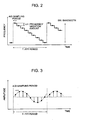
- a principle of the dual-frequency CW method will be described with reference to Figs. 18A to 18C .
- two frequencies f1 and f2 are transmitted while they are switched alternately, as shown in Fig. 18A .
- a frequency for switching periodically the frequencies f1 and f2 is about 100 Hz, and a difference f dev between the two frequencies f1 and f2 is about 300 kHz.
- reception signals at the respective transmission frequencies f1, f2 are subject to a fast Fourier transformation (FFT) processing to obtain frequency spectra of reception beat signals.
- Fig. 18B shows an example of a reception frequency spectrum.
- a signal (target information) as shown in Fig. 18B emerges at a frequency (Doppler frequency) corresponding to a relative speed of the target on the frequency spectrum, when the target emerges.
- target information can be obtained from the two transmission frequencies f1, f2. It is therefore possible to separate and detect a plurality of targets each having a different relative speed from the foregoing obtained information of the frequency spectra, and a relative speed "Rate" for each of the separated and detected targets is calculated from the Doppler frequency ft by using the following expression (1).
- Rate ft ⁇ c 2 ⁇ fc where fc is a transmission frequency, and c is the velocity of light.
- Fig. 18C shows a vector representation of a phase and amplitude in frequency spectrum information at two reception signals in the dual-frequency CW method.
- a phase angle difference ⁇ between two power spectrums F1, F2 is proportional to a distance as far as the target.
- Range c ⁇ ⁇ 4 ⁇ ⁇ ⁇ f dev
- f dev f2 - f1
- ⁇ arg(Signal (1)) - arg(Signal (2))
- c the velocity of light
- the radar using the dual-frequency CW method calculates the relative speed of the target in accordance with the Doppler frequency to then calculate the distance as far as the target in accordance with the phase angle.
- Japanese Patent No. 3746235 relates to a distance measuring apparatus which utilizes a Doppler shift of a reflected wave from a target under measurement to separate a plurality of targets and to detect each of the targets.
- the foregoing distance measuring apparatus radiates a radio wave, receives a reflected wave from the target, and detects the target, in which the apparatus includes: a transmitting unit that transmits continuously a first frequency signal for a predetermined time period or more, transmits continuously a second frequency signal having a predetermined frequency difference from the first frequency, and transmits a signal having a frequency difference of an integer multiple equal to or greater than twice the predetermined frequency difference from the first frequency over signals at N frequencies, where N is an integer equal to or greater than one; a receiving unit that measures a Doppler frequency of the reflected wave from the target at each of the respective transmission frequencies of the first frequency signal, second frequency signal, and N frequency signals; and a detection processing unit that separates the plurality of targets to then detect each of the targets.
- the Doppler frequency is tuned into zero to cause a target not to be detected, in a condition where the distance between the radar and target is not changed in time, that is, the relative speed is zero.
- US 2003/179128 A shows a method and device for determining separation and relative speed of a distant object including sending electromagnetic signals from the observation point, with a frequency shift over a modulation range, in the form of signal segments during a measuring interval, with a frequency separation from each other which are transmitted alternately and the echo signals from which are detected after reflecting from the object.
- the phase difference of the echo signals arising from each signal segment is detected occurring with short reaction time and high precision whereby the signal segments are transmitted with a stepwise shift each time by a frequency step over the modulation range and at least one sampled value for determination of the phase difference for each signal segment is taken.
- US 6,023,238 A describes a method and device for the removal of ambiguity in distance, applied especially to frequency-shift keying continuous-wave radars, wherein the method computes the distance of the targets detected by the radar using several estimation functions.
- the estimation functions give substantially the same result, the targets are defined as being in the field of non-ambiguous distances and when the estimation functions give different results, the targets are defined as being in the domain of ambiguous distances.
- an object of the invention is to provide a distance measuring apparatus including a transmission antenna to radiate a transmission radio wave; a reception antenna to receive a reflected signal from a target; an analog-to-digital (A/D) converter to perform an analog-to-digital conversion for converting a reception signal; and/or a signal processing unit to process the converted signal and to detect the target, in which a transmission frequency of the transmission radio wave to be radiated is switched at a timing synchronized with a sampling frequency of the analog-to-digital conversion.
- A/D analog-to-digital
- the transmission frequency is transmitted continuously at a sampling period of the analog-to-digital conversion (as an inverse number of the sampling frequency).
- the distance measuring apparatus further includes a switching function in the signal processing unit that switches the transmission frequencies in accordance with a predetermined arbitrary pattern
- the switching function uses a Fourier transformation processing to be executed for a predetermined period to switch the transmission frequency in accordance with the arbitrary pattern as a single unit of the predetermined period of executing the Fourier transformation processing.
- the arbitrary pattern includes a pattern of a butterfly computation to be used for the fat Fourier transformation.
- the arbitrary pattern is stored in advance, and the Fourier transformation processing is executed after decoding the reception signals in accordance with the arbitrary pattern stored at the reception.
- the arbitrary pattern includes a pattern in accordance with a pseudo random code.
- the arbitrary pattern includes a pattern, frequencies of which are switched stepwise, while a predetermined frequency difference is kept constant.
- a difference between a previously transmitted frequency and a presently transmitted frequency is restricted equal to or less than the predetermined frequency difference, when the transmission frequency is switched.
- the distance measuring apparatus further includes a gate function to switch whether the reception signal is passed through on the reception, wherein the received signal is prohibited to pass through for a predetermined time period from a time when the transmission frequency is switched.
- the predetermined time period is a time until an oscillator for generating the transmission signal is made stable after the transmission frequency varies.
- an input voltage-to-frequency characteristic (V - f characteristic) of a voltage controlled oscillator for generating the transmission signal is stored in advance, a necessary voltage for generating a predetermined frequency is calculated from the input voltage-to-frequency characteristic, or a necessary voltage for transmitting the predetermined frequency is calculated by a method of referring to a table.
- the invention it is possible to detect a target even in a condition where the relative speed is zero, and it is also possible to detect a distance in high accuracy by separating plural targets which emerge on the same speed.
- Fig. 1 is a block diagram showing a radar apparatus in the invention.
- a transmitter 18 generates a transmission signal with a transmission frequency on the basis of a modulation signal from a modulator 17, and a high frequency signal generated from the transmitter is radiated from a transmission antenna 10.
- the distance measuring apparatus for use in the automobiles uses a signal of a millimeter-wave of 76 GHz or 24 GHz band, or a sub-millimeter-wave band.
- a radio signal reflected from a target (object under measurement) such as vehicles, obstacles, etc. is received from a reception antenna 11 to then give a frequency conversion by a mixer 12.
- Part of the output signal from the transmitter 18 is supplied to the mixer 12 through a directional coupler, and the signal from the transmitter 18 is mixed with the reception signal from the reception antenna 11 by the mixer 12 to generate a beat signal.
- the beat signal outputted from the mixer 12 has a Doppler frequency.
- the beat signal, outputted from the mixer 12 is then supplied to an analog-to-digital (A/D) converter 14 from an analog circuit unit 13 to convert into a digital signal, and to then supply to a FFT (Fast Fourier Transformation) processing unit 2.
- the FFT processing unit 2 processes a series of analog-to-digital converted data by a complex number Fourier transformation processing, so that frequency spectra of the beat signals are measured as amplitude information and phase information.
- Fig. 2 shows an example of a frequency pattern of a transmission signal supplied from the foregoing distance measuring apparatus in a first embodiment.
- the frequency pattern is synchronized with an analog-to-digital sampling period, and uses a transmission wave, the frequency of which is decreased stepwise within a FFT period.
- the modulator 17 shown in Fig. 1 generates a voltage for controlling the transmitter 18 on the basis of a command value supplied from an arbitrary pattern generation processing unit 4 to then send to the transmitter 18.
- the transmitter 18 generates a predetermined frequency which is decreased with a variation amount ⁇ f stepwise, as shown in Fig. 2 , to radiate it from the transmission antenna 10. Thereafter, A signal reflected from the target is received by the reception antenna 11, and converted into a low frequency beat signal by the mixer 12.
- a transmission signal Sn t (t) is represented by the following expression (3).
- S ⁇ n t t At ⁇ exp j ⁇ 2 ⁇ ⁇ ⁇ fn ⁇ t + ⁇ n
- At is an amplitude of the transmission signal
- fn is a transmission frequency
- ⁇ n is an initial phase.
- the reception signal is represented by the following expressions (4) and (5).
- S ⁇ n r t Ar ⁇ exp j 2 ⁇ ⁇ ⁇ fn ⁇ t - ⁇ t + ⁇ n
- Ar is an amplitude of the reception signal
- ⁇ is a delay time due to the distance.
- ⁇ t 2 ⁇ Range t c
- the beat signal supplied from the mixer 12 is represented by the following expression (6).
- the transmission frequency is synchronized with the analog-to-digital sampling period, and the transmission signal varying stepwise is represented by the following expression (7).
- fn f ⁇ 0 - n ⁇ ⁇ ⁇ f T ⁇ t
- f0 an initial value of the transmission frequency
- n an integer which is counted up from 0 to total number of samples in the FFT period.
- ⁇ f is a variation amount of the frequency.
- the reception beat signal is represented by the following expression (8).
- S ⁇ n IF t A IF ⁇ exp j 2 ⁇ ⁇ ⁇ f ⁇ 0 - n ⁇ ⁇ ⁇ f T ⁇ t ⁇ ⁇ t
- Fig. 3 shows an example of the reception beat signal which is sampled in the analog-to-digital sampling period.
- This waveform is a sinusoidal wave determined by a distance as far as the target and its relative speed, and steps in accordance with the transmission frequency which is varied stepwise.
- the sinusoidal wave formed of connecting measured data at each of the steps is obtained as shown in Fig. 3 , since the transmission is performed while the transmission frequency is varied stepwise.
- a frequency peak signal emerges in response to the distance as far as the target, as shown in Fig. 4 .
- Fig. 4 shows an example of the reception beat signal which is sampled in the analog-to-digital sampling period.
- a reflected signal from the target is emerged at a point of a frequency fp, and this frequency fp becomes a function determined by the distance as far as the target and its relative speed, and steps in accordance with the transmission frequency which is varied stepwise.
- Range c 2 ⁇ T n ⁇ ⁇ ⁇ f ⁇ fp
- the transmitter 18 has its inherent input voltage-to-frequency characteristic (V - f characteristic) as shown in Fig. 5 .
- This V - f characteristic is stored in a storage unit 19 in advance.
- a necessary control voltage for generating a predetermined frequency is then obtained by using the stored V - f characteristic, or the control voltage is supplied to the transmitter 18 with reference to a table. In this way, the predetermined transmission frequency can be transmitted regardless of the characteristic of the transmitter 18.
- a frequency is set so that the transmission frequency is varied from f o to f n in even intervals stepwise.
- voltages V o to V n necessary for transmitting the frequencies from f o to f n are measured and stored in a storage unit 19 in advance.
- the arbitrary pattern generation processing unit 4 in a signal processing unit 1 sets the control voltage to be supplied to the transmitter 18 through the modulator 17 on the basis of information of the voltages V o to V n stored in the storage unit 19 in advance. In this way, a modulation signal is supplied to the transmitter 18, so that the transmission frequencies can be transmitted while the frequency variation amount ⁇ f is kept constant, and the transmission frequencies are switched.
- a second embodiment will be described with reference to Fig. 6 and Fig. 7 .
- the first embodiment has used the transmission frequencies that are varied stepwise, as shown in Fig. 2 .
- the transmission frequencies are varied by synchronization with the analog-to-digital sampling period as shown in Fig. 6 , however, its transmission frequency pattern uses a transmission frequency of an arbitrary random pattern in the FFT period.
- Received signals are converted into digital signals by the analog-to-digital converter 14, after that, the order of sampling signals are rearranged by a rearrangement processing unit 3.
- the rearrangement processing unit 3 rearranges the analog-to-digital converted data in order similar to the case where the frequencies on transmission are varied stepwise, since the pattern on transmission is known.
- the rearranged data in the order is subject to the FFT processing in the FFT processing unit 2, so that the same processing as that in the first embodiment can be made.
- An arbitrary pattern of the transmission frequencies shown in the upper part of Fig. 6 uses specifically a pseudo random code such as M-sequence code, Gold-sequence code, etc. Further, the arbitrary pattern is stored in the storage unit 19 in advance. In the case where some sort of interfacial wave emerges on a midstream of the sequential transmission frequencies by causing the use of such pseudo random code, there is a merit to be able to make affection small on the interfacial wave.
- a radio wave is transmitted by using the arbitrary pattern.
- a signal reflected from a target is received to convert into digital data by the analog-to-digital converter 14.
- the analog-to-digital converted sampling data equal to or greater than the number of samples is stored for undergoing the FFT processing, and the analog-to-digital converted sampling data received by using the arbitrary pattern on the transmission is rearranged in order (referring to the lower part of Fig. 6 ) at a step 102.
- the sequential data is subject to the FFT processing.
- a peak signal reflected from the target obtained from a result of the FFT processing is measured to calculate a distance as far as the target and its relative speed from information containing a frequency, amplitude and phase of the peak signal.
- a third embodiment is concerned with a case where two series pieces of data in which transmission frequencies are varied stepwise is subject to the FFT processing.
- Figs. 8A and 8B show transmission frequency patterns to be used for the FFT processing.
- Fig. 8A shows, similarly to Fig. 2 , transmission frequencies to be used for a method in which the frequencies to be transmitted are varied stepwise by synchronization with the analog-to-digital sampling period, that is, shows data of an amount of two FFT periods (T1, T2).
- the distance as far as the target does not vary.
- a frequency of a peak signal reflected from the target becomes one synthesized with components of the distance and relative speed.
- a peak signal frequency fp 2 ⁇ Rate c ⁇ fc + n ⁇ ⁇ ⁇ f T ⁇ 2 ⁇ Range c
- a difference ⁇ fp between a frequency fp1 of the peak signal at a time T1 and a frequency fp2 of the peak signal at a time T2 is represented by the following expression (11).
- ⁇ ⁇ fp fp ⁇ 2 - fp ⁇ 1
- Range 2 - Range 1 Rate ⁇ T
- ⁇ fp is also represented by the following expression (13).
- the relative speed "Rate” is obtained from the following expression (14) by using the frequency difference ⁇ fp from the time T1 to T2.
- Rate c 2 ⁇ n ⁇ ⁇ ⁇ f ⁇ ⁇ ⁇ fp
- the distance as far as the target and its relative speed can be obtained by using the result of two series of FFT processing.
- a fourth embodiment will be described with use of Fig. 9 and Fig. 10 .
- the frequency fp of the peak signal reflected from the target contains a Doppler frequency in accordance with the variation (relative speed) of distance.
- the principle of dual-frequency CW method is utilized in this case so that a component (relative speed) and the distance of the Doppler frequency are separated and measured each other.
- upper-side frequencies and lower-side frequencies both of which are separated by a minute frequency difference f dev , are transmitted as a transmission signal.
- the respective frequencies are varied stepwise by the frequency variation amount ⁇ f, as similarly shown in Fig. 2 .
- the analog-to-digital sample period is made twice and high-speed, and data of the two frequencies or the upper-side and lower-side frequencies can be obtained from a single interval of the FFT period. These pieces of data are separated into the upper-side frequencies and lower-side frequencies to rearrange these data, so that two data strings, the transmission frequencies of which are varied stepwise, can be obtained as shown in the lower part of Fig. 9 .
- the analog-to-digital converted data string in this case is shown in Fig. 10 .
- these pieces of the analog-to-digital converted data are separated into and connected the upper-side frequencies with lower-side frequencies. These two reception signals are observed as two signals each having the same frequency, but having a different phase.
- the FFT processing is applied to the two reception signals or the upper-side and lower-side frequencies, so that spectrum information shown in Fig. 11A can be obtained.
- the reflected signal from the target is then emerged as a peak signal on the spectrum information.
- a frequency emerging the peak signal is one synthesized with the distance and relative speed as indicated by the expression (10).
- a difference between a phase angle of the peak signal obtained from the spectrum information of the upper-side frequency and a phase angle of the peak signal of the lower-side frequency is indicated by Fig. 11B .
- the distance "Range” is calculated by the same calculation method as the dual-frequency CW method, as indicated by the expression (2), since these pieces of phase angle information become the same power spectrum information as the dual-frequency CW method.
- a value of the relative speed "Rate” can be obtained from the calculated distance information "Range” and the frequency fp of the measured peak signal by using the expression (10).
- a difference between the upper-side and lower-side frequencies is about 300 KHz in the case of a long-range radar to be used for controlling a distance between the automobiles.
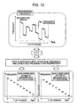
- Fig. 12 it is identical to the example in Fig. 9 that the transmission signal is transmitted as a set of the two frequencies corresponding to the upper-side and lower-side frequencies.
- the method in the fifth embodiment is that the set of the frequencies is transmitted while they are modulated by an arbitrary pattern on the basis of the FFT period.
- Received signals are converted into digital signals by the analog-to-digital converter 14, and the upper-side and lower-side frequencies are then separated and rearranged.
- the received analog-to-digital converted data is rearranged in order similar to the variation such that the upper-side and lower-side frequencies as frequencies on transmission are varied stepwise.
- Fig. 12 shows a data concept which is rearranged stepwise. After the rearrangement as describe above, the processing which utilizes the principle of dual-frequency CW method similar to that described with Fig. 11 is applied to the data, so that the distance as far as the target and its relative speed can be calculated.
- a sixth embodiment will be described with use of Fig. 13 and Fig. 14 .
- a method to be described in this case uses a radar measurement principle of FMCW (Frequency Modulation Continuous Wave) method.
- FMCW Frequency Modulation Continuous Wave
- the transmission frequencies are varied by synchronization with the analog-to-digital sampling period, but its transmission frequency pattern is set to an arbitrary pattern on the basis of the FFT period. The arbitrary pattern is therefore transmitted over two FFT periods.
- Fig. 13 shows an example indicating that arbitrary patterns of frequencies to be transmitted are varied for a first FFT period and second FFT period.
- received signals are converted into digital signals by the analog-to-digital converter 14, after that, sampling signals are rearranged in order by the rearrangement processing unit 3.
- the rearrangement processing unit 3 rearranges the received analog-to-digital converted data in order similar to the variation such that the frequencies on transmission are varied stepwise, since the arbitrary pattern on transmission is known.
- the data is rearranged such that the frequency variation is descended stepwise for the first FFT period, and ascended stepwise for the second FFT period.
- the rearranged series data is supplied to the FFT processing unit 2 to undergo the FFT processing.
- a result of the FFT processing is shown in Fig. 14 as a spectrum waveform, that is, the results for a descending period and ascending period.
- the FFT processing is often utilized as a fast algorism to convert time domain data into frequency domain data.
- the data in the time domain can be outputted in order by rearranging the time domain data in advance and by repeating a butterfly computation.
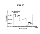
- the frequencies to be transmitted are varied by synchronization with the analog-to-digital sampling period, and its transmission frequency pattern is set to a certain arbitrary pattern based on the FFT period.
- a method indicates that the FFT period is separated more, and a band in which the frequency is varied in a separated time period is restricted. An amount of transiting the frequencies in a certain time period is restricted to shorten the transition time period from one to another frequency, so that a frequency stability after the transition can be enhanced.
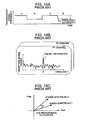
- FIG. 17A shows an example of the analog circuit unit 13 containing an amplifier 31, a reception gate 30, and a sample-hold circuit 32.
- the transmission frequency is made varied stepwise, there is a tendency for an overshoot to arise from an actual transmission frequency dependent on a characteristic of the transmitter 18, in response to a command value of the transmission frequency as shown in Fig. 17B .
- the reception gate 30 is incorporated into the analog circuit unit 13.
- the command value of the transmission frequency is transited, and the reception gate 30 is then turned On after elapsed by a predetermined time width ⁇ t. Further, the reception gate 30 is turned Off at a time little before commanding the transition of a next frequency.
- a signal in a time period during which the reception gate 30 is turned On is held by the sample-hold circuit 32 to then convert into digital data by the analog-to-digital converter 14.
- the function of reception gate 30 is added to the analog circuit unit 13, so that the adverse effect of a.frequency hunting so-called the overshoot and undershoot of the transmission frequency by causing the switching of the command value in the transmission frequency can be eliminated, enabling measurement in high accuracy.
- the radar apparatus as described above can be used for a distance measuring apparatus to measure a distance from a vehicle or automobile in front of own one.
- the radar apparatus can also be used for a carmounted radar device to measure a position, a direction, and a relative speed in relation to various targets which are found in front, side and rear directions. Further it is possible to widely use the radar apparatus such as a ground radar to measure a traffic and monitor a specific spot.
Claims (6)
- Entfernungsmessvorrichtung mit einer Sendeantenne (10) zum Ausstrahlen einer Sendefunkwelle; einer Empfangsantenne (11) zum Empfangen eines reflektierten Signals von einem Ziel; einem Mischer (12) zum Kombinieren des reflektierten Signals mit einem Bereich des gesendeten Signals zur Bereitstellung eines Empfangsschwebungssignals; einem Analog/Digital-Wandler (14) zur Durchführung einer Analog/Digital-Umwandlung zum Umwandeln des Empfangsschwebungssignals; und einer Signalverarbeitungseinheit (1) zum Verarbeiten des umgewandelten Signals und zum Erfassen des Ziels unter Verwendung einer Fouriertransformationsverarbeitung (FFT),
wobei eine Sendefrequenz der auszustrahlenden Sendefunkwelle, die innerhalb einer FFT-Spanne schrittweise abnimmt, bei einer Zeiteinstellung umgeschaltet wird, die mit einer Abtastfrequenz der Analog/Digital-Umwandlung synchronisiert ist,
dadurch gekennzeichnet, dass die zu sendenden Frequenzen nach Maßgabe eines vorgegebenen willkürlichen Musters neu angeordnet werden, damit das Empfangsschwebungssignal bei einer schnellen Fourierverarbeitung angewendet wird, die mehrere Schmetterlingsberechnungen umfasst, ohne die Reihenfolge neu zu ordnen, so dass auf eine Neuordnung von FFT-Ausgangsdaten verzichtet wird. - Entfernungsmessvorrichtung nach Anspruch 1, wobei die Sendefrequenz bei einer Abtastspanne der Analog/Digital-Umwandlung (als Kehrwert der Abtastfrequenz) kontinuierlich gesendet wird.
- Entfernungsmessvorrichtung nach mindestens einem der Ansprüche 1 oder 2, wobei eine Differenz zwischen einer zuvor gesendeten Frequenz und einer aktuell gesendeten Frequenz beschränkt gleich oder weniger als die vorgegebene Frequenzdifferenz ist, wenn die Sendefrequenz umgeschaltet wird.
- Entfernungsmessvorrichtung nach mindestens einem der Ansprüche 1 bis 3, ferner mit einer Gate-Funktion (30) zum Umschalten, ob das Empfangssignal durch den Empfang hindurchgeht, wobei eine vorgegebene Zeitspanne lang ab einer Zeit, wenn die Sendefrequenz umgeschaltet wird, verhindert wird, dass das empfangene Signal hindurchgeht.
- Entfernungsmessvorrichtung nach Anspruch 4, wobei die vorgegebene Zeitspanne eine Zeit ist, bis ein Oszillator (18) nach dem Variieren der Sendefrequenz zum Erzeugen des Sendesignals stabil gemacht worden ist.
- Entfernungsmessvorrichtung nach mindestens einem der Ansprüche 1 bis 5, wobei eine eingegebene Spannung-zu-Frequenz-Kennlinie (V-f-Kennlinie) eines spannungsgesteuerten Oszillators (18) zum Erzeugen des Sendesignals vorab gespeichert wird, eine notwendige Spannung zum Erzeugen einer vorgegebenen Frequenz aus der eingegebenen Spannung-zu-Frequenz-Kennlinie berechnet wird oder eine notwendige Spannung zum Senden der vorgegebenen Frequenz durch ein Verfahren der Bezugnahme auf eine Tabelle berechnet wird.
Applications Claiming Priority (1)
| Application Number | Priority Date | Filing Date | Title |
|---|---|---|---|
| JP2007207092A JP4724694B2 (ja) | 2007-08-08 | 2007-08-08 | 電波レーダ装置 |
Publications (2)
| Publication Number | Publication Date |
|---|---|
| EP2026098A1 EP2026098A1 (de) | 2009-02-18 |
| EP2026098B1 true EP2026098B1 (de) | 2012-12-26 |
Family
ID=39926744
Family Applications (1)
| Application Number | Title | Priority Date | Filing Date |
|---|---|---|---|
| EP08013679A Expired - Fee Related EP2026098B1 (de) | 2007-08-08 | 2008-07-30 | Radarvorrichtung |
Country Status (3)
| Country | Link |
|---|---|
| US (1) | US8232914B2 (de) |
| EP (1) | EP2026098B1 (de) |
| JP (1) | JP4724694B2 (de) |
Families Citing this family (32)
| Publication number | Priority date | Publication date | Assignee | Title |
|---|---|---|---|---|
| CN102119340B (zh) * | 2008-03-19 | 2014-10-22 | 阿维·佐哈尔 | 用于对物品和场所进行定位的系统和方法 |
| JP2010048635A (ja) * | 2008-08-21 | 2010-03-04 | Hitachi Ltd | レーダ装置 |
| JP5704552B2 (ja) * | 2009-03-03 | 2015-04-22 | 国立大学法人電気通信大学 | レーダ装置 |
| GB2472623A (en) * | 2009-08-12 | 2011-02-16 | Thales Holdings Uk Plc | Continuous wave radar with frequency shift keying |
| JP5707037B2 (ja) * | 2009-12-25 | 2015-04-22 | 日本電産エレシス株式会社 | 電子走査型レーダ装置、受信波方向推定方法及び受信波方向推定プログラム |
| DE102010006334A1 (de) * | 2010-01-29 | 2011-08-04 | pro-micron GmbH & Co. KG, 87600 | System und Verfahren zur Störunterdrückung bei frequenzmodulierten Radarsystemen |
| JP5695830B2 (ja) * | 2010-02-08 | 2015-04-08 | 日本電産エレシス株式会社 | 電子走査型レーダ装置、受信波方向推定方法及び受信波方向推定プログラム |
| DK2372667T3 (da) * | 2010-04-02 | 2012-12-10 | Kapsch Trafficcom Ag | Fremgangsmåde til detektering af køretøjer med anhængere |
| JP5647814B2 (ja) * | 2010-05-19 | 2015-01-07 | 日本電産エレシス株式会社 | 電子走査型レーダ装置、受信波方向推定方法及び受信波方向推定プログラム |
| US9140783B2 (en) | 2010-06-17 | 2015-09-22 | Mitsubishi Electric Corporation | Radar device |
| JP5633848B2 (ja) * | 2010-10-19 | 2014-12-03 | 公益財団法人北九州産業学術推進機構 | 超広帯域パルス・センサ及びその干渉回避方法 |
| JP5732706B2 (ja) * | 2010-10-19 | 2015-06-10 | 公益財団法人北九州産業学術推進機構 | 超広帯域パルス・センサ |
| US8207888B1 (en) * | 2011-01-24 | 2012-06-26 | The United States Of America As Represented By The Secretary Of The Navy | Systems and methods of range tracking |
| US9733345B2 (en) | 2011-07-13 | 2017-08-15 | Iseeloc, Inc. | System and method for enhanced point-to-point direction finding |
| DE102013210256A1 (de) | 2013-06-03 | 2014-12-04 | Robert Bosch Gmbh | Interferenzunterdrückung bei einem fmcw-radar |
| US9395229B2 (en) | 2014-03-05 | 2016-07-19 | Rosemount Tank Radar Ab | Low power radar level gauge system with integrated microwave circuit |
| US9389113B2 (en) | 2014-03-05 | 2016-07-12 | Rosemount Tank Radar Ab | Low power radar level gauge system |
| JP2015184200A (ja) * | 2014-03-25 | 2015-10-22 | 横河電子機器株式会社 | レーダ装置 |
| CN103995261B (zh) * | 2014-05-23 | 2017-09-26 | 广东电网公司电力科学研究院 | 无人机避障系统的目标信号处理装置、无人机避障系统 |
| JP6552167B2 (ja) * | 2014-07-16 | 2019-07-31 | 株式会社デンソー | 車載レーダ装置および報知システム |
| CN104101874A (zh) * | 2014-07-25 | 2014-10-15 | 绵阳彬华科技有限公司 | 一种基于雷达技术的距离偏测系统 |
| DE102014010990B4 (de) * | 2014-07-29 | 2021-06-17 | Jenoptik Robot Gmbh | Verfahren und Vorrichtung zum Erkennen von einer Geschwindigkeit und einer Entfernung zumindest eines Objekts in Bezug zu einem Empfänger eines Empfangssignals |
| JP6406601B2 (ja) * | 2014-08-05 | 2018-10-17 | パナソニックIpマネジメント株式会社 | レーダ装置および物体検知方法 |
| JP6755876B2 (ja) * | 2015-02-16 | 2020-09-16 | 華為技術有限公司Huawei Technologies Co.,Ltd. | 測距方法及び装置 |
| US9977116B2 (en) * | 2015-10-05 | 2018-05-22 | Analog Devices, Inc. | Scaling fixed-point fast Fourier transforms in radar and sonar applications |
| WO2017064835A1 (ja) | 2015-10-16 | 2017-04-20 | 日本電気株式会社 | ターゲット情報検出システム及びターゲット情報検出方法 |
| JP6560165B2 (ja) * | 2016-07-08 | 2019-08-14 | 株式会社Soken | レーダ装置 |
| US11061103B1 (en) | 2017-02-10 | 2021-07-13 | Iseeloc, Inc. | Navigation system, device and method using unsynchronized nodes |
| JP7111455B2 (ja) * | 2017-09-29 | 2022-08-02 | 株式会社デンソーテン | レーダ装置およびレーダ装置の制御方法 |
| JP6640269B2 (ja) * | 2018-04-19 | 2020-02-05 | 京セラ株式会社 | 電子機器、電子機器の制御方法、及び電子機器の制御プログラム |
| CN113805166A (zh) * | 2021-08-17 | 2021-12-17 | 浙江中控技术股份有限公司 | 一种雷达物位计的目标跟踪测距方法及系统 |
| WO2024005803A1 (en) * | 2022-06-29 | 2024-01-04 | Intel Corporation | Radar apparatus, system, and method |
Family Cites Families (43)
| Publication number | Priority date | Publication date | Assignee | Title |
|---|---|---|---|---|
| US3662388A (en) * | 1970-07-27 | 1972-05-09 | Us Navy | Method and apparatus for recording high range resolution radar data |
| US4015260A (en) * | 1970-11-02 | 1977-03-29 | Raytheon Company | Digital MTI radar |
| US3879661A (en) * | 1972-02-01 | 1975-04-22 | Raytheon Co | Signal processor and subassemblies therefor |
| US3940766A (en) * | 1973-04-05 | 1976-02-24 | The United States Of America As Represented By The Secretary Of The Navy | Range and angle discriminator for leading edge radar tracking |
| US3950750A (en) * | 1974-10-03 | 1976-04-13 | Raytheon Company | Radar system having quadrature phase detector compensator |
| US4003052A (en) * | 1975-12-15 | 1977-01-11 | United Technologies Corporation | Digital prefilter for clutter attenuation in MTI radars |
| US4268828A (en) * | 1979-09-19 | 1981-05-19 | Ford Aerospace & Communications Corporation | Swept frequency radar system employing phaseless averaging |
| US4404562A (en) * | 1980-08-25 | 1983-09-13 | The United States Of America As Represented By The Secretary Of The Navy | Low sidelobe linear FM chirp system |
| US4450444A (en) * | 1981-05-29 | 1984-05-22 | The United States Of America As Represented By The Secretary Of The Navy | Stepped frequency radar target imaging |
| US4652882A (en) * | 1982-09-30 | 1987-03-24 | Raytheon Company | Receiver with wide dynamic range |
| DE3376688D1 (en) * | 1982-11-16 | 1988-06-23 | Hollandse Signaalapparaten Bv | Pulse radar apparatus |
| US4768035A (en) * | 1985-04-18 | 1988-08-30 | The Johns Hopkins University | Coherent radar digital data collector and sampling technique for noncoherent transmitter radars |
| US4710772A (en) * | 1985-12-05 | 1987-12-01 | Raytheon Company | Log magnitude pulse interference detection for a radar system |
| US4680588A (en) * | 1985-12-05 | 1987-07-14 | Raytheon Company | Radar system with incremental automatic gain control |
| US4713662A (en) * | 1986-10-17 | 1987-12-15 | Westinghouse Electric Corp. | Modulated digital radio frequency memory |
| WO1992019980A2 (en) | 1991-05-06 | 1992-11-12 | Ivhs Technologies, Inc. | Multi-frequency automotive radar system |
| JPH05126943A (ja) * | 1991-11-01 | 1993-05-25 | Toshiba Corp | 高分解能レーダ装置 |
| US6448926B1 (en) * | 1993-11-19 | 2002-09-10 | Itt Manufacturing Enterprises, Inc. | Multi-band, multi-function integrated transceiver |
| US5623928A (en) * | 1994-08-05 | 1997-04-29 | Acuson Corporation | Method and apparatus for coherent image formation |
| US5610613A (en) * | 1995-09-15 | 1997-03-11 | Raytheon Company | Analog to digital conversion system |
| DE19781709T1 (de) * | 1996-04-16 | 1999-05-27 | William M Sunlin | Materialdurchdringendes Bildradar |
| US5999119A (en) * | 1996-12-18 | 1999-12-07 | Raytheon Company | CW radar range measuring system with improved range resolution |
| US5923280A (en) * | 1997-01-17 | 1999-07-13 | Automotive Systems Laboratory, Inc. | Vehicle collision radar with randomized FSK wave form |
| FR2761480B1 (fr) * | 1997-03-28 | 1999-06-11 | Thomson Csf | Procede et dispositif de levee d'ambiguite en distance appliquee notamment a un radar a onde continue et a saut de frequence |
| US5999561A (en) * | 1997-05-20 | 1999-12-07 | Sanconix, Inc. | Direct sequence spread spectrum method, computer-based product, apparatus and system tolerant to frequency reference offset |
| US5867119A (en) * | 1997-10-02 | 1999-02-02 | Mcdonnell Douglas Corporation | Precision height measuring device |
| JP3525425B2 (ja) * | 1997-10-31 | 2004-05-10 | トヨタ自動車株式会社 | Fm−cwレーダ |
| US6204805B1 (en) * | 1998-02-06 | 2001-03-20 | Honeywell Inc. | Dual target tracking altimeter |
| US5986602A (en) * | 1998-03-02 | 1999-11-16 | Remote Data Systems, Inc. | Pulse radar device and method |
| US6081226A (en) * | 1998-07-10 | 2000-06-27 | Northrop Grumman Corporation | Multi-mode radar exciter |
| JP3746235B2 (ja) | 2000-01-28 | 2006-02-15 | 株式会社日立製作所 | 距離計測装置 |
| US6317074B1 (en) * | 2000-06-15 | 2001-11-13 | Alliant Techsystems Inc. | High range resolution radar through non-uniform sampling |
| JP4111667B2 (ja) * | 2000-09-26 | 2008-07-02 | 富士通テン株式会社 | Fm−cwレーダ装置 |
| JP2002107447A (ja) * | 2000-10-03 | 2002-04-10 | Mitsubishi Electric Corp | レーダ装置 |
| DE10050278B4 (de) * | 2000-10-10 | 2005-06-02 | S.M.S., Smart Microwave Sensors Gmbh | Verfahren und Vorrichtung zur Bestimmung von Abstand und Relativgeschwindigkeit eines entfernten Objektes |
| JP2002156447A (ja) * | 2000-11-20 | 2002-05-31 | Wire Device:Kk | スイープ発振装置及びfmcw距離計測装置 |
| JP3703014B2 (ja) * | 2001-05-11 | 2005-10-05 | 三菱電機株式会社 | レーダ信号処理装置、及び距離・速度計測方法 |
| GB2401269A (en) * | 2003-04-30 | 2004-11-03 | Secr Defence | Digital electronic support measures |
| DE10349919A1 (de) * | 2003-10-25 | 2005-05-25 | Volkswagen Ag | Messgerät für ein Kraftfahrzeug |
| US20050156780A1 (en) * | 2004-01-16 | 2005-07-21 | Ghz Tr Corporation | Methods and apparatus for automotive radar sensors |
| JP4420743B2 (ja) * | 2004-05-31 | 2010-02-24 | 富士通テン株式会社 | Fm−cwレーダ装置 |
| US7167124B2 (en) * | 2004-12-23 | 2007-01-23 | Sensors & Software Inc. | Data acquisition for a ground penetrating radar system |
| DE602005014679D1 (de) * | 2005-02-08 | 2009-07-09 | Mitsubishi Electric Corp | Zieldetektionseinrichtung |
-
2007
- 2007-08-08 JP JP2007207092A patent/JP4724694B2/ja active Active
-
2008
- 2008-07-30 EP EP08013679A patent/EP2026098B1/de not_active Expired - Fee Related
- 2008-08-06 US US12/187,093 patent/US8232914B2/en not_active Expired - Fee Related
Also Published As
| Publication number | Publication date |
|---|---|
| US20090085796A1 (en) | 2009-04-02 |
| EP2026098A1 (de) | 2009-02-18 |
| JP2009042061A (ja) | 2009-02-26 |
| JP4724694B2 (ja) | 2011-07-13 |
| US8232914B2 (en) | 2012-07-31 |
Similar Documents
| Publication | Publication Date | Title |
|---|---|---|
| EP2026098B1 (de) | Radarvorrichtung | |
| EP1253441B1 (de) | Entfernungsmessgerät | |
| EP1847848B1 (de) | Zieldetektionseinrichtung | |
| US10436890B2 (en) | Method for finding the position of objects using an FMCW radar | |
| US6859168B2 (en) | Radar apparatus | |
| EP1757953B1 (de) | FM-CW-Radarsystem | |
| US9354304B2 (en) | Method for cyclically measuring distances and velocities of objects using an FMCW radar sensor | |
| US10386472B2 (en) | Radar device signal processing device and signal processing method for radar device | |
| US8866668B2 (en) | Radar apparatus with different operation modes | |
| US6606052B1 (en) | Method and apparatus for detecting multiple objects with frequency modulated continuous wave radar | |
| JP4769684B2 (ja) | 電子走査式レーダ装置 | |
| Rohling et al. | Radar waveform for automotive radar systems and applications | |
| US6646589B2 (en) | Radar designed to minimize error in detecting target | |
| EP1617233B1 (de) | Radargerät und Verfahren zur Steuerung eines Radargeräts | |
| US7466260B2 (en) | Radar apparatus | |
| EP0777133A1 (de) | FM-CW-Radar-Anlage zum Messen der relativen Geschwindigkeit und der Entfernung eines Objekts | |
| WO2016033361A1 (en) | Improving the range resolution in fmcw radars | |
| EP1969392A2 (de) | Zeitduplexvorrichtung und verfahren für radarsensor-frontends | |
| JP2007232385A (ja) | 電子走査式レーダ装置 | |
| CN1890578B (zh) | 机动车的测量装置 | |
| US7312745B2 (en) | Radar | |
| US20120119940A1 (en) | Radar apparatus with multi-receiver channel | |
| EP0941489B1 (de) | Verfahren zur bestimmung der relativen geschwindigkeit zwischen zwei sich bewegenden objekten | |
| CN116194801A (zh) | 低信号处理负荷情况下具有高距离分辨率的雷达方法及雷达系统 | |
| JP2750781B2 (ja) | Fmレーダ |
Legal Events
| Date | Code | Title | Description |
|---|---|---|---|
| PUAI | Public reference made under article 153(3) epc to a published international application that has entered the european phase |
Free format text: ORIGINAL CODE: 0009012 |
|
| 17P | Request for examination filed |
Effective date: 20080730 |
|
| AK | Designated contracting states |
Kind code of ref document: A1 Designated state(s): AT BE BG CH CY CZ DE DK EE ES FI FR GB GR HR HU IE IS IT LI LT LU LV MC MT NL NO PL PT RO SE SI SK TR |
|
| AX | Request for extension of the european patent |
Extension state: AL BA MK RS |
|
| 17Q | First examination report despatched |
Effective date: 20090904 |
|
| AKX | Designation fees paid |
Designated state(s): DE FR GB IT |
|
| RIC1 | Information provided on ipc code assigned before grant |
Ipc: G01S 13/24 20060101ALI20120523BHEP Ipc: G01S 13/34 20060101AFI20120523BHEP Ipc: G01S 7/35 20060101ALI20120523BHEP |
|
| GRAP | Despatch of communication of intention to grant a patent |
Free format text: ORIGINAL CODE: EPIDOSNIGR1 |
|
| GRAS | Grant fee paid |
Free format text: ORIGINAL CODE: EPIDOSNIGR3 |
|
| GRAA | (expected) grant |
Free format text: ORIGINAL CODE: 0009210 |
|
| AK | Designated contracting states |
Kind code of ref document: B1 Designated state(s): DE FR GB IT |
|
| REG | Reference to a national code |
Ref country code: GB Ref legal event code: FG4D |
|
| REG | Reference to a national code |
Ref country code: DE Ref legal event code: R096 Ref document number: 602008021082 Country of ref document: DE Effective date: 20130307 |
|
| PGFP | Annual fee paid to national office [announced via postgrant information from national office to epo] |
Ref country code: FR Payment date: 20130621 Year of fee payment: 6 |
|
| PLBE | No opposition filed within time limit |
Free format text: ORIGINAL CODE: 0009261 |
|
| STAA | Information on the status of an ep patent application or granted ep patent |
Free format text: STATUS: NO OPPOSITION FILED WITHIN TIME LIMIT |
|
| 26N | No opposition filed |
Effective date: 20130927 |
|
| PG25 | Lapsed in a contracting state [announced via postgrant information from national office to epo] |
Ref country code: IT Free format text: LAPSE BECAUSE OF FAILURE TO SUBMIT A TRANSLATION OF THE DESCRIPTION OR TO PAY THE FEE WITHIN THE PRESCRIBED TIME-LIMIT Effective date: 20121226 |
|
| REG | Reference to a national code |
Ref country code: DE Ref legal event code: R097 Ref document number: 602008021082 Country of ref document: DE Effective date: 20130927 |
|
| GBPC | Gb: european patent ceased through non-payment of renewal fee |
Effective date: 20130730 |
|
| PG25 | Lapsed in a contracting state [announced via postgrant information from national office to epo] |
Ref country code: GB Free format text: LAPSE BECAUSE OF NON-PAYMENT OF DUE FEES Effective date: 20130730 |
|
| PGFP | Annual fee paid to national office [announced via postgrant information from national office to epo] |
Ref country code: DE Payment date: 20140724 Year of fee payment: 7 |
|
| REG | Reference to a national code |
Ref country code: FR Ref legal event code: ST Effective date: 20150331 |
|
| PG25 | Lapsed in a contracting state [announced via postgrant information from national office to epo] |
Ref country code: FR Free format text: LAPSE BECAUSE OF NON-PAYMENT OF DUE FEES Effective date: 20140731 |
|
| REG | Reference to a national code |
Ref country code: DE Ref legal event code: R119 Ref document number: 602008021082 Country of ref document: DE |
|
| PG25 | Lapsed in a contracting state [announced via postgrant information from national office to epo] |
Ref country code: DE Free format text: LAPSE BECAUSE OF NON-PAYMENT OF DUE FEES Effective date: 20160202 |