EP2023480A2 - Verdichter und Vorrichtung für eine Motorsteuerung - Google Patents
Verdichter und Vorrichtung für eine Motorsteuerung Download PDFInfo
- Publication number
- EP2023480A2 EP2023480A2 EP20080014147 EP08014147A EP2023480A2 EP 2023480 A2 EP2023480 A2 EP 2023480A2 EP 20080014147 EP20080014147 EP 20080014147 EP 08014147 A EP08014147 A EP 08014147A EP 2023480 A2 EP2023480 A2 EP 2023480A2
- Authority
- EP
- European Patent Office
- Prior art keywords
- motor
- value
- current value
- axis
- specified
- Prior art date
- Legal status (The legal status is an assumption and is not a legal conclusion. Google has not performed a legal analysis and makes no representation as to the accuracy of the status listed.)
- Withdrawn
Links
- 230000000737 periodic effect Effects 0.000 claims abstract description 21
- 239000000284 extract Substances 0.000 claims description 7
- 230000004907 flux Effects 0.000 claims description 7
- 238000000034 method Methods 0.000 description 32
- 238000004088 simulation Methods 0.000 description 26
- 230000009467 reduction Effects 0.000 description 23
- 238000010586 diagram Methods 0.000 description 20
- 230000007423 decrease Effects 0.000 description 17
- 238000006243 chemical reaction Methods 0.000 description 11
- 238000004804 winding Methods 0.000 description 11
- 239000007789 gas Substances 0.000 description 10
- 230000001629 suppression Effects 0.000 description 10
- 230000008859 change Effects 0.000 description 8
- 230000006835 compression Effects 0.000 description 8
- 238000007906 compression Methods 0.000 description 8
- 238000002474 experimental method Methods 0.000 description 7
- 238000007796 conventional method Methods 0.000 description 6
- 230000000694 effects Effects 0.000 description 6
- 238000005259 measurement Methods 0.000 description 6
- 239000003507 refrigerant Substances 0.000 description 6
- 238000004458 analytical method Methods 0.000 description 5
- 230000001360 synchronised effect Effects 0.000 description 4
- 238000012546 transfer Methods 0.000 description 4
- 238000005406 washing Methods 0.000 description 4
- 238000004364 calculation method Methods 0.000 description 3
- 238000009795 derivation Methods 0.000 description 3
- 238000013461 design Methods 0.000 description 3
- 230000008569 process Effects 0.000 description 3
- 238000004422 calculation algorithm Methods 0.000 description 2
- 238000002036 drum drying Methods 0.000 description 2
- 238000001035 drying Methods 0.000 description 2
- 238000005457 optimization Methods 0.000 description 2
- 230000009286 beneficial effect Effects 0.000 description 1
- 238000004519 manufacturing process Methods 0.000 description 1
- 238000012986 modification Methods 0.000 description 1
- 238000012545 processing Methods 0.000 description 1
- 230000004044 response Effects 0.000 description 1
Images




Classifications
-
- H—ELECTRICITY
- H02—GENERATION; CONVERSION OR DISTRIBUTION OF ELECTRIC POWER
- H02P—CONTROL OR REGULATION OF ELECTRIC MOTORS, ELECTRIC GENERATORS OR DYNAMO-ELECTRIC CONVERTERS; CONTROLLING TRANSFORMERS, REACTORS OR CHOKE COILS
- H02P21/00—Arrangements or methods for the control of electric machines by vector control, e.g. by control of field orientation
- H02P21/14—Estimation or adaptation of machine parameters, e.g. flux, current or voltage
-
- F—MECHANICAL ENGINEERING; LIGHTING; HEATING; WEAPONS; BLASTING
- F04—POSITIVE - DISPLACEMENT MACHINES FOR LIQUIDS; PUMPS FOR LIQUIDS OR ELASTIC FLUIDS
- F04B—POSITIVE-DISPLACEMENT MACHINES FOR LIQUIDS; PUMPS
- F04B35/00—Piston pumps specially adapted for elastic fluids and characterised by the driving means to their working members, or by combination with, or adaptation to, specific driving engines or motors, not otherwise provided for
- F04B35/04—Piston pumps specially adapted for elastic fluids and characterised by the driving means to their working members, or by combination with, or adaptation to, specific driving engines or motors, not otherwise provided for the means being electric
-
- F—MECHANICAL ENGINEERING; LIGHTING; HEATING; WEAPONS; BLASTING
- F04—POSITIVE - DISPLACEMENT MACHINES FOR LIQUIDS; PUMPS FOR LIQUIDS OR ELASTIC FLUIDS
- F04B—POSITIVE-DISPLACEMENT MACHINES FOR LIQUIDS; PUMPS
- F04B49/00—Control, e.g. of pump delivery, or pump pressure of, or safety measures for, machines, pumps, or pumping installations, not otherwise provided for, or of interest apart from, groups F04B1/00 - F04B47/00
- F04B49/06—Control using electricity
-
- F—MECHANICAL ENGINEERING; LIGHTING; HEATING; WEAPONS; BLASTING
- F04—POSITIVE - DISPLACEMENT MACHINES FOR LIQUIDS; PUMPS FOR LIQUIDS OR ELASTIC FLUIDS
- F04C—ROTARY-PISTON, OR OSCILLATING-PISTON, POSITIVE-DISPLACEMENT MACHINES FOR LIQUIDS; ROTARY-PISTON, OR OSCILLATING-PISTON, POSITIVE-DISPLACEMENT PUMPS
- F04C28/00—Control of, monitoring of, or safety arrangements for, pumps or pumping installations specially adapted for elastic fluids
- F04C28/08—Control of, monitoring of, or safety arrangements for, pumps or pumping installations specially adapted for elastic fluids characterised by varying the rotational speed
-
- H—ELECTRICITY
- H02—GENERATION; CONVERSION OR DISTRIBUTION OF ELECTRIC POWER
- H02P—CONTROL OR REGULATION OF ELECTRIC MOTORS, ELECTRIC GENERATORS OR DYNAMO-ELECTRIC CONVERTERS; CONTROLLING TRANSFORMERS, REACTORS OR CHOKE COILS
- H02P21/00—Arrangements or methods for the control of electric machines by vector control, e.g. by control of field orientation
- H02P21/05—Arrangements or methods for the control of electric machines by vector control, e.g. by control of field orientation specially adapted for damping motor oscillations, e.g. for reducing hunting
-
- H—ELECTRICITY
- H02—GENERATION; CONVERSION OR DISTRIBUTION OF ELECTRIC POWER
- H02P—CONTROL OR REGULATION OF ELECTRIC MOTORS, ELECTRIC GENERATORS OR DYNAMO-ELECTRIC CONVERTERS; CONTROLLING TRANSFORMERS, REACTORS OR CHOKE COILS
- H02P21/00—Arrangements or methods for the control of electric machines by vector control, e.g. by control of field orientation
- H02P21/24—Vector control not involving the use of rotor position or rotor speed sensors
-
- H—ELECTRICITY
- H02—GENERATION; CONVERSION OR DISTRIBUTION OF ELECTRIC POWER
- H02P—CONTROL OR REGULATION OF ELECTRIC MOTORS, ELECTRIC GENERATORS OR DYNAMO-ELECTRIC CONVERTERS; CONTROLLING TRANSFORMERS, REACTORS OR CHOKE COILS
- H02P21/00—Arrangements or methods for the control of electric machines by vector control, e.g. by control of field orientation
- H02P21/24—Vector control not involving the use of rotor position or rotor speed sensors
- H02P21/26—Rotor flux based control
-
- H—ELECTRICITY
- H02—GENERATION; CONVERSION OR DISTRIBUTION OF ELECTRIC POWER
- H02P—CONTROL OR REGULATION OF ELECTRIC MOTORS, ELECTRIC GENERATORS OR DYNAMO-ELECTRIC CONVERTERS; CONTROLLING TRANSFORMERS, REACTORS OR CHOKE COILS
- H02P27/00—Arrangements or methods for the control of AC motors characterised by the kind of supply voltage
- H02P27/04—Arrangements or methods for the control of AC motors characterised by the kind of supply voltage using variable-frequency supply voltage, e.g. inverter or converter supply voltage
- H02P27/06—Arrangements or methods for the control of AC motors characterised by the kind of supply voltage using variable-frequency supply voltage, e.g. inverter or converter supply voltage using DC to AC converters or inverters
- H02P27/08—Arrangements or methods for the control of AC motors characterised by the kind of supply voltage using variable-frequency supply voltage, e.g. inverter or converter supply voltage using DC to AC converters or inverters with pulse width modulation
-
- F—MECHANICAL ENGINEERING; LIGHTING; HEATING; WEAPONS; BLASTING
- F04—POSITIVE - DISPLACEMENT MACHINES FOR LIQUIDS; PUMPS FOR LIQUIDS OR ELASTIC FLUIDS
- F04B—POSITIVE-DISPLACEMENT MACHINES FOR LIQUIDS; PUMPS
- F04B2203/00—Motor parameters
- F04B2203/02—Motor parameters of rotating electric motors
- F04B2203/0209—Rotational speed
-
- F—MECHANICAL ENGINEERING; LIGHTING; HEATING; WEAPONS; BLASTING
- F04—POSITIVE - DISPLACEMENT MACHINES FOR LIQUIDS; PUMPS FOR LIQUIDS OR ELASTIC FLUIDS
- F04C—ROTARY-PISTON, OR OSCILLATING-PISTON, POSITIVE-DISPLACEMENT MACHINES FOR LIQUIDS; ROTARY-PISTON, OR OSCILLATING-PISTON, POSITIVE-DISPLACEMENT PUMPS
- F04C2240/00—Components
- F04C2240/40—Electric motor
- F04C2240/403—Electric motor with inverter for speed control
-
- F—MECHANICAL ENGINEERING; LIGHTING; HEATING; WEAPONS; BLASTING
- F04—POSITIVE - DISPLACEMENT MACHINES FOR LIQUIDS; PUMPS FOR LIQUIDS OR ELASTIC FLUIDS
- F04C—ROTARY-PISTON, OR OSCILLATING-PISTON, POSITIVE-DISPLACEMENT MACHINES FOR LIQUIDS; ROTARY-PISTON, OR OSCILLATING-PISTON, POSITIVE-DISPLACEMENT PUMPS
- F04C2240/00—Components
- F04C2240/80—Other components
- F04C2240/803—Electric connectors or cables; Fittings therefor
-
- F—MECHANICAL ENGINEERING; LIGHTING; HEATING; WEAPONS; BLASTING
- F04—POSITIVE - DISPLACEMENT MACHINES FOR LIQUIDS; PUMPS FOR LIQUIDS OR ELASTIC FLUIDS
- F04C—ROTARY-PISTON, OR OSCILLATING-PISTON, POSITIVE-DISPLACEMENT MACHINES FOR LIQUIDS; ROTARY-PISTON, OR OSCILLATING-PISTON, POSITIVE-DISPLACEMENT PUMPS
- F04C2240/00—Components
- F04C2240/80—Other components
- F04C2240/81—Sensor, e.g. electronic sensor for control or monitoring
-
- F—MECHANICAL ENGINEERING; LIGHTING; HEATING; WEAPONS; BLASTING
- F04—POSITIVE - DISPLACEMENT MACHINES FOR LIQUIDS; PUMPS FOR LIQUIDS OR ELASTIC FLUIDS
- F04C—ROTARY-PISTON, OR OSCILLATING-PISTON, POSITIVE-DISPLACEMENT MACHINES FOR LIQUIDS; ROTARY-PISTON, OR OSCILLATING-PISTON, POSITIVE-DISPLACEMENT PUMPS
- F04C2270/00—Control; Monitoring or safety arrangements
- F04C2270/01—Load
-
- F—MECHANICAL ENGINEERING; LIGHTING; HEATING; WEAPONS; BLASTING
- F04—POSITIVE - DISPLACEMENT MACHINES FOR LIQUIDS; PUMPS FOR LIQUIDS OR ELASTIC FLUIDS
- F04C—ROTARY-PISTON, OR OSCILLATING-PISTON, POSITIVE-DISPLACEMENT MACHINES FOR LIQUIDS; ROTARY-PISTON, OR OSCILLATING-PISTON, POSITIVE-DISPLACEMENT PUMPS
- F04C2270/00—Control; Monitoring or safety arrangements
- F04C2270/03—Torque
-
- F—MECHANICAL ENGINEERING; LIGHTING; HEATING; WEAPONS; BLASTING
- F04—POSITIVE - DISPLACEMENT MACHINES FOR LIQUIDS; PUMPS FOR LIQUIDS OR ELASTIC FLUIDS
- F04C—ROTARY-PISTON, OR OSCILLATING-PISTON, POSITIVE-DISPLACEMENT MACHINES FOR LIQUIDS; ROTARY-PISTON, OR OSCILLATING-PISTON, POSITIVE-DISPLACEMENT PUMPS
- F04C2270/00—Control; Monitoring or safety arrangements
- F04C2270/05—Speed
-
- F—MECHANICAL ENGINEERING; LIGHTING; HEATING; WEAPONS; BLASTING
- F04—POSITIVE - DISPLACEMENT MACHINES FOR LIQUIDS; PUMPS FOR LIQUIDS OR ELASTIC FLUIDS
- F04C—ROTARY-PISTON, OR OSCILLATING-PISTON, POSITIVE-DISPLACEMENT MACHINES FOR LIQUIDS; ROTARY-PISTON, OR OSCILLATING-PISTON, POSITIVE-DISPLACEMENT PUMPS
- F04C2270/00—Control; Monitoring or safety arrangements
- F04C2270/86—Detection
-
- F—MECHANICAL ENGINEERING; LIGHTING; HEATING; WEAPONS; BLASTING
- F04—POSITIVE - DISPLACEMENT MACHINES FOR LIQUIDS; PUMPS FOR LIQUIDS OR ELASTIC FLUIDS
- F04C—ROTARY-PISTON, OR OSCILLATING-PISTON, POSITIVE-DISPLACEMENT MACHINES FOR LIQUIDS; ROTARY-PISTON, OR OSCILLATING-PISTON, POSITIVE-DISPLACEMENT PUMPS
- F04C23/00—Combinations of two or more pumps, each being of rotary-piston or oscillating-piston type, specially adapted for elastic fluids; Pumping installations specially adapted for elastic fluids; Multi-stage pumps specially adapted for elastic fluids
- F04C23/008—Hermetic pumps
-
- H—ELECTRICITY
- H02—GENERATION; CONVERSION OR DISTRIBUTION OF ELECTRIC POWER
- H02P—CONTROL OR REGULATION OF ELECTRIC MOTORS, ELECTRIC GENERATORS OR DYNAMO-ELECTRIC CONVERTERS; CONTROLLING TRANSFORMERS, REACTORS OR CHOKE COILS
- H02P21/00—Arrangements or methods for the control of electric machines by vector control, e.g. by control of field orientation
-
- H—ELECTRICITY
- H02—GENERATION; CONVERSION OR DISTRIBUTION OF ELECTRIC POWER
- H02P—CONTROL OR REGULATION OF ELECTRIC MOTORS, ELECTRIC GENERATORS OR DYNAMO-ELECTRIC CONVERTERS; CONTROLLING TRANSFORMERS, REACTORS OR CHOKE COILS
- H02P2207/00—Indexing scheme relating to controlling arrangements characterised by the type of motor
- H02P2207/05—Synchronous machines, e.g. with permanent magnets or DC excitation
Definitions
- the present invention relates to motor control devices that control a motor, and more particularly to a motor control device performing vector control for a motor that drives a load whose load torque varies periodically.
- the present invention also relates to compressors.
- a load factor of a motor often entails periodic load variations.
- a compressor used in an air conditioner or the like is an example of a product including such a load factor.
- a change in refrigerant gas pressure during cycles of suction, compression, and discharge is known to affect a load torque. It is also known that the load torque associated with the refrigerant gas pressure varies in synchronism with the rotation of the compressor, resulting in periodic variations in rotation speed of the compressor. Such periodic variations in rotation speed of the compressor produce vibration in the compressor itself, and also cause noise.
- a conventional method adopting torque control that estimates a variation component of a torque produced by a load device and compensates for the variation component thus estimated, wherein a current component for compensating for the variation component is limited by a limit value (see, for example, JP-A-2006-180605 ).
- a torque variation component is extracted based on, for example, the deviation of the estimated motor speed from the specified motor speed value, and the extracted torque variation component is used to reduce vibration ( JP-A-2006-191737 ).
- the vector control is performed according to the specified superimposed torque current value.
- control value is the difference between the motor speed and the specified motor speed value, or the control value is the specified torque current value.
- the motor control device includes an estimator estimating, based on a motor current to be fed to the motor, an axis error between the d-axis and the ⁇ -axis, and the motor speed.
- the control value is the axis error, or a value varying in synchronism with variations in the axis error.
- the adjusting portion adjusts the phase of the corrected torque current value based on a variation range of the specified superimposed torque current value.
- the adjusting portion adjusts the phase of the corrected torque current value such that the variation range is reduced.
- the adjusting portion extracts, from the specified superimposed torque current value, a frequency component of variations in the load torque, and adjusts the phase of the corrected torque current value based on the amplitude of the frequency component.
- the adjusting portion adjusts the phase of the corrected torque current value such that the amplitude of the frequency component is reduced.
- a motor control device performing vector control for a motor that drives a load whose load torque varies periodically
- the motor control device is provided with: a motor speed deriving portion estimating or detecting a motor speed; a speed controller producing a specified torque current value such that the motor speed is made to follow a specified motor speed value fed from outside; a resonance filter producing a corrected torque current value by receiving a control value that varies with variations in the load torque and emphasizing a periodic variation component of the control value; a torque current collector producing a specified superimposed torque current value by superimposing the corrected torque current value on the specified torque current value; and an adjusting portion adjusting the phase of the corrected torque current value by controlling the resonance filter according to mode selection information indicating which control mode of a plurality of control modes is used to control the motor.
- the vector control is performed according to the specified superimposed torque current value.
- a motor drive system is provided with: a motor; an inverter driving the motor; and any one of the motor control devices described above, the motor control devices performing vector control for the motor via the inverter.
- a compressor uses, as a drive source thereof, a torque of the motor provided in the motor drive system described above.
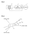
- Fig. 1 is a schematic block diagram of a motor drive system embodying the invention
- Fig. 1 is a schematic block diagram of a motor drive system embodying the invention.
- the motor drive system shown in Fig. 1 includes a motor 1, a PWM (pulse width modulation) inverter 2, and a motor control device 3.
- PWM pulse width modulation
- the motor 1 is a three-phase permanent-magnet synchronous motor provided with a rotor (unillustrated) having a permanent magnet and a stator (unillustrated) having armature windings, one for each of three phases.
- the PWM inverter (hereinafter referred to simply as the "inverter") 2 supplies three-phase alternating-current voltages, consisting of U-phase, V-phase, and W-phase voltages, to the motor 1 according to the rotor position of the motor 1. These voltages supplied to the motor 1 are collectively referred to as the motor voltage (armature voltage) V a , and the currents supplied from the inverter 2 to the motor 1 are collectively referred to as the motor current (armature current) I a .
- the motor control device 3 feeds the inverter 2 with a PWM signal for achieving desired vector control while referring to the detected motor current I a or the like.
- Fig. 2 is an analysis model diagram of the motor 1.
- armature winding should be understood to mean the armature winding provided on the motor 1.
- Fig. 2 shows the U-phase, V-phase, and W-phase armature winding fixed axes.
- Reference numeral 1a represents the permanent magnet constituting the rotor of the motor 1.
- the direction of the magnetic flux produced by the permanent magnet 1a is referred to as the d-axis
- the rotation axis for control purposes the rotation axis corresponding to the d-axis, is referred to as the ⁇ -axis.
- the axis having a phase leading the d-axis by an electrical angle of 90 degrees is referred to as the q-axis
- the axis having a phase leading the ⁇ -axis by an electrical angle of 90 degrees is referred to as the ⁇ -axis.
- the rotating coordinate system corresponding to the real axes has the d- and q-axes as its coordinate axes, and its coordinate axes are called the d-q axes.
- the rotating coordinate system for control purposes has the ⁇ - and ⁇ -axes as its coordinate axes, and its coordinate axes are called the ⁇ - ⁇ axes.
- the d-q axes rotates, and its rotation speed is represented by ⁇ .
- the ⁇ - ⁇ axes also rotates, and its rotation speed is represented by ⁇ e .
- the angle (phase) of the d-axis is represented, relative to the U-phase armature winding fixed axis, by ⁇ .
- the angle (phase) of the ⁇ -axis is represented, relative to the U-phase armature winding fixed axis, by ⁇ e .
- the angle represented by ⁇ or ⁇ e is the angle in electrical angle, and is commonly referred to as a rotor position or a magnetic pole position.
- the rotation speed represented by ⁇ or ⁇ e is the angular velocity at electrical angle.
- ⁇ or ⁇ e is referred to as a rotor position
- ⁇ or ⁇ e is referred to as a motor speed.
- the ⁇ - and ⁇ -axes can be called the axes estimated for control purposes.
- the motor control device 3 basically performs vector control such that ⁇ becomes equal to ⁇ e , it sometimes intentionally makes ⁇ different from ⁇ e .
- ⁇ is equal to ⁇ e
- the d-axis and the q-axis are equal to the ⁇ -axis and the ⁇ -axis, respectively.
- the ⁇ -axis component and the ⁇ -axis component of the motor voltage V a are referred to as the ⁇ -axis voltage V ⁇ and the ⁇ -axis voltage V ⁇ , respectively, and the ⁇ -axis component and the ⁇ -axis component of the motor current I a are referred to as the ⁇ -axis current i ⁇ and the ⁇ -axis current i ⁇ , respectively.
- the specified voltage values, or target values, of the ⁇ -axis voltage v ⁇ and the ⁇ -axis voltage v ⁇ are referred to as the specified ⁇ -axis voltage value v ⁇ * and the specified ⁇ -axis voltage value v ⁇ * , respectively.
- the specified current values, or target values, of the ⁇ -axis current i ⁇ and the ⁇ -axis current i ⁇ are referred to as the specified ⁇ -axis current value i ⁇ * and the specified ⁇ -axis current value 1 ⁇ * , respectively.
- v ⁇ * can be called a target ⁇ -axis voltage of v ⁇
- v ⁇ * can be called a target ⁇ -axis voltage of v ⁇
- i ⁇ * can be called a target ⁇ -axis current of i ⁇
- i ⁇ * can be called a target ⁇ -axis current of i ⁇ .
- the motor control device 3 performs vector control such that the values of ⁇ -axis voltage v ⁇ and ⁇ -axis voltage v ⁇ are made to follow the specified ⁇ -axis voltage value v ⁇ * and the specified ⁇ -axis voltage value v ⁇ * , respectively, and such that the values of ⁇ -axis current i ⁇ and ⁇ -axis current i ⁇ are made to follow the specified ⁇ -axis current value i ⁇ * and the specified ⁇ -axis current value i ⁇ * , respectively.
- U-, V-, and W-phase components of the motor voltage V a are represented by the specified three-phase voltage values consisting of a specified U-phase voltage value v u * , a specified V-phase voltage value v v * , and a specified W-phase voltage value v w * .
- R a represents the motor resistance (the resistance value of the armature winding of the motor 1)
- L d and Lq represent the d-axis inductance (the d-axis component of the inductance of the armature winding of the motor 1) and the q-axis inductance (the q-axis component of the inductance of the armature winding of the motor 1), respectively.
- the values of R a , L d , and Lq are determined at the time of fabrication of the motor drive system, and are used by the motor control device 3 to perform calculations.
- state quantities and the like are often referred to by their symbols (such as i ⁇ ) alone; for example, the " ⁇ -axis current i ⁇ " is sometimes referred to simply by “i ⁇ ", and these should be understood to represent the same thing.
- the terms representing the state quantities such as “current”, “voltage”, and “speed”, represent in principle the values of these state quantities. That is, for example, the " ⁇ -axis current i ⁇ " means the current value of the ⁇ -axis current (however, the wording such as "the value of the ⁇ -axis current i ⁇ " may be sometimes used).
- the motor 1 drives and rotates a load whose load torque varies periodically.
- This load is, for example, a load factor provided in a compressor (see Fig. 13 ), a washing machine (unillustrated), a drying machine (unillustrated), or the like.
- the compressor is used in an air conditioner or the like. In the compressor, a change in refrigerant gas pressure during periodic cycles of suction, compression, and discharge affects a load torque, resulting in periodic variations in load torque.
- the washing machine or the drying machine is, for example, a drum washing machine or a drum drying machine.
- a drum inside which laundry is placed rotates about a rotation axis that is not parallel to the vertical line, such that the laundry is lifted up and then dropped to remove a stain.
- the drum is a load of the motor 1
- the load torque becomes relatively large when the laundry is lifted up; otherwise it becomes relatively small. This results in periodic variations in load torque. The same holds true for the drum drying machine.
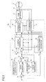
- Fig. 3 is a detailed block diagram of a motor drive system according to Example 1.
- the motor drive system shown in Fig. 3 includes the motor 1 and the inverter 2 shown in Fig. 1 , a motor control device 3a serving as the motor control device 3 shown in Fig. 1 , and a phase-current sensor 11.
- the motor control device 3a includes different parts designated with reference numerals 12 to 20 and 30 to 32.
- the motor control device 3a can be considered to include the phase-current sensor 11.
- the different parts constituting the motor control device 3a can freely use all the values produced within the motor control device 3a.
- the different parts constituting the motor drive systems of this example and other examples, which will be described later, update, at intervals of a predetermined period, the specified values (including i ⁇ * , i ⁇ * , v ⁇ * , v ⁇ * , v u * , v v * , and v w * ), the state quantities (including i u , i v , i ⁇ , i ⁇ , ⁇ e , and ⁇ e ), or the corrected ⁇ -axis current value i ⁇ C , which are calculated (or detected) thereby and outputted therefrom.
- the specified values including i ⁇ * , i ⁇ * , v ⁇ * , v ⁇ * , v u * , v v * , and v w *
- the state quantities including i u , i v , i ⁇ , i ⁇ , ⁇ e , and
- i u , i v , and i w are currents of the U-, V-, and W-phase armature windings, respectively, of the stator of the motor 1.
- the coordinate converter 12 performs coordinate conversion based on the rotor position ⁇ e so that the U-phase current i u and the V-phase current i v are converted into those on the ⁇ - ⁇ axes, and thereby calculates the ⁇ -axis current i ⁇ and the ⁇ -axis current i ⁇ and outputs them.
- the rotor position ⁇ e is calculated by the position/speed estimator 20.
- the subtracter 19 refers to the motor speed ⁇ e and the specified motor speed value ⁇ * from a specified motor speed value producing portion (unillustrated) provided outside the motor control device 3a, and calculates the speed deviation ( ⁇ * - ⁇ e ) between them.
- the motor speed ⁇ e is calculated by the position/speed estimator 20.
- the speed controller 17 calculates the specified ⁇ -axis current value i ⁇ * by using proportional-plus-integral control or the like, such that the speed deviation ( ⁇ * - ⁇ e ) converges to zero, and outputs the specified ⁇ -axis current value i ⁇ * thus calculated.
- the adder 31 adds the corrected ⁇ -axis current value i ⁇ C from the resonance filter 30 to i ⁇ * from the speed controller 17, and outputs the value (i ⁇ * + i ⁇ C ) obtained by the addition to the subtracter 13.
- the value (i ⁇ * + i ⁇ C ) is also given to the phase controller 32.
- i ⁇ * serves as a target value of i ⁇ ; in actuality, the value (i ⁇ * + i ⁇ C ) obtained by correcting i ⁇ * with the resonance filter 30 and the adder 31 serves as a target value of i ⁇ . Operations of the resonance filter 30 and the phase controller 32 will be described later.
- the magnetic flux controller 16 determines the specified ⁇ -axis current value i ⁇ * , and outputs it to the subtracter 14.
- the subtracter 14 subtracts the ⁇ -axis current i ⁇ outputted from the coordinate converter 12 from the specified ⁇ -axis current value i ⁇ * outputted from the magnetic flux controller 16, and thereby calculates the current error (i ⁇ * - i ⁇ ).
- the subtracter 13 subtracts the ⁇ -axis current i ⁇ outputted from the coordinate converter 12 from the value (i ⁇ * + i ⁇ C ) outputted from the adder 31, and thereby calculates the current error (i ⁇ * + i ⁇ C - i ⁇ ).
- the current controller 15 performs current feedback control by using proportional-plus-integral control or the like, such that the current errors (i ⁇ * - i ⁇ ) and (i ⁇ * + i ⁇ C - i ⁇ ) converge to zero.
- the specified ⁇ -axis voltage value v ⁇ * and the specified ⁇ -axis voltage value v ⁇ * are calculated by using decoupling control for eliminating interference between the ⁇ - and ⁇ -axes, such that (i ⁇ * - i ⁇ ) and (i ⁇ * + i ⁇ C - i ⁇ ) converge to zero.
- ⁇ e , i ⁇ , and i ⁇ can also be referred to at the time of calculation of v ⁇ * and v ⁇ * .
- the coordinate converter 18 performs coordinate conversion based on the rotor position ⁇ e outputted from the position/speed estimator 20 so that v ⁇ * and v ⁇ * fed from the current controller 15 are converted into those on the three-phase fixed coordinate axes, and thereby calculates the specified three-phase voltage values (v u * , v v * , and v w * ) and outputs them.
- An unillustrated PWM converter produces a PWM signal subjected to pulse width modulation in accordance with the specified three-phase voltage values (v u * , v v * , and v w * ).
- the inverter 2 supplies the motor current I a corresponding to the PWM signal to the motor 1 to drive it. More specifically, the inverter 2 includes three half-bridge circuits provided one for each of three phases and a driver, all of which are not shown in the drawing, and the driver performs on/off control for the switching devices of the half-bridge circuits in accordance with the PWM signal, such that the motor current I a according to the specified three-phase voltage values is supplied to the motor 1.
- the PWM converter is provided in the motor control device 3a; however, it can be considered to be provided in the inverter 2.
- ⁇ ⁇ - ⁇ e
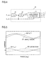
- Fig. 4 shows an example of an internal block diagram of the position/speed estimator 20.
- the position/speed estimator 20 shown in Fig. 4 includes different parts designated with reference numerals 21 to 23.
- the axis error estimator 21 calculates the axis error ⁇ based on i ⁇ , i ⁇ , v ⁇ * , and v ⁇ * .
- the axis error ⁇ is calculated by using formula (1) below, which is disclosed also in JP-B-3411878 .
- the proportional-plus-integral calculator 22 performs proportional-plus-integral control to calculate the motor speed ⁇ e such that the axis error ⁇ calculated by the axis error estimator 21 converges to zero.
- the integrator 23 integrates the motor speed ⁇ e , and thereby calculates the rotor position ⁇ e .
- the calculated ⁇ e and ⁇ e are fed to different parts of the motor control device 3 a that need them.
- ⁇ tan - 1 ⁇ - v ⁇ * - R a ⁇ i ⁇ + ⁇ e ⁇ L q ⁇ i ⁇ v ⁇ * - R a ⁇ i ⁇ + ⁇ e ⁇ L q ⁇ i ⁇
- the motor 1 drives and rotates a load whose load torque varies periodically.
- i ⁇ * may deviate from the ideal value due to variations in load torque.
- the resonance filter 30 and the adder 31 operate so as to prevent such a deviation.
- a curve 201 represents the current conversion value (current component) of a load torque
- a curve 202 represents the specified ⁇ -axis current value i ⁇ * calculated by the speed controller 17
- a curve 203 represents a waveform of error between the current conversion value of a load torque represented by the curve 201 and the specified ⁇ -axis current value i ⁇ * represented by the curve 202.
- a curve 204 represents a waveform obtained by inverting the waveform of error represented by the curve 203, and also represents a waveform of the corrected ⁇ -axis current value i ⁇ C calculated by the resonance filter 30.
- the specified ⁇ -axis current value i ⁇ * lags behind the value required to be calculated (the current conversion value of a load torque).
- the corrected ⁇ -axis current value i ⁇ C corresponding to the curve 204 is superimposed on i ⁇ * , such that (i ⁇ * + i ⁇ C ) is made identical to the current conversion value of a load torque.
- To make (i ⁇ * + i ⁇ C ) identical to the current conversion value of a load torque requires the optimization of the phase and amplitude of i ⁇ C .
- the phase controller 32 ( Fig. 3 ) is used to make adjustment for the optimization of the phase. The function of the phase controller 32 is described later. First, the function of the resonance filter 30 will be described.
- the resonance filter 30 receives a subtraction result ( ⁇ * - ⁇ e ) of the subtracter 19 as an input signal, and extracts from the input signal thus received a periodic variation component resulting from variations in load torque. Then, the resonance filter 30 outputs the extracted variation component as i ⁇ C .
- the transfer function H A (s) of the resonance filter 30 is given by formula (2) below (or formula (3), which will be described later).
- H A s ( b 0 + b 1 ⁇ s ) / s 2 + 2 ⁇ ⁇ r ⁇ s + ⁇ r 2
- b o represents a gain coefficient
- b 1 represents a phase adjusting value
- ⁇ represents an attenuation coefficient
- ⁇ r represents a natural angular frequency
- s represents the Laplace operator.
- the resonance filter 30 extracts only a frequency component of ⁇ r of the input signal, and outputs it.
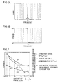
- Fig. 6A shows the gain characteristics of the resonance filter 30.
- the resonance filter 30 amplifies (emphasizes) a component of natural angular frequency ⁇ r contained in the input signal to a degree commensurate with the gain coefficient b o , and outputs it. At this time, the resonance filter 30 makes the output signal contain as few as possible a frequency component other than ⁇ r .
- Fig. 6B shows the phase characteristics of the resonance filter 30.
- the resonance filter 30 gives the component of natural angular frequency ⁇ r a phase lead of 90 degrees or more, and gives a component having a frequency lower than the natural angular frequency ⁇ r 180 degrees phase lead.
- the resonance filter 30 gives the component of natural angular frequency ⁇ r .
- the phase of a component having a frequency higher than the natural angular frequency ⁇ r is identical between the input and output signals of the resonance filter 30.
- the natural angular frequency ⁇ r is set so as to be identical (or as identical as possible) to the angular frequency of periodic load torque variations of the load of the motor 1.
- the value of the natural angular frequency ⁇ r is made to change according to the specified motor speed value ⁇ * or the value of the motor speed ⁇ e , because the period of the load torque variations changes according to the rotational speed of the motor 1.
- How to set the natural angular frequency ⁇ r according to the specified motor speed value ⁇ * or the value of the motor speed ⁇ e is previously defined at the design stage of the motor drive system.
- the motor control device 3a is previously provided with the table data for determining ⁇ r based on ⁇ * or ⁇ e .
- the attenuation coefficient ⁇ can be previously determined at the design stage of the motor drive system.
- the phase adjusting value b 1 is a value for adjusting the phase of the corrected ⁇ -axis current value i ⁇ C . Changing the phase adjusting value b 1 causes the curve 204 shown in Fig. 5 to shift in the horizontal direction.
- the gain coefficient b o changes according to the specified motor speed value ⁇ * or the value of the motor speed ⁇ e .
- How to set the gain coefficient b o according to the specified motor speed value ⁇ * or the value of the motor speed ⁇ e is previously defined at the design stage of the motor drive system.
- the motor control device 3a is previously provided with the table data for determining b o based on ⁇ * or ⁇ e .
- H A s b 0 ( 1 + b 1 ⁇ s / b 0 ) / s 2 + 2 ⁇ ⁇ r ⁇ s + ⁇ r 2
- Fig. 7 shows the measurement results (experimental results) of the variation range of (i ⁇ * + i ⁇ C ), the amplitude of a first-order component of (i ⁇ * + i ⁇ C ), and the amount of decrease or increase of power consumption, the measurement results being obtained when the phase characteristics of the resonance filter 30 are variously changed.
- the resonance filter 30 amplifies the component of natural angular frequency ⁇ r contained in the input signal while giving it a phase lead of 90 to 180 degrees, and outputs it.
- the horizontal axis represents the amount of phase lead given to the component ⁇ r by the resonance filter 30.
- the far-left and far-right portions of the horizontal axis correspond to 80 and 180 degrees, respectively.
- the vertical axis represents the current value; for a polygonal line 223, the vertical axis represents the amount of decrease or increase of power consumption.
- amount of phase lead always refers to the amount of phase lead given to the component ⁇ r by the resonance filter (in this example, the resonance filter 30).
- gain always refers to that of the resonance filter (in this example, the resonance filter 30).
- power consumption always refers to that of the motor drive system according to an embodiment.
- the amount of phase lead was changed in eight levels by changing the amount of phase adjustment b 1 (that is, the phase of the corrected ⁇ -axis current value i ⁇ C was changed in eight levels).
- the eight levels of the amount of phase lead are referred to, in order of increasing amount, as P 1 , P 2 , P 3 , P 4 , P 5 , P 6 , P 7 , and P 8 .
- the amount of phase lead is uniquely determined by setting the amount of phase adjustment b 1 . It is to be noted that P 1 , P 2 , P 3 , P 4 , P 5 , P 6 , P 7 , and P 8 are approximately 90, 100, 120, 145, 160, 170, 172, and 175 degrees, respectively.
- the polygonal line 221 shows the experimental result indicating the dependence of the variation range of (i ⁇ * + i ⁇ C ) on the amount of phase lead.
- the variation range of (i ⁇ * + i ⁇ C ) is the difference (in this case, the difference is a positive value) between the minimum and maximum values of (i ⁇ * + i ⁇ C ) observed while the motor 1 rotates one-turn in mechanical angle.
- the polygonal line 222 shows the experimental result indicating the dependence of the amplitude of the first-order component of (i ⁇ * + i ⁇ C ) on the amount of phase lead.
- the amplitude of the first-order component of (i ⁇ * + i ⁇ C ) is the amplitude of a frequency component of ⁇ t of (i ⁇ * + i ⁇ C ).
- a state in which the gain is zero is equivalent to a state in which no resonance filter 30 is provided. It is to be noted that the experiments corresponding to the polygonal lines 221 to 223 were performed with the conditions (such as b 0 and ⁇ * ) other than the amount of phase lead fixed at constant values.
- the amount of decrease or increase of power consumption behaves in a similar way. That is, as the amount of phase lead increases from 90 to 180 degrees, power consumption basically decreases; however, it is maintained largely constant when the amount of phase lead falls with the range from P 5 to P 8 . These experimental results revealed that an increase in the amount of phase lead in the range from 90 to 180 degrees basically contributes to reduction in power consumption.
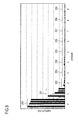
- Figs. 8 and 9 show FFT (fast Fourier transform) analysis results of (i ⁇ * + i ⁇ C ) corresponding to the experiments shown in Fig. 7 .
- the horizontal axis represents the order
- the vertical axis represents the amplitude of each order component.
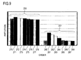
- Fig. 9 is an enlarged view of zeroth- and first-order parts of Fig. 8 .
- Fig. 8 shows FFT (fast Fourier transform) analysis results of (i ⁇ * + i ⁇ C ) corresponding to the experiments shown in Fig. 7 .
- the horizontal axis represents the order
- the vertical axis represents the amplitude of each order component.
- Fig. 9 is an enlarged view of zeroth- and first-order parts of Fig. 8 .
- bar groups marked with reference numerals 250, 251, 252, 253, 254, 255, 256, 257, 258, and 259 respectively represent the amplitudes of zeroth-, first-, second-, third-, fourth-, fifth-, sixth-, seventh-, eighth-, and ninth-order components of (i ⁇ * + i ⁇ C ).
- the zeroth-order component of (i ⁇ * + i ⁇ C ) is a direct current component of (i ⁇ * + i ⁇ C ), and the jth-order component (where j is an integer from 1 to 9) of (i ⁇ * + i ⁇ C ) is a frequency component of ( ⁇ r ⁇ j) of (i ⁇ * + i ⁇ C ).
- Each bar group consists of nine bars.
- the height of the leftmost bar represents the amplitude observed when the gain is zero.
- the second to ninth bars from the left each represent the amplitude observed when a constant gain, which is not zero, is given, and, the closer to the right a bar is located, the greater the corresponding amount of phase lead. That is, in Fig.
- the heights of bars 271, 272, 273, 274, 275, 276, 277, and 278 represent the amplitudes of the zeroth-order component of (i ⁇ * + i ⁇ C ) observed when the amount of phase lead is P 1 , P 2 , P 3 , P 4 , P 5 , P 6 , P 7 , and P 8 , respectively, and the heights of bars 281, 282, 283, 284, 285, 286, 287, and 288 represent the amplitudes of the first-order component of (i ⁇ * + i ⁇ C ) observed when the amount of phase lead is P 1 , P 2 , P 3 , P 4 , P 5 , P 6 , P 7 , and P 8 , respectively.
- the height of the bar 270 represents the amplitude of the zeroth-order component of (i ⁇ * + i ⁇ C ) observed when the gain is zero
- the height of the bar 280 represents the amplitude of the first-order component of (i ⁇ * + i ⁇ C ) observed when the gain is zero.
- the power consumption is considered to be minimized by minimizing the amplitude of the first-order component of (i ⁇ * + i ⁇ C ).
- the amount of phase lead with which the amplitude of the first-order component of (i ⁇ * + i ⁇ C ) is minimized is in general considered to be identical to the amount of phase lead with which the variation range of (i ⁇ * + i ⁇ C ) is minimized. Therefore, minimization of power consumption may be achieved by minimizing the variation range of (i ⁇ * + i ⁇ C ), instead of minimizing the amplitude of the first-order component of (i ⁇ * + i ⁇ C ).
- i ⁇ * 0 and i ⁇ * >> i ⁇ *
- a power loss of the motor drive system is roughly proportional to the square of the ⁇ -axis current i ⁇ ( ⁇ i ⁇ * + i ⁇ C ).
- i ⁇ * 0 and i ⁇ * >> i ⁇ *
- a power loss of the motor drive system is roughly proportional to the square of the ⁇ -axis current i ⁇ ( ⁇ i ⁇ * + i ⁇ C ).
- the phase controller 32 shown in Fig. 3 calculates, based on (i ⁇ * + i ⁇ C ) outputted from the adder 31, the amount of phase adjustment b 1 for minimizing the variation range of (i ⁇ * + i ⁇ C ) or the amplitude of the first-order component of (i ⁇ * + i ⁇ C ).
- the resonance filter 30 calculates the corrected ⁇ -axis current value i ⁇ C by using the amount of phase adjustment b 1 thus calculated, and outputs the corrected ⁇ -axis current value i ⁇ C .
- the phase controller 32 adjusts the phase of the corrected ⁇ -axis current value i ⁇ C by controlling the resonance filter 30 (specifically, by adjusting b 1 ), thereby achieving minimization of power consumption.
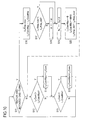
- Fig. 10 is a flow chart showing the procedure for minimizing the variation range of (i ⁇ * + i ⁇ C ). This procedure is based on a so-called hill-climbing algorithm.
- the most current value of (i ⁇ * + i ⁇ C ) is successively assigned to a variable i ⁇ Com.
- a variable i ⁇ ComMax to which a maximum value of i ⁇ Com is assigned and a variable i ⁇ ComMin to which a minimum value of i ⁇ Com is assigned are adopted, and a variable i ⁇ Amp_now to which the variation range of the current i ⁇ Com is assigned and a variable i ⁇ Amp_old to which the variation range of the last i ⁇ Com is assigned are adopted.
- the amount of phase adjustment b 1 used by the resonance filter 30 is treated as a variable, and b 1 can be sequentially updated.
- the amount of change in variable b 1 per change is ⁇ .
- the initial values of the variables i ⁇ ComMax, i ⁇ ComMin, i ⁇ Amp_now, and i ⁇ Amp_old are set at zero.
- the initial value of the variable b 1 is set at a predetermined value.
- Steps S11 to S20 are performed by the phase controller 32 every time the variable i ⁇ Com is updated.
- step S11 it is checked whether or not the rotor of the motor 1 has rotated one-turn from a given base point in time. Here, rotating "one-turn" is not rotating one-turn in electrical angle but rotating one-turn in mechanical angle. If the rotor of the motor 1 is found not to have rotated one-turn, the procedure proceeds to step S12, and it is checked whether or not the current variable i ⁇ Com is greater than the current variable i ⁇ ComMax. If i ⁇ Com > i ⁇ ComMax, the procedure proceeds to step S14. In step S14, the current variable i ⁇ Com is assigned to the variable i ⁇ ComMax, and the procedure proceeds to step S 13. On the other hand, if i ⁇ Com ⁇ i ⁇ ComMax, the procedure directly proceeds to step S13.
- step S 13 it is checked whether or not the current variable i ⁇ Com is smaller than the current variable i ⁇ ComMin. If i ⁇ Com ⁇ i ⁇ ComMin, the procedure proceeds to step S15. In step S15, the current variable i ⁇ Com is assigned to the variable i ⁇ ComMin, and the procedure goes back to step S11. On the other hand, if i ⁇ Com ⁇ i ⁇ ComMin, the procedure directly goes back to step S 11.
- step S11 if the rotor of the motor 1 is found to have rotated one-turn from the base point in time, the procedure proceeds to step S 16.
- the maximum and minimum values of the variable i ⁇ com obtained during one turn of the rotor are assigned to the variables i ⁇ ComMax and i ⁇ ComMin, respectively.
- step S16 (i ⁇ ComMax - i ⁇ ComMin) is assigned to the variable i ⁇ Amp_now.
- step S 17 it is checked whether or not an inequality i ⁇ Amp_now ⁇ i ⁇ Amp_old holds. If this inequality is found to hold, the procedure directly proceeds to step S19. On the other hand, if this inequality is found not to hold, the procedure proceeds to step S 18, and a value obtained by multiplying the current variable ⁇ by -1 is newly assigned to the variable ⁇ . Then, the procedure proceeds to step S19.
- step S19 a variable ⁇ is added to the current variable b 1 , and a value thus obtained serves as a new variable b 1 .
- the variable b 1 thus updated is transmitted to the resonance filter 30, and is used as the amount of phase adjustment b 1 when calculating the corrected ⁇ -axis current value i ⁇ C .
- step S20 zero is assigned to the variable i ⁇ ComMax, a maximum value MAX of the variable i ⁇ ComMin is assigned to the variable i ⁇ ComMin, and a value of the current variable i ⁇ Amp_now is assigned to the variable i ⁇ Amp_old. Then, the procedure goes back to step S12. It is assumed that the variable i ⁇ ComMin takes on various values.
- the maximum value MAX here is the maximum of the various values that the variable i ⁇ ComMin is assumed to take on.
- a time point at which the procedure goes back from step S20 to step S12 serves as a base point in time used as the reference for the next branching process in step S 11.
- the variation range of (i ⁇ * + i ⁇ C ) is kept at or near a minimum value (local minimum, to be exact).
- ⁇ r in the transfer function of the resonance filter 30 naturally leads to a change in a frequency component at which reduction in vibration can be achieved by using the resonance filter 30.
- load torque variations contain a plurality of frequency components; in general, ⁇ r is determined so as to adapt to a frequency component having the largest amplitude of those of the plurality of frequency components.
- compressors to which the motor drive system is applied are a single-stage compressor and a two-stage compressor.
- ⁇ r is basically set so as to be n times as large as ⁇ e (or ⁇ * ) that is an operating frequency of the motor 1.
- n is an integer such as 1 or 2
- an n-stage compressor is a compressor that performs n cycles of suction, compression, and discharge while the motor 1 rotates one-turn in mechanical angle.
- Fig. 11 is a detailed block diagram of a motor drive system according to Example 2.
- the motor drive system shown in Fig. 11 includes the motor 1 and the inverter 2, which are shown in Fig. 1 , a motor control device 3b serving as the motor control device 3 shown in Fig. 1 , and the phase-current sensor 11.
- the motor control device 3b includes different parts designated with reference numerals 12 to 20 and 30 to 32.
- the motor control device 3b can be considered to include the phase-current sensor 11.
- the different parts constituting the motor control device 3b can freely use all the values produced within the motor control device 3b.
- the resonance filter 30 receives a speed deviation ( ⁇ * - ⁇ e ) as an input signal.
- the resonance filter 30 receives, as an input signal, the specified ⁇ -axis current value i ⁇ * from the speed controller 17 instead of a speed deviation ( ⁇ * - ⁇ e ).
- the resonance filter 30 extracts from i ⁇ * a periodic variation component resulting from variations in load torque, and outputs the variation component thus extracted to the adder 31 as i ⁇ C .
- the motor control devices 3a and 3b differ only in the input signal of the resonance filter 30; in other respects, they are identical with each other.
- Fig. 12 is a detailed block diagram of a motor drive system according to Example 3.
- the motor drive system shown in Fig. 12 includes the motor 1 and the inverter 2, which are shown in Fig. 1 , a motor control device 3c serving as the motor control device 3 shown in Fig. 1 , and the phase-current sensor 11.
- the motor control device 3c includes different parts designated with reference numerals 12 to 20, 31, and 32, and a resonance filter 30c.
- the motor control device 3c can be considered to include the phase-current sensor 11.
- the different parts constituting the motor control device 3c can freely use all the values produced within the motor control device 3c.
- the resonance filter 30 calculates the corrected ⁇ -axis current value i ⁇ C from the speed deviation ( ⁇ * - ⁇ e ).
- the resonance filter 30c calculates the corrected ⁇ -axis current value i ⁇ C from the axis error ⁇ .
- the motor control devices 3a and 3c differ only in the resonance filter; in other respects, they are identical with each other. In the following description, only the resonance filter 30c and input and output thereof are explained, and the explanations of such parts as are found in both the motor control devices 3a and 3c will be omitted.
- the resonance filter 30c receives the axis error ⁇ estimated by the position/speed estimator 20 as an input signal, and extracts from the axis error ⁇ a periodic variation component resulting from variations in load torque. Then, the resonance filter 30c outputs the variation component thus extracted as a corrected ⁇ -axis current value i ⁇ C .
- b o represents a gain coefficient
- b 1 represents a phase adjusting value
- ⁇ represents an attenuation coefficient
- ⁇ r represents a natural angular frequency
- s represents the Laplace operator.
- the resonance filter 30c amplifies (emphasizes) a frequency component of ⁇ r of the input signal to a degree commensurate with the gain coefficient b o , and outputs it. Ideally, the resonance filter 30c extracts only a frequency component of ⁇ r of the input signal, and outputs it.
- the degree of emphasis that is, the gain of the resonance filter 30c, is determined by the gain coefficient b o .
- the resonance filter 30c gives a component of natural angular frequency ⁇ r contained in the input signal a phase lead in the range from 90 to 180 degrees, and the amount of phase lead is determined by b 1 .
- the adder 31 calculates the sum (i ⁇ * + i ⁇ C ) of the specified ⁇ -axis current value i ⁇ * from the speed controller 17 and the corrected ⁇ -axis current value i ⁇ C from the resonance filter 30c, and outputs it to the subtracter 13.
- the phase controller 32 adjusts the amount of phase adjustment b 1 used by the resonance filter 30c based on the output value (i ⁇ * + i ⁇ C ) of the adder 31, such that the variation range of (i ⁇ * + i ⁇ C ) or the amplitude of the first-order component of (i ⁇ * + i ⁇ C ) is minimized, and thereby adjusts the phase of the corrected ⁇ -axis current value i ⁇ C .
- the phase controller 32 adjusts the amount of phase adjustment b 1 used by the resonance filter 30c based on the output value (i ⁇ * + i ⁇ C ) of the adder 31, such that the variation range of (i ⁇ * + i ⁇ C ) or the amplitude of the first-order component of (i ⁇ * + i ⁇ C ) is minimized, and thereby adjusts the phase of the corrected ⁇ -axis current value i ⁇ C .
- the axis error ⁇ is inputted to the resonance filter 30c.
- a value of any other type may be inputted to the resonance filter 30c as long as it varies in synchronism with variations in the axis error ⁇ (variations in the axis error ⁇ at a natural angular frequency ⁇ r ), because the value varying in synchronism with variations in the axis error ⁇ contains, as is the case with the axis error ⁇ , a periodic variation component synchronized with periodic variations in load torque.
- a signal that is proportional (or substantially proportional) to the axis error ⁇ may be inputted to the resonance filter 30c.
- a torque variation component ⁇ Tm estimated by using the axis error ⁇ may be inputted to the resonance filter 30c as an input signal.
- the torque variation component ⁇ Tm is an approximate value calculated by, for example, formula (6) below, it can be considered to be proportional to the axis error ⁇ .
- P represents the number of poles of the motor 1
- J represents inertia.
- the torque variation component ⁇ Tm corresponds to the result of subtraction of a load torque from a torque produced by the motor 1, and the torque produced by the motor 1 cannot follow periodic variations in load torque, causing torque variations to occur (that is, preventing ⁇ Tm from becoming zero).
- the torque variation component ⁇ Tm causes variations in speed, resulting in variations in the axis error ⁇ .
- Examples 1 to 3 deal with the motor drive systems in which vector control is performed such that the axis error ⁇ between the d-axis and the ⁇ -axis is made to converge to zero, that is, such that the ⁇ -axis is made to follow the d-axis; however, Examples 1 to 3 may be modified to be Example 4 in which vector control is performed such that the ⁇ -axis is made to follow an axis other than the d-axis.
- vector control may be performed such that the ⁇ -axis is made to follow the dm-axis.
- the dm-axis is an axis that lags behind a qm-axis by an electrical angle of 90 degrees.
- the qm-axis is the rotation axis whose direction coincides with that of the current vector to be fed to the motor 1 when maximum torque control is achieved.
- the current vector to be fed to the motor 1 is the current to be fed to the motor 1, the current being expressed in vector form.
- the qm-axis may be the rotation axis having a phase leading the rotation axis whose direction coincides with that of the current vector to be fed to the motor 1 when maximum torque control is achieved.
- the position/speed estimator 20 shown in Fig. 3 and other drawings estimates the axis error ⁇ m between the dm-axis and the ⁇ -axis by using all or part of i ⁇ , i ⁇ , v ⁇ * and v ⁇ * , and estimates the rotor position ⁇ e and the rotation speed ⁇ e such that the axis error ⁇ m is made to converge to zero by using proportional-plus-integral control.
- Examples 1 to 4 deal with the motor drive systems in which position sensorless vector control is performed that uses no position sensor for detecting the rotor position. However, the techniques described in Examples 1 to 4 are useful in a case where the position sensor is provided. As Example 5 of the invention, a description will be given below of a motor drive system provided with the position sensor. Any feature of Examples 1 to 4 can be applied, unless inconsistent, to Example 5.
- a configuration (unillustrated) of a motor drive system that differs from the motor drive system shown in Fig. 3 according to Example 1 in that a position sensor is further added will be described.
- the motor drive system according to Example 5 differs from the motor drive system shown in Fig. 3 in that ⁇ e and ⁇ e are detected based on the output signal of the position sensor, and that this eliminates the need for the estimator 20. In other respects, this motor drive system is the same as that shown in Fig. 3 .
- the position sensor is realized with, for example, Hall devices or resolvers, and outputs a signal for specifying the magnetic pole position of the permanent magnet 1a of the rotor of the motor 1 (that is, a signal for specifying the rotor position ⁇ ).
- the phase of the d-axis, relative to the U-phase armature winding fixed axis, is detected based on the output signal of the position sensor.
- the phase (rotor position) thus detected is treated as ⁇ e .
- This rotor position ⁇ is, ideally, identical to ⁇ shown in Fig. 2 , and is fed to the coordinate converters 12 and 18.
- the rotor position ⁇ e is differentiated by a speed calculating differentiator (unillustrated) to obtain ⁇ e , and ⁇ e thus obtained is fed to the subtracter 19 and the current controller 15.
- Example 5 It is needless to say that the same effects as those achieved in Example 1 can be achieved by configuring the motor drive system as in Example 5.
- a compressor 300 is shown in Fig. 13.
- Fig. 13 is an external view of the compressor 300. Any one of the motor drive systems according to Examples 1 to 5 is provided in the compressor 300.
- the compressor 300 compresses refrigerant gas (unillustrated) by using a torque of the motor 1 (a torque produced by the motor 1) as its drive source.
- the compressor 300 is a scroll compressor.
- a pair of scrolls (unillustrated) of identical shape are provided inside the compressor 300.
- One of the scrolls is fixed, and the other is made to orbit eccentrically by a torque of the motor 1.
- gases such as refrigerant gas
- sucking and discharge of the gas is performed.
- a load that is directly driven by the torque of the motor 1 is the scroll.
- the scroll compressor itself can be considered to be a load of the motor 1.
- the compressor 300 may be a compressor other than a scroll compressor, such as a reciprocating compressor or a rotary compressor.
- the compressor 300 is a reciprocating compressor
- the compressor 300 has a piston and a cylinder forming a compression space, and the piston is made to reciprocate in the cylinder by the torque of the motor 1.
- gases such as refrigerant gas
- a load that is directly driven by the torque of the motor 1 is the piston.
- the reciprocating compressor itself can be considered to be a load of the motor 1.
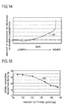
- Figs. 14 and 15 each show the experimental results conducted for the motor drive system shown in Fig. 3 .
- the motor speed ( ⁇ e ) varies greatly due to load torque variations.
- the resonance filter 30 By providing the resonance filter 30, it is possible to reduce the amount of variation in motor speed.
- the rate of reduction of variation in motor speed relative to the amount of variation in motor speed observed when no resonance filter 30 is provided is referred to as the speed variation reduction rate.
- the amount of variation in motor speed observed when no resonance filter 30 is provided is 100.
- the amount of variation in motor speed when the speed variation reduction rate is 30 % is 70. Since variation in motor speed causes vibration of the compressor or the like, the higher the speed variation reduction rate, the greater vibration-reduction effect.
- a polygonal line 402 shown in Fig. 15 represents the experimental results indicating the dependence of the speed variation reduction rate on the amount of phase lead in the motor control system shown in Fig. 3 . It is to be noted that the experiments to obtain the polygonal line 402 were performed with the conditions (such as b 0 and ⁇ * ) other than the amount of phase lead fixed at constant values. These experimental results revealed that, when the amount of phase lead is 90 degrees, the speed variation reduction rate reaches a maximum, and, as the amount of phase lead increases from 90 to 180 degrees, the speed variation reduction rate decreases.
- the first term in the right side of formula (9) represents a power loss due to the motor resistance, and the second term in the right side thereof represents power involved in the occurrence of torque. Due to the presence of the first term that is proportional to i q 2 , an increase in the harmonic components contained in iq leads to an increase in loss and hence in power consumption. In a case where the ⁇ - ⁇ axes is made to follow the d-q axes as in Example 1, since iq follows (i ⁇ * + i ⁇ C ), by reducing the harmonic components (in particular, the first-order component which is the most dominant of them all) of (1 ⁇ * + i ⁇ C ), it is possible to reduce power consumption.
- a simulation is performed in order to study the relationship between power consumption and the gain and amount of phase lead of the resonance filter 30 by modeling the motor control system shown in Fig. 3 or 11 .
- P W given by formula (9) and fr given by formula (10b) are considered as functions of the amplitude A 2 , and are expressed as P W (A 2 ) and fr(A 2 ), respectively.
- a function value of P W (A 2 ) for different amplitudes A 2 was obtained.
- a curve 411 shown in Fig. 16 represents the relationship between A 2 and P W (A 2 ) indicating the simulation results.
- P W given by formula (9) and fr given by formula (10b) are considered as functions of the phase Q, and are expressed as P W (Q) and fr(Q), respectively.
- a curve 412 shown in Fig. 17 represents the relationship between Q and P W (Q) indicating the simulation results.
- R a 0.1 ⁇
- ⁇ 2 ⁇ ⁇ ⁇ 30 rad/s
- CONST 6.5 A
- ⁇ a 0.107 Wb
- a 1 7 A
- a 2 4 A
- Q was changed in the range of 2 ⁇ ⁇ ⁇ 90/360 rad ⁇ Q ⁇ 2 ⁇ ⁇ 180/360 rad.
- P W Q R a ⁇ fi + fr Q 2 + ⁇ a ⁇ fi + fr Q
- fr given by formula (10b) is considered as a function of the amplitude A 2 , and is expressed as fr(A 2 ).
- a function value of the combined waveform F(A 2 ) for different amplitudes A 2 was obtained.
- Q 2 ⁇ ⁇ 100/360 rad
- a 2 was changed in the range of 0 A ⁇ A 2 ⁇ 8 A.
- F ( A 2 ) fi + fr A 2
- Fig. 18 is the simulation results corresponding to formula (13).
- the horizontal axis represents time
- the vertical axis represents a value of the combined waveform F(A 2 ) at each time.
- the amplitude A 2 is increased by increasing the gain, the amplitude of the combined waveform F(A 2 ) is temporarily reduced. As a result, it is expected that power consumption is also reduced.
- the gain is further increased, the amplitude of the combined waveform F(A 2 ) gradually begins to increase. As a result, it is expected that power consumption also increases.
- fr given by formula (10b) is considered as a function of the phase Q, and is expressed as fr(Q).
- a 2 4 A
- Q was changed in the range of 2 ⁇ ⁇ ⁇ 90/360 rad ⁇ Q ⁇ 2 ⁇ ⁇ 180/360 rad.
- F ( Q ) fi + fr Q
- Fig. 19 is the simulation results corresponding to formula (14).
- the horizontal axis represents time
- the vertical axis represents a value of the combined waveform F(Q) at each time.
- the phase Q leads, the amplitude of the combined waveform F(A 2 ) is reduced. As a result, it is expected that power consumption also decreases.
- a three-dimensional surface 470 shown in Fig. 20 represents the results of this simulation.
- a region 471 corresponds to a state in which the resonance filter is hardly functioning. If the amount of phase lead is set to 90 degrees while the gain of the resonance filter is sufficiently high, power consumption is maximized (corresponding to a region 472); if the amount of phase lead is set to 180 degrees while the gain of the resonance filter is sufficiently high, power consumption is minimized (corresponding to a region 473).
- the amount of phase lead when the amount of phase lead is 180 degrees, the variation range of (i ⁇ * + i ⁇ C ) is minimized, whereby power consumption is minimized.
- the amount of phase lead to minimize the variation range of (i ⁇ * + i ⁇ C ) or the amplitude of the first-order component of (i ⁇ * + i ⁇ C ) is not always 180 degrees, and it can vary depending on various factors including the motor speed and the mechanical structure of an appliance into which the motor drive system is incorporated. According to the motor drive systems of Examples 1 to 5, however, the amount of phase lead is automatically adjusted so as to reduce power consumption with consideration given to these various factors.
- Example 8 With consideration given to such a case, the following application is beneficial. This application is explained as Example 8. With reference to Fig. 3 , a case in which this application is applied to the motor drive system of Example 1 will be discussed.
- a mode setting portion (unillustrated) is provided in the motor control device 3a, the motor drive system, or an appliance into which the motor drive system is incorporated.
- the user is allowed to select, from among a plurality of operation modes, an operation mode of the appliance into which the motor drive system is incorporated by performing operation for the mode setting portion.
- the plurality of operation modes include a power consumption priority mode and a vibration suppression priority mode.
- Information for identifying the selected operation mode is called mode selection information.
- the mode selection information is transmitted to the motor control device 3a.
- the mode selection information indicating that mode is transmitted to the motor control device 3a.
- the phase controller 32 minimizes the variation range of (i ⁇ * + i ⁇ C ) or the amplitude of the first-order component of (i ⁇ * + i ⁇ C ) by adjusting the amount of phase lead, which has been described in Example 1, thereby achieves minimization of power consumption.
- the mode selection information indicating that mode is transmitted to the motor control device 3a.
- the phase controller 32 adjusts the amount of phase lead of the resonance filter 30 in the direction in which the variation range of (i ⁇ * + i ⁇ C ) or the amplitude of the first-order component of (i ⁇ * + i ⁇ C ) increases.
- the amount of phase lead is adjusted by using a hill-climbing algorithm or the like, such that the variation range of (i ⁇ * + i ⁇ C ) or the amplitude of the first-order component of (i ⁇ * + i ⁇ C ) is maximized within the phase lead amount adjustable range.
- Adjustment for the amount of phase lead is performed, in actuality, by adjusting the amount of phase adjustment b 1 . Since the direction in which the amount of phase lead is changed for reducing power consumption is basically opposite to the direction in which the amount of phase lead is changed for reducing vibration, the amount of phase lead of the resonance filter 30 is adjusted in the direction in which the variation range of (i ⁇ * + i ⁇ C ) or the amplitude of the first-order component of (i ⁇ * + i ⁇ C ) increases. This makes it possible to obtain a greater vibration-reduction effect.
- the phase controller 32 may control the resonance filter 30 as follows.
- the phase controller 32 may control the resonance filter 30 as follows.
- phase controller 32 is not required to use (i ⁇ * + i ⁇ C ) in controlling the resonance filter 30. That is, in this case, the phase controller 32 controls the phase of i ⁇ C by controlling the resonance filter 30 based not on (i ⁇ * + i ⁇ C ) but on the mode selection information.
- the plurality of operation modes may include other operation modes.
- a mode intermediate between the power consumption priority mode and the vibration suppression priority mode may be provided.
- power consumption is at a level between power consumption achieved when the power consumption priority mode is selected and power consumption achieved when the vibration suppression priority mode is selected
- vibration is at a level between the level of vibration achieved when the power consumption priority mode is selected and the level of vibration achieved when the vibration suppression priority mode is selected.
- Example 8 can be applied to the motor drive systems of Examples 1 to 5.
- Example 8 In a case where Example 8 is applied to Example 2, it is simply necessary to replace reference character 3a appearing in the above description of Example 8 with reference character 3b; in a case where Example 8 is applied to Example 3, it is simply necessary to replace reference characters 3a and 30 appearing in the above description of Example 8 with reference characters 3c and 30c.
- the embodiment described above deals with a method of adjusting the phase of i ⁇ C . Concurrent with this phase adjustment, the gain of the resonance filter (30 or 30c) may be adjusted.
- any of the different specified values (such as i ⁇ * , i ⁇ * , v ⁇ * , and v ⁇ * ) and state quantities (such as i ⁇ and i ⁇ ) mentioned above, that is, any value that needs to be derived as necessary may be derived in any manner. That is, such values may be derived, for example, through calculation performed within the motor control device (3a, 3b, or 3c), or may be derived from a previously set table data.
- the embodiment described above deals with a case in which the U-phase current i u and the V-phase current i v are directly detected by using the phase-current sensor 11; however, it is also possible to detect them based on the direct current on the power supply side of the inverter 2.
- Part or all of the functions of the motor control device (3a, 3b, or 3c) is realized, for example, with software (program) incorporated in a general-purpose microcomputer or the like.
- software program
- the block diagrams showing the configurations of different parts of the motor control device serve as functional block diagrams.
- the motor control device may be realized with hardware alone, instead of software (program), or may be realized with a combination of software and hardware.
- the position/speed estimator 20 shown in Fig. 3 and other drawings serves as a motor speed deriving portion that derives the motor speed ⁇ e by estimation.
- the aforementioned speed calculating differentiator (unillustrated) serves as the motor speed deriving portion, and this speed calculating differentiator detects the motor speed ⁇ e in collaboration with the position sensor (the motor speed deriving portion may be considered to include the position sensor).
- the specified ⁇ -axis current value i ⁇ * is a specified value for a current component related to the torque of the motor 1, it can be called a specified torque current value.
- the corrected ⁇ -axis current value i ⁇ C can be called a corrected torque current value.
- the phase controller 32 shown in Fig. 3 and other drawings serves as an adjusting portion that adjusts the phase of the corrected torque current value by controlling the resonance filter (30 or 30c), and the adder 31 shown in Fig. 3 and other drawings serves as a torque current corrector.
Landscapes
- Engineering & Computer Science (AREA)
- Power Engineering (AREA)
- Mechanical Engineering (AREA)
- General Engineering & Computer Science (AREA)
- Control Of Ac Motors In General (AREA)
Applications Claiming Priority (1)
| Application Number | Priority Date | Filing Date | Title |
|---|---|---|---|
| JP2007210307A JP4476314B2 (ja) | 2007-08-10 | 2007-08-10 | モータ制御装置及び圧縮機 |
Publications (2)
| Publication Number | Publication Date |
|---|---|
| EP2023480A2 true EP2023480A2 (de) | 2009-02-11 |
| EP2023480A3 EP2023480A3 (de) | 2017-04-19 |
Family
ID=40042944
Family Applications (1)
| Application Number | Title | Priority Date | Filing Date |
|---|---|---|---|
| EP08014147.6A Withdrawn EP2023480A3 (de) | 2007-08-10 | 2008-08-07 | Verdichter und Vorrichtung für eine Motorsteuerung |
Country Status (4)
| Country | Link |
|---|---|
| US (1) | US8084977B2 (de) |
| EP (1) | EP2023480A3 (de) |
| JP (1) | JP4476314B2 (de) |
| CN (1) | CN101364785B (de) |
Cited By (8)
| Publication number | Priority date | Publication date | Assignee | Title |
|---|---|---|---|---|
| WO2015042675A3 (en) * | 2013-09-25 | 2015-05-21 | Whirlpool S.A. | System and method for controlling the operation of an electric motor of a compressor |
| US9356544B2 (en) | 2012-06-04 | 2016-05-31 | Siemens Aktiengesellschaft | Control device for eliminating malfunctions in a network |
| EP3098448A1 (de) * | 2015-05-29 | 2016-11-30 | MAN Truck & Bus AG | Verfahren und regelkreis zur regelung eines elektrischen antriebs eines elektrisch angetriebenen druckluftverdichters eines kraftfahrzeugs |
| EP3115606A1 (de) | 2015-07-07 | 2017-01-11 | Whirlpool S.A. | Verfahren und system zum schutz eines resonanten linearverdichters |
| EP3199809A1 (de) * | 2016-01-28 | 2017-08-02 | ABB Technology Oy | Steuerungsverfahren für ein verdichtersystem |
| EP4105481A1 (de) * | 2021-06-15 | 2022-12-21 | LG Electronics Inc. | Vorrichtung zum steuern eines kompressors, kompressor und verfahren zum steuern eines kompressors |
| CN115684929A (zh) * | 2022-12-01 | 2023-02-03 | 常州百康特医疗器械有限公司 | 用于旋切活检设备驱动模块的实时变加载装置及系统 |
| CN119492134A (zh) * | 2024-10-09 | 2025-02-21 | 珠海格力电器股份有限公司 | 压缩机的定位方法、电子设备和压缩机 |
Families Citing this family (40)
| Publication number | Priority date | Publication date | Assignee | Title |
|---|---|---|---|---|
| JP2007336641A (ja) * | 2006-06-13 | 2007-12-27 | Denso Corp | 同期モータの位置センサレス駆動装置 |
| JP4928850B2 (ja) * | 2006-06-28 | 2012-05-09 | 株式会社東芝 | 回転機制御装置 |
| JP4297953B2 (ja) * | 2007-06-22 | 2009-07-15 | 三洋電機株式会社 | モータ制御装置及び圧縮機 |
| JP2009303435A (ja) * | 2008-06-17 | 2009-12-24 | Sanyo Electric Co Ltd | モータ制御装置 |
| JP5393238B2 (ja) * | 2009-04-28 | 2014-01-22 | 株式会社日立製作所 | 電動機駆動システム,電動機制御装置及び電動機の駆動方法 |
| EP2278062B1 (de) * | 2009-07-14 | 2014-06-18 | Electrolux Home Products Corporation N.V. | Sensorloses Sicherheitssystem zur Bestimmung der Drehung einer elektrischen Haushaltsgerät-Wäschetrommel, die von einem asynchronen Dreiphasen-Motor betrieben wird |
| JP5213890B2 (ja) * | 2010-02-23 | 2013-06-19 | 三菱電機株式会社 | モータ駆動装置及び圧縮機及び冷凍サイクル装置及び洗濯機及び洗濯乾燥機及び送風機 |
| JP5175887B2 (ja) * | 2010-03-23 | 2013-04-03 | 株式会社東芝 | モータ制御装置及び電気機器 |
| KR101628385B1 (ko) * | 2010-03-31 | 2016-06-08 | 현대자동차주식회사 | 영구자석 동기모터의 제어방법 |
| WO2012029099A1 (ja) * | 2010-08-30 | 2012-03-08 | 三菱電機株式会社 | ヒートポンプ装置、ヒートポンプシステム及び三相インバータの制御方法 |
| JP5652664B2 (ja) * | 2011-10-21 | 2015-01-14 | アイシン・エィ・ダブリュ株式会社 | 回転電機制御装置 |
| WO2013136612A1 (ja) * | 2012-03-16 | 2013-09-19 | 三菱電機株式会社 | 角度検出装置 |
| JPWO2014010020A1 (ja) * | 2012-07-09 | 2016-06-20 | 株式会社安川電機 | モータ制御装置及びモータシステム |
| JP5411331B1 (ja) * | 2012-08-21 | 2014-02-12 | 山洋電気株式会社 | モータ制御装置 |
| JP6078300B2 (ja) * | 2012-11-07 | 2017-02-08 | カルソニックカンセイ株式会社 | 電動コンプレッサの制御装置 |
| CN103967794B (zh) * | 2013-02-05 | 2016-01-20 | 广东美的制冷设备有限公司 | 一种单转子压缩机的振动补偿方法及控制器 |
| US9816742B2 (en) * | 2013-03-13 | 2017-11-14 | Trane International Inc. | Variable frequency drive apparatuses, systems, and methods and controls for same |
| DE102013109412A1 (de) * | 2013-08-29 | 2015-03-05 | Prominent Gmbh | Verfahren zur Verbesserung von Dosierprofilen von Verdrängerpumpen |
| DE102013109411A1 (de) * | 2013-08-29 | 2015-03-05 | Prominent Gmbh | Verfahren zur Bestimmung von hydraulischen Parametern |
| DE102013109410A1 (de) * | 2013-08-29 | 2015-03-19 | Prominent Gmbh | Verfahren zur Bestimmung einer physikalischen Größe in einer Verdrängerpumpe |
| CN104660138B (zh) * | 2013-11-20 | 2018-09-11 | 广东美的制冷设备有限公司 | 永磁同步电机的零速保护装置及零速检测方法 |
| CN105083057A (zh) * | 2014-04-25 | 2015-11-25 | 德昌电机(深圳)有限公司 | 座椅位置调节系统及方法 |
| CN104201964B (zh) * | 2014-09-12 | 2017-09-01 | 东南大学 | 一种磁通切换直线电机速度脉动抑制方法 |
| JP2016189668A (ja) * | 2015-03-30 | 2016-11-04 | Juki株式会社 | モータ制御装置、モータ制御方法、ミシン及びそのプログラム |
| US10330099B2 (en) * | 2015-04-01 | 2019-06-25 | Trane International Inc. | HVAC compressor prognostics |
| DE102016111101A1 (de) * | 2016-06-17 | 2017-12-21 | Knorr-Bremse Systeme für Schienenfahrzeuge GmbH | Verfahren und Einrichtung zur Schwingungskompensation bei einem Kolbenkompressor |
| JP6735622B2 (ja) * | 2016-07-22 | 2020-08-05 | 日立ジョンソンコントロールズ空調株式会社 | モータ駆動装置、及び、それを用いた冷凍空調機器 |
| KR20200019590A (ko) * | 2016-09-16 | 2020-02-24 | 워너 엔지니어링 인코포레이티드 | 용적형 펌프 및 제어 시스템 |
| CN107091516B (zh) * | 2017-06-08 | 2019-10-08 | 广东美的暖通设备有限公司 | 电流控制方法、电流控制系统和空调器 |
| CN110809504A (zh) * | 2017-06-16 | 2020-02-18 | 松下知识产权经营株式会社 | 冲击式电动工具 |
| CN107565862B (zh) * | 2017-09-08 | 2019-09-24 | 华中科技大学 | 一种适用于永磁同步电机的速度波动抑制方法 |
| US11518247B2 (en) * | 2017-12-28 | 2022-12-06 | Mitsubishi Electric Corporation | Electric vehicle controller |
| JP7058562B2 (ja) * | 2018-06-07 | 2022-04-22 | 株式会社コロナ | モータ制御装置および空気調和装置 |
| KR102589984B1 (ko) * | 2018-08-31 | 2023-10-16 | 주식회사 디엔솔루션즈 | 공작기계의 공진억제 제어장치 및 공진억제 제어방법 |
| DE102018125999A1 (de) * | 2018-10-19 | 2020-04-23 | OET GmbH | Verfahren zur Steuerung eines Scrollverdichters und Steuerungsvorrichtung für einen Scrollverdichter |
| CN109713965B (zh) * | 2018-12-13 | 2021-10-29 | 青岛海尔空调器有限总公司 | 一种抑制空调压缩机转速波动的方法及装置 |
| CN109458336B (zh) * | 2018-12-13 | 2021-10-29 | 青岛海尔空调器有限总公司 | 用于控制单转子压缩机转速的方法 |
| CN109660172B (zh) * | 2018-12-13 | 2021-10-29 | 青岛海尔空调器有限总公司 | 一种抑制压缩机转速波动的方法和装置 |
| CN110829903B (zh) * | 2019-11-06 | 2021-09-24 | 深圳市法拉第电驱动有限公司 | 抑制永磁同步电机电流谐波的控制系统及方法 |
| US20250141340A1 (en) * | 2021-10-28 | 2025-05-01 | Mitsubishi Electric Corporation | Power converting apparatus, motor drive unit, and refrigeration cycle-incorporating apparatus |
Citations (3)
| Publication number | Priority date | Publication date | Assignee | Title |
|---|---|---|---|---|
| JP3411878B2 (ja) | 2000-03-06 | 2003-06-03 | 株式会社日立製作所 | 同期モータの回転子位置推定方法、位置センサレス制御方法及び制御装置 |
| JP2006180605A (ja) | 2004-12-22 | 2006-07-06 | Hitachi Home & Life Solutions Inc | 電動機の制御装置 |
| JP2006191737A (ja) | 2005-01-06 | 2006-07-20 | Sanyo Electric Co Ltd | モータ制御装置及びこれを有するモータ駆動システム |
Family Cites Families (4)
| Publication number | Priority date | Publication date | Assignee | Title |
|---|---|---|---|---|
| JPH0538176A (ja) * | 1991-07-24 | 1993-02-12 | Mitsubishi Electric Corp | 電動機速度制御装置 |
| WO2000070739A1 (fr) * | 1999-05-14 | 2000-11-23 | Mitsubishi Denki Kabushiki Kaisha | Servocommande |
| JP2001268963A (ja) | 2000-03-17 | 2001-09-28 | Daikin Ind Ltd | ファンモータ制御方法およびその装置 |
| JP2003329285A (ja) | 2002-05-13 | 2003-11-19 | Daikin Ind Ltd | 空気調和機の制御装置、及び空気調和機 |
-
2007
- 2007-08-10 JP JP2007210307A patent/JP4476314B2/ja not_active Expired - Fee Related
-
2008
- 2008-08-06 US US12/186,812 patent/US8084977B2/en active Active
- 2008-08-07 EP EP08014147.6A patent/EP2023480A3/de not_active Withdrawn
- 2008-08-07 CN CN2008101298031A patent/CN101364785B/zh not_active Expired - Fee Related
Patent Citations (3)
| Publication number | Priority date | Publication date | Assignee | Title |
|---|---|---|---|---|
| JP3411878B2 (ja) | 2000-03-06 | 2003-06-03 | 株式会社日立製作所 | 同期モータの回転子位置推定方法、位置センサレス制御方法及び制御装置 |
| JP2006180605A (ja) | 2004-12-22 | 2006-07-06 | Hitachi Home & Life Solutions Inc | 電動機の制御装置 |
| JP2006191737A (ja) | 2005-01-06 | 2006-07-20 | Sanyo Electric Co Ltd | モータ制御装置及びこれを有するモータ駆動システム |
Non-Patent Citations (2)
| Title |
|---|
| HIDA ET AL.: "Industry Applications Society of the Institute of Electrical Engineers of Japan", COLLECTION OF THE LECTURE TREATISES PRESENTED AT THE 2006 ANNUAL CONFERENCE OF THE INDUSTRY APPLICATIONS SOCIETY OF THE INSTITUTE OF ELECTRICAL ENGINEERS OF JAPAN, August 2006 (2006-08-01), pages 385 - 388 |
| NOTOHARA ET AL.: "2004 Annual Conference of the Industry Applications Society", INSTITUTE OF ELECTRICAL ENGINEERS OF JAPAN, vol. 1-57, 14 September 2004 (2004-09-14), pages 1 - 337 |
Cited By (12)
| Publication number | Priority date | Publication date | Assignee | Title |
|---|---|---|---|---|
| US9356544B2 (en) | 2012-06-04 | 2016-05-31 | Siemens Aktiengesellschaft | Control device for eliminating malfunctions in a network |
| WO2015042675A3 (en) * | 2013-09-25 | 2015-05-21 | Whirlpool S.A. | System and method for controlling the operation of an electric motor of a compressor |
| EP3098448A1 (de) * | 2015-05-29 | 2016-11-30 | MAN Truck & Bus AG | Verfahren und regelkreis zur regelung eines elektrischen antriebs eines elektrisch angetriebenen druckluftverdichters eines kraftfahrzeugs |
| US10132304B2 (en) | 2015-05-29 | 2018-11-20 | Man Truck & Bus Ag | Method and control circuit for controlling an electrical drive of an electrically driven compressed air compressor of a motor vehicle |
| EP3115606A1 (de) | 2015-07-07 | 2017-01-11 | Whirlpool S.A. | Verfahren und system zum schutz eines resonanten linearverdichters |
| US10001119B2 (en) | 2015-07-07 | 2018-06-19 | Whirlpool S.A. | Method and a system for protecting a resonant linear compressor |
| EP3199809A1 (de) * | 2016-01-28 | 2017-08-02 | ABB Technology Oy | Steuerungsverfahren für ein verdichtersystem |
| US10465677B2 (en) | 2016-01-28 | 2019-11-05 | Abb Schweiz Ag | Control method for compressor system |
| EP4105481A1 (de) * | 2021-06-15 | 2022-12-21 | LG Electronics Inc. | Vorrichtung zum steuern eines kompressors, kompressor und verfahren zum steuern eines kompressors |
| US12326146B2 (en) | 2021-06-15 | 2025-06-10 | Lg Electronics Inc. | Apparatus for controlling compressor, compressor and method for controlling compressor |
| CN115684929A (zh) * | 2022-12-01 | 2023-02-03 | 常州百康特医疗器械有限公司 | 用于旋切活检设备驱动模块的实时变加载装置及系统 |
| CN119492134A (zh) * | 2024-10-09 | 2025-02-21 | 珠海格力电器股份有限公司 | 压缩机的定位方法、电子设备和压缩机 |
Also Published As
| Publication number | Publication date |
|---|---|
| EP2023480A3 (de) | 2017-04-19 |
| JP2009044935A (ja) | 2009-02-26 |
| US8084977B2 (en) | 2011-12-27 |
| CN101364785A (zh) | 2009-02-11 |
| US20090039808A1 (en) | 2009-02-12 |
| CN101364785B (zh) | 2011-06-01 |
| JP4476314B2 (ja) | 2010-06-09 |
Similar Documents
| Publication | Publication Date | Title |
|---|---|---|
| US8084977B2 (en) | Motor control device and compressor | |
| US8084976B2 (en) | Motor control device and compressor | |
| CN105529978B (zh) | 电动机控制装置、压缩机、空调机及计算机可读存储介质 | |
| JP5937880B2 (ja) | モータ制御装置及び冷蔵庫 | |
| JP4342450B2 (ja) | モータ制御装置及びこれを有するモータ駆動システム | |
| JP6489171B2 (ja) | モータ制御装置 | |
| US9287811B2 (en) | Electric motor control device | |
| JP3684203B2 (ja) | モータ制御装置 | |
| JP2005510195A (ja) | 永久磁石同期電動機ドライブ用回転子角度推定 | |
| JP6281367B2 (ja) | モータ制御装置 | |
| JP2009303435A (ja) | モータ制御装置 | |
| JP4060805B2 (ja) | 電動機のトルク制御装置及び電動機のトルク制御方法及び電動機の回転子位置検出装置及び電動機の回転子位置検出方法及び密閉型圧縮機及び冷凍空調装置 | |
| US12063000B2 (en) | Electric power conversion with phase correction | |
| TWI912446B (zh) | 馬達控制裝置及具備該裝置的驅動系統 | |
| JP5473289B2 (ja) | 永久磁石型同期モータの制御装置及び制御方法 | |
| JPH1189297A (ja) | 電力変換装置 | |
| Bahrami-Fard et al. | Adaptive PLL-based Sensorless Control for CSI-Fed PMSM Drives Used in Submersible Pumps | |
| CN108809177A (zh) | 无电解电容电机驱动方法、装置、电子设备及存储介质 | |
| JP2021118625A (ja) | センサレスモータ制御装置 | |
| US11705847B2 (en) | Drive device for AC motor, compressor drive device, and refrigeration cycle device | |
| JP2010098854A (ja) | モータの制御装置とそれを用いた冷凍装置および空調装置 | |
| JP4679487B2 (ja) | モータ制御装置並びに冷凍空調装置 | |
| CN113711487B (zh) | 交流旋转机的控制装置及交流旋转机的控制方法 | |
| WO2026091353A1 (zh) | 电机控制装置及空调器、制冷设备中电机的控制方法和制冷设备 |
Legal Events
| Date | Code | Title | Description |
|---|---|---|---|
| PUAI | Public reference made under article 153(3) epc to a published international application that has entered the european phase |
Free format text: ORIGINAL CODE: 0009012 |
|
| AK | Designated contracting states |
Kind code of ref document: A2 Designated state(s): AT BE BG CH CY CZ DE DK EE ES FI FR GB GR HR HU IE IS IT LI LT LU LV MC MT NL NO PL PT RO SE SI SK TR |
|
| AX | Request for extension of the european patent |
Extension state: AL BA MK RS |
|
| PUAL | Search report despatched |
Free format text: ORIGINAL CODE: 0009013 |
|
| AK | Designated contracting states |
Kind code of ref document: A3 Designated state(s): AT BE BG CH CY CZ DE DK EE ES FI FR GB GR HR HU IE IS IT LI LT LU LV MC MT NL NO PL PT RO SE SI SK TR |
|
| AX | Request for extension of the european patent |
Extension state: AL BA MK RS |
|
| RIC1 | Information provided on ipc code assigned before grant |
Ipc: H02P 27/08 20060101ALI20170313BHEP Ipc: H02P 21/00 20160101ALI20170313BHEP Ipc: F04B 35/04 20060101ALI20170313BHEP Ipc: F04B 49/06 20060101ALI20170313BHEP Ipc: F04C 23/00 20060101ALI20170313BHEP Ipc: H02P 21/05 20060101ALI20170313BHEP Ipc: H02P 21/14 20160101AFI20170313BHEP Ipc: F04C 28/08 20060101ALI20170313BHEP |
|
| RAP1 | Party data changed (applicant data changed or rights of an application transferred) |
Owner name: III HOLDINGS 10, LLC |
|
| 17P | Request for examination filed |
Effective date: 20171019 |
|
| RBV | Designated contracting states (corrected) |
Designated state(s): AT BE BG CH CY CZ DE DK EE ES FI FR GB GR HR HU IE IS IT LI LT LU LV MC MT NL NO PL PT RO SE SI SK TR |
|
| AKX | Designation fees paid |
Designated state(s): AT BE BG CH CY CZ DE DK EE ES FI FR GB GR HR HU IE IS IT LI LT LU LV MC MT NL NO PL PT RO SE SI SK TR |
|
| AXX | Extension fees paid |
Extension state: BA Extension state: RS Extension state: MK Extension state: AL |
|
| STAA | Information on the status of an ep patent application or granted ep patent |
Free format text: STATUS: THE APPLICATION IS DEEMED TO BE WITHDRAWN |
|
| 18D | Application deemed to be withdrawn |
Effective date: 20190301 |