EP2023084A2 - Positionskorrekturvorrichtung - Google Patents
Positionskorrekturvorrichtung Download PDFInfo
- Publication number
- EP2023084A2 EP2023084A2 EP08012334A EP08012334A EP2023084A2 EP 2023084 A2 EP2023084 A2 EP 2023084A2 EP 08012334 A EP08012334 A EP 08012334A EP 08012334 A EP08012334 A EP 08012334A EP 2023084 A2 EP2023084 A2 EP 2023084A2
- Authority
- EP
- European Patent Office
- Prior art keywords
- road
- position coordinate
- bias error
- gps receiver
- section
- Prior art date
- Legal status (The legal status is an assumption and is not a legal conclusion. Google has not performed a legal analysis and makes no representation as to the accuracy of the status listed.)
- Granted
Links
- 238000012937 correction Methods 0.000 title claims description 56
- 238000000034 method Methods 0.000 claims description 78
- 238000007781 pre-processing Methods 0.000 claims description 46
- 230000000875 corresponding effect Effects 0.000 claims description 16
- 238000006073 displacement reaction Methods 0.000 claims description 7
- 238000013500 data storage Methods 0.000 claims description 6
- 230000002596 correlated effect Effects 0.000 claims description 3
- 238000009826 distribution Methods 0.000 claims description 2
- 239000013598 vector Substances 0.000 description 58
- 238000005259 measurement Methods 0.000 description 25
- 238000010586 diagram Methods 0.000 description 18
- 238000005516 engineering process Methods 0.000 description 15
- 238000001514 detection method Methods 0.000 description 14
- 238000004364 calculation method Methods 0.000 description 10
- 238000010276 construction Methods 0.000 description 7
- 238000004891 communication Methods 0.000 description 2
- 238000013461 design Methods 0.000 description 2
- 238000004519 manufacturing process Methods 0.000 description 2
- 230000001133 acceleration Effects 0.000 description 1
- 238000007796 conventional method Methods 0.000 description 1
- 230000003247 decreasing effect Effects 0.000 description 1
- 230000000694 effects Effects 0.000 description 1
- 239000000284 extract Substances 0.000 description 1
- 238000012545 processing Methods 0.000 description 1
- 238000003860 storage Methods 0.000 description 1
Images


Classifications
-
- G—PHYSICS
- G01—MEASURING; TESTING
- G01C—MEASURING DISTANCES, LEVELS OR BEARINGS; SURVEYING; NAVIGATION; GYROSCOPIC INSTRUMENTS; PHOTOGRAMMETRY OR VIDEOGRAMMETRY
- G01C21/00—Navigation; Navigational instruments not provided for in groups G01C1/00 - G01C19/00
- G01C21/26—Navigation; Navigational instruments not provided for in groups G01C1/00 - G01C19/00 specially adapted for navigation in a road network
- G01C21/28—Navigation; Navigational instruments not provided for in groups G01C1/00 - G01C19/00 specially adapted for navigation in a road network with correlation of data from several navigational instruments
- G01C21/30—Map- or contour-matching
-
- G—PHYSICS
- G01—MEASURING; TESTING
- G01S—RADIO DIRECTION-FINDING; RADIO NAVIGATION; DETERMINING DISTANCE OR VELOCITY BY USE OF RADIO WAVES; LOCATING OR PRESENCE-DETECTING BY USE OF THE REFLECTION OR RERADIATION OF RADIO WAVES; ANALOGOUS ARRANGEMENTS USING OTHER WAVES
- G01S19/00—Satellite radio beacon positioning systems; Determining position, velocity or attitude using signals transmitted by such systems
- G01S19/38—Determining a navigation solution using signals transmitted by a satellite radio beacon positioning system
- G01S19/39—Determining a navigation solution using signals transmitted by a satellite radio beacon positioning system the satellite radio beacon positioning system transmitting time-stamped messages, e.g. GPS [Global Positioning System], GLONASS [Global Orbiting Navigation Satellite System] or GALILEO
- G01S19/40—Correcting position, velocity or attitude
-
- G—PHYSICS
- G01—MEASURING; TESTING
- G01S—RADIO DIRECTION-FINDING; RADIO NAVIGATION; DETERMINING DISTANCE OR VELOCITY BY USE OF RADIO WAVES; LOCATING OR PRESENCE-DETECTING BY USE OF THE REFLECTION OR RERADIATION OF RADIO WAVES; ANALOGOUS ARRANGEMENTS USING OTHER WAVES
- G01S19/00—Satellite radio beacon positioning systems; Determining position, velocity or attitude using signals transmitted by such systems
- G01S19/38—Determining a navigation solution using signals transmitted by a satellite radio beacon positioning system
- G01S19/39—Determining a navigation solution using signals transmitted by a satellite radio beacon positioning system the satellite radio beacon positioning system transmitting time-stamped messages, e.g. GPS [Global Positioning System], GLONASS [Global Orbiting Navigation Satellite System] or GALILEO
- G01S19/42—Determining position
- G01S19/421—Determining position by combining or switching between position solutions or signals derived from different satellite radio beacon positioning systems; by combining or switching between position solutions or signals derived from different modes of operation in a single system
- G01S19/426—Determining position by combining or switching between position solutions or signals derived from different satellite radio beacon positioning systems; by combining or switching between position solutions or signals derived from different modes of operation in a single system by combining or switching between position solutions or signals derived from different modes of operation in a single system
-
- G—PHYSICS
- G01—MEASURING; TESTING
- G01S—RADIO DIRECTION-FINDING; RADIO NAVIGATION; DETERMINING DISTANCE OR VELOCITY BY USE OF RADIO WAVES; LOCATING OR PRESENCE-DETECTING BY USE OF THE REFLECTION OR RERADIATION OF RADIO WAVES; ANALOGOUS ARRANGEMENTS USING OTHER WAVES
- G01S19/00—Satellite radio beacon positioning systems; Determining position, velocity or attitude using signals transmitted by such systems
- G01S19/38—Determining a navigation solution using signals transmitted by a satellite radio beacon positioning system
- G01S19/39—Determining a navigation solution using signals transmitted by a satellite radio beacon positioning system the satellite radio beacon positioning system transmitting time-stamped messages, e.g. GPS [Global Positioning System], GLONASS [Global Orbiting Navigation Satellite System] or GALILEO
- G01S19/52—Determining velocity
-
- G—PHYSICS
- G01—MEASURING; TESTING
- G01S—RADIO DIRECTION-FINDING; RADIO NAVIGATION; DETERMINING DISTANCE OR VELOCITY BY USE OF RADIO WAVES; LOCATING OR PRESENCE-DETECTING BY USE OF THE REFLECTION OR RERADIATION OF RADIO WAVES; ANALOGOUS ARRANGEMENTS USING OTHER WAVES
- G01S5/00—Position-fixing by co-ordinating two or more direction or position line determinations; Position-fixing by co-ordinating two or more distance determinations
- G01S5/01—Determining conditions which influence positioning, e.g. radio environment, state of motion or energy consumption
Definitions
- the present invention relates to a position correction apparatus.
- a positioning result from the GPS (Global Positioning System) positioning contains a bias error due to propagation delay, a positioning error due to multi-path, and the other random errors due to various factors.
- the bias error occurs mainly due to a propagation delay when a GPS signal passes through an ionization layer between a GPS satellite and the earth.
- the bias error always occurs because the ionization layer mainly causes it.
- the degree of errors varies with ionization layer states every moment.
- a conventional apparatus such as a car navigation system receives information about a bias error from an FM broadcast station (so-called DGPS station) in the form of broadcast waves.
- the apparatus corrects a position coordinate measured by a GPS receiver in accordance with the received bias error information (e.g., see Patent Document 1).
- the FM receiver needs to be mounted on the apparatus for the method that receives the bias error information from the FM broadcast station and corrects the position coordinate measured by the GPS receiver. Accordingly, the product cost increases.
- a measuring point When a measuring point is distant from an FM broadcast station, that method causes a difference between a bias error at the measuring point and that in the FM broadcast station due to surrounding environment differences. Even though receiving the bias error information from the FM broadcast station, a reception destination apparatus (navigation system) cannot accurately remove the bias error from the positioning result from the GPS receiver. The apparatus cannot accurately detect the position coordinate for the current position. Further, the conventional method corrects a positioning result from the GPS receiver based on less accurate bias error information received from the FM broadcast station. The positioning accuracy may be degraded.
- the present invention has been made in consideration of the foregoing. It is therefore an object of the present invention to provide a position correction apparatus capable of removing a bias error from a positioning result from a GPS receiver.
- a position correction apparatus is provided as follows.
- a position information acquisition means is configured to acquire a position coordinate measured by a GPS (Global Positioning System) receiver.
- a road data storage means is configured to store road data indicating a position coordinate of a constructed road.
- a locus data generation means is configured to generate locus data indicating a plurality of position coordinates of the GPS receiver during a past specified period based on a position coordinate acquired by the position information acquisition means.
- a road estimation means is configured to estimate a road section traveled by the GPS receiver during the past specified period based on road data stored by the road data storage means and a position coordinate acquired by the position information acquisition means.
- a bias error estimation means is configured to estimate a bias error of a position coordinate measured by the GPS receiver based on position coordinates at a plurality of points in a road section estimated by the road estimation means and position coordinates at a plurality of points indicated by the locus data.
- a correction output means is configured to correct a position coordinate measured by the GPS receiver based on a bias error estimated by the bias error estimation means and output the corrected position coordinate.
- a method for achieving the functions of the above position correction apparatus.
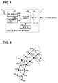
- FIG. 1 is a explanatory diagram showing a construction of a position detection apparatus 1 mounted on a subject vehicle.
- the position detection apparatus 1 includes a GPS (Global Positioning System) receiver 10, an autonomous navigation sensor group 20, a position correction section 30, a road database 40, and an interface (I/F) section 50.
- the position correction section 30 can be also referred to as a position correction apparatus.
- the GPS receiver 10 is constructed similarly to a known GPS receiver.
- the GPS receiver 10 receives a GPS signal transmitted from a GPS satellite via an antenna 11 and extracts a GPS message from the GPS signal.
- the GPS receiver 10 performs a geometric operation to calculate a position coordinate P for the own apparatus based on a pseudo distance and satellite orbit information about multiple (four or more) GPS satellites.
- the position coordinate P is calculated in a three-dimensional coordinate system such as an ENU coordinate system or an ECEF coordinate system.
- the GPS receiver 10 calculates a speed vector V of the own apparatus based on a Doppler shift quantity of a GPS signal.
- a known method is used to calculate the speed vector V based on the Doppler shift quantity of the GPS signal. The following simply describes the method of calculating the speed vector V.
- the method calculates speed vectors of multiple (four or more) GPS satellites from received messages.
- the method further calculates a unit direction vector from the GPS receiver to the GPS satellite.
- the method calculates the speed vector V of the own apparatus based on these pieces of vector information, a carrier frequency of a GPS signal received from each GPS satellite, and a carrier frequency of a GPS signal to be transmitted from each GPS satellite.
- the GPS receiver 10 outputs the calculated speed vector V as well as the position coordinate P of the own apparatus to the position correction section 30.
- the GPS receiver 10 outputs measurement accuracy information as well as the position coordinate P and the speed vector V.
- the measurement accuracy information represents a measurement accuracy ⁇ p of the position coordinate P and a measurement accuracy ⁇ v of the speed vector V calculated based on DOP values.
- the embodiment does not require accurate information about the measurement accuracies ⁇ p and ⁇ v. Any method may be used to calculate the measurement accuracy.
- the measurement accuracy ⁇ p of the position coordinate P can be found from the product of the DOP value and an average difference between measured and estimated distances between each GPS satellite and the GPS receiver.
- the measurement accuracy ⁇ v of the speed vector V can be found from the product of the DOP value and a difference between measured and estimated speeds of the GPS receiver.
- the autonomous navigation sensor group 20 includes multiple autonomous navigation sensors such as a wheel speed sensor, an acceleration sensor, a yaw rate sensor. Outputs from the sensors belonging to the autonomous navigation sensor group 20 are input to the position correction section 30.
- the road database 40 stores road data representing position coordinates of roads in specific regions (e.g., all over Japan).
- the road data may be replaced with link data and node data that are contained in a map database of a known car navigation system and represent road positions and the connection relation between roads.
- the position detection apparatus 1 may be additionally provided with a route guidance function and may be constructed as a car navigation system.
- the interface section 50 communicates with various control ECUs mounted in the vehicle.
- the control ECUs include an engine ECU for engine control, a brake ECU for brake control, and a steering ECU for steering control.
- the interface section 50 supplies the control ECUs with a position coordinate Po of the vehicle detected by the position detection apparatus 1.
- the interface section 50 is constructed as a serial interface or a LAN (CAN communication) interface.
- the interface section 50 supplies the detected position coordinate Po to the control ECUs in the vehicle.
- the position correction section 30 removes a bias error from the position coordinate P of the GPS receiver 10 measured by the GPS receiver 10 and outputs the corrected position coordinate Po outside via the interface section 50.
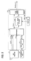
- the position correction section 30 is specifically constructed as shown in FIG. 2.
- FIG. 2 is a block diagram showing a detailed construction of the position correction section 30.
- the position correction section 30 includes an autonomous speed vector calculation section 31, a preprocessing section 33, a bias error estimation section 35, and a bias error removal section 37.
- the autonomous speed vector calculation section 31 is connected to the sensors included in the autonomous navigation sensor group 20. Based on outputs from the sensors, the autonomous speed vector calculation section 31 outputs a displacement magnitude per unit time of the vehicle, namely, a speed vector Vs of the vehicle. The autonomous speed vector calculation section 31 outputs the calculated speed vector Vs of the vehicle to the preprocessing section 33.
- the preprocessing section 33 is connected to the GPS receiver 10 and the autonomous speed vector calculation section 31.
- the preprocessing section 33 corrects the position coordinate P based on the position coordinate P acquired from the GPS receiver 10, the speed vector V, information about the measurement accuracies ⁇ p and ⁇ v, and information about the speed vector Vs acquired from the autonomous speed vector calculation section 31.
- the preprocessing section 33 outputs the corrected position coordinate Pc to the bias error estimation section 35 and the bias error removal section 37.
- FIG. 3 is a flow chart of the positioning accuracy improvement process repeatedly performed by the preprocessing section 33.
- the preprocessing section 33 repeatedly performs the positioning accuracy improvement process at cycle T in synchronization with a measurement cycle T of the GPS receiver 10 and a vector calculation cycle T of the autonomous speed vector calculation section 31.
- the preprocessing section 33 acquires the most recently measured position coordinate P(n) and speed vector V(n) and information about the measurement accuracies ⁇ p(n) and ⁇ v(n) from the GPS receiver 10 (S110). Further, the preprocessing section 33 acquires information about the most recently measured speed vector Vs(n) from the autonomous speed vector calculation section 31 (S120).
- a suffix (n) attached to the parameters P, V, ⁇ p, ⁇ v, and Vs signifies that values for the parameters P, V, ⁇ p, ⁇ v, and Vs are acquired at the most recent cycle.
- a suffix (n-1) signifies that values for the parameters P, V, ⁇ p, ⁇ v, and Vs are acquired at the second most recent cycle.
- ⁇ v
- the preprocessing section 33 proceeds the process to S140 and determines whether or not the variation ⁇ p is greater than an upper bound Mp.
- the upper bound Mp can be preset to a theoretical maximum distance traveled by the vehicle during an elapse of time T at the design stage.
- the preprocessing section 33 When determining that the variation ⁇ p is smaller than or equal to the upper bound Mp (No at S140), the preprocessing section 33 proceeds to S150 by skipping the process at S145. The preprocessing section 33 determines whether or not the variation ⁇ v is greater than the upper bound Mv (S150).
- the upper bound Mv can be preset to a theoretical maximum speed of the vehicle during an elapse of time T at the design stage.
- the preprocessing section 33 proceeds to S160 by skipping the process at S155.
- the preprocessing section 33 follows a built-in coefficient setting map to set coefficients A1, A2, and A3 to values corresponding to measurement accuracies ⁇ p(n) and ⁇ v(n). The preprocessing section 33 then calculates the position coordinate Pc(n) using the following equation based on the previously calculated position coordinate Pc(n-1) (S170).
- Pc ( n ) A ⁇ 1 ⁇ P ( n ) + A ⁇ 2 ⁇ ( Pc ( n - 1 ) + V ( n ) ⁇ T ) + A ⁇ 3 ⁇ Pc ( n - 1 ) + Vs ( n ) ⁇ T
- a parameter T is equivalent to an execution cycle T of the positioning accuracy improvement process.
- a parameter Pc(n) represents a position coordinate Pc of the most recent cycle.
- a parameter Pc(n-k) represents the position coordinate Pc calculated at the kth cycle previous to the most recent cycle.
- the preprocessing section 33 calculates a weighting average between the position coordinate P(n), the position coordinate P(n-1)+V(n) ⁇ T, and the position coordinate P(n-1)+Vs(n) ⁇ T in accordance with the coefficients A1, A2, and A3.
- the position coordinate P(n) is acquired from the GPS receiver 10.
- the position coordinate P(n-1)+V(n) ⁇ T is found based on the speed vector V(n).
- the position coordinate P(n-1)+Vs(n) ⁇ T is found based on an output from the autonomous navigation sensor group 20.
- the preprocessing section 33 Upon completion of calculating the position coordinate Pc(n), the preprocessing section 33 outputs the position coordinate Pc(n) to the bias error estimation section 35 and the bias error removal section 37 (S180). The preprocessing section 33 then terminates the positioning accuracy improvement process.
- the embodiment dynamically configures the coefficients A1, A2, and A3 from the coefficient setting map at S160.
- the coefficients A1, A2, and A3 may be dynamically configured from a predetermined equation.
- an actual equation for configuring the coefficients depends on the method of configuring the measurement accuracies ⁇ p and ⁇ v and is therefore not described here.
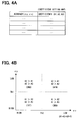
- the embodiment uses the coefficient setting map to configure the coefficients A1, A2, and A3. An example will be described with reference to FIGS. 4A and 4B.
- FIG. 4A is an explanatory diagram showing a configuration of the coefficient setting map.
- FIG. 4B is an explanatory diagram showing a method of configuring the coefficients A1, A2, and A3 marked with the magnitude relation therebetween.
- the preprocessing section 33 determines an area that contains measurement accuracy information ⁇ p(n) and ⁇ v(n) acquired from the GPS receiver 10. The preprocessing section 33 settles values of the coefficients A1, A2, and A3 in accordance with a combination of the coefficients A1, A2, and A3 described in the coefficient setting map associated with the determined area.
- the embodiment assigns threshold values Th1 and Th2 to the measurement accuracies ⁇ p and ⁇ v and four areas to a coordinate space for the measurement accuracies ⁇ p and ⁇ v. That is, a first area is defined so as to satisfy ⁇ p ⁇ Th1 and ⁇ v ⁇ Th2. A second area is defined so as to satisfy ⁇ p ⁇ Th1 and ⁇ v ⁇ Th2. A third area is defined so as to satisfy ⁇ p ⁇ Th1 and ⁇ v ⁇ Th2. A fourth area is defined so as to satisfy ⁇ p ⁇ Th1 and ⁇ v ⁇ Th2. According to the embodiment, decreasing values of the measurement accuracies ⁇ p and ⁇ v increase the accuracy. In other words, larger values of the measurement accuracies ⁇ p and ⁇ v indicate a possibility of larger errors in positions and speeds measured by the GPS receiver 10.
- the first area defines coefficients A1, A2, and A3 so that the coefficient A3 becomes smaller than the coefficients A1 and A2.
- the embodiment configures the coefficients A1, A2, and A3 so as to increase a weight for the position coordinate Pc(n-1) + V(n) ⁇ T found based on the position coordinate P(n) and the speed vector V(n) acquired from the GPS receiver 10.
- the embodiment corrects the position coordinate P(n) and finds the position coordinate Pc(n).
- the second area defines coefficients A1, A2, and A3 so that the coefficient A2 becomes smaller than the coefficients A1 and A3.
- the embodiment configures the coefficients A1, A2, and A3 so as to increase a weight for the position coordinate Pc(n-1) + V(n) ⁇ T found based on the speed vector V(n).
- the embodiment corrects the position coordinate P(n) and finds the position coordinate Pc(n).
- the third area defines coefficients A1, A2, and A3 so that the coefficient A1 becomes larger than the coefficients A2 and A3.
- the embodiment configures the coefficients A1, A2, and A3 so as to increase a weight for the position coordinate P(n) acquired from the GPS receiver 10.
- the embodiment corrects the position coordinate P(n) and finds the position coordinate Pc(n).
- the fourth area defines coefficients A1, A2, and A3 so that the coefficient A3 becomes larger than the coefficients A1 and A2.
- the embodiment configures the coefficients A1, A2, and A3 so as to increase a weight for the position coordinate Pc(n-1) + V(n) ⁇ T found from outputs from the autonomous navigation sensor group 20.
- the embodiment corrects the position coordinate P(n) and finds the position coordinate Pc(n).
- the preprocessing section 33 corrects the position coordinate P(n) acquired from the GPS receiver 10 to acquire the highly accurate position coordinate Pc(n).
- the preprocessing section 33 then outputs the position coordinate Pc(n) to the bias error estimation section 35 and the bias error removal section 37.
- the bias error estimation section 35 acquires the position coordinate Pc output from the preprocessing section 33.
- the bias error estimation section 35 uses the acquired information and road data stored in the road database 40 to estimate a road section traveled by the GPS receiver 10 and estimate a bias error.
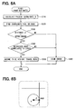
- FIG. 5A is a flow chart showing a bias error estimation process performed by the bias error estimation section 35.
- the bias error estimation section 35 interlocks with the preprocessing section 33 and periodically performs the bias error estimation process in FIG. 5A at cycle T to find a bias error estimate value Y.
- the bias error estimation section 35 acquires the position coordinate Pc(n) from the preprocessing section 33 and records it in a built-in buffer (S210).
- the bias error estimation section 35 recognizes multiple position coordinates ⁇ Pc(n-k)
- the bias error estimation section 35 generates locus data D1 representing a travel locus (or swept path) of the GPS receiver 10 based on the relation between the route length L(k) and the position coordinate Pc(n-k) (S230).
- the bias error estimation section 35 divides a route between the current point Pc(n) and the point Pc(n-K) into M equal route length intervals dL.
- the bias error estimation section 35 uses a linear interpolation technique to find position coordinates Q(1), Q(2), .., and Q(M-1) at the divided points.
- the bias error estimation section 35 Upon completion of generating the locus data D1, the bias error estimation section 35 proceeds to S240 and estimates a vehicle travel road based on the position coordinate Q(0) and road data stored in the road database 40. That is, the bias error estimation section 35 estimates a road traveled by the GPS receiver 10. Specifically, the bias error estimation section 35 performs a road estimation process in FIG. 6A to estimate the vehicle travel road.
- FIG. 6A is a flow chart showing the road estimation process performed by the bias error estimation section 35.
- the bias error estimation section 35 updates the bias error estimate value Y at S290.
- the bias error estimation section 35 uses a predetermined initial value Y0 as the current bias error estimate value Y
- the bias error estimation section 35 searches road data stored in the road database 40 for a road nearest to the position coordinate X, namely a road having a shortest direct distance from the position coordinate X.
- the bias error estimation section 35 determines whether or not the distance ⁇ is smaller than or equal to an upper bound (S330). When determining that the distance ⁇ is smaller than or equal to the upper bound (Yes at S330), the bias error estimation section 35 proceeds to S340. When determining that the distance ⁇ exceeds the upper bound (No at S330), the bias error estimation section 35 proceeds to S360.
- the bias error estimation section 35 determines whether or not the retrieved road nearest to the specified position coordinate X has a planar road configuration (or a road shape in view of upper surface of a road) correlated to the travel locus indicated by the locus data D1 of the GPS receiver 10.
- the bias error estimation section 35 finds a position coordinate R(1) of the point that exits on the road nearest to the position coordinate X specified at S320 and is distanced from the coordinate R(0) by the distance dL equal to the locus data D1 along the road.
- FIG. 7A is an explanatory diagram showing the relation between the position coordinate R(1) and the position coordinate R(0).
- the bias error estimation section 35 calculates an angle ⁇ between the vectors Z1 and Z2.
- ⁇ arccos Z ⁇ 1 ⁇ Z ⁇ 2 /
- FIG. 7B is an explanatory diagram showing a method of setting the vectors Z1 and Z2 and the angle ⁇ between the vectors Z1 and Z2.
- the planar configuration of the specified road is assumed to be similar to the travel locus of the GPS receiver 10.
- the bias error estimation section 35 determines that the road correlates with the travel locus of the GPS receiver 10 (Yes at S340).
- the planar configuration of the specified road is not assumed to be similar to the travel locus of the GPS receiver 10.
- the bias error estimation section 35 determines that the road does not correlate with the travel locus of the GPS receiver 10 (No at S340).
- the bias error estimation section 35 calculates an angle ⁇ a between the vectors Z1 and Za and an angle ⁇ b between the vectors Z1 and Zb.
- the bias error estimation section 35 assumes the determination result to be Yes at S340. Only when both angles ⁇ a and ⁇ b exceed the threshold value ⁇ th, the bias error estimation section 35 assumes the determination result to be No at S340.
- the bias error estimation section 35 discards the coordinate Ra(1) or Rb(1) whichever provides a large angle ⁇ .
- the bias error estimation section 35 determines the position coordinate R(1) using the coordinate Ra(1) or Rb(1) whichever provides a small angle ⁇ .
- the bias error estimation section 35 determines whether or not the specified road correlates with the travel locus of the GPS receiver 10 (S340). When determining that the specified road correlates with the travel locus of the GPS receiver 10 (Yes at S340), the bias error estimation section 35 proceeds to S350 and assumes the specified road to be the vehicle travel road. The bias error estimation section 35 then terminates the road estimation process.
- the bias error estimation section 35 proceeds to S360 and issues an error by determining that any vehicle travel road cannot be estimated correctly. The bias error estimation section 35 then terminates the road estimation process.
- the bias error estimation process estimates the vehicle travel road assuming that the GPS receiver 10 moves along with the vehicle on the road.
- the process estimates a bias error by comparing the vehicle travel road with the travel locus of the GPS receiver 10. Accordingly, the vehicle travel road needs to be estimated correctly at S240.
- the threshold value ⁇ th needs to be set to a value sufficiently smaller than ⁇ /4, for example. Defining the threshold value ⁇ th in this manner can prevent a road crossing the road actually traveled by the vehicle from being assumed to be the vehicle travel road.
- the road estimation process can correctly estimate the vehicle travel road, i.e., the road traveled by the GPS receiver 10.
- the embodiment notifies an error when the distance ⁇ exceeds the upper bound. This is because the specified road is less possibly the vehicle travel road.
- the road estimation process according to the embodiment can solve the problem of inadvertently assuming such a road to be the vehicle travel road.
- the bias error estimation section 35 Upon completion of the road estimation process at S240, the bias error estimation section 35 proceeds to S250 and determines whether or not the road estimation process has estimated the vehicle travel road. Specifically, when the road estimation process issues an error, the bias error estimation section 35 determines No at S250 assuming that the vehicle travel road cannot be estimated. When the road estimation process issues no error and estimates the vehicle travel road, the bias error estimation section 35 determines Yes at S250.
- the bias error estimation section 35 proceeds to S295 and outputs the last updated bias error estimate value Y The bias error estimation section 35 then terminates bias error estimation process.
- the bias error estimation section 35 outputs the predetermined initial value Y0.
- the position coordinates R(0) and R(1) included in the road section data D2 are equivalent to those found in the road estimation process (S240).
- the bias error estimation section 35 finds position coordinates R(2) through R(M) for the points except the already found position coordinates R(0) and R(1) at an interval of distance dL on the road using the point R(0) as the reference point.
- the bias error estimation section 35 describes the position coordinates R(0), R(1), ..., and R(M) to generate the road section data.
- FIG. 8 is an explanatory diagram concerning a method of calculating the weighting average ⁇ .
- ⁇ m 0 M
- ⁇ m 1 ⁇ 0 > ⁇ 1 > ⁇ 2 > ⁇ > ⁇ m > ⁇ > ⁇ M
- the weighting average ⁇ represents a weighting average of errors between the direction components in a vector form.
- the bias error estimation section 35 After calculating the weighting average ⁇ , the bias error estimation section 35 proceeds to S280 and determines whether or not the calculated weighting average E is smaller than or equal to a predetermined upper bound. When determining that the weighting average E is smaller than or equal to the predetermined upper bound (Yes at S280), the bias error estimation section 35 proceeds to S290 and updates the bias error estimate value Y to the weighting average ⁇ calculated at S270 (Y ⁇ ⁇ ). The bias error estimation section 35 outputs the updated bias error estimate value Y to the bias error removal section 37 (S295). The bias error estimation section 35 then terminates the bias error estimation process.
- the bias error estimation section 35 When determining that the weighting average ⁇ exceeds the upper bound (No at S280), the bias error estimation section 35 skips S290 and proceeds to S295 and outputs the bias error estimate value Y to the bias error removal section 37. The bias error estimation section 35 then terminates the bias error estimation process. When the weighting average ⁇ is large and the estimated vehicle travel road is quite possibly incorrect, the bias error estimation section 35 outputs the last updated value as the bias error estimate value Y without updating it.
- the bias error removal section 37 interlocks with the preprocessing section 33 and the bias error estimation section 35.
- the bias error estimation section 35 outputs the bias error estimate value Y Based on the bias error estimate value Y, the bias error removal section 37 removes a bias error from the positioning result Pc(n) input from the preprocessing section 33.
- the position detection apparatus 1 calculates the bias error estimate value Y from the position coordinates Q(0), Q(1), ..., and Q(M) at the measured points and the position coordinates R(0), R(1), ..., and R(M) at the points on the road.
- the position detection apparatus 1 compares the travel locus of the GPS receiver 10 with the road configuration throughout multiple points to estimate a bias error.
- the embodiment defines points at the equal distance interval dL from the position coordinate R(0) to find the position coordinates R(1) through R(M) for the defined points.
- the embodiment finds the position coordinate R(m) on the road corresponding to the position coordinate Q(m) for the points indicated by the locus data D1 in accordance with the positional relation between the points indicated by the locus data D1.
- the embodiment calculates the average ⁇ of errors A(m) at the points as the bias error estimate value Y
- the position detection apparatus 1 can accurately estimate the bias error and accurately remove a bias error component from the positioning result from the GPS receiver 10 to correct the position.
- a conventional technology corrects a positioning result based on the bias error information received from an FM broadcast station.
- the bias error indicated by the received information may greatly deviate from the true value of the bias error at the measuring point.
- the conventional technology cannot properly remove the bias error from the positioning result or accurately correct the positioning result.
- the above-mentioned method can accurately estimate the bias error at the measuring point and can correct the positioning result from the GPS receiver 10 more appropriately than the conventional technology.
- the position detection apparatus 1 need not install an FM receiver in the apparatus and can reduce manufacturing costs for products.
- a map matching technology in a related art compares a positioning result with a road position and forcibly adjusts the positioning result to the position coordinate on the road.
- the related art map matching technology cannot accurately represent a vehicle locus relative to the road or a vehicle movement with reference to the road.
- the embodiment can appropriately correct position coordinates according to the above-mentioned method and solve the problem, i.e., while representing the actual vehicle locus or vehicle movement.
- the vehicle movement can be accurately represented.
- the embodiment calculates the weighting average ⁇ by giving a larger weight to an error at each point in an area where the GPS receiver 10 performs positioning more recently.
- the position detection apparatus 1 can accurately estimate a bias error in proper accordance with changes in the ionization layer.
- the embodiment estimates the vehicle travel road as follows.
- the embodiment stops estimating the vehicle travel road when there is no correlation therebetween. Accordingly, the position detection apparatus 1 according to the embodiment can simply and accurately estimate the vehicle travel road (the road traveled by the GPS receiver 10).
- the embodiment does not estimate the bias error based on the corresponding locus data (No at S250) when the position coordinate X is distant from the nearest road.
- the embodiment corrects the measured position coordinate Pc(n) using the calculated bias error estimate value Y and outputs the corrected position coordinate Po.
- the embodiment can prevent an incorrect position coordinate Po from being calculated and output due to an incorrectly estimated vehicle travel road.
- the embodiment calculates the displacement magnitude Vs of the vehicle based on an output from the autonomous navigation sensor mounted on the vehicle.
- the embodiment corrects the position coordinate P measured by the GPS receiver 10 based on the displacement magnitude Vs.
- the embodiment generates locus data based on the corrected position coordinate Pc. Accordingly, the embodiment can suppress an effect of random errors and appropriately estimate a bias error.
- the road database 40 functions as an example of a road data storage means or device.
- S110 of the process performed by the preprocessing section 33 functions as an example of a position information acquisition means or control unit.
- S210 through S230 of the process performed by the bias error estimation section 35 function as an example of a locus data generation means or control unit.
- S240 and S260 of the process performed by the bias error estimation section 35 function as an example of a road estimation means or control unit.
- S270 and S290 of the process performed by the bias error estimation section 35 function as an example of a bias error estimation means or control unit.
- S120 through S180 of the process performed by the autonomous speed vector calculation section 31 and the preprocessing section 33 function as an example of a preprocessing means or control unit.
- the invention is not limited to the above-mentioned embodiments but may be otherwise variously embodied.
- the embodiment calculates the weighting average E of errors ⁇ (m) as the bias error estimate value Y
- the embodiment corrects the position coordinate P(n) measured by the GPS receiver 10 to the position coordinate Pc(n) and inputs the corrected position coordinate Pc(n) with the improved accuracy to the bias error estimation section 35 and the bias error removal section 37.
- the position detection apparatus 1 may be constructed so as to input the position coordinate P(n) measured by the GPS receiver 10 as is, instead of the position coordinate Pc(n), to the bias error estimation section 35 and the bias error removal section 37.
- the embodiment uses the linear interpolation technique to generate locus data representing the vehicle travel locus at equal distance intervals based on the position coordinate Pc acquired from the GPS receiver 10 via the preprocessing section 33.
- the embodiment generates road section data representing the position coordinate R(m) of the road at equal distance intervals.
- the position coordinate R(m) is equivalent to a position coordinate at a point on the road corresponding to the position coordinate Q(m) for each point indicated by the locus data.
- the embodiment finds a bias error based on these pieces of data. It may be preferable to generate the locus data without the linear interpolation by representing the vehicle travel locus using the position coordinates Pc(n) through Pc(n-K) acquired from the preprocessing section 33.
- Road section data may be generated accordingly.
- a bias error may be found based on these pieces of data. In this manner, it is possible to decrease arithmetic processing loads and reduce the amount of data.
- a software unit e.g., subroutine
- a hardware unit e.g., circuit or integrated circuit
- the hardware unit can be constructed inside of a microcomputer.
- the software unit or any combinations of multiple software units can be included in a software program, which can be contained in a computer-readable storage media or can be downloaded and installed in a computer via a communications network.
- a position correction apparatus includes a bias error estimation means.
- the position correction apparatus estimates a bias error of a position coordinate measured by a GPS receiver and corrects the position coordinate measured by the GPS receiver based on the estimated bias error as follows.
- the position correction apparatus allows a position information acquisition means to acquire a position coordinate measured by the GPS receiver. Based on the position coordinate acquired by the position information acquisition means, the position correction apparatus allows a locus data generation means to generate locus data that represents multiple points of position coordinates for the GPS receiver during a past specified period.
- the position correction apparatus includes a road data storage means that stores road data representing position coordinates of a constructed road.
- the position correction apparatus allows a road estimation means to estimate a road section traveled by the GPS receiver during the past specified period based on the road data and position coordinates acquired by the position information acquisition means.
- the bias error estimation means estimates a bias error based on position coordinates at multiple points in a road section estimated by the road estimation means and position coordinates at multiple points indicated by the locus data for the GPS receiver.
- the position correction apparatus corrects a position coordinate measured by the GPS receiver based on a bias error estimated by the bias error estimation means and outputs the corrected position coordinate (correction output means).
- the position correction apparatus is used to correct a positioning result from the GPS receiver mounted on a movable body such as a vehicle that moves on a road.
- the position correction apparatus estimates a bias error on the assumption that the movable body moves along the road.
- a feature of the position correction apparatus is to estimate a bias error based on the measured position coordinates at points and the position coordinates at points on the road.
- the position correction apparatus can compare the travel locus of the GPS receiver with a road configuration throughout multiple points by estimating a bias error based on the measured position coordinates at points and the position coordinates at points on the road. A bias error can be thus accurately estimated.
- a conventional technology corrects a positioning result based on bias error information received from an FM broadcast station.
- the bias error indicated by the received information greatly deviates from the true value of the bias error at the measuring point, the conventional technology cannot properly remove the bias error from the positioning result or accurately correct the positioning result.
- the above-mentioned method can accurately estimate a bias error at the measuring point.
- the position correction apparatus can more appropriately remove a bias error from the measured position coordinate and more accurately correct the positioning result than the conventional technology.
- the position detection apparatus need not install an FM receiver in the apparatus and can reduce manufacturing costs for products.
- the map matching technology in a related art corrects a positioning result based on road data.
- the related art map matching technology compares a positioning result with a road position and forcibly adjusts the positioning result to the position coordinate on the road. Therefore, the technology necessarily causes the position coordinate of a movable body to overlap with a line representing the road and cannot accurately represent a movable body locus relative to the road or a movable body movement with reference to the road.
- the above-mentioned method can appropriately find a bias error and appropriately correct a positioning result using the found bias error.
- the method can accurately represent the movement of the movable body and correct the position coordinate. Accordingly, applying this technology to vehicle control can detect vehicle movement with reference to a road. The technology can provide accurate control over determining dangerous driving and accordingly assisting a driver in operations.
- the related art technology compares a positioning result with a road position and adjusts the positioning result to the position coordinate on the road. As shown in FIG. 9B , the related art technology cannot make an appropriate correction.
- the correction eliminates movement information relative to the road, making it impossible to accurately represent the vehicle movement. It has been impossible to appropriately provide the control over determining dangerous driving and accordingly assisting a driver in operations based on a positioning result from the GPS receiver and a road configuration.
- the position correction apparatus can accurately estimate a bias error and correct a positioning result.
- the correction does not eliminate information about continuous changes of the position coordinate.
- the position correction apparatus can accurately represent the vehicle movement and accurately control for assisting driver operations.
- the road estimation means can use positional relation between points indicated by the locus data and estimate a position coordinate on the road section corresponding to position coordinates for points indicated by the locus data.
- the bias error estimation means can calculate an error between a position coordinate indicated by the locus data and a position coordinate on the estimated road section corresponding to the position coordinate for each of the position coordinates for points indicated by the locus data and estimate an average of the calculated errors at the points as the bias error.
- a bias error changes more slowly than a random error in terms of the time.
- a position coordinate of the GPS receiver is measured with deviation of a given distance in a given direction from the true position coordinate due to an influence of the bias error.
- points on the road section are configured so that the positional relation between points indicated by the locus data matches a pattern.
- the bias error is estimated from an average of errors in the position coordinate indicated by the locus data at each point and the position coordinate on the road.
- the bias error estimation means may calculate a simple average of errors at the points as an estimate value for the bias error.
- the bias error estimation means may also calculate a weighting average of errors at the points as an estimate value for the bias error.
- the bias error estimation means may be constructed to calculate the weighting average by assigning a larger weight to an error in an area more recently positioned by the GPS receiver.
- the bias error can be accurately estimated in proper accordance with changes in the ionization layer (chronological changes of bias errors).
- the road estimation means may be constructed to use a bias error already estimated by the bias error estimation means and estimates a road section traveled by the GPS receiver during the past specified period.
- a position coordinate acquired from the GPS receiver obviously contains a bias error.
- the position correction apparatus can estimate a road traveled by the GPS receiver by correcting a position coordinate acquired from the GPS receiver using a bias error estimated by the bias error estimation means. In this manner, the position correction apparatus can more accurately estimate a road section traveled by the GPS receiver. As a result, the position correction apparatus can accurately detect the bias error.
- the road estimation means can be constructed to correct a position coordinate indicated by the locus data based on a bias error already estimated by the bias error estimation means, retrieve a road highly correlated with a distribution of points indicated by the locus data based on the corrected position coordinate, and estimate a road section traveled by the GPS receiver on the retrieved road during the past specified period.
- the road estimation means can be constructed to correct a position coordinate for a specific point out of position coordinates for points indicated by the locus data based on bias error already estimated by the bias error estimation means, retrieve a road nearest to the corrected position coordinate, estimate the retrieved nearest road to be the road traveled by the GPS receiver, and estimate a road section traveled by the GPS receiver on the road during the past specified period.
- This technique can simply and accurately estimate the road section traveled by the GPS receiver.
- the following method of estimating a road section is available.
- the method corrects a position coordinate for a specific point out of position coordinates for points indicated by the locus data based on a bias error already estimated by the bias error estimation means.
- the method defines a point nearest from the corrected position coordinate on the road as a reference point.
- the method estimates a position coordinate on the road corresponding to the position coordinate indicated by the locus data at each point so that a distance (road length) along the road from the reference point matches a distance (road length) along a travel locus indicated by the locus data from a specific point.
- the method estimates the position coordinate on the road corresponding to the position coordinate indicated by the locus data.
- the method estimates a section between the estimated position coordinates at both ends of the road to be the road section.
- the position correction apparatus may be constructed to be capable of allowing the bias error estimation means to stop estimating a bias error based on the locus data when a distance between the nearest road retrieved by the road estimation means and the corrected position coordinate at the specified point exceeds a specified upper bound.
- the correction output means may be constructed to correct a certain position coordinate, which is measured by the GPS receiver during a certain period for the bias error estimation means not to estimate a bias error, based on a bias error estimated by the bias error estimation means before the certain period.
- the correction output means may be further constructed to output the corrected certain position coordinate.
- the position correction apparatus can prevent an incorrect road from being estimated as the road traveled by the GPS receiver and prevent an incorrect bias error from being estimated as a result.
- the position correction apparatus may be constructed to include a preprocessing means that calculates a displacement magnitude based on output from an autonomous navigation sensor mounted in the vehicle and corrects a position coordinate acquired by the position information acquisition means based on the displacement magnitude.
- the locus data generation means may be constructed to generate the locus data representing a plurality of points corresponding to position coordinates for the GPS receiver during the past specified period based on a position coordinate corrected by the preprocessing means.
- the position correction apparatus can more accurately find a bias error and appropriately correct a position coordinate measured by the GPS receiver.
Landscapes
- Engineering & Computer Science (AREA)
- Radar, Positioning & Navigation (AREA)
- Remote Sensing (AREA)
- Physics & Mathematics (AREA)
- General Physics & Mathematics (AREA)
- Computer Networks & Wireless Communication (AREA)
- Automation & Control Theory (AREA)
- Navigation (AREA)
- Position Fixing By Use Of Radio Waves (AREA)
- Traffic Control Systems (AREA)
Applications Claiming Priority (1)
| Application Number | Priority Date | Filing Date | Title |
|---|---|---|---|
| JP2007205487A JP4453728B2 (ja) | 2007-08-07 | 2007-08-07 | 位置補正装置 |
Publications (3)
| Publication Number | Publication Date |
|---|---|
| EP2023084A2 true EP2023084A2 (de) | 2009-02-11 |
| EP2023084A3 EP2023084A3 (de) | 2010-12-01 |
| EP2023084B1 EP2023084B1 (de) | 2011-12-28 |
Family
ID=39971083
Family Applications (1)
| Application Number | Title | Priority Date | Filing Date |
|---|---|---|---|
| EP08012334A Ceased EP2023084B1 (de) | 2007-08-07 | 2008-07-08 | Positionskorrekturvorrichtung |
Country Status (4)
| Country | Link |
|---|---|
| US (1) | US8073619B2 (de) |
| EP (1) | EP2023084B1 (de) |
| JP (1) | JP4453728B2 (de) |
| CN (1) | CN101363740B (de) |
Cited By (6)
| Publication number | Priority date | Publication date | Assignee | Title |
|---|---|---|---|---|
| EP2462404A4 (de) * | 2009-08-03 | 2013-10-30 | Tomtom North America Inc | Verfahren zur vorverarbeitung von sondendaten |
| EP2717014A4 (de) * | 2011-05-10 | 2014-10-29 | Seiko Epson Corp | Positionsberechnungsverfahren und positionsberechnungsvorrichtung |
| EP2825902A4 (de) * | 2012-03-12 | 2015-10-21 | Strava Inc | Reparatur von gps-daten |
| CN106679680A (zh) * | 2015-11-11 | 2017-05-17 | 阿尔派株式会社 | 导航装置及其地图显示方法 |
| EP3226034A1 (de) * | 2016-04-01 | 2017-10-04 | Centre National d'Etudes Spatiales | Verbesserter gnss-empfänger mit geschwindigkeitsintegration |
| CN109917440A (zh) * | 2019-04-09 | 2019-06-21 | 广州小鹏汽车科技有限公司 | 一种组合导航方法、系统及车辆 |
Families Citing this family (36)
| Publication number | Priority date | Publication date | Assignee | Title |
|---|---|---|---|---|
| JP5566039B2 (ja) * | 2009-03-13 | 2014-08-06 | 富士通株式会社 | 測位装置 |
| JP5609073B2 (ja) * | 2009-06-16 | 2014-10-22 | カシオ計算機株式会社 | 測位装置、測位方法およびプログラム |
| JP5673071B2 (ja) * | 2010-03-10 | 2015-02-18 | 株式会社豊田中央研究所 | 位置推定装置及びプログラム |
| US9273968B2 (en) | 2010-06-23 | 2016-03-01 | Aisin Aw Co., Ltd. | Track information generating device, track information generating method, and computer-readable storage medium |
| TWI417520B (zh) * | 2010-08-19 | 2013-12-01 | Hon Hai Prec Ind Co Ltd | 電子裝置及其gps誤差偵測方法 |
| US9664518B2 (en) | 2010-08-27 | 2017-05-30 | Strava, Inc. | Method and system for comparing performance statistics with respect to location |
| JP5639874B2 (ja) * | 2010-12-24 | 2014-12-10 | 株式会社日立製作所 | 運転支援装置 |
| US9291713B2 (en) | 2011-03-31 | 2016-03-22 | Strava, Inc. | Providing real-time segment performance information |
| US9116922B2 (en) | 2011-03-31 | 2015-08-25 | Strava, Inc. | Defining and matching segments |
| US8543320B2 (en) * | 2011-05-19 | 2013-09-24 | Microsoft Corporation | Inferring a behavioral state of a vehicle |
| US20130155102A1 (en) * | 2011-12-20 | 2013-06-20 | Honeywell International Inc. | Systems and methods of accuracy mapping in a location tracking system |
| CN103207402B (zh) * | 2012-01-13 | 2015-04-15 | 昆达电脑科技(昆山)有限公司 | 导航轨迹推估系统及其推估方法 |
| DE102012213754A1 (de) * | 2012-08-03 | 2014-02-06 | Robert Bosch Gmbh | Verfahren und Informationssystem zum Abgleichen eines Sensorsignals eines Sensors in einem Fahrzeug |
| JP5895815B2 (ja) * | 2012-10-30 | 2016-03-30 | トヨタ自動車株式会社 | 残距離算出装置、残距離算出方法及び運転支援装置 |
| CN103809195B (zh) * | 2014-02-13 | 2016-05-25 | 大豪信息技术(威海)有限公司 | 一种gps轨迹曲线的生成方法及装置 |
| CN105338541B (zh) * | 2014-06-30 | 2018-11-13 | 华为技术有限公司 | 一种基于移动无线网络数据的异常轨迹检测方法及装置 |
| CN105759289A (zh) * | 2014-12-15 | 2016-07-13 | 国际商业机器公司 | 用于处理gps漂移的方法和系统 |
| JP6520597B2 (ja) | 2015-09-16 | 2019-05-29 | 株式会社デンソー | 車両位置補正装置 |
| DE102016222272B4 (de) * | 2016-11-14 | 2018-05-30 | Volkswagen Aktiengesellschaft | Schätzen einer Eigenposition |
| DE102017211605A1 (de) * | 2017-07-07 | 2019-01-10 | Robert Bosch Gmbh | Verfahren zur Lokalisierung eines höher automatisierten Fahrzeugs (HAF), insbesondere eines hochautomatisierten Fahrzeugs, und ein Fahrerassistenzsystem |
| JP7069624B2 (ja) * | 2017-10-05 | 2022-05-18 | 日産自動車株式会社 | 位置演算方法、車両制御方法及び位置演算装置 |
| CN107907894A (zh) * | 2017-11-09 | 2018-04-13 | 上汽通用五菱汽车股份有限公司 | 无人驾驶汽车定位方法、装置、存储介质及无人驾驶汽车 |
| US10921133B2 (en) * | 2017-12-07 | 2021-02-16 | International Business Machines Corporation | Location calibration based on movement path and map objects |
| CN108413945B (zh) * | 2017-12-25 | 2020-11-06 | 中国神华能源股份有限公司 | 轨道坐标点经纬高测量装置及方法 |
| DE102018205430A1 (de) * | 2018-04-11 | 2019-10-17 | Robert Bosch Gmbh | Verfahren zur satellitengestützten Ermittlung einer Fahrzeugposition |
| JP7238356B2 (ja) * | 2018-11-16 | 2023-03-14 | 株式会社アイシン | 車両制御装置および車両制御プログラム |
| CN109507699B (zh) * | 2018-12-03 | 2021-05-28 | 江苏本能科技有限公司 | 车用卫星定位校正方法及装置 |
| CN111765901B (zh) * | 2019-04-02 | 2022-05-31 | 北京三快在线科技有限公司 | 路径规划质量评估方法和装置,存储介质和电子设备 |
| DE102019208872A1 (de) * | 2019-06-18 | 2020-12-24 | Continental Teves Ag & Co. Ohg | Verfahren zur Fehlerbewertung bei einer Positionsbestimmung |
| CN112445879A (zh) * | 2019-09-04 | 2021-03-05 | 阿里巴巴集团控股有限公司 | 轨迹数据处理方法及装置、介质、终端、服务器 |
| CN110906830B (zh) * | 2019-12-17 | 2022-02-11 | 美国西北仪器公司 | 智能测距轮系统及其测距方法 |
| CN110926484B (zh) * | 2020-02-10 | 2020-05-19 | 中智行科技有限公司 | 车辆位置的获取方法、装置以及智能车辆 |
| DE102020212028A1 (de) * | 2020-09-24 | 2022-03-24 | Robert Bosch Gesellschaft mit beschränkter Haftung | Verfahren zur Bestimmung von Navigationsdaten |
| CN112240770A (zh) * | 2020-10-15 | 2021-01-19 | 浙江欣奕华智能科技有限公司 | 一种生成机器人运动轨迹的方法、装置及终端 |
| CN114740505B (zh) * | 2021-01-08 | 2025-05-16 | 腾讯科技(深圳)有限公司 | 一种定位处理方法及装置 |
| US20220219719A1 (en) * | 2021-01-13 | 2022-07-14 | James Stracka | Methods and systems for locating a dynamic object in a field of known static objects |
Citations (2)
| Publication number | Priority date | Publication date | Assignee | Title |
|---|---|---|---|---|
| EP0522862A1 (de) | 1991-07-10 | 1993-01-13 | Pioneer Electronic Corporation | GPS-Navigationssystem mit selektiver Positions-Offset-Korrektur |
| US6502033B1 (en) | 2000-10-05 | 2002-12-31 | Navigation Technologies Corp. | Turn detection algorithm for vehicle positioning |
Family Cites Families (20)
| Publication number | Priority date | Publication date | Assignee | Title |
|---|---|---|---|---|
| JPH0823578B2 (ja) | 1987-10-21 | 1996-03-06 | 松下電器産業株式会社 | 車載用ナビゲータ |
| JPH02187899A (ja) | 1989-01-13 | 1990-07-24 | Matsushita Electric Ind Co Ltd | バス到着予定時刻の提供方法 |
| US5416477A (en) * | 1990-11-06 | 1995-05-16 | Matsushita Electric Industrial Co., Ltd. | Navigation system mounted on vehicle |
| JP2734195B2 (ja) | 1990-11-06 | 1998-03-30 | 松下電器産業株式会社 | 車載用ナビゲーション装置 |
| JPH064024A (ja) | 1992-06-23 | 1994-01-14 | Japan Radio Co Ltd | 車載ナビゲーション装置 |
| US6023653A (en) * | 1995-11-30 | 2000-02-08 | Fujitsu Ten Limited | Vehicle position detecting apparatus |
| KR100267543B1 (ko) * | 1996-04-28 | 2000-10-16 | 모리 하루오 | 도로정보 또는 교차점정보의 처리장치 |
| JP2861957B2 (ja) * | 1996-07-31 | 1999-02-24 | トヨタ自動車株式会社 | 測位システム及びこのシステムに用いられる固定局側装置及び測位装置 |
| JP3295009B2 (ja) | 1996-12-24 | 2002-06-24 | 富士通テン株式会社 | 車両位置補正装置 |
| JP3243236B2 (ja) * | 1999-09-24 | 2002-01-07 | 松下電器産業株式会社 | 位置データ間引き装置 |
| US6405124B1 (en) * | 2000-05-31 | 2002-06-11 | Lockheed Martin Corporation | System and method for offset course guidance |
| JP2002040128A (ja) | 2000-07-26 | 2002-02-06 | Sony Corp | Gpsによる測位方法、ナビゲーション装置およびgps受信装置 |
| US6581005B2 (en) * | 2000-11-30 | 2003-06-17 | Nissan Motor Co., Ltd. | Vehicle position calculation apparatus and method |
| US6597987B1 (en) * | 2001-05-15 | 2003-07-22 | Navigation Technologies Corp. | Method for improving vehicle positioning in a navigation system |
| US6615135B2 (en) * | 2001-05-24 | 2003-09-02 | Prc Inc. | Satellite based on-board vehicle navigation system including predictive filtering and map-matching to reduce errors in a vehicular position |
| KR20040099353A (ko) * | 2002-03-28 | 2004-11-26 | 마쯔시다덴기산교 가부시키가이샤 | 상대 위치 정보 보정 장치, 상대 위치 정보 보정 방법,상대 위치 정보 보정 프로그램, 형상벡터 생성 장치,형상벡터 생성 방법 및 형상벡터 생성 프로그램 |
| FI113092B (fi) * | 2002-05-31 | 2004-02-27 | Ekahau Oy | Paikannusepävarmuuden mittauksia ja niiden sovelluksia |
| JP3960243B2 (ja) | 2003-03-25 | 2007-08-15 | 住友電気工業株式会社 | リンク旅行時間推定方法及び装置 |
| EP1500907B1 (de) * | 2003-07-21 | 2014-11-12 | LG Electronics, Inc. | Gerät und Verfahren zum Detektieren einer Fahrzeugposition in einem Navigationssystem |
| US7809500B2 (en) * | 2005-02-07 | 2010-10-05 | Microsoft Corporation | Resolving discrepancies between location information and route data on a navigation device |
-
2007
- 2007-08-07 JP JP2007205487A patent/JP4453728B2/ja not_active Expired - Fee Related
-
2008
- 2008-07-08 EP EP08012334A patent/EP2023084B1/de not_active Ceased
- 2008-08-04 US US12/221,673 patent/US8073619B2/en not_active Expired - Fee Related
- 2008-08-05 CN CN200810131265XA patent/CN101363740B/zh not_active Expired - Fee Related
Patent Citations (2)
| Publication number | Priority date | Publication date | Assignee | Title |
|---|---|---|---|---|
| EP0522862A1 (de) | 1991-07-10 | 1993-01-13 | Pioneer Electronic Corporation | GPS-Navigationssystem mit selektiver Positions-Offset-Korrektur |
| US6502033B1 (en) | 2000-10-05 | 2002-12-31 | Navigation Technologies Corp. | Turn detection algorithm for vehicle positioning |
Cited By (10)
| Publication number | Priority date | Publication date | Assignee | Title |
|---|---|---|---|---|
| EP2462404A4 (de) * | 2009-08-03 | 2013-10-30 | Tomtom North America Inc | Verfahren zur vorverarbeitung von sondendaten |
| US9097542B2 (en) | 2009-08-03 | 2015-08-04 | Tomtom North America, Inc. | Methods of pre-processing probe data |
| EP2717014A4 (de) * | 2011-05-10 | 2014-10-29 | Seiko Epson Corp | Positionsberechnungsverfahren und positionsberechnungsvorrichtung |
| US9026362B2 (en) | 2011-05-10 | 2015-05-05 | Seiko Epson Corporation | Position calculating method and position calculating device |
| EP2825902A4 (de) * | 2012-03-12 | 2015-10-21 | Strava Inc | Reparatur von gps-daten |
| CN106679680A (zh) * | 2015-11-11 | 2017-05-17 | 阿尔派株式会社 | 导航装置及其地图显示方法 |
| EP3226034A1 (de) * | 2016-04-01 | 2017-10-04 | Centre National d'Etudes Spatiales | Verbesserter gnss-empfänger mit geschwindigkeitsintegration |
| WO2017167791A1 (en) * | 2016-04-01 | 2017-10-05 | Centre National D'etudes Spatiales | Improved gnss receiver using velocity integration |
| US10942281B2 (en) | 2016-04-01 | 2021-03-09 | Centre National D'etudes Spatiales | GNSS receiver using a combination of velocity integration and precise point positioning |
| CN109917440A (zh) * | 2019-04-09 | 2019-06-21 | 广州小鹏汽车科技有限公司 | 一种组合导航方法、系统及车辆 |
Also Published As
| Publication number | Publication date |
|---|---|
| JP2009041988A (ja) | 2009-02-26 |
| EP2023084B1 (de) | 2011-12-28 |
| JP4453728B2 (ja) | 2010-04-21 |
| CN101363740A (zh) | 2009-02-11 |
| US20090043495A1 (en) | 2009-02-12 |
| EP2023084A3 (de) | 2010-12-01 |
| US8073619B2 (en) | 2011-12-06 |
| CN101363740B (zh) | 2011-02-09 |
Similar Documents
| Publication | Publication Date | Title |
|---|---|---|
| EP2023084B1 (de) | Positionskorrekturvorrichtung | |
| EP2045577B1 (de) | Positionierungsvorrichtung und navigationssystem | |
| US10422658B2 (en) | Method, fusion filter, and system for fusing sensor signals with different temporal signal output delays into a fusion data set | |
| EP1457946B1 (de) | Vorrichtung und Verfahren zur Bestimmung der Position eines Mobilkörpers in einem Navigationssystem | |
| EP2664894B1 (de) | Navigationsvorrichtung | |
| EP1818682B1 (de) | Positionsberechnungsgerät | |
| US6675074B2 (en) | Method and system for vehicle trajectory estimation | |
| US6381536B1 (en) | Apparatus for generating road information from stored digital map database | |
| EP2657920B1 (de) | Fahrassistenzvorrichtung | |
| US11079494B2 (en) | Positioning device | |
| JP5273213B2 (ja) | 走行支援システム及び車両用無線通信装置 | |
| US9057615B2 (en) | Systems and methods for navigating using corrected yaw bias values | |
| EP3312634B1 (de) | Positionierungsvorrichtung | |
| JP2008215917A (ja) | 位置検出装置および位置検出方法 | |
| CN106687764A (zh) | 用于初始化传感器融合系统的方法和系统 | |
| US12215976B2 (en) | Estimation device, estimation method, program product for estimation | |
| US8401787B2 (en) | Method of determining drive lane using steering wheel model | |
| JP2016218015A (ja) | 車載センサ補正装置、自己位置推定装置、プログラム | |
| US11409006B2 (en) | Azimuth estimation device | |
| JP3569015B2 (ja) | Gpsナビゲーション装置 | |
| US6473689B1 (en) | Method for navigating a vehicle | |
| KR20130057114A (ko) | 학습을 이용한 자립 항법 시스템 및 그 방법 | |
| JPH07280926A (ja) | 車両用ナビゲーション装置 |
Legal Events
| Date | Code | Title | Description |
|---|---|---|---|
| PUAI | Public reference made under article 153(3) epc to a published international application that has entered the european phase |
Free format text: ORIGINAL CODE: 0009012 |
|
| AK | Designated contracting states |
Kind code of ref document: A2 Designated state(s): AT BE BG CH CY CZ DE DK EE ES FI FR GB GR HR HU IE IS IT LI LT LU LV MC MT NL NO PL PT RO SE SI SK TR |
|
| AX | Request for extension of the european patent |
Extension state: AL BA MK RS |
|
| PUAL | Search report despatched |
Free format text: ORIGINAL CODE: 0009013 |
|
| AK | Designated contracting states |
Kind code of ref document: A3 Designated state(s): AT BE BG CH CY CZ DE DK EE ES FI FR GB GR HR HU IE IS IT LI LT LU LV MC MT NL NO PL PT RO SE SI SK TR |
|
| AX | Request for extension of the european patent |
Extension state: AL BA MK RS |
|
| 17P | Request for examination filed |
Effective date: 20110222 |
|
| RIC1 | Information provided on ipc code assigned before grant |
Ipc: G01C 21/30 20060101AFI20110504BHEP |
|
| GRAP | Despatch of communication of intention to grant a patent |
Free format text: ORIGINAL CODE: EPIDOSNIGR1 |
|
| RIN1 | Information on inventor provided before grant (corrected) |
Inventor name: KATO, YOSHIFUMI Inventor name: INOU, HIROSHI Inventor name: GOTO, MASAHIRO Inventor name: HATTORI, YOUSUKE Inventor name: OKADA, MINORU |
|
| AKX | Designation fees paid |
Designated state(s): DE FR |
|
| GRAS | Grant fee paid |
Free format text: ORIGINAL CODE: EPIDOSNIGR3 |
|
| GRAA | (expected) grant |
Free format text: ORIGINAL CODE: 0009210 |
|
| AK | Designated contracting states |
Kind code of ref document: B1 Designated state(s): DE FR |
|
| REG | Reference to a national code |
Ref country code: DE Ref legal event code: R096 Ref document number: 602008012278 Country of ref document: DE Effective date: 20120308 |
|
| REG | Reference to a national code |
Ref country code: DE Ref legal event code: R084 Ref document number: 602008012278 Country of ref document: DE Effective date: 20120807 |
|
| PLBE | No opposition filed within time limit |
Free format text: ORIGINAL CODE: 0009261 |
|
| STAA | Information on the status of an ep patent application or granted ep patent |
Free format text: STATUS: NO OPPOSITION FILED WITHIN TIME LIMIT |
|
| 26N | No opposition filed |
Effective date: 20121001 |
|
| REG | Reference to a national code |
Ref country code: DE Ref legal event code: R097 Ref document number: 602008012278 Country of ref document: DE Effective date: 20121001 |
|
| REG | Reference to a national code |
Ref country code: FR Ref legal event code: PLFP Year of fee payment: 8 |
|
| REG | Reference to a national code |
Ref country code: FR Ref legal event code: PLFP Year of fee payment: 9 |
|
| REG | Reference to a national code |
Ref country code: FR Ref legal event code: PLFP Year of fee payment: 10 |
|
| REG | Reference to a national code |
Ref country code: FR Ref legal event code: PLFP Year of fee payment: 11 |
|
| PGFP | Annual fee paid to national office [announced via postgrant information from national office to epo] |
Ref country code: FR Payment date: 20180725 Year of fee payment: 11 Ref country code: DE Payment date: 20180723 Year of fee payment: 11 |
|
| REG | Reference to a national code |
Ref country code: DE Ref legal event code: R119 Ref document number: 602008012278 Country of ref document: DE |
|
| PG25 | Lapsed in a contracting state [announced via postgrant information from national office to epo] |
Ref country code: DE Free format text: LAPSE BECAUSE OF NON-PAYMENT OF DUE FEES Effective date: 20200201 |
|
| PG25 | Lapsed in a contracting state [announced via postgrant information from national office to epo] |
Ref country code: FR Free format text: LAPSE BECAUSE OF NON-PAYMENT OF DUE FEES Effective date: 20190731 |