EP2020925B1 - Release mechanisms for a clip device - Google Patents
Release mechanisms for a clip device Download PDFInfo
- Publication number
- EP2020925B1 EP2020925B1 EP07777322.4A EP07777322A EP2020925B1 EP 2020925 B1 EP2020925 B1 EP 2020925B1 EP 07777322 A EP07777322 A EP 07777322A EP 2020925 B1 EP2020925 B1 EP 2020925B1
- Authority
- EP
- European Patent Office
- Prior art keywords
- retainer
- clip
- arms
- sliding ring
- distal
- Prior art date
- Legal status (The legal status is an assumption and is not a legal conclusion. Google has not performed a legal analysis and makes no representation as to the accuracy of the status listed.)
- Not-in-force
Links
- 230000007246 mechanism Effects 0.000 title description 17
- 238000000034 method Methods 0.000 claims description 13
- 239000012858 resilient material Substances 0.000 claims description 3
- 239000012530 fluid Substances 0.000 description 10
- 238000011010 flushing procedure Methods 0.000 description 9
- 230000023597 hemostasis Effects 0.000 description 8
- 230000008878 coupling Effects 0.000 description 5
- 238000010168 coupling process Methods 0.000 description 5
- 238000005859 coupling reaction Methods 0.000 description 5
- 210000004369 blood Anatomy 0.000 description 4
- 239000008280 blood Substances 0.000 description 4
- 210000001124 body fluid Anatomy 0.000 description 4
- 230000000295 complement effect Effects 0.000 description 4
- 230000002439 hemostatic effect Effects 0.000 description 4
- 208000032843 Hemorrhage Diseases 0.000 description 3
- 230000000740 bleeding effect Effects 0.000 description 3
- 230000000694 effects Effects 0.000 description 3
- 238000002347 injection Methods 0.000 description 3
- 239000007924 injection Substances 0.000 description 3
- 230000013011 mating Effects 0.000 description 3
- 208000012671 Gastrointestinal haemorrhages Diseases 0.000 description 2
- 238000013459 approach Methods 0.000 description 2
- 238000005452 bending Methods 0.000 description 2
- 210000004204 blood vessel Anatomy 0.000 description 2
- 238000004891 communication Methods 0.000 description 2
- 208000030304 gastrointestinal bleeding Diseases 0.000 description 2
- 230000002401 inhibitory effect Effects 0.000 description 2
- 229910001220 stainless steel Inorganic materials 0.000 description 2
- 239000010935 stainless steel Substances 0.000 description 2
- 238000001356 surgical procedure Methods 0.000 description 2
- 230000007704 transition Effects 0.000 description 2
- 238000006424 Flood reaction Methods 0.000 description 1
- 208000008469 Peptic Ulcer Diseases 0.000 description 1
- FAPWRFPIFSIZLT-UHFFFAOYSA-M Sodium chloride Chemical compound [Na+].[Cl-] FAPWRFPIFSIZLT-UHFFFAOYSA-M 0.000 description 1
- 206010046996 Varicose vein Diseases 0.000 description 1
- 210000003484 anatomy Anatomy 0.000 description 1
- 239000011324 bead Substances 0.000 description 1
- 230000017531 blood circulation Effects 0.000 description 1
- 230000006835 compression Effects 0.000 description 1
- 238000007906 compression Methods 0.000 description 1
- 238000013461 design Methods 0.000 description 1
- 238000011161 development Methods 0.000 description 1
- 230000002496 gastric effect Effects 0.000 description 1
- 210000001035 gastrointestinal tract Anatomy 0.000 description 1
- 230000003902 lesion Effects 0.000 description 1
- 238000004519 manufacturing process Methods 0.000 description 1
- 239000000463 material Substances 0.000 description 1
- 239000007769 metal material Substances 0.000 description 1
- HLXZNVUGXRDIFK-UHFFFAOYSA-N nickel titanium Chemical compound [Ti].[Ti].[Ti].[Ti].[Ti].[Ti].[Ti].[Ti].[Ti].[Ti].[Ti].[Ni].[Ni].[Ni].[Ni].[Ni].[Ni].[Ni].[Ni].[Ni].[Ni].[Ni].[Ni].[Ni].[Ni] HLXZNVUGXRDIFK-UHFFFAOYSA-N 0.000 description 1
- 229910001000 nickel titanium Inorganic materials 0.000 description 1
- 239000003229 sclerosing agent Substances 0.000 description 1
- 239000011780 sodium chloride Substances 0.000 description 1
- 239000000243 solution Substances 0.000 description 1
- 230000001225 therapeutic effect Effects 0.000 description 1
- 230000000659 thermocoagulation Effects 0.000 description 1
- 208000027185 varicose disease Diseases 0.000 description 1
Images


Classifications
-
- A—HUMAN NECESSITIES
- A61—MEDICAL OR VETERINARY SCIENCE; HYGIENE
- A61B—DIAGNOSIS; SURGERY; IDENTIFICATION
- A61B17/00—Surgical instruments, devices or methods, e.g. tourniquets
- A61B17/12—Surgical instruments, devices or methods, e.g. tourniquets for ligaturing or otherwise compressing tubular parts of the body, e.g. blood vessels, umbilical cord
- A61B17/122—Clamps or clips, e.g. for the umbilical cord
-
- A—HUMAN NECESSITIES
- A61—MEDICAL OR VETERINARY SCIENCE; HYGIENE
- A61B—DIAGNOSIS; SURGERY; IDENTIFICATION
- A61B17/00—Surgical instruments, devices or methods, e.g. tourniquets
- A61B17/12—Surgical instruments, devices or methods, e.g. tourniquets for ligaturing or otherwise compressing tubular parts of the body, e.g. blood vessels, umbilical cord
- A61B17/128—Surgical instruments, devices or methods, e.g. tourniquets for ligaturing or otherwise compressing tubular parts of the body, e.g. blood vessels, umbilical cord for applying or removing clamps or clips
- A61B17/1285—Surgical instruments, devices or methods, e.g. tourniquets for ligaturing or otherwise compressing tubular parts of the body, e.g. blood vessels, umbilical cord for applying or removing clamps or clips for minimally invasive surgery
-
- A—HUMAN NECESSITIES
- A61—MEDICAL OR VETERINARY SCIENCE; HYGIENE
- A61B—DIAGNOSIS; SURGERY; IDENTIFICATION
- A61B17/00—Surgical instruments, devices or methods, e.g. tourniquets
- A61B17/064—Surgical staples, i.e. penetrating the tissue
- A61B17/0643—Surgical staples, i.e. penetrating the tissue with separate closing member, e.g. for interlocking with staple
-
- A—HUMAN NECESSITIES
- A61—MEDICAL OR VETERINARY SCIENCE; HYGIENE
- A61B—DIAGNOSIS; SURGERY; IDENTIFICATION
- A61B17/00—Surgical instruments, devices or methods, e.g. tourniquets
- A61B2017/00526—Methods of manufacturing
- A61B2017/0053—Loading magazines or sutures into applying tools
-
- A—HUMAN NECESSITIES
- A61—MEDICAL OR VETERINARY SCIENCE; HYGIENE
- A61B—DIAGNOSIS; SURGERY; IDENTIFICATION
- A61B17/00—Surgical instruments, devices or methods, e.g. tourniquets
- A61B17/064—Surgical staples, i.e. penetrating the tissue
- A61B2017/0641—Surgical staples, i.e. penetrating the tissue having at least three legs as part of one single body
-
- A—HUMAN NECESSITIES
- A61—MEDICAL OR VETERINARY SCIENCE; HYGIENE
- A61B—DIAGNOSIS; SURGERY; IDENTIFICATION
- A61B90/00—Instruments, implements or accessories specially adapted for surgery or diagnosis and not covered by any of the groups A61B1/00 - A61B50/00, e.g. for luxation treatment or for protecting wound edges
- A61B90/03—Automatic limiting or abutting means, e.g. for safety
- A61B2090/033—Abutting means, stops, e.g. abutting on tissue or skin
Definitions
- the present invention relates to a clip, and more specifically, to a clip that can be used to cause hemostasis of blood vessels along the gastrointestinal tract, or that can be used as an endoscopic tool for holding tissue or the like.
- a clip may be introduced into a body cavity through an endoscope to grasp living tissue of a body cavity for hemostasis, marking, and/or ligating.
- clips are now being used in a number of applications related to gastrointestinal bleeding such as peptic ulcers, Mallory-Weiss tears, Dieulafoy's lesions, angiomas, post-papillotomy bleeding, and small varices with active bleeding.
- Gastrointestinal bleeding is a somewhat common and serious condition that is often fatal if left untreated. This problem has prompted the development of a number of endoscopic therapeutic approaches to achieve hemostasis such as the injection of sclerosing agents and contact thermo-coagulation techniques. Although such approaches are often effective, bleeding continues for many patients and corrective surgery therefore becomes necessary. Because surgery is an invasive technique that is associated with a high morbidity rate and many other undesirable side effects, there exists a need for highly effective, less invasive procedures.
- Another problem often encountered with conventional hemostatic devices is the difficulty in securing the clip device to the delivery apparatus prior to reaching the target area within the patient, and then quickly and easily releasing the clip device from the delivery apparatus once the clip has been attached to the target site.
- a clip device for living tissue in a body cavity comprises an outer sheath that is insertable into the body cavity. Disposed within the outer sheath is an inner sheath. The inner sheath is independently slidable within the outer sheath.
- a clip is provided with a proximal end from which at least two arms extend. The arms are formed of a resilient material and are shaped such that the arms are biased or have a tendency to be in an open position.
- a first retainer is attached to the proximal end of the clip.
- An operating wire is slidably disposed within an inner portion of the inner sheath, and has a distal end portion with a second retainer attached to the distal end thereof.
- the second retainer releasably mates with the first retainer to couple the clip to the operating wire.
- a sliding ring is provided and is configured such that when the sliding ring is moved over the arms it holds them in a closed position.
- the sliding ring has a portion that is sized to contact the inner sheath so that when the inner sheath is advanced, the sliding ring slides over the arms of the clip to close them.
- the two retainers are joined together and the sliding ring is moved to a position such that the sliding ring covers the two retainers.
- the clip is joined with the operating wire.
- the outer sheath is advanced to a position over the clip to compress or collapse the arms within the device so that it may be passed into a channel of an endoscope.
- the outer sheath is retracted to expose the arms, causing them to open radially outward.
- the inner sheath is advanced, pushing the sliding ring over the arms so as to close the arms onto the tissue. Thereafter, when the inner sheath is retracted, the retainers may be released, the device is retracted, and the clip and first retainer are left behind.
- stop elements such as beads, may be disposed on the clip to ensure that the sliding ring is not advanced distally beyond the end of the clip. Further, the stop elements may lockingly engage with the sliding ring to ensure that the sliding ring does not disengage from the clip.
- the first retainer may be disengaged from the second retainer, for example, by retracting the second retainer with respect to the first retainer, rotating the second retainer with respect to the first retainer, or simply removing the sliding ring or inner sheath so that they no longer radially restrain the retainers.
- an alternative clip comprising at least two arms having substantially flat regions along part or all of their length.
- the proximal ends of the arms unite at the proximal end of the clip.
- the proximal end of the clip has a hole formed therein.
- Various means are disclosed for coupling an operating wire to the clip using the hole at the proximal end of the clip.
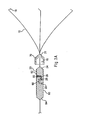
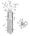
- FIG. 1 is an illustration of one embodiment of a clip device according to the present invention.
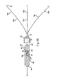
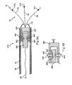
- FIG. 2 is a partial side-sectional view of a portion of the clip device of FIG. 1 before the retainers are joined.
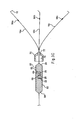
- FIG. 3A is a side-sectional view of a portion of the clip device of FIG. 1 after the retainers are joined.
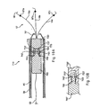
- FIG. 3B is a side-sectional view of an alternative clip device of FIGS. 1-3A .
- FIG. 3C is a side-sectional view of a further alternative clip device of FIGS. 1-3A .
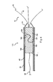
- FIG. 4 is a side-sectional view of an alternative release mechanism that may be used to deploy a clip device.
- FIGS. 5A-5C are, respectively, a side-sectional view of an alternative release mechanism that may be used to deploy a clip device, a side-sectional view of the first retainer of FIG. 5A after deployment, and a side-sectional view of a further alternative release mechanism.
- FIG. 6 is a side view of an alternative release mechanism that may be used to deploy a clip device.
- FIGS. 7A-7B are, respectively, a side-sectional view of an alternative release mechanism that may be used to deploy a clip device, and an end view showing the distal end of the sliding ring of FIG. 7A .
- FIG. 8 is a side-sectional view of an alternative release mechanism that may be used to deploy a clip device.
- FIGS. 9A-9B are side-sectional views of alternative release mechanisms that may be used to deploy a clip device.
- FIGS. 10A-10B are side-sectional views of alternative release mechanisms that may be used to deploy a clip device.
- FIGS. 11A-11B are, respectively, a side-sectional view of an alternative release mechanism that may be used to deploy a clip device, and a side view of the inner sheath and sliding ring of FIG. 11A .
- FIG. 12 is a side view of an alternative release mechanism that may be used to deploy a clip device.
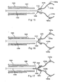
- FIGS. 13A-13B are, respectively, a side view and a top view of an alternative clip of the present invention.
- FIG. 14 is a side-sectional view illustrating a method of deploying the clip of FIGS. 13A-13B .
- FIG. 15 is a side-sectional view illustrating an alternative method of deploying the clip of FIGS. 13A-13B .
- FIG. 16 is a side-sectional view illustrating an alternative method of deploying the clip of FIGS. 13A-13B .
- FIG. 17 is a side-sectional view illustrating an alternative method of deploying the clip of FIGS. 13A-13B .
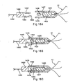
- FIGS. 18A-18C are side-sectional views illustrating an alternative retainer system.
- FIG. 19 is a side-sectional view illustrating a clip retaining apparatus.
- proximal refers to a direction that is generally towards a physician during a medical procedure
- distal refers to a direction that is generally towards a target site within a patent's anatomy during a medical procedure.
- the present invention provides a clip device for tissue or the like.
- Clip device 10 includes clip 12 with proximal end 14 having three arms 16 extending from the proximal end. Each arm is preferably inwardly bent at its end 18 to better grasp the tissue. While three arms are preferred, it is contemplated that fewer than or more than three arms may be used. For example, clip 12 may have two or four arms.
- the clip may be made from any suitable resilient material such as stainless steel, nitinol, plastic, and the like.
- the arms may have a cross-sectional shape that is round, square, triangular, pie-shaped, truncated cone, and the like.
- the proximal end 14 of the clip comprises first retainer 20 attached to the arms.
- the first retainer is permanently attached to the arms.
- the retainer preferably is provided with a shape that will complement a shape provided on a second retainer so that the first and second retainers will matingly join with each other.
- first retainer 20 has proximal end 22 and distal end 24, with notch 26 being disposed therebetween.
- proximal end 22 approximates the shape of a half-cylinder having a flat top surface 25, as depicted in FIG. 3 .
- this shape advantageously provides secure mating with complementary second retainer 60 without increasing the diameter beyond that of the first end of the retainer.
- Clip device 10 also comprises outer sheath 30 (or an introducing tube) having an inner diameter that receives inner sheath 40.
- the inner sheath can be advanced and retracted independently of the outer sheath.
- Inner sheath 40 has an inner diameter that receives operating wire 50.
- Outer sheath 30 is attached at its proximal end to forward handle portion 80.
- Inner sheath 40 extends through forward handle portion 80 and is attached at its proximal end to middle handle portion 82, which is disposed proximally of the forward handle portion.
- Operating wire 50 extends through the forward and middle handle portions, and is attached at its proximal end to rearward handle portion 84, which telescopically extends over the proximal portion of the middle handle portion.
- longitudinal movement of the operating wire and the inner and outer sheaths with respect to each other is controlled by longitudinal manipulation of the forward, middle and rearward handles portions with respect to each other.
- Forward handle portion 80 preferably includes flushing port 86.
- the flushing port may comprise a standard male or female luer fitting, or any other valve mechanism that permits the injection of fluid therethrough.
- the flushing port is in fluid communication with an interior volume of forward handle portion 80, which in turn is in fluid communication with a cavity or gap 88 that is disposed between the inner and outer sheaths. Accordingly, any fluid injected through flushing port 86 will necessarily enter cavity 88 between the inner and outer sheaths, and will subsequently exit cavity 88 near distal end 90 of outer sheath 30 (see FIG. 2 ). In other words, the fluid injected through the flushing port will exit the clip device near the clip.
- the cavity can be disposed inside inner sheath 40, or either the inner or the outer sheath may comprise a lumen disposed therein through which fluid can be passed along the length thereof.
- the flushing port could be alternatively located on either of the middle or rearward handle portions, or on a portion of the outer sheath distally of any of the handle portions.
- second retainer 60 is attached to the distal end of operating wire 50.
- second retainer 60 is complementary to first retainer 20 so that the first and second retainers can be matingly joined.
- second retainer 60 has proximal end 64 and distal end 62, with notch 66 being disposed therebetween.
- distal end 62 approximates the shape of a half-cylinder having a flat surface 65, as depicted in FIG. 3A .
- first and second retainers are joined with each other by locating flat surface 25 of first retainer 20 within notch 66 of second retainer 60, and by locating flat surface 65 of second retainer 60 within notch 26 of first retainer 20.
- first and second retainers form a substantially continuous cylinder shape having substantially the same outer diameter from proximal end 64 of second retainer 60 to distal end 24 of first retainer 20, as shown in FIG. 3A .
- sliding ring 70 is provided and has a first inner diameter 76 slightly larger than an outer diameter of first retainer 20 and second retainer 60.
- first inner diameter 76 of sliding ring 70 is such that the sliding ring can slide over the retainers, yet hold and maintain them in a mating position.
- sliding ring 70 can slide toward the ends of arms 16 of clip 12, causing the arms to move to a closed position, as explained below.
- outer sheath 30 is retracted to expose inner sheath 40, operating wire 50, and second retainer 60.
- Clip 12 is provided and first retainer 20 is matingly joined with second retainer 60, as described with respect to FIG. 3A above.
- Sliding ring 70 is placed over first retainer 20 and second retainer 60 so that they are maintained in a joined position. Sliding ring 70, having the retainers secured therein, then is disposed distal to inner sheath 40 and within outer sheath 30.
- outer sheath 30 is pushed toward the distal end of inner sheath 40 and beyond the clip, causing the arms of the clip to close.
- outer sheath 30 is introduced into a body cavity via a working channel of an endoscope (not shown) that has been previously inserted into the body cavity. While the body cavity is observed via the endoscope, the distal end portion of outer sheath 30 is guided to a part to be treated.
- a fluid such as saline is injected through flushing port 86 on forward handle portion 80.
- the fluid enters the cavity or gap between inner sheath 40 and outer sheath 30, and exits the distal end of the outer sheath.
- the fluid floods the area so as to flush any blood or bodily fluids away from the part to be treated.
- the injection of fluid is continued and/or repeated as necessary during the following steps so as to keep the area free of blood and other bodily fluids.
- a vacuum force may be applied to flushing port 86 so as to create suction within the cavity or gap between the inner and outer sheaths. This suction can be used to remove blood or other bodily fluids from the area surrounding the part to be treated.
- outer sheath 30 is retracted proximally to expose clip 12, which causes arms 16 to extend in a radially outward direction, as generally depicted.
- Inner sheath 40 is then advanced towards clip 12, causing sliding ring 70 to slide toward arms 16 of clip 12 and causing the arms to close, thereby grasping the tissue and facilitating tissue closure.
- Inner sheath 40 is then retracted and when the distal end of the inner sheath passes the first and second retainers, they detach and release from each other. Clip 12 is left inside the body cavity, holding the tissue. After disengaging the retainers, the clip operating device is removed from the channel of the endoscope.
- the distal opening 77 of sliding ring 70 has a second inner diameter smaller than a first diameter on first retainer 20.
- the sliding ring is not removable from the clip.
- the sliding ring can be located adjacent the proximal end of the clip so that the arms are in an open position. The sliding ring can then be moved to a position toward the ends of the arms to close them.
- the three arms 16a-16c of clip 12 comprise kinks 92a, 92b and 92c, respectively, which may be formed by bending or warping portions of the arms as depicted.
- the distal opening 77 of sliding ring 70 has a second inner diameter configured to frictionally engage kinks 92a-92c of the three arms 16a-16c. In use, sliding ring 70 slides toward the ends of arms 16a-16c of clip 12, causing the arms to move to a closed position, as explained above.
- kinks 92a-92c preferably become wedged within distal opening 77 and limit further distal movement of sliding ring 70.
- kinks 92a-92c serve as distal stop elements to ensure that the sliding ring cannot pass distally over the clip.
- the three arms 16a-16c of clip 12 comprise increased diameter portions 94a, 94b and 94c, respectively.
- Increased diameter portions 94a-94c may have diameters slightly greater than remaining portions of arms 16a-16c.
- the distal opening 77 of sliding ring 70 has a second inner diameter configured to frictionally engage increased diameter portions 94a-94c of the three arms 16a-16c. In use, sliding ring 70 slides toward the ends of arms 16a-16c of clip 12, causing the arms to move to a closed position, as explained above.
- the increased diameter portions 94a-94c preferably become wedged within distal opening 77 and limit further distal movement of sliding ring 70 to ensure that the sliding ring cannot pass distally over the clip.
- FIGS. 4-12 various alternative release mechanisms for deploying a clip device are described.
- the release mechanisms described in FIGS. 4-12 may be used in conjunction with apparatus described in FIGS. 1-3 .
- outer sheath 30, inner sheath 40, operating wire 50, sliding ring 70, forward handle portion 80, middle handle portion 82, rearward handle portion 84 and flushing port 86 may be used in the embodiments of FIGS. 4-12 .
- clip 12 may be provided in accordance with the embodiments described above, e.g., comprising three arms 16 and preferably having an inward bend 18 at its distal end to facilitate hemostasis.
- Alternative clip device 110 comprises first retainer 120 and second retainer 160.
- First retainer 120 is operably attached to arms 16 of clip 12.
- Proximal end 162 of second retainer 160 is attached to operating wire 50, as shown in FIG. 4 .
- First retainer 120 and second retainer 160 preferably are cylindrical in cross-sectional shape and have substantially identical outer diameters when mating, as described below.
- First retainer 120 comprises partially rounded notch 124 formed therein, and has rounded knob 125 formed proximal to notch 124.
- second retainer 160 comprises partially rounded notch 164 formed therein, and has rounded knob 165 disposed distal to notch 164.
- rounded knob 165 is aligned with notch 124
- rounded knob 125 is aligned with notch 164, as shown in FIG. 4 , thereby securing first retainer 120 to second retainer 160.
- the first and second retainers are matingly held together because inner sheath 40 and/or sliding ring 70 at least partially overlaps with both retainers, thereby inhibiting movement of the retainers with respect to each other.
- clip device 110 is advanced to a target site through a working channel of an endoscope (not shown).
- the clip device is advanced in the state depicted in FIG. 4 , with the exception that outer sheath 30 is distally advanced to cover arms 16 of clip 12 to constrain the clip within the delivery device.
- outer sheath 30 is retracted proximally to expose clip 12 and permit radial expansion of arms 16, as depicted in FIG. 4 .
- inner sheath 40 is advanced distally to abut sliding ring 70, causing the sliding ring to be advanced distally towards clip 12 and causing the arms of clip 12 to close radially inward to grasp tissue and promote hemostasis.
- inner sheath 40 is retracted proximally past first retainer 120 and second retainer 160, thereby exposing the coupling region between the retainers.
- retainers since the retainers are no longer radially constrained, they will releasably detach from one another. It is important to note that since the engaging portions of the retainers are rounded knobs, it may be less likely that the retainers will get caught on one another after deployment.
- First retainer 120 which is attached to clip 12, remains inside the body.
- Second retainer 160 which is attached to operating wire 50, is retracted via the operating wire.
- Clip device 210 comprises first retainer 220 and second retainer 260.
- First retainer 220 is operably attached to arms 16 of clip 12, while second retainer 260 is attached to the distal end of operating wire 50, as generally described above.
- first retainer 220 has socket 222 formed therein, which preferably comprises a hole formed laterally therethrough.
- Channel 224 is disposed between socket 222 and the proximal end of first retainer 220, as shown in FIG. 5A .
- First retainer 220 further comprises proximal arms 228 and 229, through which channel 224 extends.
- proximal arms 228 and 229 have a relaxed or biased state in which they are bowed radially outward, as shown in FIG. 5B . In this state, channel 224 is significantly opened.
- Second retainer 260 has wire 265 coupled to its distal end, and further comprises ball 267 attached to wire 265, as shown in FIG. 5A .
- wire 265 fits within channel 224, while ball 267 fits within socket 222, as depicted in FIG. 5A . Therefore, first retainer 220 is coupled to second retainer 260.
- the first and second retainers are securely held together because inner sheath 40 and/or sliding ring 70 at least partially overlaps with both retainers, thereby inhibiting outward movement of the retainers, and in particular, proximal arms 228 and 229 of first retainer 220.
- Clip device 210 is advanced to a target site through a working channel of an endoscope, as generally described above.
- outer sheath 30 is retracted proximally to expose clip 12 and permit radial expansion of arms 16, as shown in FIG. 5A .
- Inner sheath 40 then is advanced distally to abut sliding ring 70, causing the sliding ring to be advanced distally towards clip 12 arid causing the arms of clip 12 to close inward to grasp tissue and promote hemostasis, as described above.
- inner sheath 40 is retracted proximally past first retainer 220 and second retainer 260, thereby exposing the coupling region between the retainers.
- proximal arms 228 and 229 are no longer radially constrained, they assume the configuration shown in FIG. 5B and permit ball 267 to detach from socket 222.
- First retainer 220 which is attached to clip 12, remains inside the body, while second retainer 260 is retracted via operating wire 50.
- second retainer 260 is eliminated and ball 267 is connected directly to operating wire 50.
- first retainer 220' comprises angled channel 222' formed therein.
- Angled channel 222' may be formed partially through first retainer 220', or bored all the way through.
- angled channel 222' is formed partially through the proximal end of first retainer 222', thereby forming a space through which operating wire 50 may extend.
- the distal end of operating wire 50 is coupled to ball 267', which is captured within channel 222' when covered by inner sheath 40 or sliding ring 70, as depicted in FIG. 5C .
- operating wire 50 may be retracted proximally and ball 267' will exit the proximal end of angled channel 222' to disengage the clip from the delivery apparatus.
- Clip device 310 comprises first retainer 320 and second retainer 360, which are releasably secured together by loop member 363.
- first retainer 320 preferably comprises notch 325 formed therein and has hook member 326 disposed proximal to the notch, as shown in FIG. 6 .
- Second retainer 360 has a proximal end attached to operating wire 50, and has a distal end having loop member 363 extending therefrom.
- loop member 363 is placed over hook member 326, as shown in FIG. 6 , thereby securely coupling first retainer 320 to second retainer 360.
- Sliding ring 70 is advanced over at least notch 325 to ensure that loop member 363 cannot be inadvertently detached.
- Clip device 310 then is advanced to a target site through a working channel of an endoscope, as generally described above.
- outer sheath 30 is retracted proximally to expose clip 12 and permit radial expansion of arms 16.
- Inner sheath 40 is advanced distally to abut sliding ring 70, causing the sliding ring to be advanced distally towards clip 12 and causing the arms of clip 12 to close inward, as described above.
- Inner sheath 40 then is retracted proximally to uncover first retainer 320 and second retainer 360.
- loop member 363 is no longer radially constrained about hook member 326, which permits first retainer 320 to disengage from second retainer 360.
- the proximal face of hook member 326 can be angled to facilitate movement of loop member 363 out of notch 325.
- second retainer 360 may be eliminated and operating wire 50 may comprise a loop member, i.e., similar to loop member 363, at its distal end.
- the loop member of operating wire 50 is directly coupled to hook member 326 of first retainer 320.
- clip device 410 comprises first retainer 420 and second retainer 460, which are releasably secured together by frangible element 418.
- the frangible element is designed to break apart in a controlled manner when a sufficient tensile force is imposed upon it, as explained in more detail below.
- second retainer 460 is shown in the form of a cable that extends proximally within inner sheath 40.
- operating wire 50 may be coupled to a proximal region of second retainer 460 in a fashion similar to the other embodiments described above.
- second retainer 460 may be omitted and operating wire 50 may be coupled directly to first retainer 420, wherein operating wire 50 may comprise an integrally formed, frangible distal region.
- clip 12' comprises three arms 16a, 16b and 16c having stop elements 97a. 97b and 97c, respectively.
- the stop elements preferably comprise a bead-shaped, oval-shaped, or circular-shaped metal material, or any other suitable shape.
- the stop elements may be disposed on an outer surface of one or more of arms 16a, 16b and 16c and soldered or otherwise attached proximal to ends 18 of the arms. Alternatively, the stop elements may be formed integrally with their respective arms during manufacture. Stop elements 97a, 97b and 97c serve multiple purposes. One purpose is to ensure that sliding ring 70' cannot be advanced over the distal end of clip 12'. Another purpose is to limit the amount of closing force that can be applied to arms 18 of clip 12'.
- stop elements engage distal end 475 of sliding ring 70' to facilitate disengagement of the first retainer from the second retainer, e.g., when retracting the second retainer with respect to the first retainer, or rotating the retainers with respect to each other, as explained more fully below.
- distal end 475 of sliding ring 70' preferably comprises three channels 497a, 497b and 497c (see FIG. 7B ) which are configured to permit movement of arms 16a, 16b and 16c therethrough, respectively.
- stop elements 97a, 97b and 97c are sized so that they cannot pass completely through the channels. Therefore, when sliding ring 70' is advanced distally over clip 12', arms 16a, 16b and 16c pass through channels 497a, 497b and 497c, respectively, but the stop elements serve as distal stop elements to ensure that the sliding ring cannot pass distally over the clip.
- Sliding ring 70' comprises depressions 498a, 498b and 498c, which extend from the distal tip of sliding ring 70' into channels 497a, 497b and 497c, respectively (see FIG. 7B ).
- Stop elements 97a, 97b and 97c preferably are sized to be at least partially seated within depressions 498a, 498b and 498c, respectively.
- the stop elements may lockingly engage their respective depressions, e.g., using a snap-fit, thereby ensuring that sliding ring 70' cannot disengage from clip 12'.
- clip device 410 is advanced to a target site through a working channel of an endoscope, as generally described above.
- the proximal end of first retainer 420 is coupled to the distal end of second retainer 460 using frangible element 418.
- outer sheath 30 is retracted proximally to expose clip 12 and permit radial expansion of arms 16.
- Inner sheath 40 is advanced distally to abut sliding ring 70', causing the sliding ring to be advanced distally towards clip 12' and causing the arms of clip 12' to close inward, as described above.
- Stop elements 97a, 97b and 97c engage depressions 498a, 498b and 498c, respectively, to ensure that the sliding ring is not advanced distally past the end of the clip.
- inner sheath 40 is held steady while second retainer 460 (or operating wire 50 coupled to second retainer 460) is retracted proximally.
- the retraction of second retainer 460 with respect to first retainer 420 imposes a tensile force upon frangible element 418, thereby breaking the frangible element and detaching the retainers.
- a physician will be able to sense when the frangible element has been broken and the retainers have detached.
- clip 12' will be held steady and not displaced from engagement with the tissue. Specifically, after sliding ring 70' has been advanced distally and has engaged stop elements 97a, 97b and 97c, the stop elements prohibit proximal retraction of clip 12' with respect to sliding ring 70'. Since inner sheath 40 is held steady and prevents proximal retraction of sliding ring 70', clip 12' cannot be retracted proximally, either. This helps prevent excessive forces from being applied to the tissue.
- clip 12' and sliding ring 70' preferably are provided as described in FIGS. 7A-7B above. Therefore, clip 12' comprises stop elements 97a, 97b and 97c, which are sized to be at least partially be seated within depressions 498a, 498b and 498c, respectively, at the distal end of sliding ring 70' (see FIG. 7B ).
- Clip device 510 comprises first retainer 520 and second retainer 560, which are releasably secured together by magnetic forces, i.e., first retainer 520 has a first magnetic force and second retainer 560 has an opposing magnetic force.
- inner sheath 40 is advanced distally to cause sliding ring 70' to close arms 16a, 16b and 16c.
- stop elements 97a, 97b and 97c of clip 12' engage the depressions in sliding ring 70'.
- Inner sheath 40 then is held steady while operating wire 50 is retracted proximally, thereby overcoming the magnetic force and causing second retainer 560 to detach from first retainer 520.
- distal end 564 of second retainer 560 separates from proximal end 522 of first retainer 520, and second retainer 560 becomes retracted further proximally within inner sheath 40.
- inner sheath 40 is retracted proximally, and all of the components (except clip 12' attached to First retainer 520) are removed through the working channel of the endoscope.
- clip 12' and sliding ring 70' preferably are provided as described in FIGS. 7A-7B above. Therefore, clip 12' comprises stop elements 97a, 97b and 97c, which are sized to be at least partially be seated within depressions 498a, 498b and 498c, respectively, at the distal end of sliding ring 70' (see FIG. 7B ).
- Clip device 610 comprises first retainer 620 and second retainer 660, which are releasably secured together by a ball bearing and detent arrangement.
- first retainer 620 has inner bore 627 formed in its proximal end.
- Ball elements 642 and 643 are coupled to opposing exterior regions of first retainer 620 and partially extend into bore 627, as shown in FIG. 9A .
- the ball elements also extend radially outward towards sliding ring 70', and preferably contact the sliding ring, as depicted in FIG. 9A .
- Ball elements 642 and 643 are movable, but not removable, relative to first retainer 620.
- Second retainer 660 has an outer diameter that is less than the diameter of bore 627 of first retainer 620, thereby allowing second retainer 660 to be disposed within the bore. Second retainer 660 also has opposing notches 662 and 663 formed therein, which are sized to receive an outer portion of ball elements 642 and 643, respectively, as described below.
- clip device 610 is advanced to a target site through a working channel of an endoscope, as generally described above.
- sliding ring 70' and/or inner sheath 40 are disposed over ball elements 642 and 643, thereby urging the ball elements in an inward direction into a portion of notches 662 and 663, respectively.
- ball elements 642 and 643 substantially prohibit longitudinal movement of first retainer 620 with respect to second retainer 660, as shown in FIG. 9A .
- outer sheath 30 is retracted proximally to expose clip 12' and permit radial expansion of arms 16.
- Inner sheath 40 is advanced distally to abut sliding ring 70', causing the sliding ring to be advanced distally towards clip 12' and causing the arms of clip 12' to close inward, as described above.
- Inner sheath 40 then is retracted proximally past second retainer 660.
- sliding ring 70' and/or inner sheath 40 no longer constrain ball elements 642 and 643, the ball elements are permitted to move radially outward, i.e., out of notches 662 and 663.
- second retainer 660 may be retracted proximally via operating wire 50, and ball elements 642 and 643 will not catch on their respective detents.
- ball elements 642 and 643 may be deformable when subjected to a sufficient tensile release force.
- FIG. 9B The embodiment of FIG. 9B is similar to that described in FIG. 9A , with a main exception that one or more rivet elements 642' and 643' are employed in lieu of ball elements 642 and 643.
- Rivet element 642' preferably comprises a first end having flat surface 652 and a second end having enlarged rounded region 653. A smaller diameter portion extends between flat surface 652 and rounded region 653. The smaller diameter portion is disposed through a hole in first retainer 620', as shown in FIG. 9B , to contain rivet element 642'.
- clip device 710 preferably comprises two opposing ball elements 742 and 743 that selectively permit coupling of first retainer 720 and second retainer 760.
- First retainer 720 has inner bore 727 formed in its proximal end, which is adapted to receive a reduced diameter distal region of second retainer 760, as shown in FIG. 10A .
- First retainer 720 further comprises first and second notches 722 and 723 formed in bore 727, while the distal region of second retainer 760 has recesses 762 and 763 formed therein.
- Recesses 762 and 763 are configured to contain a substantial portion of ball elements 742 and 743, respectively, while a portion of the ball elements may extend outside of the confines of the recesses, as depicted in FIG. 10A .
- the recesses are configured, however, to never permit the ball elements to escape therefrom.
- biasing means 775 e.g., a compression spring, is disposed within recess 762.
- the biasing means is disposed beneath ball element 742 to bias the ball element radially outward, i.e., towards notch 722.
- a second biasing means (not shown) preferably is used to bias ball element 743 radially outward in the same manner.
- clip device 710 is advanced to a target site through a working channel of an endoscope, as generally described above.
- ball elements 742 and 743 are aligned with notches 722 and 723, respectively.
- the biasing means bias their respective ball elements radially outward into their respective notches to securely couple first retainer 720 to second retainer 760.
- second retainer 760 may be retracted proximally via operating wire 50. Stop elements 97a, 97b and 97c may engage depressions 498a, 498b and 498c, respectively, in sliding ring 70' (see FIG. 7B ).
- the intentional retraction of second retainer 760 by a physician will overcome the force provided by biasing means 775, thereby causing ball elements 742 and 743 to be forced radially inward and permitting disengagement of the two retainers.
- ball elements 742 and 743 may be deformable when subjected to a sufficient tensile release force.
- FIG. 10B The embodiment of FIG. 10B is similar to that described in FIG. 10A , with a main exception that one or more biased elements 742' and 743' are employed in lieu of ball elements 742 and 743.
- Biased elements 742' and 743' preferably are integrally formed with reduced diameter distal region 765 of second retainer 760', as shown in FIG. 10B .
- Biased elements 742' and 743' have a predetermined configuration in which they are biased radially outward into notches 722' and 723', respectively, to secure second retainer 760' to first retainer 720'.
- second retainer 760' When it is desired to disengage the retainers, second retainer 760' is retracted proximally with respect to first retainer 720' to urge biased elements 742' and 743' radially inward, i.e., out of notches 722' and 723'. Therefore, second retainer 760' may disengage from first retainer 720'.
- FIGS. 9-10 it will be apparent that although two opposing ball elements are shown, only one ball element may be employed, or alternatively, three or more may be used. Additionally, while ball-shaped elements are depicted, it will be apparent that these elements may comprise other shapes, such as oval-shaped elements, cone-shaped elements, and so forth.
- clip 12' comprises stop elements 97a, 97b and 97c, which are sized to be at least partially be seated within depressions 498a, 498b and 498c, respectively, at distal end 475 of sliding ring 70' (see FIG. 7B ).
- Clip device 810 comprises first retainer 820 and second retainer 860.
- First retainer 820 has bore 825 formed in its proximal end.
- Bore 825 has internal threading 827, which is configured to releasably mate with external threading 862, which is disposed on a distal region of second retainer 860.
- Torque cable 815 is coupled to a proximal region of second retainer 860 and preferably spans the entire length of the delivery system.
- inner sheath 40' and sliding ring 70" are similar to the embodiments described above. However, the distal end of inner sheath 40' is configured to mate with the proximal end of sliding ring 70" to inhibit rotational movement therebetween, for purposes explained below. In one embodiment, the distal end of inner sheath 40' comprises at least one notch 442 that is configured to mate with at least one corresponding knob 443 extending from the proximal end of sliding ring 70", as shown in FIG. 11B .
- clip device 810 is advanced to a target site through a working channel of an endoscope, as generally described above.
- first retainer 820 is secured to second retainer 860 by engaging their respective internal and external threaded regions.
- torque cable 815 is rotated in a direction that causes the threaded regions to disengage.
- torque cable 815 and second retainer 860 may be retracted proximally via inner sheath 40', while first retainer 820 attached to clip 12' is left inside the patient.
- stop elements 97a, 97b and 97c engage the depressions in sliding ring 70".
- the stop elements may lock into engagement with the depressions in sliding ring 70", e.g., using a snap-fit.
- notches 442 of inner sheath 40' mate with corresponding knobs 443 of sliding ring 70" (see FIG. 11B ) to prevent rotational movement of the inner sheath with respect to the sliding ring. Therefore, by holding inner sheath 40' steady while rotating torque cable 815 relative thereto, second retainer 860 is rotated with respect to first retainer 820, thereby causing the retainers to disengage.
- clip device 910 comprises first retainer 920 and second retainer 960.
- First retainer 920 has bore 925 formed in its proximal end, and further comprises first and second inwardly-directed knobs 927 and 928 projecting into bore 925, as shown in FIG. 12 .
- Second retainer 960 has proximal and distal ends, and further has an outer diameter that is slightly smaller than an inner diameter of bore 925.
- Axial channels 967 and 968 are formed in the distal end of second retainer 960, preferably 180 degrees apart, and extend longitudinally from the distal end towards the proximal end, as shown in FIG. 12 .
- axial channel 967 transitions into circumferential channel 977, which preferably extends about 90 degrees around the outer circumference of second retainer 960.
- axial channel 968 transitions into circumferential channel 978, which extends about 90 degrees around the outer circumference of second retainer 960, as shown in FIG. 12 .
- Channels 967, 968, 977 and 978 preferably are etched into an exterior surface of second retainer 960, which may be formed of stainless steel or the like.
- Knob 927 of first retainer 920 is sized for movement within channels 967 and 977, while knob 928 is sized for movement within channels 968 and 978, as described below.
- clip device 910 is advanced to a target site through a working channel of an endoscope, as generally described above.
- first retainer 920 is secured to second retainer 960 by aligning knobs 927 and 928 with axial channels 967 and 968, respectively.
- Second retainer 960 is moved towards first retainer 920 to cause the knobs to slide within their respective axial channels.
- knobs 927 and 928 reach the proximal portion of their respective axial channels
- second retainer 960 is rotated about 90 degrees with respect to first retainer 920, thereby causing knobs 927 and 928 to be advanced within their respective circumferential channels 977 and 978.
- first and second retainers 920 and 960 are coupled together, and longitudinal movement of the retainers with respect to each other is substantially prohibited.
- Clip 12' may then be deployed and secured to tissue by advancing sliding ring 70" of FIG. 11B .
- torque cable 915 which is operably coupled to the proximal end of second retainer 960, is rotated about 90 degree in a direction opposite the direction used to lock the retainers together. This rotation causes knobs 927 and 928 to be aligned with axial channels 967 and 968, respectively.
- second retainer 960 may be retracted proximally to cause knobs 927 and 928 to slide within axial channels 967 and 968, respectively, thereby unlocking the retainers.
- torque cable 915 and second retainer 960 may be retracted proximally through inner sheath 40, while first retainer 920 attached to clip 12 is left inside the patient. It will be apparent that although two opposing knobs are shown in FIG. 12 , only one knob/channel arrangement may be employed, or alternatively, three or more may be used.
- clip device 910 preferably employs clip 12', inner sheath 40' and sliding ring 70", as described in FIGS. 11A-11B above. As noted above, the use of such interlocking components will hold clip 12' rotationally stationary while second retainer 960 is rotated with respect to first retainer 920.
- Alternative clip 1012 comprises at least two arms, and in the embodiment of FIGS. 13A-13B , comprises three arms 1016a, 1016b and 1016c, each having proximal and distal ends.
- the distal ends of arms 1016a, 1016b and 1016c comprise bends 1018a, 1018b and 1018c, respectively, which are configured to engage tissue.
- clip 1012 is similar to clip 12, described above, with the main exception that arms 1016a, 1016b and 1016c comprise substantially flat regions along part or all of their length, as shown in FIGS. 13-13B . Moreover, the proximal ends of arms 1016a, 1016b and 1016c unite to form proximal end 1020 of clip 1012.
- Clip 1012 may be formed by cutting a flat clip having the desired number of arms (e.g., three) from a planar sheet of material, then bending the arms into the desired final shape.
- Proximal end 1020 has hole 1028 disposed therein, as shown in FIG. 13B .
- at least one slit 1029 may be formed around the circumference of hole 1028, for purposes described below.
- the apparatus comprises outer sheath 1030 and inner sheath 1040, which are similar to outer sheath 30 and inner sheath 40, as described above.
- the distal end of inner sheath 1040 is configured to engage collet 1070, which is disposed about the proximal end of clip 1012 and designed to close the clip, as explained below.
- arms 1016a, 1016b and 1016c comprise distal stop members 1025a, 1025b and 1025c, as shown in FIG. 13A and FIG. 14 .
- the distal stop members ensure that collet 1070 cannot be advanced distally over the clip.
- Collet 1070 is similar in design and function to sliding ring 70, 70' of the above-described embodiments.
- clip 1012 is coupled to operating wire 1050 prior to deployment.
- the distal end of operating wire 1050 is coupled to frangible member 1052, which in turn is coupled to knob 1054, as shown in FIG. 14 .
- frangible member 1052 may be integrally formed at the distal end of operating wire 1050.
- Frangible member 1052 extends through hole 1028 in proximal end 1020 of clip 1012, such that knob 1054 is confined distal to hole 1028, as shown in FIG. 14 .
- Clip 1012 is advanced to a target site with arms 1016a, 1016b and 1016c radially restrained by outer sheath 1030. Outer sheath 1030 is retracted to cause arms 1016a, 1016b and 1016c to deploy radially outward, as shown in FIG. 14 and generally described above.
- inner sheath 1040 is advanced distally to abut collet 1070 and distally advance collet 1070 over arms 1016a, 1016b and 1016c. The arms are urged radially inward to engage tissue and promote hemostasis.
- wire 1150 is advanced distally through hole 1028 of clip 1012, then loop 1152 is formed, and wire 1150 is pulled back through hole 1028.
- loop 1152 is secured distal to hole 1028, i.e., the loop will not pull through the hole in the absence of a significant force.
- collet 1070 is advanced via inner sheath 1040 and abuts distal stop members 1025a, 1025b and 1025c. Inner sheath 1040 then is held steady while wire 1150 is retracted proximally. At this time, an inwardly directed force causes loop 1152 to compress and pull through hole 1028, thereby separating clip 1012 from wire 1150.
- the distal end of operating wire 1250 extends through hole 1028 and is coupled to knob 1252, which is disposed distal to hole 1028.
- collet 1070 is advanced via inner sheath 1040 and abuts distal stop members 1025a, 1025b and 1025c. Inner sheath 1040 then is held steady while wire 1250 is retracted proximally. At this time, knob 1252 pulls through hole 1028, thereby separating clip 1012 from operating wire 1050.
- at least one slit 1029 is employed to facilitate retraction of knob 1252 through hole 1028.
- deformable member 1354 comprises at least two arms that extend radially outward in a relaxed state.
- the arms of deformable member 1354 may be coupled to rigid proximal section 1352, which in turn is coupled to operating wire 1350, as shown in FIG. 17 .
- operating wire 1350 may be coupled directly to deformable member 1354.
- proximal section 1352 or operating wire 1350 or is disposed through hole 1028, while deformable member 1354 is disposed distal to hole 1028, as shown in FIG. 17 .
- Collet 1070 is advanced via inner sheath 1040 and abuts distal stop members 1025a, 1025b and 1025c, and inner sheath 1040 then is held steady while operating wire 1350 is retracted proximally.
- the arms of deformable member 1354 are urged radially inward to pull deformable member 1354 through hole 1028, thereby separating clip 1012 from operating wire 1350.
- at least one slit 1029 may be employed to facilitate retraction of deformable member 1354 through hole 1028.
- First retainer 1420 has proximal and distal regions 1428 and 1425.
- Distal region 1425 comprises a generally cylindrical shape and is attached to clip 12.
- Proximal region 1428 preferably has a smaller diameter than distal region 1425, and may comprise a rounded proximal edge, as depicted in FIG. 18A .
- At least one notch 1427 is disposed between the proximal and distal regions, as shown in FIG. 18A .
- Second retainer 1460 comprises a generally cylindrical body having proximal and distal regions.
- the proximal region is attached to operating wire 1450.
- the distal region comprises bore 1465 having at least one knob 1463 extending therein, as shown in FIG. 18A .
- an exterior surface of second retainer 1460 has at least one protruding member 1462 extending radially outward, as depicted in FIG. 18A .
- sliding ring 1470 is disposed over first retainer 1420, as shown in FIG. 18A .
- Sliding ring 1470 comprises a flexible proximal region, as will be explained in FIG. 18B .
- sliding ring 1470 may comprise a lateral slit (not shown) disposed on a proximal region to enhance its radial flexibility and accommodate second retainer 1460, as explained below.
- a physician may attach second retainer 1460 to first retainer 1420 by distally advancing second retainer 1460.
- protruding member 1462 causes radial expansion of a proximal region of sliding ring 1470.
- knob 1463 is passed over proximal region 1428 of first retainer 1420, preferably with little or no resistance.
- proximal region 1428 of first retainer 1420 is disposed within the confines of bore 1465.
- this placement allows sliding ring 1470 to exert a resilient inward force upon protruding member 1462, thereby urging knob 1463 into notch 1427, as shown in FIG. 18C .
- an inner and outer sheath may be disposed over the apparatus and inserted into the patient, as generally set forth above.
- second retainer 1460 may be retracted proximally via operating wire 1450 to allow knob 1463 to disengage from notch 1427, thereby separating the retainers.
- Clip holder 1502 comprises proximal region 1508 and enlarged diameter distal region 1504.
- a taper 1507 is provided between the proximal and distal regions.
- Multiple clips 1520a, 1520b and 1520c are adapted to be pre-loaded into proximal region 1508, as shown in FIG. 19 .
- the arms 1512 of clips 1520a-c may be nested within bores 1530 of adjacent clips, or disposed proximal to adjacent clips as shown.
- First retainers 1520a-c may comprise portions adapted to mate with complementary portions on second retainer 1560.
- ball element 1562 may be adapted to engage with notch elements 1532 of second retainers 1520a-c.
- a physician may simply insert second retainer 1560 into clip holder 1502, engage a clip, and proceed to deploy the clip within a patient according the steps generally set forth above.
Landscapes
- Health & Medical Sciences (AREA)
- Surgery (AREA)
- Life Sciences & Earth Sciences (AREA)
- Heart & Thoracic Surgery (AREA)
- Nuclear Medicine, Radiotherapy & Molecular Imaging (AREA)
- Vascular Medicine (AREA)
- Engineering & Computer Science (AREA)
- Biomedical Technology (AREA)
- Reproductive Health (AREA)
- Medical Informatics (AREA)
- Molecular Biology (AREA)
- Animal Behavior & Ethology (AREA)
- General Health & Medical Sciences (AREA)
- Public Health (AREA)
- Veterinary Medicine (AREA)
- Surgical Instruments (AREA)
Applications Claiming Priority (2)
| Application Number | Priority Date | Filing Date | Title |
|---|---|---|---|
| US80991206P | 2006-06-01 | 2006-06-01 | |
| PCT/US2007/012754 WO2007142977A2 (en) | 2006-06-01 | 2007-05-30 | Release mechanisms for a clip device |
Publications (2)
| Publication Number | Publication Date |
|---|---|
| EP2020925A2 EP2020925A2 (en) | 2009-02-11 |
| EP2020925B1 true EP2020925B1 (en) | 2013-07-10 |
Family
ID=38698680
Family Applications (1)
| Application Number | Title | Priority Date | Filing Date |
|---|---|---|---|
| EP07777322.4A Not-in-force EP2020925B1 (en) | 2006-06-01 | 2007-05-30 | Release mechanisms for a clip device |
Country Status (6)
| Country | Link |
|---|---|
| US (1) | US20070282355A1 (ja) |
| EP (1) | EP2020925B1 (ja) |
| JP (2) | JP5204100B2 (ja) |
| AU (1) | AU2007255016A1 (ja) |
| CA (1) | CA2654004C (ja) |
| WO (1) | WO2007142977A2 (ja) |
Cited By (1)
| Publication number | Priority date | Publication date | Assignee | Title |
|---|---|---|---|---|
| DE102014220505A1 (de) * | 2014-10-09 | 2016-04-14 | Endox Feinwerktechnik Gmbh | Medizinisches Instrument |
Families Citing this family (158)
| Publication number | Priority date | Publication date | Assignee | Title |
|---|---|---|---|---|
| ES2717309T3 (es) | 2004-10-08 | 2019-06-20 | Covidien Lp | Aplicador endoscópico de grapas quirúrgicas |
| US8409222B2 (en) | 2004-10-08 | 2013-04-02 | Covidien Lp | Endoscopic surgical clip applier |
| US7819886B2 (en) | 2004-10-08 | 2010-10-26 | Tyco Healthcare Group Lp | Endoscopic surgical clip applier |
| US9763668B2 (en) | 2004-10-08 | 2017-09-19 | Covidien Lp | Endoscopic surgical clip applier |
| EP2875786B1 (en) | 2004-10-08 | 2017-02-01 | Covidien LP | Apparatus for applying surgical clips |
| WO2008045940A2 (en) * | 2006-10-10 | 2008-04-17 | Adrian Edward Park | Adjustable line and net retractors |
| EP1913881B1 (en) | 2006-10-17 | 2014-06-11 | Covidien LP | Apparatus for applying surgical clips |
| US8382773B2 (en) | 2007-03-26 | 2013-02-26 | Covidien Lp | Endoscopic surgical clip applier |
| JP5329526B2 (ja) | 2007-04-11 | 2013-10-30 | コヴィディエン リミテッド パートナーシップ | 外科用クリップアプライヤ |
| US8133242B1 (en) | 2007-04-27 | 2012-03-13 | Q-Tech Medical Incorporated | Image-guided extraluminal occlusion |
| CA2706860C (en) * | 2007-11-26 | 2017-08-01 | Eastern Virginia Medical School | Magnaretractor system and method |
| AU2009260236B2 (en) * | 2008-06-19 | 2014-06-12 | Boston Scientific Scimed, Inc. | Hemostatic clipping devices and methods |
| AU2009282596A1 (en) | 2008-08-19 | 2010-02-25 | Wilson-Cook Medical Inc. | Apparatus for removing lymph nodes or anchoring into tissue during a translumenal procedure |
| US20110208212A1 (en) | 2010-02-19 | 2011-08-25 | Zergiebel Earl M | Surgical clip applier |
| US8056565B2 (en) | 2008-08-25 | 2011-11-15 | Tyco Healthcare Group Lp | Surgical clip applier and method of assembly |
| US8465502B2 (en) | 2008-08-25 | 2013-06-18 | Covidien Lp | Surgical clip applier and method of assembly |
| US8409223B2 (en) | 2008-08-29 | 2013-04-02 | Covidien Lp | Endoscopic surgical clip applier with clip retention |
| US9358015B2 (en) | 2008-08-29 | 2016-06-07 | Covidien Lp | Endoscopic surgical clip applier with wedge plate |
| US8267944B2 (en) | 2008-08-29 | 2012-09-18 | Tyco Healthcare Group Lp | Endoscopic surgical clip applier with lock out |
| US8585717B2 (en) | 2008-08-29 | 2013-11-19 | Covidien Lp | Single stroke endoscopic surgical clip applier |
| WO2010042844A2 (en) * | 2008-10-10 | 2010-04-15 | Surgiquest, Incorporated | Internal retraction systems and devices |
| US9211125B2 (en) * | 2008-10-23 | 2015-12-15 | Microline Surgical, Inc. | Flexible clip applier |
| EP2373224A1 (en) * | 2008-12-09 | 2011-10-12 | Wilson-Cook Medical Inc. | Apparatus and methods for controlled release of tacking devices |
| AU2009335901B2 (en) * | 2008-12-19 | 2013-09-19 | Cook Medical Technologies Llc | Clip devices and methods of delivery and deployment |
| US8142451B2 (en) | 2009-01-26 | 2012-03-27 | Microline Surgical, Inc. | Actuator and detachable connector of flexible clip applier |
| CL2009000279A1 (es) | 2009-02-06 | 2009-08-14 | Biotech Innovations Ltda | Sistema de guia y traccion remota para cirugia mini-invasiva, que comprende: al menos una endopinza quirurgica y desprendible con medios de enganches y una porcion de material ferro magnaetico, una guia de introduccion de forma cilindrica, un mecanismo de desprendimiento, y al menos un medio de traccion remota con iman. |
| US8454630B2 (en) * | 2009-04-29 | 2013-06-04 | Cook Medical Technologies Llc | Endoscopic clipping device |
| WO2010138579A1 (en) | 2009-05-28 | 2010-12-02 | Wilson-Cook Medical Inc. | Tacking device and methods of deployment |
| US8517073B2 (en) * | 2009-07-16 | 2013-08-27 | Covidien Lp | Apparatus and method for joining similar or dissimilar suture products |
| US8403837B2 (en) * | 2009-08-13 | 2013-03-26 | Covidien Lp | Deployable jaws retraction device |
| US8459524B2 (en) | 2009-08-14 | 2013-06-11 | Covidien Lp | Tissue fastening system for a medical device |
| EP2467069A1 (en) * | 2009-08-19 | 2012-06-27 | Boston Scientific Scimed, Inc. | Multifunctional core for two-piece hemostasis clip |
| US8734469B2 (en) | 2009-10-13 | 2014-05-27 | Covidien Lp | Suture clip applier |
| BR112012011450A2 (pt) | 2009-10-30 | 2017-09-19 | Cook Medical Technologies Llc | aparelho para manter uma força sobre um tecido usando um membro de loop |
| US9186136B2 (en) | 2009-12-09 | 2015-11-17 | Covidien Lp | Surgical clip applier |
| US8545486B2 (en) | 2009-12-15 | 2013-10-01 | Covidien Lp | Surgical clip applier |
| US9339270B2 (en) | 2010-10-11 | 2016-05-17 | Cook Medical Technologies Llc | Medical devices with detachable pivotable jaws |
| EP2515770B1 (en) | 2009-12-22 | 2018-10-31 | Cook Medical Technologies LLC | Medical devices with detachable pivotable jaws |
| US10010336B2 (en) | 2009-12-22 | 2018-07-03 | Cook Medical Technologies, Inc. | Medical devices with detachable pivotable jaws |
| US8403945B2 (en) | 2010-02-25 | 2013-03-26 | Covidien Lp | Articulating endoscopic surgical clip applier |
| US8211121B1 (en) | 2010-03-06 | 2012-07-03 | Q-Tech Medical Incorporated | Methods and apparatus for image-guided extraluminal occlusion using clamping jaws |
| US9044240B2 (en) * | 2010-03-10 | 2015-06-02 | Boston Scientific Scimed, Inc. | Hemostasis clip |
| US8968337B2 (en) | 2010-07-28 | 2015-03-03 | Covidien Lp | Articulating clip applier |
| US8403946B2 (en) | 2010-07-28 | 2013-03-26 | Covidien Lp | Articulating clip applier cartridge |
| EP2603150B1 (en) | 2010-08-10 | 2016-05-04 | Cook Medical Technologies LLC | Clip devices and methods of delivery and deployment |
| AU2011316687B2 (en) | 2010-10-11 | 2014-10-30 | Cook Medical Technologies Llc | Medical devices with detachable pivotable jaws |
| US9011464B2 (en) | 2010-11-02 | 2015-04-21 | Covidien Lp | Self-centering clip and jaw |
| US8764774B2 (en) | 2010-11-09 | 2014-07-01 | Cook Medical Technologies Llc | Clip system having tether segments for closure |
| US9186153B2 (en) | 2011-01-31 | 2015-11-17 | Covidien Lp | Locking cam driver and jaw assembly for clip applier |
| US9775623B2 (en) | 2011-04-29 | 2017-10-03 | Covidien Lp | Surgical clip applier including clip relief feature |
| US20130131697A1 (en) | 2011-11-21 | 2013-05-23 | Covidien Lp | Surgical clip applier |
| US9364239B2 (en) | 2011-12-19 | 2016-06-14 | Covidien Lp | Jaw closure mechanism for a surgical clip applier |
| US9044258B2 (en) * | 2011-12-27 | 2015-06-02 | Specialty Surgical Instrumentation Inc. | Instrument with removable tip |
| US9364216B2 (en) | 2011-12-29 | 2016-06-14 | Covidien Lp | Surgical clip applier with integrated clip counter |
| US9107654B2 (en) | 2012-01-05 | 2015-08-18 | Cook Medical Technologies Llc | Attachment device for tissue approximation and retraction |
| US9408610B2 (en) | 2012-05-04 | 2016-08-09 | Covidien Lp | Surgical clip applier with dissector |
| US9532787B2 (en) | 2012-05-31 | 2017-01-03 | Covidien Lp | Endoscopic clip applier |
| US9113892B2 (en) | 2013-01-08 | 2015-08-25 | Covidien Lp | Surgical clip applier |
| US9968362B2 (en) | 2013-01-08 | 2018-05-15 | Covidien Lp | Surgical clip applier |
| US9750500B2 (en) | 2013-01-18 | 2017-09-05 | Covidien Lp | Surgical clip applier |
| US8764769B1 (en) | 2013-03-12 | 2014-07-01 | Levita Magnetics International Corp. | Grasper with magnetically-controlled positioning |
| US10010370B2 (en) | 2013-03-14 | 2018-07-03 | Levita Magnetics International Corp. | Magnetic control assemblies and systems therefor |
| EP3019093B1 (en) * | 2013-07-10 | 2018-08-29 | Boston Scientific Scimed, Inc. | Tissue grasping and wound closing clipping device |
| EP3035866B1 (en) * | 2013-08-21 | 2024-03-27 | Boston Scientific Scimed, Inc. | Devices for lumen occlusion |
| US9775624B2 (en) | 2013-08-27 | 2017-10-03 | Covidien Lp | Surgical clip applier |
| WO2015112645A1 (en) | 2014-01-21 | 2015-07-30 | Levita Magnetics International Corp. | Laparoscopic graspers and systems therefor |
| US9707005B2 (en) | 2014-02-14 | 2017-07-18 | Ethicon Llc | Lockout mechanisms for surgical devices |
| WO2015157116A1 (en) * | 2014-04-08 | 2015-10-15 | Boston Scientific Scimed, Inc. | Endoscopic closure device |
| US9801692B2 (en) * | 2014-08-07 | 2017-10-31 | Biomet Manufacturing, Llc | Instrument deployed tissue protector |
| US10702278B2 (en) | 2014-12-02 | 2020-07-07 | Covidien Lp | Laparoscopic surgical ligation clip applier |
| US9931124B2 (en) | 2015-01-07 | 2018-04-03 | Covidien Lp | Reposable clip applier |
| EP3244810B1 (en) | 2015-01-15 | 2020-03-18 | Covidien LP | Endoscopic reposable surgical clip applier |
| US10292712B2 (en) | 2015-01-28 | 2019-05-21 | Covidien Lp | Surgical clip applier with integrated cutter |
| US10159491B2 (en) | 2015-03-10 | 2018-12-25 | Covidien Lp | Endoscopic reposable surgical clip applier |
| EP3967244A1 (en) | 2015-04-13 | 2022-03-16 | Levita Magnetics International Corp. | Retractor devices |
| EP3282954B1 (en) | 2015-04-13 | 2021-07-28 | Levita Magnetics International Corp. | Grasper with magnetically-controlled positioning |
| JP6654396B2 (ja) * | 2015-10-07 | 2020-02-26 | オリンパス株式会社 | 接続構造体 |
| US10470775B2 (en) * | 2015-10-23 | 2019-11-12 | Hangzhou Ags Medtech Co., Ltd. | Ligation device |
| CN108348259B (zh) | 2015-11-03 | 2020-12-11 | 柯惠有限合伙公司 | 内窥镜手术夹具施加器 |
| US10390831B2 (en) | 2015-11-10 | 2019-08-27 | Covidien Lp | Endoscopic reposable surgical clip applier |
| CN108348255B (zh) | 2015-11-10 | 2020-11-27 | 柯惠有限合伙公司 | 可重复使用的内窥镜外科手术施夹器 |
| CA2999907A1 (en) | 2015-11-10 | 2017-05-18 | Covidien Lp | Endoscopic reposable surgical clip applier |
| JP6794369B2 (ja) * | 2015-11-30 | 2020-12-02 | 株式会社カネカ | 医療用クリップカートリッジ |
| EP3402417A4 (en) | 2016-01-11 | 2019-12-04 | Covidien LP | ENDOSCOPIC RESTABLE SURGICAL STAPLER APPLICATOR |
| CN108472027B (zh) | 2016-01-18 | 2020-12-29 | 柯惠有限合伙公司 | 内窥镜外科手术夹具施用器 |
| CA2958160A1 (en) | 2016-02-24 | 2017-08-24 | Covidien Lp | Endoscopic reposable surgical clip applier |
| US10973638B2 (en) * | 2016-07-07 | 2021-04-13 | Edwards Lifesciences Corporation | Device and method for treating vascular insufficiency |
| US10806464B2 (en) | 2016-08-11 | 2020-10-20 | Covidien Lp | Endoscopic surgical clip applier and clip applying systems |
| CN115005921A (zh) * | 2016-08-22 | 2022-09-06 | 波士顿科学有限公司 | 带套管接合的止血可再装载夹持装置 |
| US10531947B2 (en) | 2016-08-24 | 2020-01-14 | Terumo Cardiovascular Systems Corporation | Great vessel graft suturing aid |
| US11071553B2 (en) | 2016-08-25 | 2021-07-27 | Covidien Lp | Endoscopic surgical clip applier and clip applying systems |
| WO2018057461A1 (en) * | 2016-09-20 | 2018-03-29 | Boston Scientific Scimed, Inc. | Reloadable applicator for hemostatic clips |
| US10660651B2 (en) | 2016-10-31 | 2020-05-26 | Covidien Lp | Endoscopic reposable surgical clip applier |
| US10639044B2 (en) | 2016-10-31 | 2020-05-05 | Covidien Lp | Ligation clip module and clip applier |
| US10492795B2 (en) | 2016-11-01 | 2019-12-03 | Covidien Lp | Endoscopic surgical clip applier |
| US10426489B2 (en) | 2016-11-01 | 2019-10-01 | Covidien Lp | Endoscopic reposable surgical clip applier |
| US10610236B2 (en) | 2016-11-01 | 2020-04-07 | Covidien Lp | Endoscopic reposable surgical clip applier |
| US11045194B2 (en) * | 2016-12-06 | 2021-06-29 | Boston Scientific Scimed, Inc. | Compressive coupler for reloadable hemostasis clipping device |
| US10709455B2 (en) | 2017-02-02 | 2020-07-14 | Covidien Lp | Endoscopic surgical clip applier |
| AU2017397500A1 (en) | 2017-02-06 | 2019-07-11 | Covidien Lp | Surgical clip applier with user feedback feature |
| US10758244B2 (en) | 2017-02-06 | 2020-09-01 | Covidien Lp | Endoscopic surgical clip applier |
| US10660725B2 (en) | 2017-02-14 | 2020-05-26 | Covidien Lp | Endoscopic surgical clip applier including counter assembly |
| US10603038B2 (en) | 2017-02-22 | 2020-03-31 | Covidien Lp | Surgical clip applier including inserts for jaw assembly |
| US11583291B2 (en) | 2017-02-23 | 2023-02-21 | Covidien Lp | Endoscopic surgical clip applier |
| US10548602B2 (en) | 2017-02-23 | 2020-02-04 | Covidien Lp | Endoscopic surgical clip applier |
| US11020137B2 (en) | 2017-03-20 | 2021-06-01 | Levita Magnetics International Corp. | Directable traction systems and methods |
| EP3600077A4 (en) | 2017-03-21 | 2020-12-30 | Teleflex Medical Incorporated | STAPLE APPLICATOR WITH A STABILIZATION ELEMENT |
| EP3600082A4 (en) | 2017-03-21 | 2020-09-16 | Teleflex Medical Incorporated | SURGICAL STAPLE AND STAPLE APPLICATOR |
| CN110868944A (zh) | 2017-03-21 | 2020-03-06 | 泰利福医疗公司 | 用于施夹器的柔性稳定构件 |
| WO2018175605A1 (en) | 2017-03-21 | 2018-09-27 | Teleflex Medical Incorporated | Clip applier with replaceable tips |
| JP6873267B2 (ja) | 2017-03-21 | 2021-05-19 | テレフレックス メディカル インコーポレイテッド | 安定化部材を有するクリップアプライヤ |
| US10675043B2 (en) | 2017-05-04 | 2020-06-09 | Covidien Lp | Reposable multi-fire surgical clip applier |
| US10722235B2 (en) | 2017-05-11 | 2020-07-28 | Covidien Lp | Spring-release surgical clip |
| US10639032B2 (en) | 2017-06-30 | 2020-05-05 | Covidien Lp | Endoscopic surgical clip applier including counter assembly |
| US10660723B2 (en) | 2017-06-30 | 2020-05-26 | Covidien Lp | Endoscopic reposable surgical clip applier |
| US10675112B2 (en) | 2017-08-07 | 2020-06-09 | Covidien Lp | Endoscopic surgical clip applier including counter assembly |
| US10863992B2 (en) | 2017-08-08 | 2020-12-15 | Covidien Lp | Endoscopic surgical clip applier |
| US10932790B2 (en) | 2017-08-08 | 2021-03-02 | Covidien Lp | Geared actuation mechanism and surgical clip applier including the same |
| US10786262B2 (en) | 2017-08-09 | 2020-09-29 | Covidien Lp | Endoscopic reposable surgical clip applier |
| US10786263B2 (en) | 2017-08-15 | 2020-09-29 | Covidien Lp | Endoscopic reposable surgical clip applier |
| US10835341B2 (en) | 2017-09-12 | 2020-11-17 | Covidien Lp | Endoscopic surgical clip applier and handle assemblies for use therewith |
| US10758245B2 (en) | 2017-09-13 | 2020-09-01 | Covidien Lp | Clip counting mechanism for surgical clip applier |
| US10835260B2 (en) | 2017-09-13 | 2020-11-17 | Covidien Lp | Endoscopic surgical clip applier and handle assemblies for use therewith |
| US10653429B2 (en) | 2017-09-13 | 2020-05-19 | Covidien Lp | Endoscopic surgical clip applier |
| US11116513B2 (en) | 2017-11-03 | 2021-09-14 | Covidien Lp | Modular surgical clip cartridge |
| US10932791B2 (en) | 2017-11-03 | 2021-03-02 | Covidien Lp | Reposable multi-fire surgical clip applier |
| US10828036B2 (en) | 2017-11-03 | 2020-11-10 | Covidien Lp | Endoscopic surgical clip applier and handle assemblies for use therewith |
| US11376015B2 (en) | 2017-11-03 | 2022-07-05 | Covidien Lp | Endoscopic surgical clip applier and handle assemblies for use therewith |
| US10945734B2 (en) | 2017-11-03 | 2021-03-16 | Covidien Lp | Rotation knob assemblies and surgical instruments including the same |
| WO2019108387A1 (en) * | 2017-11-28 | 2019-06-06 | Boston Scientificscimed, Inc. | Self-aligning pullwire for reloadable hemostasis clipping device |
| US10722236B2 (en) | 2017-12-12 | 2020-07-28 | Covidien Lp | Endoscopic reposable surgical clip applier |
| US10743887B2 (en) | 2017-12-13 | 2020-08-18 | Covidien Lp | Reposable multi-fire surgical clip applier |
| US10959737B2 (en) | 2017-12-13 | 2021-03-30 | Covidien Lp | Reposable multi-fire surgical clip applier |
| US10849630B2 (en) | 2017-12-13 | 2020-12-01 | Covidien Lp | Reposable multi-fire surgical clip applier |
| US11051827B2 (en) | 2018-01-16 | 2021-07-06 | Covidien Lp | Endoscopic surgical instrument and handle assemblies for use therewith |
| CN109833191A (zh) * | 2018-02-10 | 2019-06-04 | 杨建明 | 直肠电子振动栓输送装置、直肠电子振动栓及其组合 |
| CN108210008A (zh) * | 2018-03-09 | 2018-06-29 | 江苏常美医疗器械有限公司 | 新型止血夹子装置 |
| US10993721B2 (en) | 2018-04-25 | 2021-05-04 | Covidien Lp | Surgical clip applier |
| US10786273B2 (en) | 2018-07-13 | 2020-09-29 | Covidien Lp | Rotation knob assemblies for handle assemblies |
| US11259887B2 (en) | 2018-08-10 | 2022-03-01 | Covidien Lp | Feedback mechanisms for handle assemblies |
| US11033256B2 (en) | 2018-08-13 | 2021-06-15 | Covidien Lp | Linkage assembly for reusable surgical handle assemblies |
| US11344316B2 (en) | 2018-08-13 | 2022-05-31 | Covidien Lp | Elongated assemblies for surgical clip appliers and surgical clip appliers incorporating the same |
| US11051828B2 (en) | 2018-08-13 | 2021-07-06 | Covidien Lp | Rotation knob assemblies and surgical instruments including same |
| US11246601B2 (en) | 2018-08-13 | 2022-02-15 | Covidien Lp | Elongated assemblies for surgical clip appliers and surgical clip appliers incorporating the same |
| US11278267B2 (en) | 2018-08-13 | 2022-03-22 | Covidien Lp | Latch assemblies and surgical instruments including the same |
| US11253267B2 (en) | 2018-08-13 | 2022-02-22 | Covidien Lp | Friction reduction mechanisms for handle assemblies |
| US11219463B2 (en) | 2018-08-13 | 2022-01-11 | Covidien Lp | Bilateral spring for surgical instruments and surgical instruments including the same |
| US11147566B2 (en) | 2018-10-01 | 2021-10-19 | Covidien Lp | Endoscopic surgical clip applier |
| WO2020136906A1 (ja) * | 2018-12-28 | 2020-07-02 | オリンパス株式会社 | 結紮装置および係合方法 |
| DE112019005835T5 (de) * | 2019-01-03 | 2021-10-14 | Olympus Corporation | Klammervorrichtung für große Defekte, Perforationen und Fisteln |
| US11524398B2 (en) | 2019-03-19 | 2022-12-13 | Covidien Lp | Gear drive mechanisms for surgical instruments |
| US11779340B2 (en) | 2020-01-02 | 2023-10-10 | Covidien Lp | Ligation clip loading device |
| US11723669B2 (en) | 2020-01-08 | 2023-08-15 | Covidien Lp | Clip applier with clip cartridge interface |
| CN215079215U (zh) * | 2020-11-05 | 2021-12-10 | 北京东林富士医疗器械有限责任公司 | 一种止血夹 |
| JP7389155B2 (ja) * | 2021-02-12 | 2023-11-29 | オリンパスメディカルシステムズ株式会社 | クリップ装置 |
| WO2022173024A1 (en) * | 2021-02-12 | 2022-08-18 | Olympus Medical Systems Corp. | Clip device and method of operating clip device |
| WO2023028250A1 (en) * | 2021-08-25 | 2023-03-02 | GastroLogic LLC | Endoscopic clip apparatus and methods |
| US20230270446A1 (en) | 2022-02-28 | 2023-08-31 | Olympus Medical Systems Corp. | Applicator, clip system, and related method of operation |
Family Cites Families (103)
| Publication number | Priority date | Publication date | Assignee | Title |
|---|---|---|---|---|
| US1510416A (en) * | 1922-04-15 | 1924-09-30 | Pietz Frederick | Forceps |
| US1578800A (en) * | 1926-01-19 | 1926-03-30 | Carl F Brandenberger | Grabbing tool |
| US2113246A (en) * | 1937-05-17 | 1938-04-05 | Wappler Frederick Charles | Endoscopic forceps |
| US2384697A (en) * | 1944-10-18 | 1945-09-11 | Riccardi Peter | Umbilical clip |
| US2968041A (en) * | 1958-09-25 | 1961-01-17 | John F Skold | Applicator for surgical clamps |
| US3166072A (en) * | 1962-10-22 | 1965-01-19 | Jr John T Sullivan | Barbed clips |
| US3378010A (en) * | 1965-07-28 | 1968-04-16 | Coldling | Surgical clip with means for releasing the clamping pressure |
| US3518993A (en) * | 1967-05-01 | 1970-07-07 | American Hospital Supply Corp | Surgical clip applicator |
| US3616497A (en) * | 1970-06-24 | 1971-11-02 | Vincent J Esposito Jr | Integral clamping instruments for medical and surgical applications |
| GB1426245A (en) * | 1973-03-09 | 1976-02-25 | Judge Int Ltd | Line gripping pegs |
| US3882854A (en) * | 1973-08-23 | 1975-05-13 | Research Corp | Surgical clip and applicator |
| JPS5320957Y2 (ja) * | 1973-11-14 | 1978-06-01 | ||
| JPS552966Y2 (ja) * | 1974-02-08 | 1980-01-24 | ||
| US4046149A (en) * | 1975-01-31 | 1977-09-06 | Olympus Optical Co., Ltd. | Instrument for removing a foreign substance from the body cavity of human being |
| US4169476A (en) * | 1977-08-12 | 1979-10-02 | Wolf Medical Instruments Corporation | Applicator for surgical clip |
| US4215871A (en) * | 1979-03-05 | 1980-08-05 | Vargus Ltd. | Hand held collet |
| AR218795A1 (es) * | 1979-12-11 | 1980-06-30 | Derechinsky V | Instrumento porta-clips para el "clipado" de vasos sanguineos |
| US4446865A (en) * | 1981-03-16 | 1984-05-08 | Ethicon, Inc. | Plastic ligating clips |
| US4394864A (en) * | 1981-04-15 | 1983-07-26 | Jeffrey Sandhaus | Apparatus and method for effecting occlusion of the vas deferens |
| US4394861A (en) * | 1981-05-11 | 1983-07-26 | Sciortino Lawrence A | Outside air breathing supply system |
| US4496090A (en) * | 1982-03-10 | 1985-01-29 | Crevier Paul H | Surgical stapler |
| US4458682A (en) * | 1982-08-02 | 1984-07-10 | Ethicon, Inc. | Non-metallic, bio-compatible hemostatic clips (ring lock clips) |
| US4512345A (en) * | 1982-09-30 | 1985-04-23 | United States Surgical Corporation | Surgical clip applying apparatus, and clips and clip train for use therein |
| US4492232A (en) * | 1982-09-30 | 1985-01-08 | United States Surgical Corporation | Surgical clip applying apparatus having fixed jaws |
| SE8303624A0 (sv) * | 1983-06-23 | 1984-12-24 | Packendorff Sven Elgert | Klädnypa |
| GB8422863D0 (en) * | 1984-09-11 | 1984-10-17 | Univ London | Sewing machine |
| US4821721A (en) * | 1985-01-14 | 1989-04-18 | Thomas J. Fogarty | Apparatus and method for applying hemostatic scalp clips |
| US4706668A (en) * | 1985-09-16 | 1987-11-17 | B & B Tools | Aneurysm clip pliers |
| DE3533423A1 (de) * | 1985-09-19 | 1987-03-26 | Wolf Gmbh Richard | Applikator-zangeneinsatz fuer chirurgische handhabe zur anwendung in der endoskopie |
| US4681107A (en) * | 1985-12-31 | 1987-07-21 | Kees Surgical Specialty Co. | Device for holding an aneurysm clip |
| US4796627A (en) * | 1986-08-26 | 1989-01-10 | Tucker Wilson H | Clip applicator and spreadable clips for use therein |
| US4735194C1 (en) * | 1987-01-13 | 2001-05-08 | Dept Of Veterans Affairs The U | Flexile endoscopic ligating instrument |
| US5100418A (en) * | 1987-05-14 | 1992-03-31 | Inbae Yoon | Suture tie device system and applicator therefor |
| US5478353A (en) * | 1987-05-14 | 1995-12-26 | Yoon; Inbae | Suture tie device system and method for suturing anatomical tissue proximate an opening |
| US5366459A (en) * | 1987-05-14 | 1994-11-22 | Inbae Yoon | Surgical clip and clip application procedures |
| US4945920A (en) * | 1988-03-28 | 1990-08-07 | Cordis Corporation | Torqueable and formable biopsy forceps |
| US4835824A (en) * | 1988-04-13 | 1989-06-06 | Durham Vaughn L | Medical clamp |
| US4971067A (en) * | 1988-05-05 | 1990-11-20 | Lee Bolduc | Biopsy instrument with a disposable cutting blade |
| US4880015A (en) * | 1988-06-03 | 1989-11-14 | Nierman David M | Biopsy forceps |
| US5486185A (en) * | 1989-01-30 | 1996-01-23 | Dexide, Inc. | Surgical apparatus |
| US4983176A (en) * | 1989-03-06 | 1991-01-08 | University Of New Mexico | Deformable plastic surgical clip |
| US5015249A (en) * | 1989-12-26 | 1991-05-14 | Nakao Naomi L | Endoscopic stapling device and method |
| US5049153A (en) * | 1989-12-26 | 1991-09-17 | Nakao Naomi L | Endoscopic stapling device and method |
| US5156609A (en) * | 1989-12-26 | 1992-10-20 | Nakao Naomi L | Endoscopic stapling device and method |
| US5222961A (en) * | 1989-12-26 | 1993-06-29 | Naomi Nakao | Endoscopic stapling device and related staple |
| US5062848A (en) * | 1990-03-07 | 1991-11-05 | Frazee John G | Hemostatic clip and applicator therefor |
| US5366458A (en) * | 1990-12-13 | 1994-11-22 | United States Surgical Corporation | Latchless surgical clip |
| USRE36720E (en) * | 1990-12-13 | 2000-05-30 | United States Surgical Corporation | Apparatus and method for applying latchless surgical clips |
| US5112343A (en) * | 1991-04-05 | 1992-05-12 | Edward Weck Incorporated | Endoscopic clip appliers |
| EP0591580A1 (en) * | 1992-06-08 | 1994-04-13 | Volumatic Limited | Garment security clip |
| US5242456A (en) * | 1991-11-21 | 1993-09-07 | Kensey Nash Corporation | Apparatus and methods for clamping tissue and reflecting the same |
| CA2088883A1 (en) * | 1992-02-13 | 1993-08-14 | David T. Green | Endoscopic ligating instrument |
| US5304183A (en) * | 1992-03-23 | 1994-04-19 | Laparomed Corporation | Tethered clamp retractor |
| CA2094463A1 (en) * | 1992-04-28 | 1993-10-29 | Claude Vidal | Vessel clips |
| CN1049172C (zh) * | 1992-06-19 | 2000-02-09 | 爱德华·波里斯·施洛 | 一种可调整夹紧装置 |
| US5342373A (en) * | 1992-09-14 | 1994-08-30 | Ethicon, Inc. | Sterile clips and instrument for their placement |
| US5300081A (en) * | 1992-10-09 | 1994-04-05 | United States Surgical Corporation | Surgical clip applier having clip advancement control |
| US5464416A (en) * | 1992-11-10 | 1995-11-07 | Ethicon, Inc. | Ligating clip |
| US5569274A (en) * | 1993-02-22 | 1996-10-29 | Heartport, Inc. | Endoscopic vascular clamping system and method |
| DE4319829C1 (de) * | 1993-06-16 | 1994-08-25 | Lerch Karl Dieter | Set zur Behandlung von Gefäßmißbildungen |
| US5388313A (en) * | 1993-12-30 | 1995-02-14 | Cameron; Robert W. | Locking clip |
| DE69517153T2 (de) * | 1994-11-02 | 2001-02-01 | Olympus Optical Co | Mit endoskop funktionierendes instrument |
| US5514148A (en) * | 1994-11-04 | 1996-05-07 | Smith, Iii; Ray C. | Surgical clamp and method of use |
| US6464710B1 (en) * | 1995-03-06 | 2002-10-15 | Cook Urological Incorporated | Releasable, surgical clamp |
| US5545167A (en) * | 1995-04-11 | 1996-08-13 | Lin; Chih-I | Retaining mechanism of vertebral fixation rod |
| DE19534322A1 (de) * | 1995-09-15 | 1997-03-20 | Aesculap Ag | Chirurgischer Clip, insbesondere Gefäßclip |
| DE19534320C1 (de) * | 1995-09-15 | 1997-02-27 | Aesculap Ag | Applikator zum Anlegen und Lösen eines chirurgischen Clips |
| US5634932A (en) * | 1995-10-10 | 1997-06-03 | Industrial & Scientific Designs, Ltd. | Cantilever aneurysm clip system |
| JP3776529B2 (ja) * | 1996-02-29 | 2006-05-17 | オリンパス株式会社 | クリップ装置 |
| EP0893970B1 (en) * | 1996-04-19 | 2006-06-21 | Applied Medical Resources Corporation | Grasping clip applier |
| US5782747A (en) * | 1996-04-22 | 1998-07-21 | Zimmon Science Corporation | Spring based multi-purpose medical instrument |
| DE29616632U1 (de) * | 1996-09-24 | 1996-11-28 | Aesculap Ag | Chirurgisches Anlegegerät für U-förmige Clipse |
| US5733329A (en) * | 1996-12-30 | 1998-03-31 | Target Therapeutics, Inc. | Vaso-occlusive coil with conical end |
| US6001110A (en) * | 1997-06-20 | 1999-12-14 | Boston Scientific Corporation | Hemostatic clips |
| US6167605B1 (en) * | 1997-09-12 | 2001-01-02 | Advanced Cardiovascular Systems, Inc. | Collet type crimping tool |
| US5989268A (en) * | 1997-10-28 | 1999-11-23 | Boston Scientific Corporation | Endoscopic hemostatic clipping device |
| DE19752331C1 (de) * | 1997-11-26 | 1999-09-30 | Aesculap Ag & Co Kg | Magazin für ein chirurgisches Clipanlegegerät |
| US6599302B2 (en) * | 1998-06-10 | 2003-07-29 | Converge Medical, Inc. | Aortic aneurysm treatment systems |
| US5980534A (en) * | 1998-10-07 | 1999-11-09 | Gimpelson; Richard J. | Cervical clamp |
| US6350269B1 (en) * | 1999-03-01 | 2002-02-26 | Apollo Camera, L.L.C. | Ligation clip and clip applier |
| US6267776B1 (en) * | 1999-05-03 | 2001-07-31 | O'connell Paul T. | Vena cava filter and method for treating pulmonary embolism |
| US6428548B1 (en) * | 1999-11-18 | 2002-08-06 | Russell F. Durgin | Apparatus and method for compressing body tissue |
| US6911032B2 (en) * | 1999-11-18 | 2005-06-28 | Scimed Life Systems, Inc. | Apparatus and method for compressing body tissue |
| JP4472217B2 (ja) * | 2000-10-16 | 2010-06-02 | オリンパス株式会社 | 生体組織のクリップ装置 |
| JP4097924B2 (ja) * | 2001-02-05 | 2008-06-11 | オリンパス株式会社 | 生体組織のクリップ装置 |
| JP2002224124A (ja) * | 2001-02-06 | 2002-08-13 | Olympus Optical Co Ltd | 結紮装置 |
| JP4059656B2 (ja) * | 2001-03-07 | 2008-03-12 | オリンパス株式会社 | 生体組織のクリップ装置 |
| JP4827304B2 (ja) * | 2001-03-14 | 2011-11-30 | オリンパス株式会社 | 生体組織のクリップ装置 |
| JP4698864B2 (ja) * | 2001-03-22 | 2011-06-08 | オリンパス株式会社 | 多機能外科用器具 |
| JP4578708B2 (ja) * | 2001-03-26 | 2010-11-10 | オリンパス株式会社 | 生体組織のクリップ装置 |
| US6991634B2 (en) * | 2001-05-23 | 2006-01-31 | Pentax Corporation | Clip device of endoscope |
| EP1432369B1 (en) * | 2001-08-31 | 2008-02-27 | Mitral Interventions | Apparatus for valve repair |
| US7094245B2 (en) * | 2001-10-05 | 2006-08-22 | Scimed Life Systems, Inc. | Device and method for through the scope endoscopic hemostatic clipping |
| US6698071B1 (en) * | 2002-02-19 | 2004-03-02 | Homax Products, Inc. | Clip systems and methods for sheet materials |
| ES2321181T3 (es) * | 2002-04-15 | 2009-06-03 | Wilson-Cook Medical Inc. | Dispositivo sujetador hemostatico. |
| US7727247B2 (en) * | 2002-08-21 | 2010-06-01 | Olympus Corporation | Living tissue ligation device |
| JP4502134B2 (ja) * | 2003-03-17 | 2010-07-14 | 住友ベークライト株式会社 | クリップ及び生体組織のクリップ装置 |
| JP4266738B2 (ja) * | 2003-07-02 | 2009-05-20 | オリンパス株式会社 | 結紮装置 |
| US9498366B2 (en) * | 2003-07-28 | 2016-11-22 | Baronova, Inc. | Devices and methods for pyloric anchoring |
| EP1713402B1 (en) * | 2004-02-13 | 2018-07-04 | Ethicon Endo-Surgery, Inc. | Device for reducing stomach volume |
| JP4133969B2 (ja) * | 2004-08-18 | 2008-08-13 | 住友ベークライト株式会社 | クリップおよびクリップ装置 |
| US7261725B2 (en) * | 2005-01-13 | 2007-08-28 | Binmoeller Kenneth F | Endoscopic device with independently actuated legs |
| US7831313B2 (en) * | 2005-08-26 | 2010-11-09 | Boston Scientific Neuromodulation Corporation | Lead anchor for implantable stimulation devices and methods of manufacture and use |
-
2007
- 2007-05-30 AU AU2007255016A patent/AU2007255016A1/en not_active Abandoned
- 2007-05-30 WO PCT/US2007/012754 patent/WO2007142977A2/en active Application Filing
- 2007-05-30 US US11/807,827 patent/US20070282355A1/en not_active Abandoned
- 2007-05-30 EP EP07777322.4A patent/EP2020925B1/en not_active Not-in-force
- 2007-05-30 JP JP2009513256A patent/JP5204100B2/ja active Active
- 2007-05-30 CA CA2654004A patent/CA2654004C/en not_active Expired - Fee Related
-
2013
- 2013-02-14 JP JP2013026181A patent/JP5606563B2/ja not_active Expired - Fee Related
Cited By (1)
| Publication number | Priority date | Publication date | Assignee | Title |
|---|---|---|---|---|
| DE102014220505A1 (de) * | 2014-10-09 | 2016-04-14 | Endox Feinwerktechnik Gmbh | Medizinisches Instrument |
Also Published As
| Publication number | Publication date |
|---|---|
| WO2007142977A3 (en) | 2008-05-29 |
| CA2654004A1 (en) | 2007-12-13 |
| EP2020925A2 (en) | 2009-02-11 |
| JP2013135864A (ja) | 2013-07-11 |
| JP2009538699A (ja) | 2009-11-12 |
| AU2007255016A1 (en) | 2007-12-13 |
| CA2654004C (en) | 2012-01-10 |
| WO2007142977A2 (en) | 2007-12-13 |
| JP5204100B2 (ja) | 2013-06-05 |
| JP5606563B2 (ja) | 2014-10-15 |
| US20070282355A1 (en) | 2007-12-06 |
Similar Documents
| Publication | Publication Date | Title |
|---|---|---|
| EP2020925B1 (en) | Release mechanisms for a clip device | |
| EP2101653B1 (en) | Combination therapy hemostatic clip | |
| AU2006223494B2 (en) | Multi-clip device | |
| US9060779B2 (en) | Clip devices and methods of delivery and deployment | |
| CN111655172B (zh) | 止血夹 | |
| EP1494598B1 (en) | Haemostatic clip device | |
| US20140135821A1 (en) | Surgical needle locks that cooperate with laparoscopic forceps and related methods | |
| US11213292B2 (en) | Endoscopic hemostasis closure device and delivery system | |
| JP7201826B2 (ja) | クリップ装置 | |
| CN117794464A (zh) | 具有顺应性机构的镜上夹 |
Legal Events
| Date | Code | Title | Description |
|---|---|---|---|
| PUAI | Public reference made under article 153(3) epc to a published international application that has entered the european phase |
Free format text: ORIGINAL CODE: 0009012 |
|
| 17P | Request for examination filed |
Effective date: 20081121 |
|
| AK | Designated contracting states |
Kind code of ref document: A2 Designated state(s): AT BE BG CH CY CZ DE DK EE ES FI FR GB GR HU IE IS IT LI LT LU LV MC MT NL PL PT RO SE SI SK TR |
|
| AX | Request for extension of the european patent |
Extension state: AL BA HR MK RS |
|
| DAX | Request for extension of the european patent (deleted) | ||
| 17Q | First examination report despatched |
Effective date: 20100525 |
|
| RAP1 | Party data changed (applicant data changed or rights of an application transferred) |
Owner name: COOK MEDICAL TECHNOLOGIES LLC |
|
| RAP1 | Party data changed (applicant data changed or rights of an application transferred) |
Owner name: COOK MEDICAL TECHNOLOGIES LLC |
|
| GRAP | Despatch of communication of intention to grant a patent |
Free format text: ORIGINAL CODE: EPIDOSNIGR1 |
|
| GRAS | Grant fee paid |
Free format text: ORIGINAL CODE: EPIDOSNIGR3 |
|
| GRAA | (expected) grant |
Free format text: ORIGINAL CODE: 0009210 |
|
| AK | Designated contracting states |
Kind code of ref document: B1 Designated state(s): AT BE BG CH CY CZ DE DK EE ES FI FR GB GR HU IE IS IT LI LT LU LV MC MT NL PL PT RO SE SI SK TR |
|
| REG | Reference to a national code |
Ref country code: GB Ref legal event code: FG4D |
|
| REG | Reference to a national code |
Ref country code: AT Ref legal event code: REF Ref document number: 620473 Country of ref document: AT Kind code of ref document: T Effective date: 20130715 Ref country code: CH Ref legal event code: EP |
|
| REG | Reference to a national code |
Ref country code: IE Ref legal event code: FG4D |
|
| REG | Reference to a national code |
Ref country code: DE Ref legal event code: R096 Ref document number: 602007031570 Country of ref document: DE Effective date: 20130905 |
|
| PG25 | Lapsed in a contracting state [announced via postgrant information from national office to epo] |
Ref country code: SI Free format text: LAPSE BECAUSE OF FAILURE TO SUBMIT A TRANSLATION OF THE DESCRIPTION OR TO PAY THE FEE WITHIN THE PRESCRIBED TIME-LIMIT Effective date: 20130710 |
|
| REG | Reference to a national code |
Ref country code: AT Ref legal event code: MK05 Ref document number: 620473 Country of ref document: AT Kind code of ref document: T Effective date: 20130710 |
|
| REG | Reference to a national code |
Ref country code: NL Ref legal event code: VDEP Effective date: 20130710 |
|
| REG | Reference to a national code |
Ref country code: LT Ref legal event code: MG4D |
|
| PG25 | Lapsed in a contracting state [announced via postgrant information from national office to epo] |
Ref country code: CY Free format text: LAPSE BECAUSE OF FAILURE TO SUBMIT A TRANSLATION OF THE DESCRIPTION OR TO PAY THE FEE WITHIN THE PRESCRIBED TIME-LIMIT Effective date: 20130724 Ref country code: IS Free format text: LAPSE BECAUSE OF FAILURE TO SUBMIT A TRANSLATION OF THE DESCRIPTION OR TO PAY THE FEE WITHIN THE PRESCRIBED TIME-LIMIT Effective date: 20131110 Ref country code: AT Free format text: LAPSE BECAUSE OF FAILURE TO SUBMIT A TRANSLATION OF THE DESCRIPTION OR TO PAY THE FEE WITHIN THE PRESCRIBED TIME-LIMIT Effective date: 20130710 Ref country code: PT Free format text: LAPSE BECAUSE OF FAILURE TO SUBMIT A TRANSLATION OF THE DESCRIPTION OR TO PAY THE FEE WITHIN THE PRESCRIBED TIME-LIMIT Effective date: 20131111 Ref country code: SE Free format text: LAPSE BECAUSE OF FAILURE TO SUBMIT A TRANSLATION OF THE DESCRIPTION OR TO PAY THE FEE WITHIN THE PRESCRIBED TIME-LIMIT Effective date: 20130710 Ref country code: LT Free format text: LAPSE BECAUSE OF FAILURE TO SUBMIT A TRANSLATION OF THE DESCRIPTION OR TO PAY THE FEE WITHIN THE PRESCRIBED TIME-LIMIT Effective date: 20130710 Ref country code: BE Free format text: LAPSE BECAUSE OF FAILURE TO SUBMIT A TRANSLATION OF THE DESCRIPTION OR TO PAY THE FEE WITHIN THE PRESCRIBED TIME-LIMIT Effective date: 20130710 |
|
| PG25 | Lapsed in a contracting state [announced via postgrant information from national office to epo] |
Ref country code: LV Free format text: LAPSE BECAUSE OF FAILURE TO SUBMIT A TRANSLATION OF THE DESCRIPTION OR TO PAY THE FEE WITHIN THE PRESCRIBED TIME-LIMIT Effective date: 20130710 Ref country code: NL Free format text: LAPSE BECAUSE OF FAILURE TO SUBMIT A TRANSLATION OF THE DESCRIPTION OR TO PAY THE FEE WITHIN THE PRESCRIBED TIME-LIMIT Effective date: 20130710 Ref country code: ES Free format text: LAPSE BECAUSE OF FAILURE TO SUBMIT A TRANSLATION OF THE DESCRIPTION OR TO PAY THE FEE WITHIN THE PRESCRIBED TIME-LIMIT Effective date: 20131021 Ref country code: GR Free format text: LAPSE BECAUSE OF FAILURE TO SUBMIT A TRANSLATION OF THE DESCRIPTION OR TO PAY THE FEE WITHIN THE PRESCRIBED TIME-LIMIT Effective date: 20131011 Ref country code: PL Free format text: LAPSE BECAUSE OF FAILURE TO SUBMIT A TRANSLATION OF THE DESCRIPTION OR TO PAY THE FEE WITHIN THE PRESCRIBED TIME-LIMIT Effective date: 20130710 Ref country code: FI Free format text: LAPSE BECAUSE OF FAILURE TO SUBMIT A TRANSLATION OF THE DESCRIPTION OR TO PAY THE FEE WITHIN THE PRESCRIBED TIME-LIMIT Effective date: 20130710 |
|
| PG25 | Lapsed in a contracting state [announced via postgrant information from national office to epo] |
Ref country code: CY Free format text: LAPSE BECAUSE OF FAILURE TO SUBMIT A TRANSLATION OF THE DESCRIPTION OR TO PAY THE FEE WITHIN THE PRESCRIBED TIME-LIMIT Effective date: 20130710 |
|
| PG25 | Lapsed in a contracting state [announced via postgrant information from national office to epo] |
Ref country code: EE Free format text: LAPSE BECAUSE OF FAILURE TO SUBMIT A TRANSLATION OF THE DESCRIPTION OR TO PAY THE FEE WITHIN THE PRESCRIBED TIME-LIMIT Effective date: 20130710 Ref country code: RO Free format text: LAPSE BECAUSE OF FAILURE TO SUBMIT A TRANSLATION OF THE DESCRIPTION OR TO PAY THE FEE WITHIN THE PRESCRIBED TIME-LIMIT Effective date: 20130710 Ref country code: CZ Free format text: LAPSE BECAUSE OF FAILURE TO SUBMIT A TRANSLATION OF THE DESCRIPTION OR TO PAY THE FEE WITHIN THE PRESCRIBED TIME-LIMIT Effective date: 20130710 Ref country code: DK Free format text: LAPSE BECAUSE OF FAILURE TO SUBMIT A TRANSLATION OF THE DESCRIPTION OR TO PAY THE FEE WITHIN THE PRESCRIBED TIME-LIMIT Effective date: 20130710 Ref country code: SK Free format text: LAPSE BECAUSE OF FAILURE TO SUBMIT A TRANSLATION OF THE DESCRIPTION OR TO PAY THE FEE WITHIN THE PRESCRIBED TIME-LIMIT Effective date: 20130710 |
|
| PLBE | No opposition filed within time limit |
Free format text: ORIGINAL CODE: 0009261 |
|
| STAA | Information on the status of an ep patent application or granted ep patent |
Free format text: STATUS: NO OPPOSITION FILED WITHIN TIME LIMIT |
|
| PG25 | Lapsed in a contracting state [announced via postgrant information from national office to epo] |
Ref country code: IT Free format text: LAPSE BECAUSE OF FAILURE TO SUBMIT A TRANSLATION OF THE DESCRIPTION OR TO PAY THE FEE WITHIN THE PRESCRIBED TIME-LIMIT Effective date: 20130710 |
|
| 26N | No opposition filed |
Effective date: 20140411 |
|
| REG | Reference to a national code |
Ref country code: DE Ref legal event code: R097 Ref document number: 602007031570 Country of ref document: DE Effective date: 20140411 |
|
| PG25 | Lapsed in a contracting state [announced via postgrant information from national office to epo] |
Ref country code: LU Free format text: LAPSE BECAUSE OF FAILURE TO SUBMIT A TRANSLATION OF THE DESCRIPTION OR TO PAY THE FEE WITHIN THE PRESCRIBED TIME-LIMIT Effective date: 20140530 |
|
| REG | Reference to a national code |
Ref country code: CH Ref legal event code: PL |
|
| PG25 | Lapsed in a contracting state [announced via postgrant information from national office to epo] |
Ref country code: LI Free format text: LAPSE BECAUSE OF NON-PAYMENT OF DUE FEES Effective date: 20140531 Ref country code: CH Free format text: LAPSE BECAUSE OF NON-PAYMENT OF DUE FEES Effective date: 20140531 Ref country code: MC Free format text: LAPSE BECAUSE OF FAILURE TO SUBMIT A TRANSLATION OF THE DESCRIPTION OR TO PAY THE FEE WITHIN THE PRESCRIBED TIME-LIMIT Effective date: 20130710 |
|
| REG | Reference to a national code |
Ref country code: FR Ref legal event code: ST Effective date: 20150130 |
|
| PG25 | Lapsed in a contracting state [announced via postgrant information from national office to epo] |
Ref country code: FR Free format text: LAPSE BECAUSE OF NON-PAYMENT OF DUE FEES Effective date: 20140602 |
|
| PG25 | Lapsed in a contracting state [announced via postgrant information from national office to epo] |
Ref country code: MT Free format text: LAPSE BECAUSE OF FAILURE TO SUBMIT A TRANSLATION OF THE DESCRIPTION OR TO PAY THE FEE WITHIN THE PRESCRIBED TIME-LIMIT Effective date: 20130710 |
|
| PG25 | Lapsed in a contracting state [announced via postgrant information from national office to epo] |
Ref country code: BG Free format text: LAPSE BECAUSE OF FAILURE TO SUBMIT A TRANSLATION OF THE DESCRIPTION OR TO PAY THE FEE WITHIN THE PRESCRIBED TIME-LIMIT Effective date: 20130710 |
|
| PG25 | Lapsed in a contracting state [announced via postgrant information from national office to epo] |
Ref country code: HU Free format text: LAPSE BECAUSE OF FAILURE TO SUBMIT A TRANSLATION OF THE DESCRIPTION OR TO PAY THE FEE WITHIN THE PRESCRIBED TIME-LIMIT; INVALID AB INITIO Effective date: 20070530 Ref country code: TR Free format text: LAPSE BECAUSE OF FAILURE TO SUBMIT A TRANSLATION OF THE DESCRIPTION OR TO PAY THE FEE WITHIN THE PRESCRIBED TIME-LIMIT Effective date: 20130710 |
|
| PGFP | Annual fee paid to national office [announced via postgrant information from national office to epo] |
Ref country code: IE Payment date: 20220425 Year of fee payment: 16 Ref country code: GB Payment date: 20220421 Year of fee payment: 16 Ref country code: DE Payment date: 20220411 Year of fee payment: 16 |
|
| REG | Reference to a national code |
Ref country code: DE Ref legal event code: R119 Ref document number: 602007031570 Country of ref document: DE |
|
| GBPC | Gb: european patent ceased through non-payment of renewal fee |
Effective date: 20230530 |
|
| REG | Reference to a national code |
Ref country code: IE Ref legal event code: MM4A |
|
| PG25 | Lapsed in a contracting state [announced via postgrant information from national office to epo] |
Ref country code: IE Free format text: LAPSE BECAUSE OF NON-PAYMENT OF DUE FEES Effective date: 20230530 |
|
| PG25 | Lapsed in a contracting state [announced via postgrant information from national office to epo] |
Ref country code: IE Free format text: LAPSE BECAUSE OF NON-PAYMENT OF DUE FEES Effective date: 20230530 Ref country code: DE Free format text: LAPSE BECAUSE OF NON-PAYMENT OF DUE FEES Effective date: 20231201 Ref country code: GB Free format text: LAPSE BECAUSE OF NON-PAYMENT OF DUE FEES Effective date: 20230530 |