EP2020378A2 - Unterseeboot - Google Patents
Unterseeboot Download PDFInfo
- Publication number
- EP2020378A2 EP2020378A2 EP08009785A EP08009785A EP2020378A2 EP 2020378 A2 EP2020378 A2 EP 2020378A2 EP 08009785 A EP08009785 A EP 08009785A EP 08009785 A EP08009785 A EP 08009785A EP 2020378 A2 EP2020378 A2 EP 2020378A2
- Authority
- EP
- European Patent Office
- Prior art keywords
- side wall
- lever
- submarine
- emergency exit
- submarine according
- Prior art date
- Legal status (The legal status is an assumption and is not a legal conclusion. Google has not performed a legal analysis and makes no representation as to the accuracy of the status listed.)
- Granted
Links
Images
Classifications
-
- B—PERFORMING OPERATIONS; TRANSPORTING
- B63—SHIPS OR OTHER WATERBORNE VESSELS; RELATED EQUIPMENT
- B63G—OFFENSIVE OR DEFENSIVE ARRANGEMENTS ON VESSELS; MINE-LAYING; MINE-SWEEPING; SUBMARINES; AIRCRAFT CARRIERS
- B63G8/00—Underwater vessels, e.g. submarines; Equipment specially adapted therefor
- B63G8/04—Superstructure
- B63G8/06—Conning-towers
-
- B—PERFORMING OPERATIONS; TRANSPORTING
- B63—SHIPS OR OTHER WATERBORNE VESSELS; RELATED EQUIPMENT
- B63G—OFFENSIVE OR DEFENSIVE ARRANGEMENTS ON VESSELS; MINE-LAYING; MINE-SWEEPING; SUBMARINES; AIRCRAFT CARRIERS
- B63G8/00—Underwater vessels, e.g. submarines; Equipment specially adapted therefor
- B63G8/40—Rescue equipment for personnel
Definitions
- the invention relates to a submarine with the features specified in the preamble of claim 1.
- the shaft serves not only as an entry and exit shaft over water, but also as an emergency exit shaft to exit under water.
- an emergency exit shaft is off DE 10 2005 005 119 B3 known.
- the shaft is on the one hand at its upper end in the area of a Kochingerfahrstands by means of a pressure-tight lid, as he eg in EP 1 767 451 A2 on the other hand, a corresponding pressure-tight lid is provided at the lower end of the shaft.
- appropriate lines and fittings are provided so that the shaft can be used as a lock.
- the emergency exit shaft is dimensioned so that z. B. two people on top of each other or standing next to each other can use this emergency exit shaft simultaneously.
- the Matterwasserfahrstand located above the emergency exit shaft which also forms part of the emergency exit route from the submarine, is dimensioned so that usually three people can stand in it.
- the invention has the object, a generic submarine form such that the Unterwassernotausmination is guaranteed safe.
- the submarine according to the invention has a tower on which an overwater control station is formed.
- an overwater control station In the area of Kochwasserfahrstands opens an emergency exit shaft through which people can leave the submarine in an emergency.
- at least part of a side wall limiting the overwater control position can be brought into an emergency exit position for this case in which an emergency exit clearance formed in alignment with the emergency exit shaft in the area of the overwater control station is increased.
- the sidewall of the overwater control station typically refers to the part of the sidewall which forms a parapet of the overwater control station.
- This embodiment is based on the idea to expand the space above the emergency exit shaft, which is located within the Matterwasserfahrstands and forms part of the Notausumbleswegs, so as to ensure that the side wall or parts of the side wall of Matterwasserfahrstands no obstacle to from the emergency exit shaft to the Represent water surface ascending persons.
- This makes sense insofar as a person exiting from the emergency exit shaft could otherwise get caught on the side wall or on any parts of the supersonic navigation system located thereon, or their rescue suit could damage the side panel or any furnishings.
- the emergency exit is guaranteed even when the submarine is tilted.
- the side wall or parts of the side wall of the overwater control can be designed so that they can be completely separated from the submarine, for example, or as it is preferably provided, can be moved outwards so that the interior of the Overwater level increased.
- the separable or outwardly movable parts of the side wall preferably no parts of the Matterwasserfahrstands are arranged. Should this be the case, however, these parts of the device are suitably coupled to the side wall parts, that is, these parts of the device may optionally be separable from the submarine together with the side wall parts or moved outwards.
- two side wall parts are preferably movable outwards, which lie substantially opposite one another in the longitudinal direction of the submarine. That is, in this development, each starboard and port side of Matterwasserfahrstands each part of the side wall to the outside movable.
- This embodiment is particularly advantageous when an emergency exit at one, ie. must be made transverse to its longitudinal axis inclined submarine.
- the damaged submarine has a heel to the control or port, since in this case always the corresponding lateral side of the submarine upper side wall portion is movable outward.
- the outwardly movable side wall parts are typically those side wall parts which are in the longitudinal direction of the Submarines are arranged directly outside the exit hatch of the emergency exit shaft, the width of these side wall parts expediently each significantly larger than the diameter of the exit hatch of the emergency exit shaft.
- the two side wall parts are so far outward, ie so far away from the arranged in the area of Studentsbergfahrstands exit hatch movable that they are in cranked submarine outside the buoyancy or Aufsteigewegs a person exiting the emergency exit shaft person.
- the outwardly movable parts of the side wall may be provided, for example, by means of telescopic elements, e.g.
- these side wall parts are preferably designed to pivot outwardly, wherein they are preferably pivotable about an axis arranged transversely to a longitudinal axis of the emergency exit shaft axis in a plane.
- Equipment parts of the overwater control which may be arranged on the inside of the pivotable side wall parts, are preferably also pivotable with these side wall parts, with cables and other connecting lines, which lead from the device parts in the pressure hull of the submarine are advantageously designed to be flexible, so as to follow the pivoting movement can.
- the pivoting of the side wall parts about a arranged in a plane transverse to the longitudinal axis of the emergency exit shaft pivot axis allows for a heeling of the submarine advantageous to turn away from the inclination of the submarine side wall portion opposite to the direction of tilting, that it is preferably completely outside the Aufsteigewegs one of the emergency exit shaft outgoing person is arranged.
- the Angle by which the side wall parts are pivotable outwards advantageously at least 20 °.
- the side wall parts are hinged to the deck of Studentswasserfahrstands. This has the advantage that the emergency exit clearance within the overwater control position when pivoting the side wall parts transversely to the longitudinal axis of the emergency exit shaft essentially already extends directly above the exit hatch of the emergency exit shaft and substantially over the entire height of the side wall parts.
- the pivotable side wall parts can be hinged via corresponding hinges directly on the deck. But these side wall parts are particularly advantageous hinged in each case via at least one lever on the deck of Kochiganfahrstands. At this lever, for example, an actuating means engage, with which the lever and thus the side wall part can be pivoted.
- a lever is mounted transversely to the longitudinal extent of the submarine on a deck-side joint.
- the side wall part to be pivoted is advantageously mounted in such a way that the outside of this side wall part aligns with the outside of the side wall part surrounding the other side wall or with the outer skin of the tower adjacent to the side wall part and thus the signature characteristics of the tower Submarines not affected during dive trip.
- the lever is formed at least two-armed, wherein a first lever arm is connected to the side wall part and engages on a second lever arm, an actuating means for pivoting the side wall part.
- the lever is hinged in this embodiment deck side between its ends and thus forms a first directed to outside of the Matterwasserfahrstands lever arm which is connected to the inside of the side wall part to be pivoted and a second, directed into the interior of the Matterwasserfahrstands lever arm, on which the actuating means is articulated substantially transverse to the longitudinal extent of the second lever arm.
- a pressure medium piston-cylinder arrangement is provided, which can be advantageously actuated from the interior of the pressure hull of the submarine out and coupled to the second lever arm of the lever for pivoting the side wall portion is.
- This piston-cylinder arrangement can e.g. be formed hydraulically actuated, but preferably a pneumatic actuation of the piston-cylinder assembly is provided.
- a further advantageous embodiment provides that the second lever arm is coupled for movement with a manually operable actuating means.
- a manually operable actuating means may be, for example, a guided by the pressure body linkage which engages outside of the pressure hull on the second lever arm of the lever for pivoting the side wall portion.
- the side wall part is articulated on the deck of the overwater control station via two levers, which are at least two-armed.
- the first lever arms of the two levers are each connected to the side wall part, while the second lever arm of a first lever is coupled for movement with a piston of a preferably pneumatically actuated piston-cylinder arrangement and the second lever arm of a second lever is movably coupled to a manually operable actuating means.
- the side wall part can be pivoted in a simple manner pneumatically by means of the piston-cylinder arrangement. In case of failure of the pneumatic system, it is advantageously also possible to pivot the side wall part manually, for example with a suitably designed linkage.
- an overwater platform 4 is formed, which forms an upwardly open bridge for the submarine's overwater travel.
- This Kochfahrstand 4 is bounded by a wall 6, which closes the overwater stand 4 against the other tower 2 back and by a side wall 8, which forms a parapet of Mathiganfahrstands 4.
- the side wall 8 of the over-water control 4 surrounds the over-water level 4 in plan view substantially U-shaped, with the upper ends of the side wall 8 so in the direction of the interior of the Matterwasserfahrstands 4 are curved, that they form a substantially rectangular opening 10 at the top of the overwater control 4.
- the over-water level 4 is limited by a deck 12. Below this deck 12 opens an exit shaft 14 which forms an access from a pressure body of the submarine, not shown in the drawing figures to the overwater control 4.
- the normally vertically aligned exit shaft 14 forms a pressure-tight lockable lock.
- pressure-sealable cover 16 are provided both at the lower end of the exit shaft 14 and at its upper end.
- the exit shaft 14 also forms an emergency exit shaft 14, via which the crew members can leave the submarine in submerged condition in special rescue suits.
- the overwater control station 4 forms over the upper opening 10 a part of the emergency exit route.
- the opening 10 of the Kochterrorismfahrstands is located directly above the closed by the upper lid 16 exit hatch of the emergency exit shaft 14.
- side wall parts 18 and 20 which are aligned opposite each other substantially parallel to a longitudinal axis A of the submarine or tower 2, can be pivoted outwards.
- the side wall portions 18 and 20 are pivoted by an angle of at least 20 ° to the outside, the upper opening 10 and the entire interior of the Matterwasserfahrstands 4 is extended, thus increasing the emergency exit clearance above the emergency exit shaft 14 and within the Kochiganfahrstands 4. This reduces the risk that a person getting off the emergency exit shaft 14 gets caught in the ascent to the water surface within the overwater control 4 or damaged there their rescue suit.
- the side wall parts 18 and 20 are articulated in each case via two joints 22 on the deck 12 of the over-water control 4 and so about an axis ( Fig. 4 ), which is arranged in a plane transverse to a longitudinal axis B of the emergency exit shaft 14, pivotable.
- the lever 24 are each formed with two arms and have lever members 26, 28 and 30.
- the lever parts 30 of the levers 24 are used in each case for the movement coupling of the lever 24 with a lifting cylinder or a manual actuating means, by means of which the side wall parts 18 and 20 can be pivoted outwards.
- the side wall parts 18 and 20 are each articulated via two levers 24 at two joints 22.
- a piston 32 of a piston-cylinder arrangement 34 engages in order to pivot the lever 24 or side part 18 or 20.
- the piston-cylinder assembly 34 is pneumatically actuated via filled by the pressure hull of the submarine compressed air lines 36.
- the cylinder 38 of the piston-cylinder assembly 34 is guided by the deck 12 of the over-water control 4 and pivotally mounted below the deck 12 at a hinge 40.
- On the lever part 30 of a second lever 24 engages for pivoting the lever 24 and the side part 18 or 20 a guided through the pressure hull of the submarine linkage 42 at.
- This linkage 42 is manually operable and provided in the event that the piston-cylinder assembly 34 is not actuated due to a defect. As such, the linkage 42 provides redundancy to the piston-and-cylinder assembly 34 which ensures that the side wall portions 18 and 20 can be pivoted for an underwater emergency exit to the outside.
- the emergency exit shaft 14 In the case of an emergency exit from the submarine, one or possibly several persons climb into the emergency exit shaft 14, whose pressure-body-side cover is subsequently closed. In the emergency exit shaft 14, the persons located there can fill their rescue suit by means of compressed air connections provided here with air.
- the emergency exit shaft 14 is flooded and pressure equalized with the submarine environment. Subsequently, the upper lid 16 of the emergency exit shaft 14 is opened.
- the side walls 18 and 20 of the over-water control 4 have been pivoted outwardly from the interior of the pressure hull of the submarine by means of the piston-cylinder assemblies 34 or the linkage 42.
Landscapes
- Engineering & Computer Science (AREA)
- Mechanical Engineering (AREA)
- Aviation & Aerospace Engineering (AREA)
- Revetment (AREA)
- Emergency Lowering Means (AREA)
- Road Signs Or Road Markings (AREA)
Abstract
Description
- Die Erfindung betrifft ein Unterseeboot mit den im Oberbegriff des Anspruchs 1 angegebenen Merkmalen.
- Insbesondere bei Unterseebooten kleinerer und mittlerer Baugröße dient der zentrale, im Turm befindliche Schacht nicht nur als Ein- und Ausstiegsschacht über Wasser, sondern auch als Notausstiegsschacht zum Ausstieg unter Wasser. Ein solcher Notausstiegsschacht ist aus
DE 10 2005 005 119 B3 bekannt. Hier ist der Schacht zum einen an seinem oberen Ende im Bereich eines Überwasserfahrstands mittels eines druckdichten Deckels, wie er z.B. inEP 1 767 451 A2 beschreiben ist, verschließbar, zum anderen ist ein entsprechender druckdichter Deckel am unteren Ende des Schachts vorgesehen. Darüber hinaus sind entsprechende Leitungen und Armaturen vorgesehen, so dass der Schacht als Schleuse genutzt werden kann. - Bei einem bekannten Unterseeboot ist der Notausstiegsschacht so dimensioniert, dass z. B. zwei Personen übereinander oder nebeneinander stehend diesen Notausstiegsschacht gleichzeitig nutzen können. Der oberhalb des Notausstiegsschachts befindliche Überwasserfahrstand, der ebenfalls Teil des Notausstiegswegs aus dem Unterseeboot bildet, ist so dimensioniert, dass in ihm üblicherweise drei Personen stehen können. Wenn Personen bei einem Unterwassernotausstieg aus einem Unterseeboot aufblasbare Rettungsanzüge zur Auftriebsverbesserung und Atemluftversorgung tragen, ist der Weg aus dem Unterseeboot bei einem solchen Notausstieg ausgesprochen beengt und der Notausstieg entsprechend schwierig. Wegen der großen Auftriebskräfte gilt dies insbesondere dann, wenn das Unterseeboot während des Notausstiegs eine Schräglage aufweist.
- Vor diesem Hintergrund liegt der Erfindung die Aufgabe zugrunde, ein gattungsgemäßes Unterseeboot derart auszubilden, dass der Unterwassernotausstieg sicher gewährleistet ist.
- Diese Aufgabe wird erfindungsgemäß durch ein Unterseeboot mit den in Anspruch 1 angegebenen Merkmalen gelöst. Vorteilhafte Weiterbildungen der Erfindung ergeben sich aus den Unteransprüchen, der nachfolgenden Beschreibung sowie der Zeichnung.
- Das erfindungsgemäße Unterseeboot weist einen Turm auf, an dem ein Überwasserfahrstand ausgebildet ist. Im Bereich des Überwasserfahrstands mündet ein Notausstiegsschacht, über den Personen das Unterseeboot im Notfall verlassen können. Gemäß der Erfindung ist zumindest ein Teil einer den Überwasserfahrstand begrenzenden Seitenwand für diesen Fall in eine Notausstiegsposition verbringbar, in der ein in Flucht zum Notausstiegsschacht im Bereich des Überwasserfahrstands gebildeter Notausstiegsfreiraum vergrößert ist. Hierbei ist unter der Seitenwand des Überwasserfahrstands typischerweise der Teil der Seitenwand zu verstehen, der eine Brüstung des Überwasserfahrstands bildet.
- Dieser Ausgestaltung liegt die Idee zugrunde, den Raum oberhalb des Notausstiegsschachts, der innerhalb des Überwasserfahrstands liegt und Teil des Notausstiegswegs bildet, derart zu erweitern, dass sichergestellt ist, dass die Seitenwand bzw. Teile der Seitenwand des Überwasserfahrstands kein Hindernis für aus dem Notausstiegsschacht an die Wasseroberfläche aufsteigende Personen darstellen. Dies ist insofern sinnvoll, als sich eine aus dem Notausstiegsschacht aussteigende Person ansonsten an der Seitenwand oder an eventuell daran befindlichen Einrichtungsteilen des Überwasserfahrstands verfangen könnte oder ihren Rettungsanzug an der Seitenwand oder daran befindlichen Einrichtungsgegenständen beschädigen könnte. Weiterhin wird der Notausstieg auch in Schräglage des Unterseeboots sicher gewährleistet.
- Zur Vergrößerung des Notausstiegsfreiraums im Bereich des Überwasserfahrstands können die Seitenwand oder Teile der Seitenwand des Überwasserfahrstands so ausgebildet sein, dass sie beispielsweise vollständig von dem Unterseeboot getrennt werden können oder wie es bevorzugt vorgesehen ist, so nach außen bewegt werden können, dass sich der Innenraum des Überwasserfahrstands vergrößert. An den trennbaren bzw. nach außen bewegbaren Teilen der Seitenwand sind vorzugsweise keine Einrichtungsteile des Überwasserfahrstands angeordnet. Sollte dies jedoch der Fall sein, sind diese Einrichtungsteile zweckmäßigerweise mit den Seitenwandteilen bewegungsgekoppelt, d.h., diese Einrichtungsteile sind gegebenenfalls zusammen mit den Seitenwandteilen von dem Unterseeboot trennbar oder nach außen bewegbar.
- Bevorzugt sind bei dem erfindungsgemäßen Unterseeboot zwei Seitenwandteile nach außen bewegbar, die in Längsrichtung des Unterseeboots einander im Wesentlichen gegenüberliegen. D.h., bei dieser Weiterbildung ist steuerbord- und backbordseitig des Überwasserfahrstands jeweils ein Teil der Seitenwand nach außen bewegbar. Diese Ausgestaltung ist insbesondere dann vorteilhaft, wenn ein Notausstieg bei einem gekrängt, d.h. quer zu seiner Längsachse geneigt liegenden Unterseeboot erfolgen muss. Hierbei spielt es keine Rolle, ob das havarierte Unterseeboot eine Krängung nach Steuer- oder Backbord aufweist, da in diesem Fall immer das entsprechende bei Seitenlage des Unterseeboots obere Seitenwandteil nach außen bewegbar ist.
- Bei den nach außen bewegbaren Seitenwandteilen handelt es sich typischerweise um solche Seitenwandteile, die in Längsrichtung des Unterseeboots direkt außenseitlich der Ausstiegsluke des Notausstiegsschachts angeordnet sind, wobei die Breite dieser Seitenwandteile zweckmäßigerweise jeweils deutlich größer als der Durchmesser der Ausstiegsluke des Notausstiegsschachts ist. Vorteilhaft sind die beiden Seitenwandteile so weit nach außen, d.h. so weit von der im Bereich des Überwasserfahrstands angeordneten Ausstiegsluke weg bewegbar, dass sie sich bei gekrängtem Unterseeboot außerhalb des Auftriebs- bzw. Aufsteigewegs einer aus dem Notausstiegsschacht aussteigenden Person befinden.
- Die nach außen bewegbaren Teile der Seitenwand können beispielsweise über Teleskopelemente, wie z.B. pneumatisch oder hydraulisch betätigbare Kolben-Zylinder-Anordnungen oder andere Linearantriebe nach außen bewegbar sein, bevorzugt sind diese Seitenwandteile allerdings nach außen verschwenkbar ausgebildet, wobei sie vorzugsweise um eine in einer Ebene quer zu einer Längsachse des Notausstiegsschachts angeordnete Achse schwenkbar sind. Einrichtungsteile des Überwasserfahrstands, die eventuell an der Innenseite der verschwenkbaren Seitenwandteile angeordnet sind, sind bevorzugt ebenfalls mit diesen Seitenwandteilen verschwenkbar, wobei Kabel und andere Verbindungsleitungen, die von den Einrichtungsteile in den Druckkörper des Unterseeboot führen vorteilhafterweise flexibel ausgebildet sind, um so der Schwenkbewegung folgen zu können.
- Die Schwenkbarkeit der Seitenwandteile um eine in einer Ebene quer zur Längsachse des Notausstiegsschachts angeordnete Schwenkachse ermöglicht es bei einer Krängung des Unterseeboots vorteilhaft, ein der Neigung des Unterseeboots abgewandtes Seitenwandteil so entgegen der Neigerichtung zu verschwenken, dass es bevorzugt vollständig außerhalb des Aufsteigewegs einer aus dem Notausstiegsschacht aussteigenden Person angeordnet ist. Um dies zu gewährleisten beträgt der Winkel, um den die Seitenwandteile nach außen schwenkbar sind, vorteilhafterweise zumindest 20°.
- Bevorzugt sind die Seitenwandteile am Deck des Überwasserfahrstands angelenkt. Dies hat den Vorteil, dass sich der Notausstiegsfreiraum innerhalb des Überwasserfahrstands bei einem Verschwenken der Seitenwandteile quer zu der Längsachse des Notausstiegsschachts im Wesentlichen bereits direkt oberhalb der Ausstiegsluke des Notausstiegsschachts und im Wesentlichen über die gesamte Höhe der Seitenwandteile erweitert.
- Die verschwenkbaren Seitenwandteile können über entsprechende Scharniere direkt am Deck angelenkt sein. Besonders vorteilhaft sind diese Seitenwandteile aber jeweils über zumindest einen Hebel am Deck des Überwasserfahrstands angelenkt. An diesem Hebel kann beispielsweise ein Betätigungsmittel angreifen, mit dem der Hebel und damit das Seitenwandteil verschwenkt werden können. Bevorzugt ist bei dieser Weiterbildung an einem deckseitigen Gelenk ein Hebel quer zur Längsausdehnung des Unterseeboots gelagert. An einem nach außerhalb des Überwasserfahrstands gerichteten Hebelarm dieses Hebels ist das zu verschwenkende Seitenwandteil vorteilhaft derart angebracht, dass die Außenseite dieses Seitenwandteils mit der Außenseite der das Seitenwandteil umgebenden übrigen Seitenwand bzw. mit der an das Seitenwandteil angrenzenden Außenhaut des Turms fluchtet und so die Signatureigenschaften des Unterseeboots bei Tauchfahrt nicht beeinträchtigt.
- Vorteilhaft ist der Hebel zumindest zweiarmig ausgebildet, wobei ein erster Hebelarm mit dem Seitenwandteil verbunden ist und an einem zweiten Hebelarm ein Betätigungsmittel zum Verschwenken des Seitenwandteils angreift. Dementsprechend ist der Hebel bei dieser Ausgestaltung deckseitig zwischen seinen Enden gelenkig gelagert und bildet so einen ersten nach außerhalb des Überwasserfahrstands gerichteten Hebelarm, der mit der Innenseite des zu verschwenkenden Seitenwandteils verbunden ist und einen zweiten, in das Innere des Überwasserfahrstands gerichteten Hebelarm, an dem das Betätigungsmittel im Wesentlichen quer zur Längsausdehnung des zweiten Hebelarms angelenkt ist.
- Als Betätigungsmittel zum Verschwenken des Hebels bzw. des Seitenwandteils ist vorzugsweise eine mit einem Druckmedium beaufschlagbaren Kolben-Zylinder-Anordnung vorgesehen, die vorteilhafterweise aus dem Inneren des Druckkörpers des Unterseeboots heraus betätigt werden kann und die mit dem zweiten Hebelarm des Hebels zum Verschwenken des Seitenwandteils bewegungsgekoppelt ist. Diese Kolben-Zylinder-Anordnung kann z.B. hydraulisch betätigbar ausgebildet sein, bevorzugt ist allerdings eine pneumatische Betätigung der Kolben-Zylinder-Anordnung vorgesehen.
- Eine weitere vorteilhafte Ausgestaltung sieht vor, dass der zweite Hebelarm mit einem manuell betätigbaren Betätigungsmittel bewegungsgekoppelt ist. Hierbei kann es sich beispielsweise um ein durch den Druckkörper geführtes Gestänge handeln, das außerhalb des Druckkörpers an dem zweiten Hebelarm des Hebels zum Verschwenken des Seitenwandteils angreift.
- Besonders bevorzugt ist vorgesehen, dass das Seitenwandteil über zwei zumindest zweiarmige Hebel am Deck des Überwasserfahrstands angelenkt ist. Hierbei sind die ersten Hebelarme der beiden Hebel jeweils mit dem Seitenwandteil verbunden, während der zweite Hebelarm eines ersten Hebels mit einem Kolben einer bevorzugt pneumatisch betätigbaren Kolben-Zylinder-Anordnung bewegungsgekoppelt ist und der zweite Hebelarm eines zweiten Hebels mit einem manuell betätigbaren Betätigungsmittels bewegungsgekoppelt ist. Bei dieser Ausgestaltung kann das Seitenwandteil in einfacher Weise pneumatisch mittels der Kolben-Zylinder-Anordnung verschwenkt werden. Bei einem Ausfall der Pneumatik ist es vorteilhafterweise auch möglich, das Seitenwandteil manuell, z.B. mit einem entsprechend ausgebildeten Gestänge zu verschwenken.
- Nachfolgend ist die Erfindung anhand eines in der Zeichnung dargestellten Ausführungsbeispiels näher erläutert. In der Zeichnung zeigen:
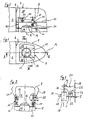
- Fig. 1
- in schematischer Darstellung einen vorderen Bereich eines Turms eines Unterseeboots gemäß der Erfindung in einer Draufsicht,
- Fig. 2
- den Bereich des Turms nach
Fig. 1 in einem Schnitt entlang der Schnittlinie II-II inFig. 1 , - Fig. 3
- den Bereich des Turms in einem Schnitt entlang der Schnittlinie III-III in
Fig. 1 und - Fig. 4
- eine Einzelheit X aus
Fig. 3 in vergrößerter Darstellung. - Im vorderen Bereich eines oberen Endes eines Turms 2 eines Unterseeboots gemäß der Erfindung ist ein Überwasserfahrstand 4 ausgebildet, der eine nach oben offene Brücke für die Überwasserfahrt des Unterseeboots bildet. Dieser Überwasserfahrstand 4 ist durch eine Wand 6, die den Überwasserfahrstand 4 gegenüber dem übrigen Turm 2 rückseitig abschließt sowie durch eine Seitenwand 8, die eine Brüstung des Überwasserfahrstands 4 bildet, begrenzt.
- Die Seitenwand 8 des Überwasserfahrstands 4 umgibt den Überwasserfahrstand 4 in Draufsicht im Wesentlichen U-förmig, wobei die oberen Enden der Seitenwand 8 derart in Richtung des Inneren des Überwasserfahrstands 4 gekrümmt sind, dass sie an der Oberseite des Überwasserfahrstands 4 eine im Wesentlichen rechteckige Öffnung 10 bilden. An seiner Unterseite wird der Überwasserfahrstand 4 durch ein Deck 12 begrenzt. Unterhalb dieses Decks 12 mündet ein Ausstiegsschacht 14, der einen Zugang von einem in den Zeichnungsfiguren nicht dargestellten Druckkörper des Unterseeboots zu dem Überwasserfahrstand 4 bildet.
- Der normalerweise vertikal ausgerichtete Ausstiegsschacht 14 bildet eine druckdicht verschließbare Schleuse. Hierzu sind sowohl an dem unteren Ende des Ausstiegsschachts 14 als auch an seinem oberen Ende druckdicht verschießbare Deckel 16 vorgesehen. Für den Fall einer Unterwasserhavarie des Unterseeboots bildet der Ausstiegsschacht 14 auch einen Notausstiegsschacht 14, über den die Besatzungsmitglieder das Unterseeboot im getauchten Zustand in speziellen Rettungsanzügen verlassen können. Hierbei bildet auch der Überwasserfahrstand 4 über dessen obere Öffnung 10 einen Teil des Notausstiegswegs. Zu diesem Zweck ist die Öffnung 10 des Überwasserfahrstands direkt oberhalb der von dem oberen Deckel 16 verschlossenen Ausstiegsluke des Notausstiegsschachts 14 angeordnet.
- Um einen Unterwassernotausstieg aus dem Unterseeboot zu erleichtern, sind Seitenwandteile 18 und 20, die einander gegenüberliegend im Wesentlichen parallel zu einer Längsachse A des Unterseeboots bzw. Turms 2 ausgerichtet sind, nach außen verschwenkbar. Indem die Seitenwandteile 18 und 20 um einen Winkel von zumindest 20° nach außen geschwenkt werden, wird die obere Öffnung 10 sowie der gesamte Innenraum des Überwasserfahrstands 4 erweitert und so der Notausstiegsfreiraum oberhalb des Notausstiegsschachts 14 bzw. innerhalb des Überwasserfahrstands 4 vergrößert. Hierdurch wird die Gefahr verringert, dass sich eine aus dem Notausstiegsschacht 14 aussteigende Person beim Aufstieg an die Wasseroberfläche innerhalb des Überwasserfahrstands 4 verfängt oder dort ihren Rettungsanzug beschädigt.
- Die Seitenwandteile 18 und 20 sind jeweils über zwei Gelenke 22 an dem Deck 12 des Überwasserfahrstands 4 angelenkt und so um eine Achse (
Fig. 4 ), die in einer Ebene quer zu einer Längsachse B des Notausstiegsschachts 14 angeordnet ist, schwenkbar. Die Anlenkung der Seitenwandteile 18 und 20 an den Gelenken 22 erfolgt über Hebel 24. Die Hebel 24 sind jeweils zweiarmig ausgebildet und weisen Hebelteile 26, 28 und 30 auf. Über die Hebelteile 26, die im Wesentlichen normal zu den Hebelteilen 28 und 30 ausgerichtet sind, erfolgt die Anlenkung der Hebel 24 an den Gelenken 22. Die Enden der Hebelteile 28, die in Richtung der Außenseite des Überwasserfahrstands 4 ausgerichtet sind, sind jeweils mit der Innenseite der Seitenwandteile 18 und 20 verbunden. Die Hebelteile 30 der Hebel 24 dienen jeweils zur Bewegungskopplung der Hebel 24 mit einem Hubzylinder oder einem manuellen Betätigungsmittel, mittels dessen die Seitenwandteile 18 und bzw. 20 nach außen verschwenkt werden können. - Die Seitenwandteile 18 und 20 sind jeweils über zwei Hebel 24 an zwei Gelenken 22 angelenkt. An dem Hebelteil 30 eines ersten Hebels 24 greift zum Verschwenken des Hebels 24 bzw. Seitenteils 18 oder 20 ein Kolben 32 einer Kolben-Zylinder-Anordnung 34 an. Die Kolben-Zylinder-Anordnung 34 ist pneumatisch über durch den Druckkörper des Unterseeboots gefüllte Druckluftleitungen 36 betätigbar. Der Zylinder 38 der Kolben-Zylinder-Anordnung 34 ist durch das Deck 12 des Überwasserfahrstands 4 geführt und unterhalb des Decks 12 an einem Gelenk 40 schwenkbar gelagert. An dem Hebelteil 30 eines zweiten Hebels 24 greift zum Verschwenken des Hebels 24 bzw. des Seitenteils 18 oder 20 ein durch den Druckkörper des Unterseeboots geführtes Gestänge 42 an. Dieses Gestänge 42 ist manuell betätigbar und für den Fall vorgesehen, dass die Kolben-Zylinder-Anordnung 34 aufgrund eines Defekts nicht betätigbar ist. Insofern schafft das Gestänge 42 eine Redundanz zu der Kolben-Zylinder-Anordnung 34, die sicherstellt, dass die Seitenwandteile 18 und 20 für einen Unterwassernotausstieg nach außen verschwenkt werden können.
- Im Fall eines Notausstiegs aus dem Unterseeboot steigen eine oder gegebenenfalls mehrere Personen in den Notausstiegsschacht 14, dessen druckkörperseitiger Deckel anschließend verschlossen wird. In dem Notausstiegsschacht 14 können die dort befindlichen Personen ihre Rettungsanzüge mittels hier vorgesehener Druckluftanschlüsse mit Luft füllen. Der Notausstiegsschacht 14 wird geflutet und ein Druckausgleich mit der Außenumgebung des Unterseeboots vorgenommen. Anschließend wird der obere Deckel 16 des Notausstiegsschachts 14 geöffnet. Bereits zuvor sind die Seitenwände 18 und 20 des Überwasserfahrstands 4 aus dem Inneren des Druckkörpers des Unterseeboots mittels der Kolben-Zylinder-Anordnungen 34 oder dem Gestänge 42 nach außen geschwenkt worden. Durch das Verschwenken der Seitenwandteile 18 und 20 wird der Notausstiegsfreiraum innerhalb des Überwasserfahrstands 4 deutlich vergrößert, was einen ungehinderten Aufstieg der das Unterseeboot über den Notausstiegsschacht 14 verlassenden Personen an die Wasseroberfläche gewährleistet. Insbesondere bei einer Schräglage des Unterseeboots wird auf diese Weise verhindert, dass sich Teile des Überwasserfahrstands 4, an denen sich eine aus dem Notausstiegsschacht 14 an die Wasseroberfläche aufschwimmenden Person ansonsten verfangen könnte, innerhalb des Aufschwimmwegs befinden.
-
- 2
- Turm
- 4
- Überwasserfahrstand
- 6
- Wand
- 8
- Seitenwand
- 10
- Öffnung
- 12
- Deck
- 14
- Ausstiegsschacht, Notausstiegsschacht
- 16
- Deckel
- 18
- Seitenwandteil
- 20
- Seitenwandteil
- 22
- Gelenk
- 24
- Hebel
- 26
- Hebelteil
- 28
- Hebelteil
- 30
- Hebelteil
- 32
- Kolben
- 34
- Kolben-Zylinder-Anordnung
- 36
- Druckluftleitung
- 38
- Zylinder
- 40
- Gelenk
- 42
- Gestänge
- A
- Längsachse
- B
- Längsachse
- C
- Achse
Claims (10)
- Unterseeboot mit einem Turm (2), an dem ein Überwasserfahrstand (4) ausgebildet ist, und mit einem im Bereich des Überwasserfahrstands (4) mündenden Notausstiegsschacht (14), dadurch gekennzeichnet, dass zumindest ein Teil (18, 20) einer den Überwasserfahrstand (4) begrenzenden Seitenwand (8) in eine Notausstiegsposition verbringbar ist, in der ein in Flucht zum Notausstiegsschacht (14) im Bereich des Überwasserfahrstands (4) gebildeter Notausstiegsfreiraum vergrößert ist.
- Unterseeboot nach Anspruch 1, dadurch gekennzeichnet, dass zwei in Längsrichtung des Unterseeboots einander im Wesentlichen gegenüberliegende Seitenwandteile (18, 20) nach außen bewegbar sind.
- Unterseeboot nach Anspruch 2, dadurch gekennzeichnet, dass die Seitenwandteile (18, 20) um eine in einer Ebene quer zu einer Längsachse (B) des Notausstiegsschachts (14) angeordnete Achse (C) schwenkbar sind.
- Unterseeboot nach einem Ansprüche 2 oder 3, dadurch gekennzeichnet, dass die Seitenwandteile (18, 20) zumindest um einen Winkel von 20° schwenkbar sind.
- Unterseeboot nach einem der Ansprüche 2 bis 4, dadurch gekennzeichnet, dass die Seitenwandteile (18, 20) an einem Deck (12) des Überwasserfahrstands (4) angelenkt sind.
- Unterseeboot nach Anspruch 5, dadurch gekennzeichnet, dass die Seitenwandteile (18, 20) jeweils über zumindest einen Hebel (24) am Deck (12) des Überwasserfahrstands (4) angelenkt sind.
- Unterseeboot nach Anspruch 6, dadurch gekennzeichnet, dass der Hebel (24) zumindest zweiarmig ausgebildet ist, wobei ein erster Hebelarm (28) mit dem Seitenwandteil (18, 20) verbunden ist und wobei an einem zweiten Hebelarm (30) ein Betätigungsmittel (34, 42) zum Verschwenken des Seitenwandteils ( 18, 20) angreift.
- Unterseeboot nach Anspruch 7, dadurch gekennzeichnet, dass der zweite Hebelarm (30) mit einer mit einem Druckmedium beaufschlagbaren Kolben-Zylinder-Anordnung (34) bewegungsgekoppelt ist.
- Unterseeboot nach Anspruch 7, dadurch gekennzeichnet, dass der zweite Hebelarm (30) mit einem manuell betätigbaren Betätigungsmittel (42) bewegungsgekoppelt ist.
- Unterseeboot nach einem der Ansprüche 7 bis 9, dadurch gekennzeichnet, dass das Seitenwandteil (18, 20) über zwei zumindest zweiarmige Hebel (24) am Deck (12) des Überwasserfahrstands (4) angelenkt ist, wobei die ersten Hebelarme (28) der beiden Hebel (24) mit dem Seitenwandteil (18, 20) verbunden sind und wobei der zweite Hebelarm (30) eines ersten Hebels (24) mit einem Kolben (32) einer bevorzugt pneumatisch betätigbaren Kolben-Zylinder-Anordnung (34) bewegungsgekoppelt ist und der zweite Hebelarm (30) eines zweiten Hebels (34) mit einem manuell betätigbaren Betätigungsmittels (42) bewegungsgekoppelt ist.
Applications Claiming Priority (1)
| Application Number | Priority Date | Filing Date | Title |
|---|---|---|---|
| DE200710035433 DE102007035433B3 (de) | 2007-07-28 | 2007-07-28 | Unterseeboot |
Publications (3)
| Publication Number | Publication Date |
|---|---|
| EP2020378A2 true EP2020378A2 (de) | 2009-02-04 |
| EP2020378A3 EP2020378A3 (de) | 2012-01-11 |
| EP2020378B1 EP2020378B1 (de) | 2012-07-25 |
Family
ID=39809876
Family Applications (1)
| Application Number | Title | Priority Date | Filing Date |
|---|---|---|---|
| EP20080009785 Active EP2020378B1 (de) | 2007-07-28 | 2008-05-29 | Unterseeboot |
Country Status (5)
| Country | Link |
|---|---|
| EP (1) | EP2020378B1 (de) |
| KR (1) | KR101032062B1 (de) |
| DE (1) | DE102007035433B3 (de) |
| ES (1) | ES2389993T3 (de) |
| PT (1) | PT2020378E (de) |
Families Citing this family (2)
| Publication number | Priority date | Publication date | Assignee | Title |
|---|---|---|---|---|
| DE102010048629B4 (de) * | 2010-10-15 | 2012-05-31 | Howaldtswerke-Deutsche Werft Gmbh | Unterseeboot |
| DE102018220268A1 (de) * | 2018-11-26 | 2020-05-28 | Thyssenkrupp Ag | Verfahren und Unterseeboot zur schnellen Ausbringung einer Gruppe von Tauchern unter Wasser |
Citations (2)
| Publication number | Priority date | Publication date | Assignee | Title |
|---|---|---|---|---|
| DE102005005119B3 (de) | 2005-02-04 | 2006-06-08 | Howaldtswerke-Deutsche Werft Gmbh | Unterseeboot mit einem Druckkörper |
| EP1767451A2 (de) | 2005-09-22 | 2007-03-28 | Howaldtswerke-Deutsche Werft GmbH | Unterseeboot |
Family Cites Families (2)
| Publication number | Priority date | Publication date | Assignee | Title |
|---|---|---|---|---|
| GB190904639A (en) * | 1909-02-25 | 1909-10-14 | Simon Lake | Improvements in Submarine or Submersible Vessels. |
| US2076219A (en) * | 1935-05-03 | 1937-04-06 | Belloni Angelo | Means for facilitating escape from submerged craft |
-
2007
- 2007-07-28 DE DE200710035433 patent/DE102007035433B3/de not_active Expired - Fee Related
-
2008
- 2008-05-29 EP EP20080009785 patent/EP2020378B1/de active Active
- 2008-05-29 ES ES08009785T patent/ES2389993T3/es active Active
- 2008-05-29 PT PT08009785T patent/PT2020378E/pt unknown
- 2008-07-02 KR KR1020080063842A patent/KR101032062B1/ko active IP Right Grant
Patent Citations (2)
| Publication number | Priority date | Publication date | Assignee | Title |
|---|---|---|---|---|
| DE102005005119B3 (de) | 2005-02-04 | 2006-06-08 | Howaldtswerke-Deutsche Werft Gmbh | Unterseeboot mit einem Druckkörper |
| EP1767451A2 (de) | 2005-09-22 | 2007-03-28 | Howaldtswerke-Deutsche Werft GmbH | Unterseeboot |
Also Published As
| Publication number | Publication date |
|---|---|
| KR20090012060A (ko) | 2009-02-02 |
| DE102007035433B3 (de) | 2008-11-06 |
| EP2020378A3 (de) | 2012-01-11 |
| EP2020378B1 (de) | 2012-07-25 |
| PT2020378E (pt) | 2012-09-26 |
| KR101032062B1 (ko) | 2011-05-02 |
| ES2389993T3 (es) | 2012-11-05 |
Similar Documents
| Publication | Publication Date | Title |
|---|---|---|
| EP1767451B1 (de) | Unterseeboot | |
| DE2744517C3 (de) | ölsammelschiff | |
| WO2019052801A1 (de) | Aussetz-system und aussetz-verfahren mit zusammenziehbarem vorleinenausleger | |
| EP2292508A2 (de) | Lukendeckel zum Abschließen einer Luke | |
| DE3716536A1 (de) | Unterseeboot | |
| DE10310901A1 (de) | Unterseeboot | |
| CH700563A2 (de) | Tenderlift für Wasserfahrzeuge. | |
| EP2020378B1 (de) | Unterseeboot | |
| DE3834174C2 (de) | ||
| DE2926465A1 (de) | Einrichtung zum be- und entladen von schiffsladungen | |
| EP1688347B1 (de) | Unterseeboot mit einem speziellen Schacht | |
| DE3534257C2 (de) | Schwenkbar angeordnete Ablaufbahn für Freifallboote auf Schiffen | |
| WO1997006051A1 (de) | Verfahren zum betreiben eines segelschiffes und segelschiff | |
| DE2846154C2 (de) | Doppelrumpf-Wasserfahrzeug mit Taucherausstiegskammer | |
| DE102014016152B4 (de) | Vorrichtung zum Ausbringen oder Aufnehmen von Personen und schwimmfähigen Objekten | |
| DE4209090A1 (de) | Plattform fuer vorzugsweise jachten | |
| EP2065302B1 (de) | Unterseeboot mit Notausstiegsluk | |
| DE3704343A1 (de) | Verfahren und einrichtung zum ein- und ausladen von torpedos | |
| EP3129318B1 (de) | Hubvorrichtung für ein u-boot | |
| DE1931916B2 (de) | Kugelförmige Rettungsboje | |
| DE3733993C2 (de) | ||
| DE2533600B2 (de) | Wasserfahrzeug zum Aufnehmen eines schwimmenden Gegenstandes | |
| WO2023180411A1 (de) | Rettungs-bordwand | |
| DE102017109641B4 (de) | Tender | |
| DE4238786A1 (de) | Takelung für Wasserfahrzeuge mit Drehmomentkompensation |
Legal Events
| Date | Code | Title | Description |
|---|---|---|---|
| PUAI | Public reference made under article 153(3) epc to a published international application that has entered the european phase |
Free format text: ORIGINAL CODE: 0009012 |
|
| AK | Designated contracting states |
Kind code of ref document: A2 Designated state(s): AT BE BG CH CY CZ DE DK EE ES FI FR GB GR HR HU IE IS IT LI LT LU LV MC MT NL NO PL PT RO SE SI SK TR |
|
| AX | Request for extension of the european patent |
Extension state: AL BA MK RS |
|
| REG | Reference to a national code |
Ref country code: DE Ref legal event code: R079 Ref document number: 502008007752 Country of ref document: DE Free format text: PREVIOUS MAIN CLASS: B63G0008060000 Ipc: B63G0008400000 |
|
| PUAL | Search report despatched |
Free format text: ORIGINAL CODE: 0009013 |
|
| AK | Designated contracting states |
Kind code of ref document: A3 Designated state(s): AT BE BG CH CY CZ DE DK EE ES FI FR GB GR HR HU IE IS IT LI LT LU LV MC MT NL NO PL PT RO SE SI SK TR |
|
| AX | Request for extension of the european patent |
Extension state: AL BA MK RS |
|
| RIC1 | Information provided on ipc code assigned before grant |
Ipc: B63G 8/40 20060101AFI20111202BHEP Ipc: B63G 8/06 20060101ALI20111202BHEP |
|
| GRAP | Despatch of communication of intention to grant a patent |
Free format text: ORIGINAL CODE: EPIDOSNIGR1 |
|
| 17P | Request for examination filed |
Effective date: 20120126 |
|
| GRAS | Grant fee paid |
Free format text: ORIGINAL CODE: EPIDOSNIGR3 |
|
| GRAA | (expected) grant |
Free format text: ORIGINAL CODE: 0009210 |
|
| AK | Designated contracting states |
Kind code of ref document: B1 Designated state(s): AT BE BG CH CY CZ DE DK EE ES FI FR GB GR HR HU IE IS IT LI LT LU LV MC MT NL NO PL PT RO SE SI SK TR |
|
| REG | Reference to a national code |
Ref country code: GB Ref legal event code: FG4D Free format text: NOT ENGLISH |
|
| REG | Reference to a national code |
Ref country code: CH Ref legal event code: EP |
|
| REG | Reference to a national code |
Ref country code: AT Ref legal event code: REF Ref document number: 567583 Country of ref document: AT Kind code of ref document: T Effective date: 20120815 Ref country code: IE Ref legal event code: FG4D Free format text: LANGUAGE OF EP DOCUMENT: GERMAN |
|
| AKX | Designation fees paid |
Designated state(s): AT BE BG CH CY CZ DE DK EE ES FI FR GB GR HR HU IE IS IT LI LT LU LV MC MT NL NO PL PT RO SE SI SK TR |
|
| REG | Reference to a national code |
Ref country code: DE Ref legal event code: R096 Ref document number: 502008007752 Country of ref document: DE Effective date: 20120920 |
|
| REG | Reference to a national code |
Ref country code: PT Ref legal event code: SC4A Free format text: AVAILABILITY OF NATIONAL TRANSLATION Effective date: 20120920 |
|
| REG | Reference to a national code |
Ref country code: GR Ref legal event code: EP Ref document number: 20120402099 Country of ref document: GR Effective date: 20120915 |
|
| REG | Reference to a national code |
Ref country code: ES Ref legal event code: FG2A Ref document number: 2389993 Country of ref document: ES Kind code of ref document: T3 Effective date: 20121105 |
|
| REG | Reference to a national code |
Ref country code: SE Ref legal event code: TRGR |
|
| REG | Reference to a national code |
Ref country code: NL Ref legal event code: T3 |
|
| REG | Reference to a national code |
Ref country code: LT Ref legal event code: MG4D Effective date: 20120725 |
|
| PG25 | Lapsed in a contracting state [announced via postgrant information from national office to epo] |
Ref country code: IS Free format text: LAPSE BECAUSE OF FAILURE TO SUBMIT A TRANSLATION OF THE DESCRIPTION OR TO PAY THE FEE WITHIN THE PRESCRIBED TIME-LIMIT Effective date: 20121125 Ref country code: NO Free format text: LAPSE BECAUSE OF FAILURE TO SUBMIT A TRANSLATION OF THE DESCRIPTION OR TO PAY THE FEE WITHIN THE PRESCRIBED TIME-LIMIT Effective date: 20121025 Ref country code: FI Free format text: LAPSE BECAUSE OF FAILURE TO SUBMIT A TRANSLATION OF THE DESCRIPTION OR TO PAY THE FEE WITHIN THE PRESCRIBED TIME-LIMIT Effective date: 20120725 Ref country code: CY Free format text: LAPSE BECAUSE OF FAILURE TO SUBMIT A TRANSLATION OF THE DESCRIPTION OR TO PAY THE FEE WITHIN THE PRESCRIBED TIME-LIMIT Effective date: 20120725 Ref country code: LT Free format text: LAPSE BECAUSE OF FAILURE TO SUBMIT A TRANSLATION OF THE DESCRIPTION OR TO PAY THE FEE WITHIN THE PRESCRIBED TIME-LIMIT Effective date: 20120725 Ref country code: HR Free format text: LAPSE BECAUSE OF FAILURE TO SUBMIT A TRANSLATION OF THE DESCRIPTION OR TO PAY THE FEE WITHIN THE PRESCRIBED TIME-LIMIT Effective date: 20120725 |
|
| REG | Reference to a national code |
Ref country code: DE Ref legal event code: R082 Ref document number: 502008007752 Country of ref document: DE Representative=s name: PATENTANWAELTE VOLLMANN & HEMMER, DE |
|
| PG25 | Lapsed in a contracting state [announced via postgrant information from national office to epo] |
Ref country code: SI Free format text: LAPSE BECAUSE OF FAILURE TO SUBMIT A TRANSLATION OF THE DESCRIPTION OR TO PAY THE FEE WITHIN THE PRESCRIBED TIME-LIMIT Effective date: 20120725 Ref country code: PL Free format text: LAPSE BECAUSE OF FAILURE TO SUBMIT A TRANSLATION OF THE DESCRIPTION OR TO PAY THE FEE WITHIN THE PRESCRIBED TIME-LIMIT Effective date: 20120725 Ref country code: LV Free format text: LAPSE BECAUSE OF FAILURE TO SUBMIT A TRANSLATION OF THE DESCRIPTION OR TO PAY THE FEE WITHIN THE PRESCRIBED TIME-LIMIT Effective date: 20120725 |
|
| RAP2 | Party data changed (patent owner data changed or rights of a patent transferred) |
Owner name: THYSSENKRUPP MARINE SYSTEMS GMBH |
|
| REG | Reference to a national code |
Ref country code: NL Ref legal event code: SD Effective date: 20130312 |
|
| REG | Reference to a national code |
Ref country code: DE Ref legal event code: R082 Ref document number: 502008007752 Country of ref document: DE Representative=s name: PATENTANWAELTE VOLLMANN & HEMMER, DE Effective date: 20130206 Ref country code: DE Ref legal event code: R082 Ref document number: 502008007752 Country of ref document: DE Effective date: 20130206 Ref country code: DE Ref legal event code: R081 Ref document number: 502008007752 Country of ref document: DE Owner name: THYSSENKRUPP MARINE SYSTEMS GMBH, DE Free format text: FORMER OWNER: HOWALDTSWERKE-DEUTSCHE WERFT GMBH, 24143 KIEL, DE Effective date: 20130206 |
|
| REG | Reference to a national code |
Ref country code: FR Ref legal event code: CD Owner name: THYSSENKRUPP MARINE SYSTEMS GMBH Effective date: 20130313 |
|
| REG | Reference to a national code |
Ref country code: NL Ref legal event code: TD Effective date: 20130417 |
|
| PG25 | Lapsed in a contracting state [announced via postgrant information from national office to epo] |
Ref country code: EE Free format text: LAPSE BECAUSE OF FAILURE TO SUBMIT A TRANSLATION OF THE DESCRIPTION OR TO PAY THE FEE WITHIN THE PRESCRIBED TIME-LIMIT Effective date: 20120725 Ref country code: DK Free format text: LAPSE BECAUSE OF FAILURE TO SUBMIT A TRANSLATION OF THE DESCRIPTION OR TO PAY THE FEE WITHIN THE PRESCRIBED TIME-LIMIT Effective date: 20120725 Ref country code: RO Free format text: LAPSE BECAUSE OF FAILURE TO SUBMIT A TRANSLATION OF THE DESCRIPTION OR TO PAY THE FEE WITHIN THE PRESCRIBED TIME-LIMIT Effective date: 20120725 Ref country code: CZ Free format text: LAPSE BECAUSE OF FAILURE TO SUBMIT A TRANSLATION OF THE DESCRIPTION OR TO PAY THE FEE WITHIN THE PRESCRIBED TIME-LIMIT Effective date: 20120725 |
|
| PGFP | Annual fee paid to national office [announced via postgrant information from national office to epo] |
Ref country code: ES Payment date: 20130320 Year of fee payment: 6 Ref country code: FR Payment date: 20130409 Year of fee payment: 6 |
|
| PG25 | Lapsed in a contracting state [announced via postgrant information from national office to epo] |
Ref country code: SK Free format text: LAPSE BECAUSE OF FAILURE TO SUBMIT A TRANSLATION OF THE DESCRIPTION OR TO PAY THE FEE WITHIN THE PRESCRIBED TIME-LIMIT Effective date: 20120725 |
|
| PGFP | Annual fee paid to national office [announced via postgrant information from national office to epo] |
Ref country code: GR Payment date: 20130328 Year of fee payment: 6 |
|
| PLBE | No opposition filed within time limit |
Free format text: ORIGINAL CODE: 0009261 |
|
| STAA | Information on the status of an ep patent application or granted ep patent |
Free format text: STATUS: NO OPPOSITION FILED WITHIN TIME LIMIT |
|
| PGFP | Annual fee paid to national office [announced via postgrant information from national office to epo] |
Ref country code: PT Payment date: 20130312 Year of fee payment: 6 |
|
| 26N | No opposition filed |
Effective date: 20130426 |
|
| PG25 | Lapsed in a contracting state [announced via postgrant information from national office to epo] |
Ref country code: BG Free format text: LAPSE BECAUSE OF FAILURE TO SUBMIT A TRANSLATION OF THE DESCRIPTION OR TO PAY THE FEE WITHIN THE PRESCRIBED TIME-LIMIT Effective date: 20121025 |
|
| PGFP | Annual fee paid to national office [announced via postgrant information from national office to epo] |
Ref country code: GB Payment date: 20130429 Year of fee payment: 6 Ref country code: SE Payment date: 20130513 Year of fee payment: 6 |
|
| REG | Reference to a national code |
Ref country code: DE Ref legal event code: R097 Ref document number: 502008007752 Country of ref document: DE Effective date: 20130426 |
|
| PGFP | Annual fee paid to national office [announced via postgrant information from national office to epo] |
Ref country code: NL Payment date: 20130513 Year of fee payment: 6 |
|
| BERE | Be: lapsed |
Owner name: HOWALDTSWERKE-DEUTSCHE WERFT G.M.B.H. Effective date: 20130531 |
|
| PG25 | Lapsed in a contracting state [announced via postgrant information from national office to epo] |
Ref country code: MC Free format text: LAPSE BECAUSE OF FAILURE TO SUBMIT A TRANSLATION OF THE DESCRIPTION OR TO PAY THE FEE WITHIN THE PRESCRIBED TIME-LIMIT Effective date: 20120725 |
|
| REG | Reference to a national code |
Ref country code: CH Ref legal event code: PL |
|
| PG25 | Lapsed in a contracting state [announced via postgrant information from national office to epo] |
Ref country code: LI Free format text: LAPSE BECAUSE OF NON-PAYMENT OF DUE FEES Effective date: 20130531 Ref country code: CH Free format text: LAPSE BECAUSE OF NON-PAYMENT OF DUE FEES Effective date: 20130531 |
|
| REG | Reference to a national code |
Ref country code: IE Ref legal event code: MM4A |
|
| PG25 | Lapsed in a contracting state [announced via postgrant information from national office to epo] |
Ref country code: BE Free format text: LAPSE BECAUSE OF NON-PAYMENT OF DUE FEES Effective date: 20130531 |
|
| PG25 | Lapsed in a contracting state [announced via postgrant information from national office to epo] |
Ref country code: IE Free format text: LAPSE BECAUSE OF NON-PAYMENT OF DUE FEES Effective date: 20130529 |
|
| REG | Reference to a national code |
Ref country code: AT Ref legal event code: MM01 Ref document number: 567583 Country of ref document: AT Kind code of ref document: T Effective date: 20130529 |
|
| PG25 | Lapsed in a contracting state [announced via postgrant information from national office to epo] |
Ref country code: AT Free format text: LAPSE BECAUSE OF NON-PAYMENT OF DUE FEES Effective date: 20130529 |
|
| REG | Reference to a national code |
Ref country code: PT Ref legal event code: MM4A Free format text: LAPSE DUE TO NON-PAYMENT OF FEES Effective date: 20141202 |
|
| REG | Reference to a national code |
Ref country code: NL Ref legal event code: V1 Effective date: 20141201 |
|
| GBPC | Gb: european patent ceased through non-payment of renewal fee |
Effective date: 20140529 |
|
| PG25 | Lapsed in a contracting state [announced via postgrant information from national office to epo] |
Ref country code: PT Free format text: LAPSE BECAUSE OF NON-PAYMENT OF DUE FEES Effective date: 20141202 Ref country code: GR Free format text: LAPSE BECAUSE OF NON-PAYMENT OF DUE FEES Effective date: 20141203 Ref country code: SE Free format text: LAPSE BECAUSE OF NON-PAYMENT OF DUE FEES Effective date: 20140530 |
|
| REG | Reference to a national code |
Ref country code: GR Ref legal event code: ML Ref document number: 20120402099 Country of ref document: GR Effective date: 20141203 |
|
| REG | Reference to a national code |
Ref country code: DE Ref legal event code: R084 Ref document number: 502008007752 Country of ref document: DE |
|
| REG | Reference to a national code |
Ref country code: SE Ref legal event code: EUG |
|
| PG25 | Lapsed in a contracting state [announced via postgrant information from national office to epo] |
Ref country code: MT Free format text: LAPSE BECAUSE OF FAILURE TO SUBMIT A TRANSLATION OF THE DESCRIPTION OR TO PAY THE FEE WITHIN THE PRESCRIBED TIME-LIMIT Effective date: 20120725 Ref country code: NL Free format text: LAPSE BECAUSE OF NON-PAYMENT OF DUE FEES Effective date: 20141201 |
|
| REG | Reference to a national code |
Ref country code: FR Ref legal event code: ST Effective date: 20150130 |
|
| REG | Reference to a national code |
Ref country code: DE Ref legal event code: R084 Ref document number: 502008007752 Country of ref document: DE Effective date: 20150206 |
|
| PG25 | Lapsed in a contracting state [announced via postgrant information from national office to epo] |
Ref country code: IT Free format text: LAPSE BECAUSE OF NON-PAYMENT OF DUE FEES Effective date: 20140529 |
|
| PG25 | Lapsed in a contracting state [announced via postgrant information from national office to epo] |
Ref country code: GB Free format text: LAPSE BECAUSE OF NON-PAYMENT OF DUE FEES Effective date: 20140529 Ref country code: FR Free format text: LAPSE BECAUSE OF NON-PAYMENT OF DUE FEES Effective date: 20140602 |
|
| PG25 | Lapsed in a contracting state [announced via postgrant information from national office to epo] |
Ref country code: HU Free format text: LAPSE BECAUSE OF FAILURE TO SUBMIT A TRANSLATION OF THE DESCRIPTION OR TO PAY THE FEE WITHIN THE PRESCRIBED TIME-LIMIT; INVALID AB INITIO Effective date: 20080529 Ref country code: LU Free format text: LAPSE BECAUSE OF NON-PAYMENT OF DUE FEES Effective date: 20130529 |
|
| REG | Reference to a national code |
Ref country code: DE Ref legal event code: R082 Ref document number: 502008007752 Country of ref document: DE |
|
| REG | Reference to a national code |
Ref country code: ES Ref legal event code: FD2A Effective date: 20151030 |
|
| PG25 | Lapsed in a contracting state [announced via postgrant information from national office to epo] |
Ref country code: ES Free format text: LAPSE BECAUSE OF NON-PAYMENT OF DUE FEES Effective date: 20140530 |
|
| PG25 | Lapsed in a contracting state [announced via postgrant information from national office to epo] |
Ref country code: TR Free format text: LAPSE BECAUSE OF NON-PAYMENT OF DUE FEES Effective date: 20140529 |
|
| REG | Reference to a national code |
Ref country code: DE Ref legal event code: R081 Ref document number: 502008007752 Country of ref document: DE Owner name: THYSSENKRUPP MARINE SYSTEMS GMBH, DE Free format text: FORMER OWNER: THYSSENKRUPP MARINE SYSTEMS GMBH, 24143 KIEL, DE |
|
| P01 | Opt-out of the competence of the unified patent court (upc) registered |
Effective date: 20230530 |
|
| PGFP | Annual fee paid to national office [announced via postgrant information from national office to epo] |
Ref country code: DE Payment date: 20220801 Year of fee payment: 16 |