EP2020331A1 - Vorrichtung und Verfahren zur Führung eines Fahrzeugs - Google Patents
Vorrichtung und Verfahren zur Führung eines Fahrzeugs Download PDFInfo
- Publication number
- EP2020331A1 EP2020331A1 EP20080013195 EP08013195A EP2020331A1 EP 2020331 A1 EP2020331 A1 EP 2020331A1 EP 20080013195 EP20080013195 EP 20080013195 EP 08013195 A EP08013195 A EP 08013195A EP 2020331 A1 EP2020331 A1 EP 2020331A1
- Authority
- EP
- European Patent Office
- Prior art keywords
- vehicle speed
- limited
- speed
- limit
- vehicle
- Prior art date
- Legal status (The legal status is an assumption and is not a legal conclusion. Google has not performed a legal analysis and makes no representation as to the accuracy of the status listed.)
- Granted
Links
Images



Classifications
-
- B—PERFORMING OPERATIONS; TRANSPORTING
- B60—VEHICLES IN GENERAL
- B60W—CONJOINT CONTROL OF VEHICLE SUB-UNITS OF DIFFERENT TYPE OR DIFFERENT FUNCTION; CONTROL SYSTEMS SPECIALLY ADAPTED FOR HYBRID VEHICLES; ROAD VEHICLE DRIVE CONTROL SYSTEMS FOR PURPOSES NOT RELATED TO THE CONTROL OF A PARTICULAR SUB-UNIT
- B60W30/00—Purposes of road vehicle drive control systems not related to the control of a particular sub-unit, e.g. of systems using conjoint control of vehicle sub-units
- B60W30/14—Adaptive cruise control
- B60W30/143—Speed control
- B60W30/146—Speed limiting
-
- B—PERFORMING OPERATIONS; TRANSPORTING
- B60—VEHICLES IN GENERAL
- B60W—CONJOINT CONTROL OF VEHICLE SUB-UNITS OF DIFFERENT TYPE OR DIFFERENT FUNCTION; CONTROL SYSTEMS SPECIALLY ADAPTED FOR HYBRID VEHICLES; ROAD VEHICLE DRIVE CONTROL SYSTEMS FOR PURPOSES NOT RELATED TO THE CONTROL OF A PARTICULAR SUB-UNIT
- B60W50/00—Details of control systems for road vehicle drive control not related to the control of a particular sub-unit, e.g. process diagnostic or vehicle driver interfaces
- B60W50/08—Interaction between the driver and the control system
- B60W50/14—Means for informing the driver, warning the driver or prompting a driver intervention
-
- B—PERFORMING OPERATIONS; TRANSPORTING
- B60—VEHICLES IN GENERAL
- B60W—CONJOINT CONTROL OF VEHICLE SUB-UNITS OF DIFFERENT TYPE OR DIFFERENT FUNCTION; CONTROL SYSTEMS SPECIALLY ADAPTED FOR HYBRID VEHICLES; ROAD VEHICLE DRIVE CONTROL SYSTEMS FOR PURPOSES NOT RELATED TO THE CONTROL OF A PARTICULAR SUB-UNIT
- B60W2555/00—Input parameters relating to exterior conditions, not covered by groups B60W2552/00, B60W2554/00
- B60W2555/60—Traffic rules, e.g. speed limits or right of way
-
- B—PERFORMING OPERATIONS; TRANSPORTING
- B60—VEHICLES IN GENERAL
- B60W—CONJOINT CONTROL OF VEHICLE SUB-UNITS OF DIFFERENT TYPE OR DIFFERENT FUNCTION; CONTROL SYSTEMS SPECIALLY ADAPTED FOR HYBRID VEHICLES; ROAD VEHICLE DRIVE CONTROL SYSTEMS FOR PURPOSES NOT RELATED TO THE CONTROL OF A PARTICULAR SUB-UNIT
- B60W2556/00—Input parameters relating to data
- B60W2556/45—External transmission of data to or from the vehicle
- B60W2556/50—External transmission of data to or from the vehicle of positioning data, e.g. GPS [Global Positioning System] data
Definitions
- the present invention relates to an apparatus for and a method of controlling traveling of a vehicle, which is configured to control a travel speed of a host vehicle, based on a set vehicle speed and/or a limited vehicle speed of the host vehicle's driving lane, which limited vehicle speed is obtained as navigation information.
- JP2006-321354 discloses various adaptive cruise control (ACC) technologies.
- ACC adaptive cruise control
- the adaptive cruise traveling control system disclosed in JP2006-321354 is configured to execute three different traveling control functions, that is, (i) a first traveling control function (i.e., a cruise control function, namely, cruise-set-speed control at a set vehicle speed set by the driver), (ii) a second traveling control function (i.e., a so-called “following control” that a host vehicle follows a preceding vehicle, while keeping the host vehicle's distance from the preceding vehicle at an approximately constant vehicle-to-vehicle distance, and (iii) a third traveling control function that adjusts the host vehicle speed to an appropriate speed based on road information (in particular, limited vehicle speed information) from a navigation device).
- a first traveling control function i.e., a cruise control function, namely, cruise-set-speed control at a set vehicle speed set by the driver
- a second traveling control function i.
- the adaptive cruise traveling control system disclosed in JP2006-321354 informs the driver about "overspeed” (the set vehicle speed exceeding the limited vehicle speed). If the driver does not change the set vehicle speed for a predetermined elapsed time, measured from the point of time when the "overspeed" information has been outputted to the driver, then the adaptive cruise traveling control system automatically changes the set vehicle speed to the limited vehicle speed, without driver intervention.
- the cruise traveling control system disclosed in JP2006-321354 requires the aforementioned predetermined elapsed time (i.e., a constant delay time or a constant waiting time, measured from the point of time when the set vehicle speed has exceeded the limited vehicle speed), until an automatic change from set vehicle speed to limited vehicle speed occurs.
- a constant delay time a constant waiting time
- the conventional adaptive cruise traveling control system automatically sets the set vehicle speed to the erroneously-detected limited vehicle speed, regardless of a driver's wishes.
- Such an automatic change from set vehicle speed to limited vehicle speed, initiated due to the erroneous input information would also be likely to cause the driver to feel discomfort.
- an adaptive cruise control (ACC) system permits an ACC vehicle, often called “host vehicle”, to travel at a limited vehicle speed, in accord with a driver's wishes.
- an object of the invention to provide an apparatus for and a method of controlling traveling of a host vehicle, which is configured to permit the host vehicle to travel at a limited vehicle speed, in accord with a driver's wishes.
- an apparatus for controlling traveling of a vehicle comprises a set vehicle speed detector configured to detect a set vehicle speed, a limited vehicle speed detector configured to detect a limited vehicle speed of a road, on which a host vehicle is traveling, a man-machine interface configured to set a desired vehicle speed by a driver's operation made to the man-machine interface, which operation is detected by a driver's operation detector configured to detect the driver's operation made to the man-machine interface, a desired vehicle speed setting section configured to set a determined desired vehicle speed based on the set vehicle speed, the limited vehicle speed, and the desired vehicle speed, and a control device configured to control a speed of the host vehicle in a manner so as to bring the host vehicle speed closer to the determined desired vehicle speed.
- an apparatus for controlling traveling of a vehicle comprises a set vehicle speed detector configured to detect a set vehicle speed, a limited vehicle speed detector configured to detect a limited vehicle speed of a road, on which a host vehicle is traveling, a man-machine interface configured to set a desired vehicle speed to the limited vehicle speed manually by a driver's operation made to the man-machine interface, a driver's operation detector configured to detect the driver's operation made to the man-machine interface, a desired vehicle speed setting section configured to set the desired vehicle speed basically to the set vehicle speed, and also configured to set the desired vehicle speed to the limited vehicle speed, based on a result of detection of the driver's operation made to the man-machine interface, under a condition where the limited vehicle speed has been detected by the limited vehicle speed detector, and a control device configured to control a speed of the host vehicle in a manner so as to bring the host vehicle speed closer to the desired vehicle speed.
- a method of controlling traveling of a vehicle comprises controlling a speed of a host vehicle at a first speed-control mode at which a set vehicle speed is set as a desired vehicle speed, and controlling the host vehicle speed at a second speed-control mode at which a limited vehicle speed of a road, on which the host vehicle is traveling, is set as the desired vehicle speed, when the desired vehicle speed has been set to the limited vehicle speed manually by a driver's operation made to a man-machine interface, under a condition where the limited vehicle speed has been detected.
- the adaptive cruise traveling control (ACC) system configuration of the first embodiment is exemplified in a rear-wheel-drive, four-wheeled automotive vehicle.
- the ACC system of the first embodiment is provided with a global positioning system (GPS) 1, a course estimation section 2, an acceleration/deceleration control device 3, a host vehicle speed acquisition section 10, a navigation device 20, a preceding vehicle information acquisition section 30, and a cruise vehicle speed setting section 40.
- GPS global positioning system
- Host vehicle speed acquisition section 10 includes a wheel speed sensor 11 and a host vehicle speed calculation section 12. Wheel speed sensor 11 is provided for detecting the speed of each wheel on the vehicle. Host vehicle speed calculation section 12 calculates a travel speed of a host vehicle (i.e., host vehicle speed, denoted by "V") based on the wheel speed signal from wheel speed sensor 11. Host vehicle speed calculation section 12 outputs a signal indicative of the calculated host vehicle speed to each of course estimation section 2, acceleration/deceleration control device 3, and cruise vehicle speed setting section 40, exactly, a cruise vehicle speed setting processing section 43 (described later).
- V travel speed of a host vehicle
- Host vehicle speed calculation section 12 outputs a signal indicative of the calculated host vehicle speed to each of course estimation section 2, acceleration/deceleration control device 3, and cruise vehicle speed setting section 40, exactly, a cruise vehicle speed setting processing section 43 (described later).
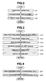
- Fig. 2 there is shown the procedure executed within host vehicle speed acquisition section 10.
- the host vehicle speed arithmetic processing shown in Fig. 2 is executed as time-triggered interrupt routines to be triggered every predetermined sampling time intervals such as 10 milliseconds.
- step S1 host vehicle speed calculation section 12 reads wheel speeds detected by wheel speed sensor 11. For instance, in the case of the rear-wheel-drive vehicle, input information about front-left and front-right wheel speeds Vw1 and Vw2 are read.
- host vehicle speed calculation section 12 calculates host vehicle speed V based on the wheel-speed information data signals read through step S1. For instance, in the case of the rear-wheel-drive vehicle, host vehicle speed V is arithmetically calculated as a simple average of front wheel speeds Vw1 and Vw2 from the following equation (1).
- V Vw ⁇ 1 + Vw ⁇ 2 / 2
- host vehicle speed calculation section 12 outputs a signal indicative of host vehicle speed V (calculated through step S2) to each of course estimation section 2, acceleration/deceleration control device 3, and cruise vehicle speed setting section 40 (exactly, cruise vehicle speed setting processing section 43).
- Navigation device 20 stores a map database (DB) 21 and also includes a road information acquisition section 22, a preview data origination section 23, and an adaptive-cruise-traveling-control desired vehicle speed calculation section (simply, an ACC desired vehicle speed calculation section) 24.
- Road information acquisition section 22 is configured to estimate or specify a position of the host vehicle on the map data, based on the electric map data retrieved from map database 21, the positional information of the host vehicle, detected by means of GPS 1, and the wheel-speed sensor signals from wheel speed sensor 11.
- Road information acquisition section 22 is further configured to acquire, based on both the map data retrieved from map database 21 and the specified position of the host vehicle on the map data, road information about a road ahead of the host vehicle and also including the currently-specified host vehicle's position, as preview information. Thereafter, road information acquisition section 22 outputs the acquired preview information to preview data origination section 23.
- Preview data origination section 23 is configured to detect, based on the preview information obtained through road information acquisition section 22, forward road information, concretely, a road classification, coordinates of nodes, a link classification, a road width, the number of lanes, the presence or absence of a branch node, guidepath information, a limited vehicle speed, denoted by "V LIMIT ", and the like.
- Preview data origination section 23 originates, based on the detected forward road information, a preview data in a predetermined format.
- Preview data origination section 23 outputs the originated preview data to each of ACC desired vehicle speed calculation section 24 and course estimation section 2.
- ACC desired vehicle speed calculation section 24 calculates, based on the preview data originated by preview data origination section 23, an adaptive-cruise-traveling-control desired vehicle speed (simply, an ACC desired vehicle speed, denoted by "V T ", more simply, a desired vehicle speed) at each of points within the originated preview.
- ACC desired vehicle speed calculation section 24 outputs the calculated ACC desired vehicle speed to each of course estimation section 2, acceleration/deceleration control device 3, and cruise vehicle speed setting section 40 (exactly, cruise vehicle speed setting processing section 43).
- Navigation device 20 outputs various information, containing the calculated ACC desired vehicle speed, to each of course estimation section 2, acceleration/deceleration control device 3, and cruise vehicle speed setting section 40 (exactly, cruise vehicle speed setting processing section 43).
- Fig. 3 there is shown the procedure executed within navigation device 20.
- the preview data origination processing shown in Fig. 3 is also executed as time-triggered interrupt routines to be triggered every predetermined sampling time intervals.
- road information acquisition section 22 reads positional information of the host vehicle. More concretely, road information acquisition section 22 reads latitude-and-longitude information of the host vehicle detected by use of GPS 1.
- road information acquisition section 22 reads wheel speeds. Concretely, input information about wheel-speed signals generated from wheel-speed sensor 11 is read.
- road information acquisition section 22 reads the electronic map data. Concretely, road information acquisition section 22 reads or retrieves the map data in a constant distance range from the host vehicle, from map database 21.
- road information acquisition section 22 estimates or specifies a position of the host vehicle. Concretely, road information acquisition section 22 estimates or specifies a position of the host vehicle, based on the latitude-and-longitude information of the host vehicle (read through step S11), the wheel-speed information (read through step S12), and the map data (read through step S13).
- preview data origination section 23 originates a preview data.
- preview data origination section 23 detects, based on the map data (read through step S13) and the positional information of the host vehicle (estimated through step S14), forward road information in a predetermined range from the currently-specified host vehicle's position to a constant distance L ahead of the currently-specified host vehicle's position, and then originates a preview data concerning the forward road information about a road in front of the host vehicle and also including the currently-specified host vehicle's position.
- preview data origination section 23 detects a road classification, a branching-off angle, a distance to a branch node, GPS information, a node classification, a transitional distance between the currently-specified host vehicle's position and the node, limited vehicle speed V LIMIT , coordinates of nodes, a link classification, a link angle, the number of branches, and a linked relation between a certain node and another node. Thereafter, preview data origination section 23 originates, based on the detected forward road information, a preview data in a predetermined format.
- preview data origination section 23 outputs the preview data (originated through step S15) to each of ACC desired vehicle speed calculation section 24 and course estimation section 2.
- navigation device 20 originates a preview data, based on the map data and the host vehicle's positional information, and then outputs the originated preview data to each of ACC desired vehicle speed calculation section 24 and course estimation section 2. Additionally, navigation device 20 outputs various information, which information contains information about ACC desired vehicle speed V T at each of points within the originated preview, calculated based on the originated preview data by means of ACC desired vehicle speed calculation section 24, to each of course estimation section 2, acceleration/deceleration control device 3, and cruise vehicle speed setting section 40 (exactly, cruise vehicle speed setting processing section 43).
- Preceding vehicle information acquisition section 30 includes a laser radar (exactly, a scanning laser radar sensor) 31 and a preceding vehicle information processing section 32.
- Preceding vehicle information acquisition section 30 is configured to detect a preceding vehicle, based on an output signal from laser radar 31.
- preceding vehicle information processing section 32 is further configured to calculate the host vehicle's distance from the detected preceding vehicle, often called an "inter-vehicle distance" or a "vehicle-to-vehicle distance", and a difference (that is, a relative speed) between the host vehicle speed and the preceding vehicle speed.
- Preceding vehicle information acquisition section 30 outputs information about the calculated vehicle-to-vehicle distance and the calculated relative speed to each of course estimation section 2 and acceleration/deceleration control device 3.
- Fig. 4 there is shown the procedure executed within preceding vehicle information acquisition section 30.
- the preceding vehicle information processing shown in Fig. 4 is executed as time-triggered interrupt routines to be triggered every predetermined sampling time intervals.
- preceding vehicle information processing section 32 obtains preceding vehicle information, based on an output signal from laser radar 31. Concretely, as the preceding vehicle information concerning the preceding vehicle traveling on the same lane as the host vehicle, preceding vehicle information processing section 32 obtains a preceding vehicle acquisition flag, a preceding vehicle speed Vf, a speed difference Vd between the host vehicle speed V and the preceding vehicle speed Vf, and a vehicle-to-vehicle distance D between the preceding vehicle and the host vehicle.
- preceding vehicle information processing section 32 outputs the preceding vehicle information about the preceding vehicle acquisition flag, speed difference Vd, and vehicle-to-vehicle distance D, to each of course estimation section 2 and acceleration/deceleration control device 3.
- preceding vehicle information acquisition section 30 obtains the preceding vehicle acquisition flag, speed difference Vd, and vehicle-to-vehicle distance D, by use of laser radar 31, and then outputs these informational data (the preceding vehicle acquisition flag, speed difference Vd, and vehicle-to-vehicle distance D) to each of course estimation section 2 and acceleration/deceleration control device 3.
- Course estimation section 2 estimates a course of the host vehicle, based on (i) input information about host vehicle speed V calculated or obtained through host vehicle speed acquisition section 10, (ii) the forward road information (concretely, a road classification, coordinates of nodes, main lane information, a road width, the number of lanes, the presence or absence of a branch node, guidepath information, limited vehicle speed V LIMIT , ACC desired vehicle speed V T , and the like) obtained by navigation device 20, and (iii) the preceding vehicle information (concretely, the presence or absence of the preceding vehicle existing ahead of the host vehicle, vehicle-to-vehicle distance D, and speed difference Vd) obtained by preceding vehicle information acquisition section 30.
- Course estimation section 2 outputs the estimated course information (i.e., the estimation result for the course of the host vehicle) to acceleration/deceleration control device 3.
- Cruise vehicle speed setting section 40 includes a set-vehicle-speed SET switch 41, a recommended-vehicle-speed SET switch 42, and cruise vehicle speed setting processing section 43.
- Set-vehicle-speed SET switch 41 (serving as a man-machine interface), which includes an output section generating a signal indicative of a driver's operation made to this switch, outputs driver's set-vehicle-speed SET switch operation information about (i) driver-operated host-vehicle-speed setting, (ii) driver-operated previous-set-vehicle-speed setting, (iii) driver-operated set-vehicle-speed increasing/decreasing (driver-operated set-vehicle-speed incrementing/decrementing) and the like, to cruise vehicle speed setting processing section 43.
- the driver-operated host-vehicle-speed setting is a driver's operation that sets a set vehicle speed, denoted by "V SET ", for the adaptive cruise traveling control function (cruise traveling control), simply, "ACC function” to the current host vehicle speed, obtained by host vehicle speed acquisition section 10 at the current execution cycle.
- the driver-operated previous-set-vehicle-speed setting is a driver's operation that sets a set vehicle speed, denoted by "V SET ", for instance at the point of time when cruise traveling control has recovered (resumed), to the previous set vehicle speed, denoted by "V SET(OLD) ".
- the driver-operated set-vehicle-speed increasing is a driver's operation that increases or increments set vehicle speed V SET for cruise traveling control.
- the driver-operated set-vehicle-speed decreasing is a driver's operation that decreases or decrements set vehicle speed V SET for cruise traveling control.
- Recommended-vehicle-speed SET switch 42 (serving as a man-machine interface), which includes an output section generating a signal indicating a driver's operation, outputs driver's recommended-vehicle-speed SET switch operation information.
- recommended-vehicle-speed SET switch 42 is constructed by a button, a lever, or a touch panel switch of a touch panel that displays navigation information.
- Cruise vehicle speed setting processing section 43 sets a set vehicle speed, denoted by "V SET ", for cruise traveling control, based on both (i) the driver's set-vehicle-speed SET switch operation information (an operational signal) from set-vehicle-speed SET switch 41 and (ii) the driver's recommended-vehicle-speed SET switch operation information (an operational signal) from recommended-vehicle-speed SET switch 42.
- Cruise vehicle speed setting processing section 43 outputs the set vehicle speed information to acceleration/deceleration control section 3.
- Fig. 5 there is shown the procedure executed within cruise vehicle speed setting section 40 (in particular, cruise vehicle speed setting processing section 43).
- the cruise vehicle speed setting processing shown in Fig. 5 is executed as time-triggered interrupt routines to be triggered every predetermined sampling time intervals.
- the procedure of Fig. 5 indicates a fundamental procedure performed by an adaptive cruise traveling control (ACC) system of a comparative example that utilizes a constant delay time Tover (described later in reference to step S42 of Fig. 5 ) for initiating a change from set vehicle speed V SET to limited vehicle speed V LIMIT , in order to realize the ACC function.
- ACC adaptive cruise traveling control
- step S31 a check is made to determine whether the ACC function (i.e., cruise traveling control) is activated (ON) or deactivated (OFF).
- the routine proceeds to step S36.
- the routine proceeds to step S32.
- a check is made to determine, based on the driver's set-vehicle-speed SET switch operation information (an operational signal) from set-vehicle-speed SET switch 41, whether set-vehicle-speed SET switch 41 is operated by the driver. Additionally, in the presence of the driver's set-vehicle-speed SET switch operation, a further check is made to determine whether the driver's set-vehicle-speed SET switch operation corresponds to (i) driver-operated host-vehicle-speed setting or (ii) driver-operated previous-set-vehicle-speed setting.
- step S32 When the driver's set-vehicle-speed SET switch operation corresponds to the driver-operated previous-set-vehicle-speed setting, the routine flows from step S32 to step S33. Conversely when the driver's set-vehicle-speed SET switch operation corresponds to the driver-operated host-vehicle-speed setting, the routine flows from step S32 to step S34. In the absence of the driver's set-vehicle-speed SET switch operation, one execution cycle of the cruise vehicle speed setting processing of Fig. 5 terminates.
- step S33 the previous set vehicle speed V SET(OLD) , set with the ACC function activated previously, is read.
- the previous set vehicle speed V SET(OLD) is set to the current value (denoted by "V SET(NEW) ") of set vehicle speed V SET .
- the previous set vehicle speed V SET(OFD) is set as a new set vehicle speed V SET(NEW) for the ACC function (cruise traveling control).
- step S35 occurs.
- step S34 the current value of host vehicle speed V, calculated or obtained through host vehicle speed acquisition section 10, is set to a set vehicle speed, denoted by V SET .
- V SET the current host vehicle speed is set as a new set vehicle speed V SET(NEW) for the current ACC function.
- step S35 occurs.
- step S35 the ACC function becomes activated (ON), and then one execution cycle of the cruise vehicle speed setting processing of Fig. 5 terminates.
- a check is made to determine whether the ACC function is canceled by the driver. For instance, driver braking (the driver's brake-pedal depression) or switching OFF the ACC function by the driver with a cancel switch, which is provided to cancel (deactivate) the ACC function, corresponds to cancellation of the ACC function by the driver.
- driver braking the driver's brake-pedal depression
- a cancel switch which is provided to cancel (deactivate) the ACC function
- step S37 the ACC function becomes deactivated (OFF), and then one execution cycle of the cruise vehicle speed setting processing of Fig. 5 terminates.
- step S38 a check is made to determine whether the driver-operated set-vehicle-speed change (the driver-operated set-vehicle-speed increasing/decreasing) occurs. In the presence of the driver-operated set-vehicle-speed change, a further check is made to determine whether the driver-operated set-vehicle-speed change corresponds to (i) driver-operated set-vehicle-speed increasing or (ii) driver-operated set-vehicle-speed decreasing. In the case of the driver-operated set-vehicle-speed increasing, the routine flows from step S38 to step S39.
- step S38 Conversely in the case of the driver-operated set-vehicle-speed decreasing, the routine flows from step S38 to step S40. In the absence of the driver-operated set-vehicle-speed change, the routine flows from step S38 to step S41.
- step S39 the set vehicle speed for the ACC function is increased (incremented) by a constant speed value Vup, such as 5km/h. Thereafter, the routine advances to step S41.
- step S40 set vehicle speed V SET for the ACC function is decreased (decremented) by a constant speed value Vdown, such as 5km/h. Thereafter, the routine advances to step S41.
- step S41 limited-vehicle-speed information is extracted from the forward road information obtained through navigation device 20. Thereafter, step S42 occurs.
- step S42 a check is made to determine, based on both the host-vehicle-speed information obtained through host vehicle speed acquisition section 10 and the limited-vehicle-speed information obtained through step S41, whether a state of host vehicle speed V exceeding the detected limited vehicle speed V LIMIT continues for a predetermined time duration (in other words, a constant delay time) Tover, such as 10 seconds.
- a predetermined time duration in other words, a constant delay time
- the routine proceeds to step S43. Note that, as described later in reference to the flowchart of Fig. 6 , the process of this step S42, performed by the ACC system of the comparative example shown in Fig. 5 , is replaced by steps S63-S64 (in particular, step S64) in the ACC system of the first embodiment.
- step S43 set vehicle speed V SET for the ACC function is set to the detected limited vehicle speed V LIMIT . In this manner, one execution cycle of the cruise vehicle speed setting processing of Fig. 5 terminates.
- the current host vehicle speed V is set to a set vehicle speed for the ACC function at the current cycle, and then the ACC function becomes activated (ON) (see the flow from step S31 through steps S32 and S34 to step S35).
- the set-vehicle-speed setting processing as previously discussed is not made (see the termination of one cycle of the routine after the flow from step S31 to step S32).
- a set-vehicle-speed change (a set-vehicle-speed increase/decrease) is made by the driver via set-vehicle-speed SET switch 41 under a condition where the ACC function is activated (ON)
- the set vehicle speed is changed (increased or decreased) according to the driver-operated set-vehicle-speed increasing/decreasing (see the flow from step S31 through step S36 via step S38 to either one of steps S39-S40).
- the limited-vehicle-speed information is extracted or obtained through navigation device 20 and then host vehicle speed V is compared to the extracted limited vehicle speed.
- the set vehicle speed is set to the limited vehicle speed, when the predetermined time duration (the constant delay time) Tover, during which host vehicle speed V continuously exceeds the limited vehicle speed, has expired.
- the set vehicle speed cannot be set to the limited vehicle speed, until the predetermined time duration (the constant delay time) Tover, during which host vehicle speed V continuously exceeds the limited vehicle speed, expires.
- Acceleration/deceleration control device 3 controls the host vehicle, in such a manner that the host vehicle is accelerated or decelerated based on the host vehicle speed V obtained through host vehicle speed acquisition section 10, the ACC desired vehicle speed obtained through navigation device 20 (in particular, ACC desired vehicle speed calculation section 24), the set vehicle speed for the ACC function obtained through cruise vehicle speed setting section 40 (in particular, cruise vehicle speed setting processing section 43), speed difference Vd obtained by preceding vehicle information acquisition section 30, and the estimated course information (i.e., the estimation result of the course of the host vehicle) obtained by course estimation section 2.
- Fig. 6 there is shown the improved procedure executed within cruise vehicle speed setting section 40 (in particular, cruise vehicle speed setting processing section 43) incorporated in the ACC system of the first embodiment.
- the improved processing shown in Fig. 6 is also executed as time-triggered interrupt routines to be triggered every predetermined sampling time intervals.
- the improved processing of Fig. 6 is similar to the processing of Fig. 5 , except that in the improved procedure shown in Fig. 6 , steps S62-S63 are added, step S42 of Fig. 5 is replaced by step S64, and also step S32 of Fig. 5 is replaced by step S61.
- Steps S61-S64 will be hereinafter described in detail with reference to the accompanying drawings, while detailed description of steps S31, S33 through S41 will be omitted because the above description thereon seems to be self-explanatory.
- a check is made to determine, based on the driver's set-vehicle-speed SET switch operation information (an operational signal) from set-vehicle-speed SET switch 41 and the driver's recommended-vehicle-speed SET switch operation information (an operational signal) from recommended-vehicle-speed SET switch 42, whether either set-vehicle-speed SET switch 41 or recommended-vehicle-speed SET switch 42 is operated by the driver.
- a further check is made to determine whether the driver's set-vehicle-speed SET switch operation corresponds to (i) driver-operated host-vehicle-speed setting or (ii) driver-operated previous-set-vehicle-speed setting.
- the routine flows from step S61 to step S33.
- the routine flows from step S61 to step S34.
- step S61 when recommended-vehicle-speed SET switch 42 is operated by the driver, the routine flows from step S61 to step S62.
- step S62 in the absence of both the driver's set-vehicle-speed SET switch operation and the driver's recommended-vehicle-speed SET switch operation, one execution cycle of the cruise vehicle speed setting processing of Fig. 6 terminates.
- a limited vehicle speed denoted by "V LIMIT”
- V SET a set vehicle speed
- step S31 when the ACC function is deactivated (OFF) and the recommended-vehicle-speed SET switch operation is made by the driver via recommended-vehicle-speed SET switch 42, set vehicle speed V SET for the ACC function at the current execution cycle is set to limited vehicle speed V LIMIT of the host vehicle's driving lane, and then the ACC function becomes activated (ON) (see the flow from step S31 through steps S61-S62 to step S35).
- step S63 occurs.
- a check is made to determine, based on the driver's recommended-vehicle-speed SET switch operation information (an operational signal) from recommended-vehicle-speed SET switch 42, whether recommended-vehicle-speed SET switch 42 is operated by the driver.
- the routine proceeds from step S63 to step S43.
- the routine proceeds from step S63 to step S64.
- step S64 a check is made to determine whether a specified condition, which enables or permits setting of set vehicle speed V SET for the ACC function to limited vehicle speed V LIMIT (the limited vehicle speed of the driving lane on which the host vehicle is currently traveling), detected by the system (in particular, navigation device 20), is satisfied or unsatisfied.
- a specified condition which enables or permits setting of set vehicle speed V SET for the ACC function to limited vehicle speed V LIMIT (the limited vehicle speed of the driving lane on which the host vehicle is currently traveling), detected by the system (in particular, navigation device 20), is satisfied or unsatisfied.
- V LIMIT the limited vehicle speed of the driving lane on which the host vehicle is currently traveling
- step S43 set vehicle speed V SET for the ACC function is set to the detected limited vehicle speed V LIMIT .
- step S63 determines the presence of the driver's recommended-vehicle-speed SET switch operation
- the limited vehicle speed V LIMIT detected by the system at the timing when recommended-vehicle-speed SET switch 42 has been operated by the driver, is set to the set vehicle speed V SET for the ACC function.
- the limited vehicle speed V LIMIT detected by the system (in particular, navigation device 20) at the current cycle, is set to the set vehicle speed V SET for the ACC function (see the further flow from step S64 to step S43).
- the details of the specified condition (the enabling condition utilized at step S64) that enables setting of set vehicle speed V SET for the ACC function to limited vehicle speed V LIMIT , and the details of the disabling/canceling condition that disables (inhibits) or canceling setting of set vehicle speed V SET to limited vehicle speed V LIMIT are hereunder described in reference to the first through third examples indicated by the time charts of Figs. 7-9 .
- step S61 of cruise vehicle speed setting section 40 serves as set vehicle speed detection means (a set vehicle speed detector) for detecting set vehicle speed V SET , which is set depending on at least a driver's operation made to a man-machine interface (i.e., set-vehicle-speed SET switch 41).
- set vehicle speed detection means a set vehicle speed detector
- V LIMIT limited vehicle speed V LIMIT of a driving lane (a road), on which the host vehicle is traveling.
- Recommended-vehicle-speed SET switch 42 constructing part of cruise vehicle speed setting section 40, serves as operating means (a man-machine interface) configured to manually set ACC desired vehicle speed V T to limited vehicle speed V LIMIT by a driver's operation made to a man-machine interface (i.e., recommended-vehicle-speed SET switch 42).
- acceleration/deceleration control device 3 serves as control means (a control device) for controlling host vehicle speed V in a manner so as to bring host vehicle speed V closer to desired vehicle speed V T .
- step S63 of cruise vehicle speed setting section 40 serves as driver's operation detection means (a driver's operation detector) for detecting the driver's operation made to the operating means (i.e., recommended-vehicle-speed SET switch 42).
- the processes of steps S33, S34, S41, S43, and S63-S64 of cruise vehicle speed setting section 40 serve as desired vehicle speed setting means (a desired vehicle speed setting circuit) configured to set, at a basic speed-control mode (a first ACC-vehicle-speed setting mode mainly related to steps S33-S34), ACC desired vehicle speed V T to set vehicle speed V SET detected by the set vehicle speed detection means, and also configured to set, at a driver-intervention speed-control mode (a second ACC-vehicle-speed setting mode mainly related to steps S41, S43 and S63-S64), ACC desired vehicle speed V T to limited vehicle speed V LIMIT detected by the limited vehicle speed detection means, based on a result of detection of the driver's operation made to the operating means (
- the system configuration of the ACC system of the second embodiment is similar to that of the first embodiment, but the procedure executed within cruise vehicle speed setting section 40 of the ACC system of the second embodiment is somewhat different from that of the first embodiment, as hereunder described in detail in reference to the flowchart of Fig. 10 .
- Fig. 10 there is shown the somewhat modified processing executed within the cruise vehicle speed setting section of the ACC system of the second embodiment.
- the modified processing shown in Fig. 10 is executed as time-triggered interrupt routines to be triggered every predetermined sampling time intervals.
- the modified processing of Fig. 10 is similar to the processing of Fig. 6 , except that, in the processing of Fig. 10 a series of steps S71-S74 are newly added, and step S64 included in the processing of Fig. 6 is replaced with step S75, which step S75 is included in the processing of Fig.
- Step S71-S75 will be hereinafter described in detail with reference to the accompanying drawings, while detailed description of steps S31, S33-S41, S43, and S61-S63 will be omitted because the above description thereon seems to be self-explanatory.
- a check is made to determine, based on the forward road information detected by navigation device 20 (in particular, preview data origination section 23), the presence of a limited-vehicle-speed change occurring in a predetermined range from the currently-specified host vehicle's position to a constant distance L, such as 500 meters, ahead of the currently-specified host vehicle's position.
- the host vehicle's travel road in the aforementioned predetermined range will be hereinafter referred to as "forward traveling road”.
- a further check is made to determine whether the changed limited vehicle speed becomes greater than the current set vehicle speed (the limited vehicle speed of the driving lane (the traveling road) on which the host vehicle is currently traveling).
- step S71 When the answer to step S71 is in the affirmative (YES), that is, when there is a limited-vehicle-speed change in the forward traveling road and additionally the changed limited vehicle speed becomes greater than the current set vehicle speed, the routine proceeds from step S71 to step S72. Conversely when the answer to step S71 is in the negative (NO), the routine proceeds from step S71 to step S63.
- step S71 the routine advances from step S71 to step S72, under a condition where the changed limited vehicle speed becomes greater than the current set vehicle speed.
- step S74 a reservation for setting of set vehicle speed V SFT to limited vehicle speed V LIMIT
- step S73 a driver's operation of recommended-vehicle-speed SET switch 42
- step S74 if the changed limited vehicle speed becomes greater than the current set vehicle speed and a reservation for setting of set vehicle speed V SET to limited vehicle speed V LIMIT cannot be made through step S74 (in other words, a driver's operation of recommended-vehicle-speed SET switch 42 cannot be detected through step S73), if an alarm about the presence of the limited-vehicle-speed change in the forward traveling road is repeated for a predetermined time period (a predetermined elapsed time, measured from the starting point of the alarm) through step S72 (described hereunder), then the routine proceeds from step S71 to step S63.
- a predetermined time period a predetermined elapsed time, measured from the starting point of the alarm
- an alarming device alarms the driver about the presence of the limited-vehicle-speed change in the forward traveling road in advance.
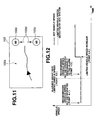
- Fig. 11 there is shown a form of informing or alarming the driver about the presence of the limited-vehicle-speed change in the forward traveling road.
- navigation information (map information) 100a and forward-traveling-road limited-vehicle-speed information 100b are displayed in an on-vehicle monitor 100.
- step S73 after the limited-vehicle-speed change has been alarmed through step S72, a check is made to determine, based on the driver's recommended-vehicle-speed SET switch operation information (an operational signal) from recommended-vehicle-speed SET switch 42, whether the driver has operated, responsively to the alarm, recommended-vehicle-speed SET switch 42.
- the answer to step S73 is affirmative (YES), that is, when recommended-vehicle-speed SET switch 42 has been operated by the driver responsively to the alarm, the routine proceeds to step S74.
- step S73 determines that the driver has operated recommended-vehicle-speed SET switch 42 responsively to the alarm.
- on-vehicle monitor 100 may be constructed by a touch-panel monitor configured to display a limited-vehicle-speed change.
- a driver's push onto a screen that displays a limited vehicle speed in the touch-panel monitor may be detected as a driver's recommended-vehicle-speed SET switch operation.
- step S74 a reservation for setting of set vehicle speed V SET to limited vehicle speed V LIMIT is made, and thereafter one execution cycle of the cruise vehicle speed setting processing of Fig. 10 terminates.
- step S71 when there is a limited-vehicle-speed change in the forward traveling road but the changed limited vehicle speed becomes less than the current set vehicle speed, or when there is no limited-vehicle-speed change in the forward traveling road, the routine proceeds from step S71 to step S63.
- step S63 of the ACC system of the second embodiment shown in Fig. 10 in a similar manner to step S63 of the first embodiment shown in Fig. 6 , a check is made to determine, based on the driver's recommended-vehicle-speed SET switch operation information (an operational signal) from recommended-vehicle-speed SET switch 42, whether recommended-vehicle-speed SET switch 42 is operated by the driver.
- recommended-vehicle-speed SET switch operation information an operational signal
- step S63 When recommended-vehicle-speed SET switch 42 is operated by the driver, the routine proceeds from step S63 to step S43. Conversely when recommended-vehicle-speed SET switch 42 is not operated by the driver, the routine proceeds from step S63 to step S75.
- step S75 a check is made to determine whether a specified condition, which enables or permits setting of set vehicle speed V SET for the ACC function to limited vehicle speed V LIMIT (the limited vehicle speed of the driving lane on which the host vehicle is currently traveling), detected by the system (in particular, navigation device 20), is satisfied or unsatisfied.
- a specified condition which enables or permits setting of set vehicle speed V SET for the ACC function to limited vehicle speed V LIMIT (the limited vehicle speed of the driving lane on which the host vehicle is currently traveling), detected by the system (in particular, navigation device 20), is satisfied or unsatisfied.
- V LIMIT the limited vehicle speed of the driving lane on which the host vehicle is currently traveling
- step S43 set vehicle speed V SET for the ACC function is set to the detected limited vehicle speed V LIMIT .
- the system of the second embodiment permits set vehicle speed V SET to be changed or set to a new limited vehicle speed (i.e., an increased limited vehicle speed), synchronously with a limited-vehicle-speed change (i.e., a limited-vehicle-speed increase).
- the system of the second embodiment determines that the driver does not wish a set-vehicle-speed change or the driver does not wish a set-vehicle-speed change synchronously with a limited-vehicle-speed change.
- the system of the second embodiment inhibits set vehicle speed V SET from automatically following the changed limited vehicle speed (the increased limited vehicle speed), with no driver's reservation for setting of set vehicle speed V SET to limited vehicle speed V LIMIT .
- the ACC system of the first embodiment enables or permits set vehicle speed V SET to be set or changed to limited vehicle speed V LIMIT (the limited vehicle speed of the driving lane on which the host vehicle is currently traveling) in accord with a driver's wishes in real time by virtue of a man-machine interface (recommended-vehicle-speed SET switch 42).
- V LIMIT the limited vehicle speed of the driving lane on which the host vehicle is currently traveling
- the ACC system of the second embodiment enables or permits set vehicle speed V SET to be set or changed to limited vehicle speed V LIMIT (the changed limited vehicle speed of the forward traveling road, on which the host vehicle will travel soon), in the presence of a reservation for setting of set vehicle speed V SET to limited vehicle speed V LIMIT , made by the driver in advance.
- the system of the second embodiment previously discussed in reference to the flowchart of Fig. 10 , is configured to permit the flow from step S71 through steps S72-S73 to step S74, only under a condition that a limited-vehicle-speed change in the forward traveling road occurs and additionally the changed limited vehicle speed becomes greater than the current set vehicle speed (the current limited vehicle speed of the driving lane on which the host vehicle is currently traveling).
- the system of the second embodiment may be somewhat modified as follows.
- the modified ACC system may be configured to permit the flow from step S71 through steps S72-S73 to step S74, under a condition that a limited-vehicle-speed change in the forward traveling road occurs and additionally the changed limited vehicle speed becomes less than the current set vehicle speed (the current limited vehicle speed of the driving lane on which the host vehicle is currently traveling) as well as under a condition that a limited-vehicle-speed change in the forward traveling road occurs and additionally the changed limited vehicle speed becomes greater than the current set vehicle speed (the current limited vehicle speed).
- the modified ACC system for instance, as clearly shown in Fig.
- the system of the second embodiment uses a presupposition that recommended-vehicle-speed SET switch 42 has already been operated by the driver and thus set vehicle speed V SET has already been set to limited vehicle speed V LIMIT (see the point 4-1 in Fig. 12 ). Without using such a presupposition that set vehicle speed V SET has already been set to limited vehicle speed V LIMIT , a reservation for setting of set vehicle speed V SET to limited vehicle speed V LIMIT may be executed.
- the ACC system may use at least a presupposition that the ACC function has already been activated (ON). Under such a presupposition (that is, in the ACC-function activated state), the system executes a reservation for setting (or changing) of set vehicle speed V SET to limited vehicle speed V LIMIT , when the driver has operated recommended-vehicle-speed SET switch 42 responsively to an alarm about a limited-vehicle-speed change in the forward traveling road (see the flow from step S71 through steps S72-S73 to step S74 in Fig. 10 ).
- set vehicle speed V SET is set to the previous set vehicle speed V SET(OLD) set with the ACC function activated previously, or to the host vehicle speed V at the point of time when a transition to the ACC-function activated state has occurred.
- the ACC system permits set vehicle speed V SET to be changed from the previous set vehicle speed V SET(OLD) or the host vehicle speed V to the changed limited vehicle speed (the next limited vehicle speed) (see the flow from step S75 to step S43 in Fig. 10 ).
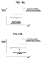
- the system configuration of the ACC system of the third embodiment is similar to that of the first embodiment, but the procedure executed within cruise vehicle speed setting section 40 of the ACC system of the third embodiment is somewhat different from the procedure (see the specified condition for setting of set vehicle speed V SET to limited vehicle speed V LIMIT at step S64) executed within cruise vehicle speed setting section 40 of the ACC system of the first embodiment, as hereunder described in detail in reference to the time charts of Figs. 13A-13B .
- the ACC system of the third embodiment is configured to determine, based on preceding vehicle information (e.g., the preceding vehicle acquisition flag, speed difference Vd between the host vehicle speed V and the preceding vehicle speed Vf, and vehicle-to-vehicle distance D between the preceding vehicle and the host vehicle) obtained by preceding vehicle information processing section 32, whether setting of set vehicle speed V SET to limited vehicle speed V LIMIT should be inhibited.
- preceding vehicle information e.g., the preceding vehicle acquisition flag, speed difference Vd between the host vehicle speed V and the preceding vehicle speed Vf, and vehicle-to-vehicle distance D between the preceding vehicle and the host vehicle
- the system inhibits (disables) setting of set vehicle speed V SET for the ACC function to limited vehicle speed V LIMIT even in the presence of the driver's recommended-vehicle-speed SET switch operation.
- set vehicle speed V SET is retained unchanged (i.e., kept at the set vehicle speed just before the driver's recommended-vehicle-speed SET switch operation).
- the ACC system of the third embodiment inhibits set vehicle speed V SET for the ACC function from automatically following the limited-vehicle-speed increase, thus temporarily disabling setting of set vehicle speed V SET to limited vehicle speed V LIMIT .
- set vehicle speed V SET is retained unchanged (i.e., kept at the limited vehicle speed just before the limited-vehicle-speed increase occurs).
- the ACC system of the third embodiment inhibits setting of set vehicle speed V SET to limited vehicle speed V LIMIT , which setting causes the ACC vehicle speed (host vehicle speed V) to increase. This avoids the host vehicle from undesirably approaching close to the preceding vehicle, thereby preventing the ill-timed setting of set vehicle speed V SET to limited vehicle speed V LIMIT in the ACC-function activated state from causing the driver to feel considerable discomfort.
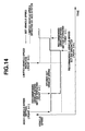
- the system configuration of the ACC system of the fourth embodiment is similar to that of the first embodiment, but the procedure (a method for setting or changing set vehicle speed V SET ) executed within cruise vehicle speed setting section 40 of the ACC system of the fourth embodiment is somewhat different from the procedure (see the method for setting or changing set vehicle speed V SET at step S64) executed within cruise vehicle speed setting section 40 of the ACC system of the first embodiment, as hereunder described in detail in reference to the time chart of Fig. 14 .
- the ACC system of the fourth embodiment is configured to store set vehicle speed V SET at the point of time when recommended-vehicle-speed SET switch 42 has been operated by the driver. That is, as a set vehicle speed value just before setting (or changing) set vehicle speed V SET to limited vehicle speed V LIMIT , the system stores the previous set vehicle speed V SET(OLD) set with the ACC function activated previously, or the host vehicle speed V at the point of time when a transition to the ACC-function activated state has occurred.
- the system of the fourth embodiment executes the setting or changing operation of set vehicle speed V SET , by reference to the stored set vehicle speed V SET(OLD) .
- the processing or method for setting set vehicle speed V SET for the ACC function to limited vehicle speed V LIMIT executed by the system of the fourth embodiment, fully taking into account the stored set vehicle speed, is hereunder explained in reference to the time chart of Fig. 14 .
Landscapes
- Engineering & Computer Science (AREA)
- Automation & Control Theory (AREA)
- Transportation (AREA)
- Mechanical Engineering (AREA)
- Human Computer Interaction (AREA)
- Control Of Driving Devices And Active Controlling Of Vehicle (AREA)
- Controls For Constant Speed Travelling (AREA)
- Traffic Control Systems (AREA)
Applications Claiming Priority (1)
| Application Number | Priority Date | Filing Date | Title |
|---|---|---|---|
| JP2007203232A JP5157304B2 (ja) | 2007-08-03 | 2007-08-03 | 車両用走行制御装置 |
Publications (2)
| Publication Number | Publication Date |
|---|---|
| EP2020331A1 true EP2020331A1 (de) | 2009-02-04 |
| EP2020331B1 EP2020331B1 (de) | 2016-12-21 |
Family
ID=39769188
Family Applications (1)
| Application Number | Title | Priority Date | Filing Date |
|---|---|---|---|
| EP08013195.6A Ceased EP2020331B1 (de) | 2007-08-03 | 2008-07-22 | Vorrichtung und Verfahren zur Führung eines Fahrzeugs |
Country Status (4)
| Country | Link |
|---|---|
| US (1) | US8103423B2 (de) |
| EP (1) | EP2020331B1 (de) |
| JP (1) | JP5157304B2 (de) |
| CN (1) | CN101357634B (de) |
Cited By (4)
| Publication number | Priority date | Publication date | Assignee | Title |
|---|---|---|---|---|
| WO2017008999A1 (de) * | 2015-07-14 | 2017-01-19 | Bayerische Motoren Werke Aktiengesellschaft | Längsführendes fahrerassistenzsystem in einem kraftfahrzeug |
| US10549754B2 (en) | 2015-07-14 | 2020-02-04 | Bayerische Motoren Werke Aktiengesellschaft | Longitudinally guiding driver assistance system in a motor vehicle |
| WO2020234371A1 (de) * | 2019-05-20 | 2020-11-26 | Audi Ag | Fahrerassistenzsystem für ein kraftfahrzeug und kraftfahrzeug |
| US11498557B2 (en) | 2015-07-14 | 2022-11-15 | Bayerische Motoren Werke Aktiengesellschaft | Longitudinally guiding driver assistance system in a motor vehicle |
Families Citing this family (30)
| Publication number | Priority date | Publication date | Assignee | Title |
|---|---|---|---|---|
| DE102005044174A1 (de) * | 2005-09-16 | 2007-03-22 | Bayerische Motoren Werke Ag | Abstandsbezogenes Fahrgeschwindigkeitsregelsystem |
| JP4862036B2 (ja) * | 2006-03-06 | 2012-01-25 | 日立オートモティブシステムズ株式会社 | 自動車の制御装置及び制御方法 |
| JP5157304B2 (ja) * | 2007-08-03 | 2013-03-06 | 日産自動車株式会社 | 車両用走行制御装置 |
| JP5322580B2 (ja) * | 2008-10-29 | 2013-10-23 | キヤノン株式会社 | ユーザーインターフェイス及びその制御方法、並びにプログラム、画像処理装置 |
| JP5168420B2 (ja) * | 2009-12-18 | 2013-03-21 | トヨタ自動車株式会社 | 走行制御装置 |
| US9234761B2 (en) * | 2011-05-06 | 2016-01-12 | Toyota Jidosha Kabushiki Kaisha | Vehicle course estimation device |
| SE536399C2 (sv) * | 2011-05-16 | 2013-10-08 | Scania Cv Ab | Förarinteraktion vid referenshastighetsreglerande farthållning |
| JP5915330B2 (ja) * | 2012-03-29 | 2016-05-11 | トヨタ自動車株式会社 | 走行制御装置 |
| WO2013186925A1 (ja) * | 2012-06-15 | 2013-12-19 | トヨタ自動車株式会社 | 追従制御装置 |
| US8831813B1 (en) | 2012-09-24 | 2014-09-09 | Google Inc. | Modifying speed of an autonomous vehicle based on traffic conditions |
| CN102927985A (zh) * | 2012-11-26 | 2013-02-13 | 昆山北极光电子科技有限公司 | 一种匀速运动物体的定点跟随方法 |
| US9609046B2 (en) * | 2014-04-29 | 2017-03-28 | Here Global B.V. | Lane level road views |
| JP5866498B2 (ja) * | 2014-05-07 | 2016-02-17 | パナソニックIpマネジメント株式会社 | 表示制御装置、投影装置、表示制御プログラム、および記録媒体 |
| JP6384794B2 (ja) * | 2014-05-07 | 2018-09-05 | パナソニックIpマネジメント株式会社 | 表示制御装置、表示制御方法、表示制御プログラム、および投影装置 |
| US9393963B2 (en) | 2014-09-19 | 2016-07-19 | Paccar Inc | Predictive cruise control system with advanced operator control and feedback |
| JP2016168985A (ja) * | 2015-03-16 | 2016-09-23 | トヨタ自動車株式会社 | 走行制御装置 |
| JP6319187B2 (ja) * | 2015-05-26 | 2018-05-09 | トヨタ自動車株式会社 | 車速制限システム |
| KR102285420B1 (ko) * | 2015-06-12 | 2021-08-04 | 주식회사 만도 | 차량의 순항 제어 시스템 및 그 제어 방법 |
| JP6319199B2 (ja) * | 2015-06-16 | 2018-05-09 | トヨタ自動車株式会社 | 車速制限システム |
| US10112610B2 (en) * | 2016-04-15 | 2018-10-30 | Robert Bosch Gmbh | Regional adjustment for driver assistance functions |
| KR102310545B1 (ko) * | 2016-06-10 | 2021-10-07 | 현대자동차주식회사 | 자동차의 속도 가변 제어 시스템 및 방법 |
| JP6519564B2 (ja) * | 2016-10-04 | 2019-05-29 | トヨタ自動車株式会社 | 車両走行制御装置 |
| CN106882186B (zh) * | 2017-03-22 | 2019-03-08 | 广州汽车集团股份有限公司 | 自适应巡航控制方法和系统 |
| JP7079070B2 (ja) | 2017-04-27 | 2022-06-01 | 株式会社ゼンリン | 走行支援装置及びプログラム |
| DE102017221740B4 (de) * | 2017-12-03 | 2024-06-06 | Audi Ag | Verfahren zum Betreiben eines Kraftfahrzeugs sowie entsprechendes Kraftfahrzeug |
| CN110555574B (zh) * | 2018-05-30 | 2022-11-01 | 宇通客车股份有限公司 | 一种无人驾驶车辆远程调度系统及控制方法 |
| JP2019061703A (ja) * | 2018-11-29 | 2019-04-18 | 株式会社ゼンリン | 走行支援装置、プログラム |
| CN110667377B (zh) * | 2019-10-16 | 2022-06-28 | 安徽安凯汽车股份有限公司 | 可调式最高车速限制系统 |
| DE102020204078A1 (de) * | 2019-11-27 | 2021-05-27 | Robert Bosch Gesellschaft mit beschränkter Haftung | Fahrerassistenzsystem für Kraftfahrzeuge |
| CN112559659B (zh) * | 2020-12-10 | 2021-12-24 | 首都师范大学 | 电子地图的生成方法及设备、行驶数据的采集方法及设备 |
Citations (5)
| Publication number | Priority date | Publication date | Assignee | Title |
|---|---|---|---|---|
| US6246948B1 (en) * | 1998-12-10 | 2001-06-12 | Ericsson Inc. | Wireless intelligent vehicle speed control or monitoring system and method |
| US20020022920A1 (en) * | 2000-08-17 | 2002-02-21 | Straub Michael P. | Method and apparatus for storing, accessing, generating and using information about speed limits and speed traps |
| US20020173881A1 (en) * | 2001-05-16 | 2002-11-21 | Lash David M.C. | Vehicle speed monitoring system and method |
| WO2002098695A1 (en) * | 2001-06-07 | 2002-12-12 | Harman/Becker Automotive Systems (Becker Division)Gmbh | Adaptive speed control system comprising a speed pilot for automobiles |
| JP2006321354A (ja) | 2005-05-19 | 2006-11-30 | Nissan Motor Co Ltd | 車両のクルーズ走行制御装置 |
Family Cites Families (6)
| Publication number | Priority date | Publication date | Assignee | Title |
|---|---|---|---|---|
| JPS61146644A (ja) * | 1984-12-19 | 1986-07-04 | Nissan Motor Co Ltd | 車両走行制御装置 |
| JP3642547B2 (ja) * | 1997-08-22 | 2005-04-27 | 株式会社小松製作所 | 自走車両の車速制御装置 |
| JP3608433B2 (ja) * | 1999-06-15 | 2005-01-12 | 日産自動車株式会社 | 先行車追従制御装置 |
| JP3620359B2 (ja) * | 1999-08-10 | 2005-02-16 | 日産自動車株式会社 | 車両用走行制御装置 |
| US7660658B2 (en) * | 2006-02-23 | 2010-02-09 | Qualcomm Incorporated | Apparatus and methods for speed management and control |
| JP5157304B2 (ja) * | 2007-08-03 | 2013-03-06 | 日産自動車株式会社 | 車両用走行制御装置 |
-
2007
- 2007-08-03 JP JP2007203232A patent/JP5157304B2/ja not_active Expired - Fee Related
-
2008
- 2008-07-22 EP EP08013195.6A patent/EP2020331B1/de not_active Ceased
- 2008-07-31 US US12/183,548 patent/US8103423B2/en active Active
- 2008-08-01 CN CN2008101354169A patent/CN101357634B/zh active Active
Patent Citations (5)
| Publication number | Priority date | Publication date | Assignee | Title |
|---|---|---|---|---|
| US6246948B1 (en) * | 1998-12-10 | 2001-06-12 | Ericsson Inc. | Wireless intelligent vehicle speed control or monitoring system and method |
| US20020022920A1 (en) * | 2000-08-17 | 2002-02-21 | Straub Michael P. | Method and apparatus for storing, accessing, generating and using information about speed limits and speed traps |
| US20020173881A1 (en) * | 2001-05-16 | 2002-11-21 | Lash David M.C. | Vehicle speed monitoring system and method |
| WO2002098695A1 (en) * | 2001-06-07 | 2002-12-12 | Harman/Becker Automotive Systems (Becker Division)Gmbh | Adaptive speed control system comprising a speed pilot for automobiles |
| JP2006321354A (ja) | 2005-05-19 | 2006-11-30 | Nissan Motor Co Ltd | 車両のクルーズ走行制御装置 |
Cited By (5)
| Publication number | Priority date | Publication date | Assignee | Title |
|---|---|---|---|---|
| WO2017008999A1 (de) * | 2015-07-14 | 2017-01-19 | Bayerische Motoren Werke Aktiengesellschaft | Längsführendes fahrerassistenzsystem in einem kraftfahrzeug |
| US10549754B2 (en) | 2015-07-14 | 2020-02-04 | Bayerische Motoren Werke Aktiengesellschaft | Longitudinally guiding driver assistance system in a motor vehicle |
| US10576979B2 (en) | 2015-07-14 | 2020-03-03 | Bayerische Motoren Werke Aktiengesellschaft | Longitudinal driver assistance system in a motor vehicle |
| US11498557B2 (en) | 2015-07-14 | 2022-11-15 | Bayerische Motoren Werke Aktiengesellschaft | Longitudinally guiding driver assistance system in a motor vehicle |
| WO2020234371A1 (de) * | 2019-05-20 | 2020-11-26 | Audi Ag | Fahrerassistenzsystem für ein kraftfahrzeug und kraftfahrzeug |
Also Published As
| Publication number | Publication date |
|---|---|
| JP2009035223A (ja) | 2009-02-19 |
| US20090037071A1 (en) | 2009-02-05 |
| US8103423B2 (en) | 2012-01-24 |
| EP2020331B1 (de) | 2016-12-21 |
| CN101357634B (zh) | 2012-04-18 |
| CN101357634A (zh) | 2009-02-04 |
| JP5157304B2 (ja) | 2013-03-06 |
Similar Documents
| Publication | Publication Date | Title |
|---|---|---|
| EP2020331B1 (de) | Vorrichtung und Verfahren zur Führung eines Fahrzeugs | |
| EP2022694B1 (de) | Vorrichtung und Verfahren zur Fahrzeuglaufsteuerung | |
| US20180345948A1 (en) | Longitudinal Driver Assistance System in a Motor Vehicle | |
| EP1065087B1 (de) | Fahrgeschwindigkeitsregelsystem zur optimierten Abstandsregelung | |
| JP5157531B2 (ja) | 車両用走行制御システム | |
| US8150583B2 (en) | Method and apparatus for avoiding or mitigating vehicle collisions | |
| CN109094560B (zh) | 一种自适应巡航方法及装置 | |
| JP3391013B2 (ja) | 自動車の前方道路状況対応制御装置 | |
| US20080243326A1 (en) | Information Output System for a Vehicle and Associated Information Output Method | |
| JPH08202991A (ja) | 自動車の前方道路状況対応制御装置 | |
| JP4774671B2 (ja) | 車両用情報提示装置 | |
| JP4715182B2 (ja) | 車両走行状況提示装置 | |
| JP3365117B2 (ja) | 自動車の前方道路状況対応制御装置 | |
| JP4239210B2 (ja) | 追従走行制御装置 | |
| JP3365118B2 (ja) | 自動車の前方道路状況対応制御装置 | |
| JP3365116B2 (ja) | 自動車の前方道路状況対応制御装置 | |
| JP2000118369A (ja) | 車両用走行制御装置 | |
| JPH08194888A (ja) | 自動車の前方道路状況対応制御装置 | |
| JP3365119B2 (ja) | 自動車の前方道路状況対応制御装置 | |
| JP2006290149A (ja) | 車両用走行制御装置 | |
| JP3365120B2 (ja) | 自動車の前方道路状況対応制御装置 | |
| JPH08194890A (ja) | 自動車の前方道路状況対応制御装置 | |
| JPH08202989A (ja) | 自動車の前方道路状況対応制御装置 | |
| JP3216461B2 (ja) | 自動車の前方道路状況対応制御装置 | |
| JPH08194889A (ja) | 自動車の前方道路状況対応制御装置 |
Legal Events
| Date | Code | Title | Description |
|---|---|---|---|
| PUAI | Public reference made under article 153(3) epc to a published international application that has entered the european phase |
Free format text: ORIGINAL CODE: 0009012 |
|
| 17P | Request for examination filed |
Effective date: 20080722 |
|
| AK | Designated contracting states |
Kind code of ref document: A1 Designated state(s): AT BE BG CH CY CZ DE DK EE ES FI FR GB GR HR HU IE IS IT LI LT LU LV MC MT NL NO PL PT RO SE SI SK TR |
|
| AX | Request for extension of the european patent |
Extension state: AL BA MK RS |
|
| AKX | Designation fees paid |
Designated state(s): DE FR GB |
|
| 17Q | First examination report despatched |
Effective date: 20100610 |
|
| GRAP | Despatch of communication of intention to grant a patent |
Free format text: ORIGINAL CODE: EPIDOSNIGR1 |
|
| INTG | Intention to grant announced |
Effective date: 20160801 |
|
| GRAS | Grant fee paid |
Free format text: ORIGINAL CODE: EPIDOSNIGR3 |
|
| GRAA | (expected) grant |
Free format text: ORIGINAL CODE: 0009210 |
|
| AK | Designated contracting states |
Kind code of ref document: B1 Designated state(s): DE FR GB |
|
| REG | Reference to a national code |
Ref country code: GB Ref legal event code: FG4D |
|
| REG | Reference to a national code |
Ref country code: DE Ref legal event code: R096 Ref document number: 602008047946 Country of ref document: DE |
|
| REG | Reference to a national code |
Ref country code: FR Ref legal event code: PLFP Year of fee payment: 10 |
|
| REG | Reference to a national code |
Ref country code: DE Ref legal event code: R097 Ref document number: 602008047946 Country of ref document: DE |
|
| PLBE | No opposition filed within time limit |
Free format text: ORIGINAL CODE: 0009261 |
|
| STAA | Information on the status of an ep patent application or granted ep patent |
Free format text: STATUS: NO OPPOSITION FILED WITHIN TIME LIMIT |
|
| 26N | No opposition filed |
Effective date: 20170922 |
|
| REG | Reference to a national code |
Ref country code: FR Ref legal event code: PLFP Year of fee payment: 11 |
|
| PGFP | Annual fee paid to national office [announced via postgrant information from national office to epo] |
Ref country code: GB Payment date: 20240620 Year of fee payment: 17 |
|
| PGFP | Annual fee paid to national office [announced via postgrant information from national office to epo] |
Ref country code: FR Payment date: 20240619 Year of fee payment: 17 |
|
| PGFP | Annual fee paid to national office [announced via postgrant information from national office to epo] |
Ref country code: DE Payment date: 20240619 Year of fee payment: 17 |
|
| REG | Reference to a national code |
Ref country code: DE Ref legal event code: R119 Ref document number: 602008047946 Country of ref document: DE |
|
| GBPC | Gb: european patent ceased through non-payment of renewal fee |
Effective date: 20250722 |
|
| PG25 | Lapsed in a contracting state [announced via postgrant information from national office to epo] |
Ref country code: GB Free format text: LAPSE BECAUSE OF NON-PAYMENT OF DUE FEES Effective date: 20250722 |
|
| PG25 | Lapsed in a contracting state [announced via postgrant information from national office to epo] |
Ref country code: DE Free format text: LAPSE BECAUSE OF NON-PAYMENT OF DUE FEES Effective date: 20260203 |
|
| PG25 | Lapsed in a contracting state [announced via postgrant information from national office to epo] |
Ref country code: FR Free format text: LAPSE BECAUSE OF NON-PAYMENT OF DUE FEES Effective date: 20250731 |