EP2015557A2 - Optischer Abtaster und Bilderzeugungsvorrichtung damit - Google Patents
Optischer Abtaster und Bilderzeugungsvorrichtung damit Download PDFInfo
- Publication number
- EP2015557A2 EP2015557A2 EP08252240A EP08252240A EP2015557A2 EP 2015557 A2 EP2015557 A2 EP 2015557A2 EP 08252240 A EP08252240 A EP 08252240A EP 08252240 A EP08252240 A EP 08252240A EP 2015557 A2 EP2015557 A2 EP 2015557A2
- Authority
- EP
- European Patent Office
- Prior art keywords
- reflection
- optical
- main scanning
- reflection mirror
- curvature
- Prior art date
- Legal status (The legal status is an assumption and is not a legal conclusion. Google has not performed a legal analysis and makes no representation as to the accuracy of the status listed.)
- Granted
Links
- 230000003287 optical effect Effects 0.000 title claims abstract description 228
- 238000012546 transfer Methods 0.000 claims description 40
- 238000011144 upstream manufacturing Methods 0.000 claims description 14
- 239000000969 carrier Substances 0.000 claims description 11
- 108091008695 photoreceptors Proteins 0.000 description 63
- 238000012937 correction Methods 0.000 description 22
- 238000000034 method Methods 0.000 description 13
- 230000008569 process Effects 0.000 description 11
- 239000011521 glass Substances 0.000 description 9
- 238000001514 detection method Methods 0.000 description 8
- 230000000052 comparative effect Effects 0.000 description 6
- 230000015572 biosynthetic process Effects 0.000 description 3
- 230000007423 decrease Effects 0.000 description 3
- 230000007246 mechanism Effects 0.000 description 2
- XAGFODPZIPBFFR-UHFFFAOYSA-N aluminium Chemical compound [Al] XAGFODPZIPBFFR-UHFFFAOYSA-N 0.000 description 1
- 229910052782 aluminium Inorganic materials 0.000 description 1
- 230000008859 change Effects 0.000 description 1
- 238000004140 cleaning Methods 0.000 description 1
- 238000010276 construction Methods 0.000 description 1
- 238000002474 experimental method Methods 0.000 description 1
- 239000000463 material Substances 0.000 description 1
- 238000012986 modification Methods 0.000 description 1
- 230000004048 modification Effects 0.000 description 1
- 238000012545 processing Methods 0.000 description 1
Images


Classifications
-
- H—ELECTRICITY
- H04—ELECTRIC COMMUNICATION TECHNIQUE
- H04N—PICTORIAL COMMUNICATION, e.g. TELEVISION
- H04N1/00—Scanning, transmission or reproduction of documents or the like, e.g. facsimile transmission; Details thereof
- H04N1/04—Scanning arrangements, i.e. arrangements for the displacement of active reading or reproducing elements relative to the original or reproducing medium, or vice versa
- H04N1/047—Detection, control or error compensation of scanning velocity or position
- H04N1/0473—Detection, control or error compensation of scanning velocity or position in subscanning direction, e.g. picture start or line-to-line synchronisation
-
- G—PHYSICS
- G02—OPTICS
- G02B—OPTICAL ELEMENTS, SYSTEMS OR APPARATUS
- G02B26/00—Optical devices or arrangements for the control of light using movable or deformable optical elements
- G02B26/08—Optical devices or arrangements for the control of light using movable or deformable optical elements for controlling the direction of light
- G02B26/10—Scanning systems
- G02B26/12—Scanning systems using multifaceted mirrors
- G02B26/125—Details of the optical system between the polygonal mirror and the image plane
- G02B26/126—Details of the optical system between the polygonal mirror and the image plane including curved mirrors
-
- G—PHYSICS
- G02—OPTICS
- G02B—OPTICAL ELEMENTS, SYSTEMS OR APPARATUS
- G02B27/00—Optical systems or apparatus not provided for by any of the groups G02B1/00 - G02B26/00, G02B30/00
- G02B27/0025—Optical systems or apparatus not provided for by any of the groups G02B1/00 - G02B26/00, G02B30/00 for optical correction, e.g. distorsion, aberration
- G02B27/0031—Optical systems or apparatus not provided for by any of the groups G02B1/00 - G02B26/00, G02B30/00 for optical correction, e.g. distorsion, aberration for scanning purposes
-
- G—PHYSICS
- G02—OPTICS
- G02B—OPTICAL ELEMENTS, SYSTEMS OR APPARATUS
- G02B27/00—Optical systems or apparatus not provided for by any of the groups G02B1/00 - G02B26/00, G02B30/00
- G02B27/0025—Optical systems or apparatus not provided for by any of the groups G02B1/00 - G02B26/00, G02B30/00 for optical correction, e.g. distorsion, aberration
- G02B27/0068—Optical systems or apparatus not provided for by any of the groups G02B1/00 - G02B26/00, G02B30/00 for optical correction, e.g. distorsion, aberration having means for controlling the degree of correction, e.g. using phase modulators, movable elements
-
- H—ELECTRICITY
- H04—ELECTRIC COMMUNICATION TECHNIQUE
- H04N—PICTORIAL COMMUNICATION, e.g. TELEVISION
- H04N1/00—Scanning, transmission or reproduction of documents or the like, e.g. facsimile transmission; Details thereof
- H04N1/04—Scanning arrangements, i.e. arrangements for the displacement of active reading or reproducing elements relative to the original or reproducing medium, or vice versa
- H04N1/113—Scanning arrangements, i.e. arrangements for the displacement of active reading or reproducing elements relative to the original or reproducing medium, or vice versa using oscillating or rotating mirrors
- H04N1/1135—Scanning arrangements, i.e. arrangements for the displacement of active reading or reproducing elements relative to the original or reproducing medium, or vice versa using oscillating or rotating mirrors for the main-scan only
-
- H—ELECTRICITY
- H04—ELECTRIC COMMUNICATION TECHNIQUE
- H04N—PICTORIAL COMMUNICATION, e.g. TELEVISION
- H04N1/00—Scanning, transmission or reproduction of documents or the like, e.g. facsimile transmission; Details thereof
- H04N1/04—Scanning arrangements, i.e. arrangements for the displacement of active reading or reproducing elements relative to the original or reproducing medium, or vice versa
- H04N1/12—Scanning arrangements, i.e. arrangements for the displacement of active reading or reproducing elements relative to the original or reproducing medium, or vice versa using the sheet-feed movement or the medium-advance or the drum-rotation movement as the slow scanning component, e.g. arrangements for the main-scanning
-
- H—ELECTRICITY
- H04—ELECTRIC COMMUNICATION TECHNIQUE
- H04N—PICTORIAL COMMUNICATION, e.g. TELEVISION
- H04N2201/00—Indexing scheme relating to scanning, transmission or reproduction of documents or the like, and to details thereof
- H04N2201/04—Scanning arrangements
- H04N2201/047—Detection, control or error compensation of scanning velocity or position
- H04N2201/04753—Control or error compensation of scanning position or velocity
- H04N2201/04758—Control or error compensation of scanning position or velocity by controlling the position of the scanned image area
- H04N2201/0476—Control or error compensation of scanning position or velocity by controlling the position of the scanned image area using an optical, electro-optical or acousto-optical element
- H04N2201/04762—Control or error compensation of scanning position or velocity by controlling the position of the scanned image area using an optical, electro-optical or acousto-optical element using a reflecting element
Definitions
- the present invention generally relates to an optical scanner and an image forming apparatus, such as a laser printer, a digital copier, a laser facsimile machine, etc., including the optical scanner.
- Tandem image forming apparatuses that form multicolor images are now widely used.
- Such tandem image forming apparatus includes multiple image carriers, such as photoreceptors, and an optical scanner that directs an optical scanning light (writing light) onto each image carrier so as to form an electrostatic latent image thereon.
- image carriers On the image carriers, different color images are formed, for example, by developing such electrostatic latent images with different color toners, and these images are transferred from the image carriers and superimposed one on another onto a transfer medium, such as a sheet of paper.
- a transfer medium such as a sheet of paper.
- the final multicolor image will have color deviation, which means that the superimposed single color images are not aligned with each other in the multicolor image.
- causes of such color deviation include curvature of a scanning line on the image carrier in a main scanning direction, which is hereinafter referred to as a main scanning line.
- the optical scanner is typically distorted slightly due to shape and assembly error of its components, such as optical parts and holders.
- a motor generates heat during optical scanning, which tends to thermally deform those optical scanner components.
- shape error, assembly error, and thermal deformation of the optical scanner components can cause curvature of the main scanning line.
- FIG. 1 illustrates a drum-shaped photoreceptor serving as an image carrier and main scanning lines directed on a surface thereof, an ideal main scanning line La and curved main scanning lines Lb and Lc.
- a center portion of the curved main scanning line Lb projects downstream in a sub-scanning direction, which is a direction in which the surface of the photoreceptor moves.
- a portion of the curved main scanning line Lc projects upstream in the sub-scanning direction.
- the direction in which the main scanning line curves is unique to each optical scanner because such curvature is caused by a combination of shape error, assembly error, and thermal deformation of the optical scanner components.
- the main scanning line on each of the multiple photoreceptors used in the tandem image forming apparatus curves in a direction unique to each image forming apparatus.
- an optical scanner to scan a plurality of objects respectively with optical beams emitted from an optical beam emitter includes a deflector assembly and a plurality of reflection optical systems.
- the deflector assembly includes at least one deflecting unit that deflects the optical beams in a main scanning direction.
- Each of the plurality of reflection optical systems includes a plurality of reflection mirrors to reflect one of the optical beams and a curvature adjustment unit.
- the curvature adjustment unit includes a holder structure to forcibly curve one of the reflection mirrors in a direction opposite the main scanning direction and a pressure unit to push the reflection mirror in a direction opposite the direction of the forcible curve.
- the curvature adjustment unit adjusts a direction and an amount of curvature of a main scanning line on the object to be scanned by adjusting an amount that the pressure unit deforms the reflection mirror.
- Each of the main scanning lines on the plurality of objects is curved in a similar direction due to the forcible curve of the reflection mirror formed by the holder structure.
- an optical scanner to scan a plurality of objects respectively with optical beams emitted from an optical beam emitter including a deflector assembly and a plurality of reflection optical systems.
- the deflector assembly includes at least one deflecting unit that respectively deflects the optical beams in a main scanning direction.
- Each of the plurality of reflection optical systems includes a plurality of reflection mirrors to reflect one of the optical beams, and an even number of curvature adjustment units.
- Each of the curvature adjustment units includes a holder structure to forcibly curve one of the plurality of reflection mirrors in a direction opposite the main scanning direction and a pressure unit to push the reflection mirror in a direction opposite the direction of the forcible curve.
- the curvature adjustment unit adjusts a direction and an amount of curvature of a main scanning line on the object by adjusting an amount that the pressure unit deforms the reflection mirror.
- a first half of the curvature adjustment units and a second half thereof curve the main scanning line in directions opposite to each other by respectively curving the reflection mirrors forcibly with the holder structures.
- an image forming apparatus includes a plurality of image carriers on each of which an electrostatic latent image is formed, the optical scanner described above, a plurality of developing units each configured to develop the electrostatic latent image formed on one of the image carriers, and a plurality of transferers each configured to transfer the developed image on one of the image carriers to a transfer member.
- the image forming apparatus 100 is a laser color printer in the present embodiment, and includes a housing 1 and a sheet cassette 2 that is removable from the housing 1 and contains sheets P (recording media).
- image forming stations 3Y, 3C, 3M, and 3K for forming yellow, cyan, magenta, and black toner images on drum-shaped photoreceptors 10Y, 10C, 10M, and 10K serving as image carriers, respectively, are provided.
- reference characters Y, M, C, and K show yellow, magenta, cyan, and black, respectively, and may be omitted in the description below when color discrimination is not necessary.
- Each of the photoreceptors 10Y, 10C, 10M, and 10K includes a cylindrical aluminum base having a diameter of about 40 mm and a photosensitive layer provided on a surface of the base.
- Examples of a material of the photosensitive layer include an organic photoconductor (OPC).
- a charger 11 to charge a surface of the photoreceptor 10
- a developing unit 12 to develop an electrostatic latent image formed thereon
- a cleaner 13 to clean the surface thereof are provided around the photoreceptor 10.
- an optical writing unit 4 serving as an optical scanner that optically scans the surfaces of the photoreceptors 10Y, 10C, 10M, and 10K with writing lights emitted from a laser diode serving as an optical beam emitter, not shown, is provided.
- an intermediate transfer unit 5 including an intermediate transfer belt 20 is provided above the image forming stations 3Y, 3C, 3M, and 3K.
- the intermediate transfer belt 20 serves as a transfer member onto which the toner images formed on the photoreceptors 10Y, 10C, 10M, and 10K are transferred.
- the image forming apparatus 100 further includes a fixer 6 to fix a toner image on the sheet P, located above the intermediate transfer unit 5, and toner bottles 7Y, 7C, 7M, and 7K containing yellow, cyan, magenta, and black toners, respectively, located in an upper portion of the housing 1.
- These toner bottles 7Y, 7C, 7M, and 7K can be removed and installed by opening a discharge tray 8 provided in the upper portion of the housing 1.
- the intermediate transfer belt 20 is looped around a driving roller 21, a tension roller 22, and a driven roller 23 and rotated counterclockwise in FIG. 2 .
- the intermediate transfer unit 5 further includes primary transfer rollers 24Y, 24C, 24M, and 24K, a secondary transfer roller 25, and a belt cleaner 26.
- the primary transfer rollers 24Y, 24C, 24M, and 24K transfer the toner images formed on the photoreceptors 10Y, 10C, 10M, and 10K, respectively, onto the intermediate transfer belt 20, and these images are superimposed one on another thereon.
- the secondary transfer roller 25 transfers the superimposed toner image from the intermediate transfer belt 20 onto the sheet P in a secondary transfer process.
- the belt cleaner 26 cleans the intermediate transfer belt 20.
- the image forming apparatus 100 further includes a feed roller 27 provided close to the sheet cassette 2, a pair of registration rollers 28, a pair of discharge rollers 29, and a controller to control respective portions thereof.
- FIG. 3 illustrates a schematic configuration of the image forming station 3Y. It is to be noted that the image forming stations 3C, 3M, and 3K has a configuration similar to that of the image forming station 3Y, and thus descriptions thereof omitted.
- the charger 11Y charges uniformly the surface of the photoreceptor 10Y, and then the optical writing unit 4 scans the surface of the photoreceptor 10Y with a writing light L according to image information, forming an electrostatic latent image thereon.
- the developing unit 20 develops the electrostatic latent image with yellow toner carried on a developing roller 15Y, shown in FIG. 3 , of the developing unit 12, thus forming a yellow toner image on the photoreceptor 10Y.
- the image forming stations 3C, 3M, and 3K form cyan, magenta, and black toner images on the photoreceptors 10C, 10M, and 10K, respectively.
- the primary transfer rollers 24Y, 24C, 24M, and 24K transfer the yellow, cyan, magenta, and black toner images from the photoreceptors 10Y, 10C, 10M, and 10K, respectively, and superimpose these images one on another on the intermediate transfer belt 20 that is rotating counterclockwise in FIG. 2 .
- Timing of image forming operations described above is different for each color so that the respective color toner images are superimposed one on another in an identical or similar portion of the intermediate transfer belt 20. More specifically, the image forming stations 3Y, 3C, 3M, and 3K start the image forming operations in order in a direction of movement of the intermediate transfer belt 20.
- each of the photoreceptors 10Y, 10C, 10M, and 10K is cleaned by a cleaning blade 13a, shown in FIG. 3 , of the cleaner 13 after the primary transfer process as preparation for subsequent image formation.
- the toners contained in the toner bottles 7Y, 7C, 7M, and 7K are supplied through transport paths, not shown, to the developing unit 12Y, 12C, 12M, and 12K in the image forming stations 3Y, 3C, 3M, and 3K, respectively, as required.
- the sheets P are fed one by one from the sheet cassette 2 by the feed roller 27 to the housing 1 and transported therethrough to the registration rollers 28.
- the registration rollers 28 forward the sheet P to a secondary transfer position, where the secondary transfer 25 transfers the toner image from the intermediate transfer belt 20 onto the sheet P.
- the discharge roller 29 discharges the sheet P onto the discharge tray 8.
- the belt cleaner 26 removes any toner remaining on the intermediate transfer belt 20.
- the image forming apparatus 100 may adopt a direct transfer method in which toner images formed on multiple photoreceptors are directly transferred onto a sheet transported by a transport belt.
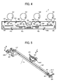
- the optical writing unit 4 is described below with reference to FIG. 4 .
- FIG. 4 illustrates the optical writing unit 4 together with the four photoreceptors 10Y, 10C, 10M, and 10K.
- the optical writing unit 4 includes polygon mirrors 41a and 41b shaped like regular-polygon columns, first reflection mirrors 44Y, 44C, 44M, and 44K, second reflection mirrors 45Y, 45C, 45M, and 45K, and third reflection mirrors 46Y, 46C, 46M, and 46K.
- the optical writing unit 4 further includes a laser diode as the optical beam emitter to beam writing lights (laser lights) Ly, Lc, Lm, and Lk.
- a laser diode as the optical beam emitter to beam writing lights (laser lights) Ly, Lc, Lm, and Lk.
- Each of the polygon mirrors 41a and 41b in the present embodiment has six faces, each of which is provided with a reflection mirror, and these polygon mirrors 41a and 41b are vertically connected together concentrically, with centers of the regular-polygon columns aligned with each other.
- the polygon mirrors 41a and 41b are rotated at high speed on an identical rotation axis by a polygon motor, not shown.
- their mirror faces deflect the writing lights Ly, Lc, Lm, and Lk in the main scanning direction so as to scan the surface of the photoreceptors 10Y, 10C, 10M, and 10K, respectively.
- the polygon mirror 41a deflects the writing lights Lc and Lm that are directed thereto from opposite directions
- the polygon mirror 41b deflects the writing lights Ly and Lk that are directed thereto from opposite directions.
- the polygon mirrors 41a and 41b and a polygon motor, not shown, serve as a deflector assembly to deflect the writing lights Ly, Lc, Lm, and Lk, and the polygon mirrors 41a and 41b serve as a deflecting unit.
- the optical writing unit 4 further includes four reflection optical systems for yellow, cyan, magenta, and black, soundproof glasses 42a and 42b, scan lenses 43a and 43b, and dustproof glasses 48Y, 48C, 48M, and 48K.
- the polygon motor, not shown, and the polygon mirrors 41a and 41b are covered with a polygon cover to muffle the sound thereof.
- the polygon cover is provided with the soundproof glasses 42a and 42b, and the writing lights Ly, Lc, Lm, and Lk (optical beams) pass through the polygon cover through one of the soundproof glasses 42a and 42b.
- writing lights Ly and Lc pass through the soundproof glass 42a, and the writing lights Lm and Lk pass through the soundproof glass 42b.
- the writing lights Ly and Lc After passing though the soundproof glass 42a while being deflected by one of the polygon mirrors 41a and 41b, the writing lights Ly and Lc further penetrate the scan lens 43a in vertical alignment.
- the scan lens 43a changes uniform angular movement of the polygon mirrors 41a and 41b into uniform linear movement by concentrating the writing lights Ly and Lc in both the main scanning direction and sub scanning direction.
- the scan lens 43a corrects optical face tangle error of the polygon mirrors 41a and 41b.
- Optical face tangle error means that a reflection face of the polygon mirrors is relatively oblique in a sub-scanning direction due to error in construction and makes scanning pitch uneven.
- the writing lights Lm and Lk pass through the polygon cover through the soundproof glass 42b and further pass through the scan lens 43b located opposite the scan lens 43a with respect to the polygon cover.
- Each of the four reflection optical systems of the optical writing unit 4 includes one laser diode, not shown, the first reflection mirror 44, the second reflection mirror 45, and the third reflection mirror 46. More specifically, for example, the yellow reflection optical system includes the laser diode for yellow, the first reflection mirror 44Y, the second reflection mirror 45Y, and the third reflection mirror 46Y. Each of the first reflection mirror 44Y, the second reflection mirror 45Y, and the third reflection mirror 46Y are mirrors without lens mechanisms.
- the writing lights Ly, Lc, Lm, and Lk After passing through one of the scan lens 43a and 43b, the writing lights Ly, Lc, Lm, and Lk are directed to the first reflection mirror 44, the second reflection mirror 45, and the third reflection mirror 46 in the reflection optical systems, respectively.
- the writing light Ly changes directions three times by being reflected by the first reflection mirror 44Y, the second reflection mirror 45Y, and the third reflection mirror 46Y sequentially, and then reaches the surface of the photoreceptor 10Y.
- the writing lights Lc, Lm, and Lk are directed to the surface of the photoreceptors 10C, 10M, and 10K, respectively.
- the writing lights Ly, Lc, Lm, and Lk pass through the dustproof glasses 48Y, 48C, 48M, and 48K provided on an upper surface of the optical writing unit 4 and then reach the surface of the photoreceptors 10Y, 10C, 10M, and 10K, respectively.
- Each reflection optical system of the optical writing unit 4 is provided with a curvature adjustment unit and an inclination adjuster.
- the curvature adjustment unit includes a holder structure and a pressure unit and adjusts a direction and an amount of curvature of a main scanning line, which is a line of a writing light scanning the surface of the photoreceptor 10 in the main scanning direction, by adjusting curvature of one of the reflection mirrors 44, 45, and 46.
- the inclination adjuster adjusts inclination of the reflection mirrors 44, 45, and 46.
- FIG. 5 is a perspective view illustrating a configuration around the third reflection mirror 46Y, as viewed from a back side that is opposite a mirror side onto which the writing light Ly is directed.
- the third reflection mirror 46Y is held by a holder 52Y with both end portions thereof in a longitudinal direction projecting from the holder 52Y.
- One of the end portions of the reflection mirror 46Y contacts an inclination adjustment unit 560Y serving as the inclination adjuster that includes a pulse motor 56Y and a motor holder 57Y.
- the end portion of the reflection mirror 46Y on the side where the inclination adjustment unit 560Y is located is swingable in a direction indicated by arrow C.
- the side where the inclination adjustment unit 560Y is located is hereinafter referred to as an adjuster side.
- projections 52aY protruding toward the third reflection mirror 46Y are provided on both end portions of the holder 52Y, respectively.
- Fixing members 54Y respectively located at both end portions of the reflection mirror 46Y bind together the third reflection mirror 46Y the holder 52Y, and positions of the fixing members are closer to a center portion of the third reflection mirror 46Y in the longitudinal direction than positions of the projections 52aY.
- the center portion of the third reflection mirror 46Y in the longitudinal direction is simply referred to as a center portion of the third reflection mirror 46Y unless otherwise specified.
- the holder 52Y and the fixing members 54Y serve as the holder structure.
- the side of the third reflection mirror 46Y in the longitudinal direction opposite the adjuster side is hereinafter referred to as a support side.
- the end portion of the third reflection mirror 46Y on the support side is mounted on a mount 66Y that is fixed to the housing 1 of the image forming apparatus 100 shown in FIG. 2 .
- This end portion on the support side is sandwiched between the mount 66Y and a plate spring 69 that presses against the back side thereof and is fixed to the housing 1 of the image forming apparatus 100 shown in FIG. 2 .
- a pressure unit 650Y including a curvature adjustment pulse motor 65Y and a motor holder 67 is attached to a back surface of the holder 52Y opposite its surface facing the third reflection mirror 46Y. This pressure unit 650Y pushes the center portion of the third reflection mirror 46Y in a direction indicated by arrow B.
- FIG. 6 is a lateral side view illustrating the inclination adjustment unit 560Y, as viewed from a side, and FIG. 7 is a plan view thereof.
- the inclination adjustment unit 560Y further includes an adjuster 58Y.
- the pulse motor 56Y includes a rotary shaft 56aY on which a male screw 56bY is provided.
- the male screw 56bY of the pulse motor 56Y engages a female screw 58a provided inside the adjuster 58Y, attaching the adjuster 58Y to the rotary shaft 56aY.
- the adjuster 58Y has a D-shaped cross-section and is inserted into a D-shaped engagement portion 57aY provided on the motor holder 57.
- the adjuster 58Y engages the engagement portion 57aY and does not rotate even when the rotary shaft 56aY of the pulse motor 56Y rotates.
- the adjuster 58Y moves vertically, as indicated by arrow D in FIG. 6 , due to engagement of the male screw 56bY and the female screw 58a.
- the motor holder 57Y holding the pulse motor 56Y is fixed to the housing 1 of the image forming apparatus 100 shown in FIG. 2 , and an end portion of the adjuster 58Y engaging the male screw 56bY of the pulse motor 56Y contacts a mirror surface of the end portion of the third reflection mirror 46Y, although not shown in FIG. 5 .
- a distance (amount) that the adjuster 58Y pushes the end portion of the third reflection mirror 46Y on the adjuster side to move changes.
- the adjuster side end portion of the third mirror 46Y swings on its support side end portion that is sandwiched between the mount 66Y and the plate spring 69 in a direction, indicated by arrow C, in which the adjuster 58Y moves.
- the inclination of the third reflection mirror 46Y changes.
- the inclination of the third reflection mirror 46Y is adjusted by changing an amount of rotation of the pulse motor 56Y.
- a cam can be used as the adjuster 58Y.
- FIG. 8 is a plan view illustrating a configuration around the third reflection mirror 46Y, as viewed from a direction perpendicular to a direction in which the writing light Ly travels.
- the pressure unit 650Y including the curvature adjustment pulse motor 65Y and the motor holder 67Y is attached to the back surface of the holder 52Y, as described above.
- the pressure unit 650 further includes a curvature adjuster 68Y engaging a rotary shaft of the curvature adjustment pulse motor 65Y, and an apex of the curvature adjuster 68Y contacts the back surface of the center portion of the holder 52Y in the longitudinal direction.
- a female screw is provided inside the curvature adjuster 68Y and engages a male screw provided on the rotary shaft of the curvature adjustment pulse motor 65Y.
- the curvature adjustment unit includes the pressure unit 650Y, the holder 52Y, and the fixing members 54Y.
- the curvature adjuster 68Y moves vertically according to screw mechanism similar to that of the inclination adjustment unit 560Y shown in FIG. 6 to push to move a center portion of the third reflection mirror 46Y in a direction opposite the direction of the forcible curve caused by the holder structure. That is, the curvature adjustment pulse motor 65Y changes the distance (amount) that the curvature adjuster 68Y push to move the center portion of the third reflection mirror 46Y in a direction opposite the direction of the forcible curve.
- an amount that the pressure unit 650 deforms the third reflection mirror 46Y is changed by changing an amount of rotation of the curvature adjustment pulse motor 65Y, and the curvature of the main scanning line is adjusted by changing the deformation amount of the third reflection mirror 46Y.
- a cam can be used as the curvature adjuster 68Y.
- FIG. 9 is a perspective view illustrating the third reflection mirror 46Y and the holder 52Y as viewed from the mirror side
- FIG. 10 is an end-on side view thereof as viewed from a side of the end portion that is a direction indicated by arrow C1 shown in FIG. 9 .
- the fixing members 54Y binding the third reflection mirror 46Y and the holder 52Y together at both end portions thereof are C-shaped.
- each fixing member 54Y engages, like a hook, edge portion of the third reflection mirror 46Y in a direction indicated by arrow C2, thus pushing the third reflection mirror 46Y to the holder 52Y.
- each fixing member 54Y push the third reflection plate 46Y at the portion closer to the center portion than the positions of the projections 52aY as described above, thus curving the third reflection mirror 46Y in a direction indicated by a curve line R so that its center portion project toward the side of the holder 52Y.
- the holder 52Y and the fixing members 54Y forcibly hold the third reflection mirror 46Y in a curved state.
- the forcibly curved state of the third reflection mirror 46Y is not recognizable in FIG. 8 , its direction is toward the pressure unit 650 as indicated by a curve line R shown in FIG. 9 .
- the curvature adjuster 68Y pushes the center portion of the third reflection mirror 46Y in a direction opposite the forcible curve thereof formed by the holder 52Y and the fixing members 54Y, thus straightening the third reflection mirror 46Y or curving the reflection mirror 46Y to the opposite direction.
- the third reflection mirror 46Y can be curved in both the mirror side and the back side as described above, curvature of the main scanning line on the photoreceptor 10 in the sub scanning direction can be corrected even when the main scanning line projects either upstream or downstream in the sub scanning direction.
- the cyan, magenta, and black reflection optical systems are configured similarly to the yellow reflection optical system, although the description above concerns the inclination adjustment unit 560 and the curvature adjustment unit including the holder 52, the fixing members 54, and the pressure unit 650 of the yellow reflection optical system.
- the inclination adjustment unit 560 and the curvature adjustment unit are attached to the third reflection mirror 46 in yellow and cyan reflection optical systems, these are attached to the second reflection mirror 45 in the magenta and black reflection optical systems.
- Curvature of the reflection mirror and the curvature of the main scanning line on the photoreceptor 10 are described in detail below with reference to FIGs. 11 through 18 .
- FIGs. 11 illustrates a configuration around a reflection mirror 51 of a comparative optical writing unit.
- the reflection mirror 51 is one of multiple reflection mirrors to direct a writing light (optical beam) onto one of multiple photoreceptors, not shown, reflecting the writing light several times.
- the reflection mirror 51 is held by a holder 52Z provided on its back side that is a non-mirror side.
- This holder 52Z holds the reflection mirror 51 in a forcibly curved state in which a center portion thereof in a longitudinal direction projects from a mirror side to the back side that is a direction indicated by arrow B1.
- a pressure unit 64 is provided on a back side of ) the holder 52Z opposite a side of the reflection mirror 51 and pushes the center portion of the reflection mirror 51 via the holder 52Z to the mirror side that is a direction indicated by arrow B2.
- the reflection mirror 51 When the pressure unit 64 shown in FIG. 11 pushes the reflection mirror 51 further, the reflection mirror 15 curves in a direction opposite the forcible curvature formed by the holder 52Z as shown in FIG. 14 .
- the reflection mirror 51 can be curved in both the mirror side and the back side.
- the main scanning lines on the photoreceptors are typically adjusted before shipment and at predetermined or preferable intervals during operation.
- the main scanning lines on the respective photoreceptors are adjusted each time a predetermined or preferable number of sheets are printed or at timing designated by the user during operation.
- electrostatic latent images for detecting positional deviation are formed on the photoreceptors 10Y, 10C, 10M, and 10K shown in FIG. 4 , and developed with respective color toners into detection toner images, respectively, through processes similar to the normal image forming processes described above.
- These detection toner images are transferred onto different positions of the intermediate transfer belt 20 shown in FIG. 3 , and thus the respective color detection toner images are aligned in a predetermined or preferable pattern.
- an optical sensor not shown, detects these detection toner images.
- the controller determines deviation in relative positions among the detection toner images according to a timing with which the optical sensor, not shown, detects the detection toner images and then calculates an amount of inclination of the yellow, cyan, and magenta main scanning lines, respectively, with respect to the black main scanning line based on results of the detection so as to minimize the positional deviation.
- the controller rotates the pulse motor 56Y of the inclination adjustment unit 560Y shown in FIG. 5 in either a positive direction or a reverse direction for a predetermined or preferable rotation angle.
- the controller rotates the pulse motor 56Y of the inclination adjustment unit 560Y shown in FIG. 5 in either a positive direction or a reverse direction for a predetermined or preferable rotation angle.
- FIG. 15 illustrates main scanning lines L1, indicated by dotted lines, that are not adjusted and an adjusted main scanning line L2 indicated by a solid line.
- the inclination of the main scanning lines L1 can be adjusted to the main scanning line L2 through the processes described above.
- Adjustment of curvature of the main scanning line is described below with reference to FIG. 16 .
- the curvature of the main scanning lines on the respective photoreceptors 10 is adjusted at a timing similar to that of the inclination adjustment.
- the reflection mirror is curved in the direction indicated by the curve line R shown in FIG. 9 .
- the main scanning line curves like an initial main scanning line L3 indicated by a dotted line shown in FIG. 16 .
- a reference character L4 indicates an adjusted main scanning line indicated by a solid line.
- the curvature of the initial main scanning line L3 shown in FIG. 16 can be corrected by rotating, in the case of yellow, the curvature adjustment pulse motor 65Y shown in FIG. 8 in such initial state so as to move the curvature adjuster 68Y to contact the back surface of the center portion of the third reflection mirror 46Y and then adjusting an amount of elevation of the curvature adjuster 68Y pushing against the third reflection mirror 46Y.
- the controller includes a CPU (central processing unit) and determines an amount of curvature of the main scanning line for each color based on the results of the detection of the toner images for positional deviation and then calculates an amount of inclination of the reflection mirror for each color so as to minimize the curvature of the main scanning lines.
- CPU central processing unit
- the controller rotates the curvature adjustment pulse motor 65Y shown in FIG. 8 in either a positive direction or a reverse direction for a predetermined or preferable rotation angle so as to change the amount of deformation of the third reflection mirror caused by the pressure unit 650.
- the direction and the amount of the curvature of the third reflection mirror 46Y are changed, which can correct the main scanning line.
- the cyan, magenta, and black main scanning lines are similarly adjusted.
- an actual main scanning line after adjustment might be W-shaped as shown in FIG. 17 or M-shaped as shown in FIG. 18 . Therefore, differences in the shape of the main scanning line after adjustment is described below.
- FIG. 17 illustrates a corrected main scanning line on one of the multiple photoreceptors
- FIG. 18 illustrates a corrected main scanning line on another photoreceptor.
- a dotted line indicates an ideal main scanning line that is straight
- a solid line indicate an actual corrected main scanning line.
- the actual corrected main scanning lines shown in FIGs. 17 and 18 wave slightly within widths ⁇ t1 and ⁇ t2, respectively. As is clear when these corrected main scanning lines are compared, the shapes of the corrected main scanning lines on different photoreceptors are different from each other.
- the corrected main scanning line shown in FIG. 17 is W-shaped having a center apex projecting downstream and both end portions projecting upstream in a direction indicated by arrow B3.
- the corrected main scanning line shown in FIG. 18 is M-shaped having center apex projecting upstream and both end portions projecting downstream in the direction indicated by arrow B3.
- the main scanning lines on respective photoreceptors preferably have an identical or similar shape.
- the curvature of the center portion of the main scanning line projects in opposite directions because an initial curvature of the reflection mirror 51 shown in FIG. 11 projects in opposite directions between FIGs. 17 and 18 .
- the initial curvature of the reflection mirror 51 is caused by the holder 52Z while the pressure unit 64 does not push the reflection mirror 51.
- the direction of the initial curvature of the reflection mirror is different when the reflection mirrors provided in the multiple photoreceptors face opposite directions although being forcibly curved in a similar direction (from the mirror side to the back side) by the holder.
- the main scanning line projects in different directions when the optical beam is reflected in a different number of times after being reflected by the reflection mirror provided with the curvature adjustment unit, that is, when the number of the reflection mirrors provided downstream of that reflection mirror in an optical beam path is different, even when the reflection mirrors provided in the multiple photoreceptors face a similar direction.
- the main scanning line is reversed and accordingly its shape changes between W-shape and M-shape each time it is reflected downstream of that reflection mirror being curved by the holder, which is hereinafter referred to as a curvature correction mirror.
- the third reflection mirror 46 is provided the furthest downstream of all the multiple reflection mirrors in the optical beam path.
- the third reflection mirrors 46Y and 46C and the third reflection mirrors 46M and 46K face in opposite directions because their relative position with the polygon mirrors 41a and 41b is different from each other.
- the sub scanning direction which is the direction in which the photoreceptor 10Y rotates, is from the right to the left in FIG. 4 at a contact point between the photoreceptor 10 and the writing light L.
- the yellow reflection optical system is located downstream of the polygon mirrors 41a and 41b in the sub scanning direction described above.
- the cyan reflection optical system is located downstream of the polygon mirrors 41a and 41b in the sub scanning direction.
- the magenta and black reflection optical systems are located upstream of the polygon mirrors 41a and 41b in the sub scanning directions.
- the reflection mirrors having identical alignment order in the direction in which the writing light travels in the respective reflection optical systems face in opposite directions. That is, the second reflection mirrors 46Y and 46C and the second reflection mirrors 46M, and 46K face in opposite directions, and the third reflection mirrors 46Y and 46C and the third reflection mirrors 46M and 46K face in opposite directions.
- the relative position of the yellow and cyan reflection optical systems with the polygon mirrors 41a and 41b in the sub scanning direction is opposite that of the magenta and black reflection optical systems because the polygon mirrors 41a and 41b are located between the yellow and cyan reflection optical systems and the magenta and black reflection optical systems as shown in FIG. 4 .
- the layout described above is intended to make the optical writing unit 4 compact and enhance the accuracy of scanning positions. More specifically, if all the reflection optical systems are located either downstream or upstream of the polygon mirrors 41a and 41b in the sub scanning direction in the optical writing unit 4, the polygon mirrors 41a and 41b must be located on the right or left of all the reflection optical systems in FIG. 4 . Such a layout will expand the optical writing unit 4 horizontally.
- the optical beam path between the polygon mirrors 41a and 441b and the black reflection optical system becomes longer, which will decrease accuracy of the black scanning position. If the polygon mirrors 41a and 41b are located on the right of the black reflection optical system in FIG. 4 , accuracy of the yellow scanning position will decrease similarly.
- the polygon mirrors 41a and 41b are located between the yellow and cyan reflection optical systems and the magenta and black reflection optical systems in the present embodiment.
- the inclination adjustment unit and the curvature adjustment unit are provided on the second reflection mirrors 45M and 45K in the magenta and black reflection optical systems, respectively, as described above.
- the magenta and black main scanning lines which are M-shaped on the second reflection mirrors 45M and 45K, are reflected to be W-shaped on the third reflection mirrors 46M and 46K and then directed to the photoreceptor 10M and 10K, respectively.
- the main scanning line is W-shaped on all the photoreceptors 10Y, 10C, 10M, and 10K, and accordingly the color deviation in the superimposed toner image can be further reduced.
- the inclination adjustment unit and the curvature adjustment unit are provided on the second reflection mirrors 45Y and 45C in the yellow and cyan reflection optical systems and on the third reflection mirrors 46M and 46K in the magenta and black reflection optical systems.
- all the main scanning lines of the respective photoreceptors 10 are M-shaped.
- the curvature adjustment unit is provided on the reflection mirror whose alignment order in the direction in which the optical beam (writing light) travels is odd.
- the direction in which the optical beam travels is herein after referred to as the direction of optical beam.
- the curvature adjustment unit is provided on the reflection mirror whose alignment order in the direction of optical beam is even.
- the main scanning lines on the respective photoreceptors 10 can have a similar shape.
- the optical writing unit 4 includes the optical beam emitters, the multiple reflection optical systems, and the deflector assembly including the polygon mirrors 41a and 41b.
- the reflection optical systems direct the different'writing lights emitted by the optical beam emitters to different objects to be scanned, respectively.
- Each reflection optical system includes the first reflection mirror 44, the second reflection mirror 45, and the third reflection mirror 46, and an inclination adjustment unit to adjust inclination of at least one of the reflection mirrors.
- Each reflection optical system further includes the curvature adjustment unit including the holder structure, the pressure unit, and the curvature adjuster.
- the holder structure includes the holder 52 and the fixing members 54, and forcibly curves at least one of those reflection mirrors that is the curvature correction mirror in the direction opposite the main scanning direction.
- the pressure unit 650 includes the curvature adjustment pulse motor 65 to push the curvature correction mirror in the direction opposite the direction of the initial curvature and adjusts the direction and the amount of the curve of the main scanning direction on the photoreceptor 10 by changing the amount (distance) the pressure unit 650 moves the center portion of the curvature correction mirror in the direction opposite the direction of the initial curvature (forcible curve), that is, the amount that the pressure unit 650 deforms the curvature correction mirror.
- the direction of the initial curvature of the main scanning line caused by the holder structure is similar on all of the objects to be scanned (photoreceptors 10). Because the pressure unit 650 pushes the curvature correction mirror in this state, the main scanning lines on the all the objects to be scanned have a similar shape, and thus color deviation of a multicolor image can be reduced.
- the initial curvature of the main scanning line can be in a similar direction on the different objects by setting their directions individually in the reflection optical systems, and then setting their directions to a similar direction.
- each of the reflection optical systems includes multiple reflection mirrors, even if the main scanning lines in the reflective optical systems curve in different directions from each other immediately after being reflected by the curvature correction mirror, the direction of the initial curvature of the main scanning line can be similar in respective reflection optical systems as follows: While the main scanning lines curving in one direction are reflected an even number of times, the other main scanning lines are reflected an odd number of times. Alternatively, the main scanning lines curving in one direction may be reflected zero times and the other main scanning lines may be reflected once.
- magenta and black reflection optical systems are located downstream of the deflecting unit in the sub scanning direction while the yellow and cyan reflection optical systems are located upstream of the deflecting unit in the sub scanning direction.
- the optical writing unit 4 can be compact and accuracy of scanning positions can be enhanced.
- each reflection optical system includes an identical number of reflection mirrors, that is, three reflection mirrors. While the curvature adjustment unit is provided on the third reflection mirror 46 whose alignment order among those three reflection mirrors is first, an odd number, in a direction opposite the direction of optical beam in the yellow and cyan reflection optical systems, the curvature adjustment unit is provided on the second reflection mirror 45 whose alignment order is second, an even number, in the magenta and black reflection optical systems.
- the main scanning lines on all the photoreceptors can have a similar shape even when at least one of the reflection optical system is located upstream of the deflecting unit and the rest of those are located downstream thereof for compactness of the optical writing unit and/or higher accuracy of scanning positions.
- FIG. 19 illustrates an optical writing unit 4A according to a variation of the present embodiment, together with the photoreceptors 10Y, 10C, 10M, and 10K.
- the optical writing unit 4A includes four reflective optical systems for yellow, cyan, magenta, and black, a deflector assembly, and scan lenses 43a and 43b.
- the deflector assembly includes two deflecting units.
- the optical writing unit 4A includes two reflection-deflection optical systems YC and MK.
- the reflection-deflection optical system YC includes the reflection optical systems for yellow and cyan and polygon mirrors 41a and 41b serving as one deflecting unit
- the reflection-deflection optical system MK includes the reflection optical systems for magenta and black and polygon mirrors 41c and 41d serving as another deflecting unit.
- the yellow and cyan reflection optical systems are located downstream of the polygon mirrors 41a and 41b in a sub scanning direction in FIG. 19 .
- the magenta and black reflection optical systems are located downstream of the polygon mirrors 41c and 41d in the sub scanning direction in FIG. 19 .
- Each of the reflection optical systems includes a first reflection mirror 44, a second reflection mirror 45, and a third reflection mirror 46 and directs a writing light L emitted by an optical beam emitter, not shown, onto the photoreceptor 10 similarly to those of the optical writing unit 4 shown in FIG. 4 .
- the reflection mirror whose alignment order in the direction of optical beam is identical faces in a similar or identical direction in all of the multiple reflection optical systems.
- the main scanning lines on the photoreceptors 10Y, 10C, 10M, and 10K have a similar shape.
- the deflector assembly includes the multiple deflecting units, and the multiple reflection optical systems are divided into two reflection-deflection groups, the reflection-deflection optical systems YC and MK, each provided with one of the deflecting units.
- the reflection-deflection optical systems YC and MK the relative position of the deflecting unit and each reflection optical system in a sub scanning direction are similar.
- the main scanning lines on all photoreceptors can have a similar shape.
- optical writing unit according to another variation of the present embodiment is described below. It is to be noted that, unless otherwise specified, the optical writing unit described below has a configuration similar to that of the optical writing unit 4 shown in FIG. 4 .
- each curvature adjustment unit is provided in each of the reflection optical systems for yellow, cyan, magenta, and black.
- one of these curvature adjustment units is attached to the second reflection mirror 45
- the other curvature adjustment unit is attached to the third reflection mirror 46.
- the second reflection mirrors 45Y and 45C and the third reflection mirrors 46Y and 46C face opposite each other in the yellow and cyan reflection optical systems.
- the second reflection mirrors 45M and 45K and the third reflection mirrors 46M and 46K face opposite to each other in the magenta and black reflection optical systems.
- the alignment order of one curvature correction mirror (third reflection mirror 46) among the multiple reflection mirrors is an odd number and that of the other curvature correction mirror (second reflection mirror 45) is an even number.
- convexity of the W-shape can be offset by concavity of the M-shape in the main scanning line, and thus the main scanning line can be better straightened.
- the optical writing unit can reduce distortion of images as well as the color deviation in multicolor images.
- each reflection optical system includes two curvature correction mirrors that face directions opposite each other in order to better straighten the main scanning line by offsetting the convexity of the W-shape with the concavity of the M-shape.
- the number of the curvature correction mirrors is not limited to two and can be any even number.
- a first half of the curvature correction mirrors forcibly curve the main scanning line on the object with the holder structure in one direction
- a second half of the curvature correction mirrors curve the main scanning line on the object with the holder structure in the direction opposite the direction of the first half of the curvature correction mirrors.
- the alignment order of the third reflection mirror 46 which is the first half of the curvature correction mirrors
- the alignment order of the second reflection mirror 45 which is the second half of the curvature correction mirrors
- the first half and the second half of the curvature correction mirrors face opposite to each other so as to offset the convexity of the W-shape with concavity of the M-shape in the main scanning lines.
- the variation described above concerns the optical writing unit that can better straighten the main scanning lines, the color deviation can be prevented or reduced when the main scanning lines in the multiple reflection optical systems have a similar shape.
- the respective main scanning lines can be substantially consistent relatively when the direction and the amount of the curve thereof are similar to each other.
- a dotted W-shaped line indicates a main scanning line when the amount that a pressure unit deforms a reflection mirror in the direction opposite the direction of the forcible curve, that is, the amount (distance) that the pressure unit pushes to move a center portion of the reflection mirror, is indicated by arrow F1 in a comparative optical writing unit.
- a main scanning line Ld indicated by a solid line is obtained when the amount that the pressure unit deforms the center portion of the reflection mirror is reduced from the amount indicated by arrow F1, which causes the main scanning line indicated by the dotted line, to the amount indicated by arrow F2.
- the main scanning line Ld curves toward upstream in the direction indicated by arrow B3 in which the surface of the photoreceptor moves, compared to the main scanning line indicated by the dotted line.
- a dotted M-shaped line indicates a main scanning line when ) the amount that the pressure unit deforms the center portion of the reflection mirror is indicated by arrow F3.
- a main scanning line Ld indicated by a solid line shows a main scanning line when that is an amount indicated by arrow F4. The amount that the pressure unit pushes to deform the center portion of the reflection mirror in a direction opposite the direction of the forcible curve is increased in a case of the main scanning line Ld from a case of the dotted M-shaped main scanning line.
- the main scanning line Ld curves toward upstream in the direction indicated by arrow B3 similarly to that shown in FIG. 20 , compared to the M-shaped main scanning line indicated by the dotted line.
- the main scanning lines Ld shown in FIGs. 20 and 21 curve in a similar direction and amount. That is, even if the direction of the initial curvature of the main scanning line caused by the holder structure is different among the multiple reflection optical systems, the color deviation in multicolor images can be reduced.
- optical writing unit according to another variation of the present embodiment is described below. It is to be noted that, unless otherwise specified, the optical writing unit described below has a configuration similar to that of the optical writing unit 4 shown in FIG. 4 .
- the curvature adjustment unit and the inclination adjustment unit are provided on the third reflection mirror 46 in all the four reflection optical systems shown in FIG. 4 . Further, the third reflection mirrors 46Y, 46C, 46M, and 46K that are being pushed by the curvature adjustment unit curve in such a manner as to curve the main scanning lines on the photoreceptors 10Y, 10C, 10M, and 10K in a similar direction and amount.
- the main scanning lines on the respective photoreceptors can have a similar shape and be substantially consistent relatively, and thus the color deviation in multicolor images can be reduced.
- the color deviation in multicolor images can be reduced. That is, because it is not necessary to specify the alignment order of the reflection mirror to which the curvature adjustment unit is provided among multiple reflection mirrors, arrangement of components of the optical writing unit can be more freely determined.
Landscapes
- Physics & Mathematics (AREA)
- General Physics & Mathematics (AREA)
- Optics & Photonics (AREA)
- Engineering & Computer Science (AREA)
- Multimedia (AREA)
- Signal Processing (AREA)
- Mechanical Optical Scanning Systems (AREA)
- Laser Beam Printer (AREA)
- Color Electrophotography (AREA)
- Facsimile Scanning Arrangements (AREA)
Applications Claiming Priority (1)
| Application Number | Priority Date | Filing Date | Title |
|---|---|---|---|
| JP2007174084A JP5016997B2 (ja) | 2007-07-02 | 2007-07-02 | 光走査装置及び画像形成装置 |
Publications (3)
| Publication Number | Publication Date |
|---|---|
| EP2015557A2 true EP2015557A2 (de) | 2009-01-14 |
| EP2015557A3 EP2015557A3 (de) | 2009-09-16 |
| EP2015557B1 EP2015557B1 (de) | 2012-09-12 |
Family
ID=39870559
Family Applications (1)
| Application Number | Title | Priority Date | Filing Date |
|---|---|---|---|
| EP08252240A Ceased EP2015557B1 (de) | 2007-07-02 | 2008-07-01 | Optischer Abtaster und Bilderzeugungsvorrichtung damit |
Country Status (4)
| Country | Link |
|---|---|
| US (1) | US7535612B2 (de) |
| EP (1) | EP2015557B1 (de) |
| JP (1) | JP5016997B2 (de) |
| CN (1) | CN101339295B (de) |
Families Citing this family (8)
| Publication number | Priority date | Publication date | Assignee | Title |
|---|---|---|---|---|
| JP5196979B2 (ja) * | 2007-12-07 | 2013-05-15 | キヤノン株式会社 | 画像形成装置及び色ずれ補正方法 |
| JP5240576B2 (ja) * | 2009-06-19 | 2013-07-17 | 株式会社リコー | 光走査装置および画像形成装置 |
| US8771085B1 (en) | 2010-08-06 | 2014-07-08 | Arthur C. Clyde | Modular law enforcement baton |
| JP5903894B2 (ja) | 2012-01-06 | 2016-04-13 | 株式会社リコー | 光走査装置及び画像形成装置 |
| CN105980907B (zh) * | 2014-06-20 | 2018-10-26 | 京瓷办公信息系统株式会社 | 光扫描装置及具备该光扫描装置的图像形成装置 |
| JP6647054B2 (ja) * | 2016-01-26 | 2020-02-14 | 株式会社東芝 | 画像形成装置 |
| JP6995630B2 (ja) * | 2018-01-05 | 2022-01-14 | シャープ株式会社 | 画像形成装置 |
| JP7567292B2 (ja) * | 2020-08-28 | 2024-10-16 | 京セラドキュメントソリューションズ株式会社 | 光走査装置、画像形成装置、光走査方法及びプログラム |
Citations (2)
| Publication number | Priority date | Publication date | Assignee | Title |
|---|---|---|---|---|
| JPS5646325A (en) | 1979-09-21 | 1981-04-27 | Toshiba Corp | Electronic tuner |
| JP2003182146A (ja) | 2001-12-18 | 2003-07-03 | Fuji Xerox Co Ltd | 画像形成装置 |
Family Cites Families (17)
| Publication number | Priority date | Publication date | Assignee | Title |
|---|---|---|---|---|
| JP3324302B2 (ja) * | 1994-11-15 | 2002-09-17 | 富士ゼロックス株式会社 | 画像形成装置 |
| JP2001117040A (ja) * | 1999-10-15 | 2001-04-27 | Fuji Xerox Co Ltd | 光学走査装置及び画像形成装置 |
| JP2001343603A (ja) * | 2000-03-30 | 2001-12-14 | Asahi Optical Co Ltd | マルチビーム光源走査装置 |
| JP3913979B2 (ja) | 2000-12-15 | 2007-05-09 | 株式会社リコー | 光走査装置及びそれを搭載した画像形成装置 |
| US6791595B1 (en) * | 2003-02-27 | 2004-09-14 | Xerox Corporation | Bow adjustment in an optical scanning system by adjusting the curvature of a cylindrical mirror |
| JP2005049468A (ja) | 2003-07-30 | 2005-02-24 | Ricoh Co Ltd | 光走査装置および画像形成装置 |
| US7031039B2 (en) * | 2003-07-30 | 2006-04-18 | Canon Kabushiki Kaisha | Optical scanning apparatus and image forming apparatus using the same |
| JP4440700B2 (ja) * | 2004-04-26 | 2010-03-24 | 株式会社リコー | 光走査方法・光走査装置および画像形成方法および画像形成装置 |
| JP4476047B2 (ja) * | 2004-06-30 | 2010-06-09 | 株式会社リコー | 光書込装置及び画像形成装置 |
| JP4515842B2 (ja) * | 2004-07-16 | 2010-08-04 | 株式会社リコー | カラー画像形成装置 |
| JP4568649B2 (ja) * | 2005-07-13 | 2010-10-27 | 株式会社リコー | 光走査装置及び画像形成装置 |
| EP1772279B1 (de) | 2005-09-26 | 2018-04-04 | Ricoh Company, Ltd. | Optisches Abtastgerät und Bilderzeugungsapparat |
| JP5597906B2 (ja) | 2005-11-30 | 2014-10-01 | 株式会社リコー | 光走査装置および画像形成装置 |
| JP2007144951A (ja) | 2005-11-30 | 2007-06-14 | Ricoh Co Ltd | 画像形成装置 |
| JP4669780B2 (ja) | 2005-12-16 | 2011-04-13 | 株式会社リコー | 光走査装置及び画像形成装置 |
| JP4663517B2 (ja) | 2005-12-28 | 2011-04-06 | 株式会社リコー | 光書込装置、画像形成装置およびハウジングの成形方法 |
| US7414239B2 (en) | 2006-04-27 | 2008-08-19 | Ricoh Company, Ltd. | Optical-scanning apparatus and image forming apparatus |
-
2007
- 2007-07-02 JP JP2007174084A patent/JP5016997B2/ja not_active Expired - Fee Related
-
2008
- 2008-07-01 US US12/216,245 patent/US7535612B2/en not_active Expired - Fee Related
- 2008-07-01 EP EP08252240A patent/EP2015557B1/de not_active Ceased
- 2008-07-02 CN CN200810136016XA patent/CN101339295B/zh not_active Expired - Fee Related
Patent Citations (2)
| Publication number | Priority date | Publication date | Assignee | Title |
|---|---|---|---|---|
| JPS5646325A (en) | 1979-09-21 | 1981-04-27 | Toshiba Corp | Electronic tuner |
| JP2003182146A (ja) | 2001-12-18 | 2003-07-03 | Fuji Xerox Co Ltd | 画像形成装置 |
Also Published As
| Publication number | Publication date |
|---|---|
| US20090009840A1 (en) | 2009-01-08 |
| US7535612B2 (en) | 2009-05-19 |
| EP2015557A3 (de) | 2009-09-16 |
| CN101339295B (zh) | 2011-04-06 |
| CN101339295A (zh) | 2009-01-07 |
| JP5016997B2 (ja) | 2012-09-05 |
| EP2015557B1 (de) | 2012-09-12 |
| JP2009014832A (ja) | 2009-01-22 |
Similar Documents
| Publication | Publication Date | Title |
|---|---|---|
| EP2015557B1 (de) | Optischer Abtaster und Bilderzeugungsvorrichtung damit | |
| EP2017664B1 (de) | Kurvenkorrekturvorrichtung, optische Abtasteinheit und Bilderzeugungsvorrichtung | |
| EP1750156B1 (de) | Optische Abtastvorrichtung und Bilderzeugungsvorrichtung | |
| US7889409B2 (en) | Optical scanning device and image forming apparatus using the same | |
| CN101373269B (zh) | 光扫描装置以及包括该光扫描装置的图像形成装置 | |
| US8120823B2 (en) | Optical beam scanning apparatus, image forming apparatus | |
| JP5403432B2 (ja) | 主走査線湾曲補正機構、光走査装置および画像形成装置 | |
| JP5284226B2 (ja) | 光走査装置およびそれを備える画像形成装置 | |
| JP4851389B2 (ja) | 光走査装置、および画像形成装置 | |
| JP4887268B2 (ja) | 湾曲補正機構、光走査装置及び画像形成装置 | |
| JP5207132B2 (ja) | 光走査装置および画像形成装置 | |
| JP5170629B2 (ja) | 光走査装置及び画像形成装置 | |
| EP1336889A2 (de) | Optische Abtastvorrichtung und diese verwendendes Bilderzeugungsgerät | |
| JP5081511B2 (ja) | 光走査装置及び画像形成装置 | |
| JP5505753B2 (ja) | 湾曲補正機構、光走査装置及び画像形成装置 | |
| JP5152641B2 (ja) | 湾曲補正機構、光走査装置及び画像形成装置 | |
| JP3709727B2 (ja) | 光ビーム走査装置 | |
| JP4731761B2 (ja) | 光書込装置及び画像形成装置 | |
| CN109856935B (zh) | 光写入装置以及图像形成装置 | |
| JP4744117B2 (ja) | 光走査装置および画像形成装置 | |
| JP4075365B2 (ja) | 光走査装置 | |
| JP2009157154A (ja) | 光走査装置および画像形成装置 | |
| JP4909687B2 (ja) | 走査光学系、光走査装置、及び画像形成装置 | |
| JP5455085B2 (ja) | 光走査装置および画像形成装置 | |
| JP2002296531A (ja) | 画像形成装置 |
Legal Events
| Date | Code | Title | Description |
|---|---|---|---|
| PUAI | Public reference made under article 153(3) epc to a published international application that has entered the european phase |
Free format text: ORIGINAL CODE: 0009012 |
|
| 17P | Request for examination filed |
Effective date: 20080721 |
|
| AK | Designated contracting states |
Kind code of ref document: A2 Designated state(s): AT BE BG CH CY CZ DE DK EE ES FI FR GB GR HR HU IE IS IT LI LT LU LV MC MT NL NO PL PT RO SE SI SK TR |
|
| AX | Request for extension of the european patent |
Extension state: AL BA MK RS |
|
| PUAL | Search report despatched |
Free format text: ORIGINAL CODE: 0009013 |
|
| AK | Designated contracting states |
Kind code of ref document: A3 Designated state(s): AT BE BG CH CY CZ DE DK EE ES FI FR GB GR HR HU IE IS IT LI LT LU LV MC MT NL NO PL PT RO SE SI SK TR |
|
| AX | Request for extension of the european patent |
Extension state: AL BA MK RS |
|
| AKX | Designation fees paid |
Designated state(s): DE FR GB |
|
| RIC1 | Information provided on ipc code assigned before grant |
Ipc: H04N 1/50 20060101ALN20110519BHEP Ipc: G02B 26/10 20060101ALN20110519BHEP Ipc: H04N 1/047 20060101AFI20110519BHEP |
|
| 17Q | First examination report despatched |
Effective date: 20111017 |
|
| GRAP | Despatch of communication of intention to grant a patent |
Free format text: ORIGINAL CODE: EPIDOSNIGR1 |
|
| RIC1 | Information provided on ipc code assigned before grant |
Ipc: G02B 27/00 20060101ALN20120220BHEP Ipc: H04N 1/047 20060101AFI20120220BHEP Ipc: H04N 1/50 20060101ALN20120220BHEP Ipc: G02B 26/12 20060101ALN20120220BHEP |
|
| RIC1 | Information provided on ipc code assigned before grant |
Ipc: G02B 26/12 20060101ALN20120309BHEP Ipc: H04N 1/047 20060101AFI20120309BHEP Ipc: H04N 1/50 20060101ALN20120309BHEP Ipc: G02B 27/00 20060101ALN20120309BHEP |
|
| GRAS | Grant fee paid |
Free format text: ORIGINAL CODE: EPIDOSNIGR3 |
|
| GRAA | (expected) grant |
Free format text: ORIGINAL CODE: 0009210 |
|
| AK | Designated contracting states |
Kind code of ref document: B1 Designated state(s): DE FR GB |
|
| REG | Reference to a national code |
Ref country code: GB Ref legal event code: FG4D |
|
| REG | Reference to a national code |
Ref country code: DE Ref legal event code: R096 Ref document number: 602008018694 Country of ref document: DE Effective date: 20121108 |
|
| PLBE | No opposition filed within time limit |
Free format text: ORIGINAL CODE: 0009261 |
|
| STAA | Information on the status of an ep patent application or granted ep patent |
Free format text: STATUS: NO OPPOSITION FILED WITHIN TIME LIMIT |
|
| 26N | No opposition filed |
Effective date: 20130613 |
|
| REG | Reference to a national code |
Ref country code: DE Ref legal event code: R097 Ref document number: 602008018694 Country of ref document: DE Effective date: 20130613 |
|
| REG | Reference to a national code |
Ref country code: FR Ref legal event code: PLFP Year of fee payment: 9 |
|
| REG | Reference to a national code |
Ref country code: FR Ref legal event code: PLFP Year of fee payment: 10 |
|
| REG | Reference to a national code |
Ref country code: FR Ref legal event code: PLFP Year of fee payment: 11 |
|
| PGFP | Annual fee paid to national office [announced via postgrant information from national office to epo] |
Ref country code: FR Payment date: 20180725 Year of fee payment: 11 Ref country code: DE Payment date: 20180723 Year of fee payment: 11 |
|
| PGFP | Annual fee paid to national office [announced via postgrant information from national office to epo] |
Ref country code: GB Payment date: 20180719 Year of fee payment: 11 |
|
| REG | Reference to a national code |
Ref country code: DE Ref legal event code: R119 Ref document number: 602008018694 Country of ref document: DE |
|
| GBPC | Gb: european patent ceased through non-payment of renewal fee |
Effective date: 20190701 |
|
| PG25 | Lapsed in a contracting state [announced via postgrant information from national office to epo] |
Ref country code: GB Free format text: LAPSE BECAUSE OF NON-PAYMENT OF DUE FEES Effective date: 20190701 Ref country code: DE Free format text: LAPSE BECAUSE OF NON-PAYMENT OF DUE FEES Effective date: 20200201 |
|
| PG25 | Lapsed in a contracting state [announced via postgrant information from national office to epo] |
Ref country code: FR Free format text: LAPSE BECAUSE OF NON-PAYMENT OF DUE FEES Effective date: 20190731 |