EP2014919B2 - Verstellventil für die Verstellung des Fördervolumens einer Verdrängerpumpe - Google Patents
Verstellventil für die Verstellung des Fördervolumens einer Verdrängerpumpe Download PDFInfo
- Publication number
- EP2014919B2 EP2014919B2 EP08159994.6A EP08159994A EP2014919B2 EP 2014919 B2 EP2014919 B2 EP 2014919B2 EP 08159994 A EP08159994 A EP 08159994A EP 2014919 B2 EP2014919 B2 EP 2014919B2
- Authority
- EP
- European Patent Office
- Prior art keywords
- valve
- pump
- fluid
- adjusting
- pressure
- Prior art date
- Legal status (The legal status is an assumption and is not a legal conclusion. Google has not performed a legal analysis and makes no representation as to the accuracy of the status listed.)
- Active
Links
Images

Classifications
-
- F—MECHANICAL ENGINEERING; LIGHTING; HEATING; WEAPONS; BLASTING
- F04—POSITIVE - DISPLACEMENT MACHINES FOR LIQUIDS; PUMPS FOR LIQUIDS OR ELASTIC FLUIDS
- F04C—ROTARY-PISTON, OR OSCILLATING-PISTON, POSITIVE-DISPLACEMENT MACHINES FOR LIQUIDS; ROTARY-PISTON, OR OSCILLATING-PISTON, POSITIVE-DISPLACEMENT PUMPS
- F04C14/00—Control of, monitoring of, or safety arrangements for, machines, pumps or pumping installations
- F04C14/18—Control of, monitoring of, or safety arrangements for, machines, pumps or pumping installations characterised by varying the volume of the working chamber
- F04C14/185—Control of, monitoring of, or safety arrangements for, machines, pumps or pumping installations characterised by varying the volume of the working chamber by varying the useful pumping length of the cooperating members in the axial direction
-
- F—MECHANICAL ENGINEERING; LIGHTING; HEATING; WEAPONS; BLASTING
- F04—POSITIVE - DISPLACEMENT MACHINES FOR LIQUIDS; PUMPS FOR LIQUIDS OR ELASTIC FLUIDS
- F04C—ROTARY-PISTON, OR OSCILLATING-PISTON, POSITIVE-DISPLACEMENT MACHINES FOR LIQUIDS; ROTARY-PISTON, OR OSCILLATING-PISTON, POSITIVE-DISPLACEMENT PUMPS
- F04C14/00—Control of, monitoring of, or safety arrangements for, machines, pumps or pumping installations
- F04C14/18—Control of, monitoring of, or safety arrangements for, machines, pumps or pumping installations characterised by varying the volume of the working chamber
- F04C14/22—Control of, monitoring of, or safety arrangements for, machines, pumps or pumping installations characterised by varying the volume of the working chamber by changing the eccentricity between cooperating members
- F04C14/223—Control of, monitoring of, or safety arrangements for, machines, pumps or pumping installations characterised by varying the volume of the working chamber by changing the eccentricity between cooperating members using a movable cam
-
- F—MECHANICAL ENGINEERING; LIGHTING; HEATING; WEAPONS; BLASTING
- F04—POSITIVE - DISPLACEMENT MACHINES FOR LIQUIDS; PUMPS FOR LIQUIDS OR ELASTIC FLUIDS
- F04C—ROTARY-PISTON, OR OSCILLATING-PISTON, POSITIVE-DISPLACEMENT MACHINES FOR LIQUIDS; ROTARY-PISTON, OR OSCILLATING-PISTON, POSITIVE-DISPLACEMENT PUMPS
- F04C2210/00—Fluid
- F04C2210/14—Lubricant
-
- F—MECHANICAL ENGINEERING; LIGHTING; HEATING; WEAPONS; BLASTING
- F04—POSITIVE - DISPLACEMENT MACHINES FOR LIQUIDS; PUMPS FOR LIQUIDS OR ELASTIC FLUIDS
- F04C—ROTARY-PISTON, OR OSCILLATING-PISTON, POSITIVE-DISPLACEMENT MACHINES FOR LIQUIDS; ROTARY-PISTON, OR OSCILLATING-PISTON, POSITIVE-DISPLACEMENT PUMPS
- F04C2270/00—Control; Monitoring or safety arrangements
- F04C2270/18—Pressure
-
- F—MECHANICAL ENGINEERING; LIGHTING; HEATING; WEAPONS; BLASTING
- F04—POSITIVE - DISPLACEMENT MACHINES FOR LIQUIDS; PUMPS FOR LIQUIDS OR ELASTIC FLUIDS
- F04C—ROTARY-PISTON, OR OSCILLATING-PISTON, POSITIVE-DISPLACEMENT MACHINES FOR LIQUIDS; ROTARY-PISTON, OR OSCILLATING-PISTON, POSITIVE-DISPLACEMENT PUMPS
- F04C2270/00—Control; Monitoring or safety arrangements
- F04C2270/20—Flow
-
- Y—GENERAL TAGGING OF NEW TECHNOLOGICAL DEVELOPMENTS; GENERAL TAGGING OF CROSS-SECTIONAL TECHNOLOGIES SPANNING OVER SEVERAL SECTIONS OF THE IPC; TECHNICAL SUBJECTS COVERED BY FORMER USPC CROSS-REFERENCE ART COLLECTIONS [XRACs] AND DIGESTS
- Y10—TECHNICAL SUBJECTS COVERED BY FORMER USPC
- Y10T—TECHNICAL SUBJECTS COVERED BY FORMER US CLASSIFICATION
- Y10T137/00—Fluid handling
- Y10T137/8593—Systems
- Y10T137/86493—Multi-way valve unit
- Y10T137/86574—Supply and exhaust
- Y10T137/86622—Motor-operated
-
- Y—GENERAL TAGGING OF NEW TECHNOLOGICAL DEVELOPMENTS; GENERAL TAGGING OF CROSS-SECTIONAL TECHNOLOGIES SPANNING OVER SEVERAL SECTIONS OF THE IPC; TECHNICAL SUBJECTS COVERED BY FORMER USPC CROSS-REFERENCE ART COLLECTIONS [XRACs] AND DIGESTS
- Y10—TECHNICAL SUBJECTS COVERED BY FORMER USPC
- Y10T—TECHNICAL SUBJECTS COVERED BY FORMER US CLASSIFICATION
- Y10T137/00—Fluid handling
- Y10T137/8593—Systems
- Y10T137/86493—Multi-way valve unit
- Y10T137/86574—Supply and exhaust
- Y10T137/8667—Reciprocating valve
- Y10T137/86694—Piston valve
- Y10T137/86702—With internal flow passage
Definitions
- the invention relates to an adjustment valve for adjusting the delivery volume of a positive displacement pump and a displacement pump with the adjustment valve which is arranged for adjusting the delivery volume of a fluid to be delivered by the pump in a fluid circuit of the pump.
- the invention accordingly also relates to the adjusting valve as such, insofar as it is provided for adjusting the delivery volume of a positive displacement pump.
- Positive displacement pumps deliver fluids with a volume flow proportional to the pump speed.
- the delivery volume per revolution or reciprocating stroke, the so-called specific volume flow is constant or can be regarded as constant in practice, at least to a good approximation.
- the constancy per revolution or stroke and, accordingly, the proportionality to the pump speed is disruptive, for example, in applications in which the unit to be supplied by the respective pump has a fluid requirement that is lower in one or more speed range (s) of the pump than that resulting from the Volume flow resulting in proportionality. In the respective speed range, the pump accordingly conveys a volume flow that is higher than required and that is derived with loss.
- the problem is in the US 6,126,420 B described, which already discloses an internal gear pump with adjustable delivery volume to solve the problem.
- the US 6 244 839 B1 also discloses an internal gear pump with adjustable delivery volume.
- the inner gear is axially displaceable relative to the outer gear.
- the inner gear is part of an axially displaceable adjustment unit, which is formed as a piston acting on both sides.
- the adjustment unit is acted upon by a 4/3 adjustment valve with the fluid conveyed by the pump.
- the adjusting valve has a valve housing and a valve piston which can be moved axially back and forth in the valve housing and is acted upon at one axial end with the fluid conveyed and at the other axial end with a force of a valve spring counteracting the pressure of the fluid.
- the position of the valve piston is adjusted according to the balance of the force of the valve spring and the force generated by the fluid pressure.
- the adjustment valve is designed in such a way that the adjustment unit of the pump moves from an axial position for maximum delivery volume towards an axial position for minimum delivery volume when a fluid pressure predetermined by the valve spring is reached.
- the preload force of the valve spring is set in advance on the adjusting valve.
- a positive displacement pump with a variable valve is known, the movable valve piston of which acts to counteract the spring pressure of the pump and the fluid in an axial direction to adjust the delivery volume of the pump in an axial direction with a spring force.
- a control device is provided for the adjusting valve, which exerts an additional force on the valve piston. Examples of control devices include an electric stepper motor for adjusting the biasing force of the valve spring and a solenoid for generating an additional magnetic force.
- the fluid flow switched by means of the adjustment valve acts on a displacement unit of the pump only in the direction of the maximum delivery volume, while the pressure on the high pressure side always acts in the opposite direction.
- the flow rate controller comprises a valve with a control piston that is axially movable.
- the control piston works against the force of a spring, which is supported on the side facing away from the control piston on a device which allows the spring travel of the control piston to be extended or the spring force to be adjusted.
- the EP 1 555 436 A2 describes a gear pump with flow control with a valve, the passage opening can be changed by a control unit.
- the valve is a pulse-width-modulated solenoid valve which is operatively connected to a control unit coupled to it for the purpose of regulating the delivery rate via a pressure converter connected to the first pressure chamber of the pump.
- the valve is an electrically controllable valve and comprises a valve body which is axially movable in the valve and has sections of different diameters, the displacement of which opens or closes elongated control openings in the valve.
- the DE 31 09 045 A1 describes a controllable hydraulic pump with a control valve.
- the valve is a 3/2-way valve, the switching of which is effected by the action of fluid pressure on the end face of a slide piston movably mounted in the valve.
- the JP 57 131890 A describes a controllable feed pump with an adjustable pressure valve.
- Other relevant pumps are also in the US 7 726948 B2 .
- the invention is based on a positive displacement pump for supplying an aggregate with fluid, which has a pump housing with a delivery chamber and a delivery member movable in the delivery chamber, which acts directly on the fluid to deliver it through the delivery chamber.
- the conveying member can convey the fluid alone or in cooperation with one or possibly also a plurality of further conveying members from an inlet of the conveying chamber while increasing the pressure through an outlet of the conveying chamber.
- the inlet is assigned to a low pressure side and the outlet is assigned to a high pressure side of the pump.
- the pump is preferably arranged in a closed fluid circuit, but can in principle also be used to convey the fluid in an open fluid circuit.
- the pump When integrated in a closed fluid circuit, it sucks the fluid on the low-pressure side from a reservoir through the inlet into the delivery chamber and conveys it on the high-pressure side to one or more units (s) to be supplied with the fluid. Downstream of the aggregate (s), the fluid returns to the reservoir, which closes the fluid circuit.
- the pump can, for example, be used to supply a hydraulic press with pressurized fluid. In preferred embodiments, it is installed in a motor vehicle or is intended for installation in order to supply an internal combustion engine driving the motor vehicle with lubricating fluid or an automatic transmission with hydraulic fluid. The internal combustion engine preferably drives the pump.
- the positive displacement pump further comprises an adjusting valve, by means of which the delivery volume of the pump can be adjusted to the needs of the at least one unit to be supplied and the energy required to drive the pump can preferably be reduced accordingly.
- the adjustment valve comprises a valve housing, a valve piston movable in the valve housing, a valve spring and an adjustment device.
- the valve piston has an active surface for a fluidic valve control pressure.
- the valve spring is arranged in such a way that it counteracts the valve actuating pressure acting overall on the valve body on the valve piston.
- the delivery volume is understood to mean the specific volume flow of the pump as such, in the case of a rotary pump the volume flow per revolution and in the case of a reciprocating piston pump the volume flow per stroke.
- the pump can also be a constant pump and the adjustment valve can be arranged on the high-pressure side of the pump as a bypass valve in order to convey excess fluid into the reservoir bypassing the at least one unit.
- Such bypass conveyance does not reduce the energy consumption of the pump, but it still ensures that it is conveyed as required. In such designs, it is not the delivery volume at the outlet of the delivery chamber, but the delivery volume delivered to the at least one unit that is controlled or regulated as required.
- a pump adjustable in its delivery volume with such a bypass valve, in that the volume flow per revolution or stroke is adjusted via an adjusting valve according to the invention or in some other way and downstream of the pump, but upstream of the unit to be supplied, part of the the pumped volume flow is branched off and returned unused to a reservoir.
- the delivery volume of the pump as such is adjusted by means of the adjustment valve.
- an actuator is movably arranged in the pump housing, which can be acted upon in the direction of its movability with an actuating force which is dependent on the requirement of the at least one unit.
- the actuator can in particular be arranged on an end face of the conveying member or surrounding the conveying member.
- the actuator and the conveying element are part of an adjusting unit that can be moved back and forth in the pump housing as a whole, for example a linearly movable or pivotable or otherwise adjustable adjusting unit that is movable transversely to an axis of rotation of the preferably rotatable conveying element.
- adjusting unit for example, the US 6 28.3 735 B1 for off-axis who US 6,126,420 B. and US 6 244 8.39 B1 for internal-axis pumps
- the actuator can be adjusted relative to the delivery element and the pump housing.
- the actuator of the second variant can in particular be an adjusting ring surrounding the delivery element, as is known from vane pumps including vane pumps, Pcndelschieberpumpen and also from internal gear pumps to adjust the eccentricity to the delivery member, for example by a linear stroke or a pivoting movement of the actuator.
- the actuating force is preferably generated fluidically by the actuator forming an actuating piston which is acted upon by a pressure fluid.
- This pressure fluid can be branched off, in particular, on the high-pressure side of the pump and can be returned to the actuator as a partial flow of the volume flow conveyed by the pump as a whole via the adjustment valve.
- the pressure fluid with which the actuator is acted on can also be another fluid, for example a fluid that is provided from a pressure reservoir or from another pump.
- a partial flow of the fluid is fed via the adjustment valve into the delivery chamber back to the low-pressure side in order to increase the degree of filling of delivery cells there, as is the case, for example, in US 6 9.35 851 B2
- the delivery volume is also adjusted at the same time, this type of adjustment being able to be implemented in combination with one of the other types already mentioned.
- the adjusting device is formed in such a way that it can adjust the valve piston in the direction of the force exerted by the valve actuating pressure on the valve body or against the valve actuating pressure. It preferably acts electromagnetically
- the word "or” here as well as attack includes the meaning of "either ......... or” and also the meaning of "and” as far as is clear from the respective context does not necessarily encompass a restricted meaning.
- the adjusting device can accordingly be constructed in such a way that it only counteracts the force of the valve control pressure or preferably only in the same direction and counteracts the valve spring, and alternatively it can also be constructed in such a way that it counteracts the valve piston both in and against the force of the valve control pressure can adjust.
- valve actuating pressure and a force exerted by the adjusting device on the valve piston act together against the force of the valve spring. If the valve actuating pressure increases, the valve piston can be adjusted against the force of the valve spring by means of a correspondingly smaller force of the adjusting device.
- the adjusting device is set up for adjusting the valve piston both in the direction of the valve actuating pressure and against the valve actuating pressure.
- the adjusting device is a magnetic adjusting device with only a single magnetic coil, the magnetic coil can be reversed in such embodiments.
- a separate solenoid coil with one armature each can be provided for each of two directions of movement of the valve piston, and one of these armatures exerts a force on the valve piston in one direction and the other armature exerts a force in the other direction on the movement of the valve piston to move the valve piston back and forth.
- the position of the valve piston can thus be adjusted relative to the valve housing, at least in the second embodiment, but preferably also in the first embodiment, independently of the valve actuating pressure acting on the active surfaces, and the delivery volume of the pump can be adjusted accordingly.
- the adjusting valve can thus adjust the delivery volume over a larger operating range of the unit to be supplied, continuously or in any step, and not only to a certain pressure, when the delivery volume is regulated.
- a control or regulating device for the adjusting valve is set up in such a way that the delivery volume can be adjusted over the entire operating range of the unit by means of the adjusting valve.
- the valve spring and the valve actuating pressure which constantly counteracts the force of the valve spring, ensure a reliable supply to the unit, even if the adjusting device fails only as known from conventional positive displacement pumps with a reduction of the delivery volume depending on the preload force and spring constants of the valve spring.
- the invention combines an exact and flexible adaptability to the demand with a security of supply guaranteed even in the event of a failure of the adjusting device, it creates a so-called second-level control or regulation for the delivery volume.
- the adjustment valve is preferably a proportional valve. It is preferably controlled electrically.
- the adjusting device preferably acts magnetically. It can have a proportional magnetic coil that is voltage or current controlled or regulated, that is to say by a variation of the applied voltage or of the electrical current that is oriented towards the requirement of the at least one unit.
- the variable valve is controlled or regulated in a pulse-modulated manner.
- the duration of the individual pulses or the time interval between two successive pulses of the manipulated variable can be varied, which also includes the case that both the pulse duration and the Time between successive pulses is varied according to the need.
- the period of the manipulated variable is preferably constant.
- a pulse width modulated adjustment valve is preferably used.
- the period of the manipulated variable for the variable valve is significantly smaller than the time constant of the displacement pump that determines the displacement of the delivery volume.
- the pulse modulation uses the low-pass character of the pump.
- the adjusting valve is preferably a multi-way valve with at least three connections, preferably with four connections. It is preferably switchable between at least two switching positions, preferably between three switching positions.
- the adjustment valve is controlled or regulated as a function of a setpoint for the volume flow to be delivered by the displacement pump or a fluid supply pressure to be generated by the displacement pump.
- a setpoint specification specifies the setpoint of a control or regulating device provided for the adjusting valve. The setpoint is preferably varied depending on the needs of the unit.
- a characteristic diagram is preferably specified for the setpoints which are dependent on the operating state of the unit. The at least one setpoint or, more preferably, the plurality of setpoints is or are predefined as a function of a physical variable which is characteristic of the operating state and which is during operation of the unit is sensed by means of a detection device.
- the at least one physical variable can in particular be a temperature, a speed or a load state of the unit.
- the setpoint or the setpoints for the volume flow or the fluid supply pressure are preferably predetermined as a function of at least two variables which characterize the operating state of the unit. If the displacement pump is used as a lubricating oil pump for an internal combustion engine, the temperature of the lubricating oil or the coolant in the area of the internal combustion engine or the speed or, for the load condition, the accelerator pedal or throttle valve position can be sensed and the associated setpoint can be determined and determined based on the map the control or regulating device for the variable valve can be specified.
- the adjustment valve is only controlled as a function of the respective setpoint.
- the acquisition of an actual value representative of the requirement of the physical quantity forming the target value, namely the volume flow or the fluid supply pressure, is dispensed with, as is complex processing for regulation on the basis of a target / actual comparison.
- the adjusting valve is regulated as a function of a target / actual comparison of the respective target value and an actual value of the volume flow or the fluid supply pressure measured continuously or at sufficiently small time intervals. Regulation is advantageous in cases where the volume flow requirement of the unit changes due to wear over the course of the unit's service life.
- a control device which can switch from a controller according to the first embodiment to a regulation according to the second embodiment. It is preferred if the adjusting valve is initially controlled on the basis of the predetermined volume flow and, if the leakage losses increase as a result of wear on the unit, the pressure control is changed over later.
- a conductive control device is provided which determines increasing wear on the basis of a sensory detection of the volume flow or fluid supply pressure and adjusts the setpoint or the setpoint map at least once or in several stages, possibly continuously during the service life of the unit.
- the adjustment valve is controlled on the one hand on the basis of a setpoint or a setpoint map for the fluid supply pressure or the volume flow and is additionally flow-controlled.
- a particularly preferred embodiment is one on the basis of a setpoint or several setpoints or a setpoint map for the fluid supply pressure or the volume flow controlled by pulse width modulation and additionally flow-controlled adjustment valve.
- the current control advantageously compensates for changes in the electrical resistance of a magnet adjustment device that are associated with temperature changes. The current consumption of the magnet adjustment device is recorded and the changes in the size of the electrical current due to changes in resistance are compensated for by regulating the pulse duty factor according to the variation in the current consumption.
- a flow control in addition to the control based on a setpoint or setpoint map for the volume flow or the fluid supply pressure means that a volume flow or pressure control can be dispensed with, although in the case of a flow control an additional volume flow or pressure control can also be used.
- the control or regulating device can be an integral part of the adjustment valve or installed separately from it.
- the setpoint specification can be realized as a part of the control or regulating device or separately from the other parts of the control or regulating device.
- the adjustment valve is preferably an integral part of the positive displacement pump, for example mounted on the pump housing.
- the adjustment valve can advantageously also be arranged in the housing of the positive displacement pump, for example in a receiving bore or a differently shaped receiving space in a wall of the pump housing.
- the connections of the adjusting valve can be shaped as bores or other-shaped channels in the housing, in particular in said housing wall, in a space- and weight-saving manner.
- the pump housing can accordingly also simultaneously form the valve housing or only part of the valve housing.
- the actuator is formed as a double-acting adjusting piston with two axially facing, preferably facing opposite piston surfaces and by means of the adjusting valve either one or the other piston surface with one pressurized pressurized fluid can be applied, possibly also both piston surfaces simultaneously.
- the actuator forms an actuating piston that can be pressurized with pressure fluid, for example a piston that can only be pressurized with pressure fluid on one side or preferably a double-acting piston
- a pump spring acts on it with a spring force, the pump spring acting in the direction of an increase in the delivery volume of the Pump works.
- the pump spring is so weak that the adjustment dynamics of the pump are not significantly influenced by the pump spring, but exclusively or at least to a large extent by the adjustment valve.
- a pump spring of this type can also be dispensed with.
- a weak pump spring is advantageous, such a pump spring being designed in such a way that it only ensures that the maximum delivery volume for this pump speed is delivered when the displacement pump is running at low speed.
- a pump spring is sufficient, which exerts a spring force on the actuator corresponding to a fluid pressure of at most 1 bar.
- the fluid which is guided or regulated to the displacement pump by means of the adjustment valve, or in the case of an adjustment valve used only as a bypass valve, the fluid branched off to a reservoir generates the valve control pressure when it flows through the adjustment valve.
- the fluid branched off to a reservoir generates the valve control pressure when it flows through the adjustment valve.
- no separate connection is required to generate the valve control pressure.
- the same inlet through which the fluid flow flowing through the adjustment valve reaches the adjustment valve also forms the connection for the fluid generating the valve actuating pressure.
- valve control pressure is generated by means of a plurality of active surfaces, preferably by means of exactly two active surfaces, which differ in size, so that the valve control pressure on the valve piston exerts a differential force corresponding to the area difference of the active surfaces.
- the characteristic of the differential force is particularly preferably combined with the further characteristic, according to which the fluid also generates the valve actuating pressure when it flows through the adjusting valve.
- the biasing force of the valve spring can be adjusted, preferably fluidly, while the displacement pump conveys the fluid.
- the adjusting valve can thus have a further piston, which is preferably only used to adjust the pretensioning force and is preferably acted upon by the fluid, which also generates the valve actuating pressure. wherein a separate connection is provided for the piston for adjusting the prestressing force, or preferably a force acting on this adjusting piston can also be generated by the fluid flowing through.
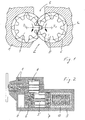
- Figure 1 shows a positive displacement pump in a cross section, in a pump housing 1, a delivery chamber is formed with an inlet 2 on a low pressure side and an outlet 3 on a high pressure side.
- a first conveying member 4 and a second conveying member 5 are movably arranged in the conveying chamber.
- the conveying members 4 and 5 are in a conveying engagement with one another. If the conveying members 4 and 5 are driven, they carry out a conveying movement in the conveying engagement, through which a fluid, for example lubricating oil or a hydraulic fluid, is drawn into the conveying chamber through the inlet 2 and carried out at a higher pressure the outlet 3 is displaced.
- the conveying member 4 is driven and drives the conveying member 5 in the conveying engagement.
- the positive displacement pump of the exemplary embodiment is an external gear pump.
- the conveying members 4 and 5 are externally toothed conveying rotors and the conveying engagement is a tooth engagement.
- the conveyor members 4 and 5 are rotatably mounted about an axis of rotation R 4 and R 5 . In the case of a rotary drive, the sucked-in fluid is transported from the inlet 2 into the conveying cells formed by the tooth gaps in each of the conveying members 4 and 5 through the region of the so-called wrap 1a and expelled through the outlet 3.
- the axial length of the delivery engagement of the delivery members 4 and 5, the engagement length, measured along the axes of rotation R 4 and R 5 is adjustable.
- the conveying member 5 can be moved axially relative to the conveying member 4 and the pump housing 1 between a position of maximum engagement length and correspondingly maximum delivery volume and a position of minimum engagement length and accordingly minimum delivery volume.
- FIG. 2 shows the positive displacement pump in a longitudinal section.
- the conveyor member 4 is secured against rotation on a drive shaft which protrudes from the pump housing 1 and carries a drive wheel for driving the pump.
- the conveying member 5 is part of an adjusting unit which, in addition to the conveying member 5, comprises an actuator with two actuating pistons 6 and 7.
- This adjusting unit 5-7 can be moved axially back and forth as a whole in the pump housing 1 in order to be able to adjust the engagement length.
- the conveying member 5 is arranged axially between the actuating pistons 6 and 7.
- the actuator 6, 7 supports the conveying member 5 so as to be rotatable about the axis of rotation R 5 .
- the adjustment unit 5-7 is in a cylindrical Cavity of the pump housing 1 added.
- the cavity forms an axial track for the movements of the adjustment unit, 5-7. Furthermore, it forms a pressure chamber 8 on one axial side of the adjusting unit 5-7 and a further pressure chamber 9 on the other side.
- the actuating pistons 6 and 7 fluidically separate the two pressure chambers 8 and 9 from one another and also from the delivery chamber, apart from unavoidable leakage losses.
- the pressure chambers 8 and 9 can each be printed with a pressurized fluid, in the exemplary embodiment with the fluid delivered by the displacement pump.
- a pump spring 10 is arranged in the pressure chamber 9, the spring force of which acts on the adjusting unit 5-7, namely on the actuating piston 7, in the direction of the maximum engagement length.
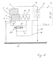
- Figure 3 shows the positive displacement pump integrated in a closed fluid circuit, for example a lubricating oil of a motor vehicle
- the fluid circuit contains a reservoir 11 from which the pump sucks the fluid on the low pressure side through the inlet 2 and with a higher pressure on the high pressure side through the outlet 3, a connected one Supports supply line 12 and via a cooling and cleaning device 13 with a cooler and a filter to the unit 14 to be supplied with the fluid, for example a bee engine for driving a motor vehicle. Downstream of the unit 14, the fluid is fed back into the reservoir 11 through a line 15.
- a partial flow 16 of the fluid is branched off and returned to the pump via an adjustment valve 20.
- the adjustment valve 20 has an inlet for the partial flow 16, an outlet short-circuited with the reservoir 11 and two further connections, one of which is connected to the pressure chamber 8 via a line 18 and the other is connected to the pressure chamber 9 via a line 19.
- the adjusting valve 20 is a multi-way switching valve. In a first switching position, it leads the partial flow 16 into the pressure chamber 8 and connects the pressure chamber 9 to the reservoir II, thus switching the pressure chamber 9 to ambient pressure.
- the adjustment valve 20 of the exemplary embodiment can assume three switch positions, namely the two switch positions mentioned and also a middle position in which it separates the pressure chambers 8 and 9 from one another and also from the reservoir 11 and the partial flow 16, so that the respective pressure in the pressure chambers 8 and 9 is retained, one ignores leaks and the associated leakage losses.
- a 4/3-way valve was selected for the adjusting valve 20.
- FIG 4 shows the adjustment valve 20 as in Figure 3 as a circuit symbol, only in an enlarged cooking position.
- the four connections of the adjustment valve 20 are entered, of which the inlet for the recirculated partial flow 16 is identified by I, the outlet to the reservoir 11 by O, the connection for the pressure chamber 8 by A and the connection for the pressure chamber 9 by B.
- the adjustment valve 20 is a proportional valve with a constantly acting fluidic valve actuating pressure P20, namely the pressure of the fluid returned in the partial flow 16, and a valve spring 25 which is arranged to counteract the valve actuating pressure P 20 .
- the adjusting valve 20 comprises, as a proportional valve, an adjusting device which reverses the adjusting valve 20 from one of the switching positions into another, adapted to the fluid requirement of the unit 14.
- the valve actuating pressure P 20 and the valve spring 25 give the adjusting valve 20 a fail-safe property in the event of failure of the proportional adjusting device.
- the adjustment device is a magnetic adjustment device that is switched with a pulse-width-modulated electrical control signal.
- the control signal is generated by a control device in the form of a square-wave signal with a constant upper and a constant lower signal level, for example voltage level, and a specific period duration.
- the duration of the upper signal level, the so-called switch-on time, and subsequently the time period of the lower signal level, the switch-off time can be varied.
- the magnetic force of the adjusting device changes in accordance with the duty cycle of the control signal, ie the ratio of the switch-on time to the period t.
- the switching position of the adjusting valve 20 results from the balance of forces between the force of the valve spring 25 and the two opposing forces, namely the fluidic force generated by the valve actuating pressure P 20 and the magnetcraft.
- the greater the valve control pressure P 20 the smaller the magnetic force corresponding to the balance of forces. If the sum of the fluidic force and the magnetic force exceeds the spring force, the valve piston 22 moves in the direction of the first switching position, and the delivery volume of the displacement pump is reduced. If the force of the valve spring 25 predominates, the valve piston 22 moves into the second switching position, and the displacement unit 5-7 accordingly moves in the direction of the maximum delivery volume.
- the switch-on time and the switch-off time are assigned to the first and the second switching position of the adjusting valve 20.
- the position of the valve piston 22 and the associated switching position of the adjusting valve 20 are decoupled from the valve actuating pressure P 20 .
- the adjusting valve 20 assumes the first switching position, in which the fluid of the partial flow, during each switch-on time 16 is returned to the pressure chamber 8, and during each switch-off time assumes the second switching position in which the fluid is returned to the pressure chamber 9.
- the flow through the adjusting valve 20 to the respective pressure chamber 8 or 9 can be varied practically continuously in both versions because of the significantly shorter period t of the control signal compared to the relevant time constant of the pump.
- the pressure in the pressure chamber 8 and the pressure in the pressure chamber 9 can also be changed correspondingly continuously.
- the adjustment unit 5-7 can be moved along its axial adjustment path into any axial position and can also be held there.
- the delivery volume is thus flexible between the maximum and the minimum delivery volume and can be continuously and precisely adapted to the fluid requirement of the unit 14.
- a map is stored in an electronic or optical memory in a controller for the unit 14, in the exemplary embodiment of a motor controller, for the supply of the unit 14 in accordance with requirements.
- the characteristic diagram contains in each case a predetermined target value for the fluid supply pressure P 14 or the volume flow V 14 which the unit 14 requires in the respective operating state.
- These volume flow or pressure setpoints are stored in the map as a function of physical variables that characterize the operating states that are to be differentiated with regard to the fluid requirement.
- the temperature T, the speed D and the load L may be mentioned as examples of the physical quantities.
- the unit 14 has a detection device for detecting one or more physical quantity (s) that characterize the different operating states.
- the temperature T can be, for example, at a critical point of the unit 14, in a cooling fluid that serves to cool the unit 14, or in that of the pump 3 pumped fluid can be measured.
- the speed D can be detected very easily by means of a tachometer and the load L via the accelerator pedal or a throttle valve position.
- a setpoint specification selects the assigned pressure or volume flow setpoint on the basis of the characteristic diagram and gives it to the control device for the adjusting valve 20.
- the control device forms the control signal, namely the ratio of the switch-on time to the period t, in accordance with the current setpoint.
- a feedback by means of a controlled variable in the present case a measured actual value of the fluid supply pressure P 14 or the volume flow V 14 , is not necessary as long as the actual eluid requirement of the unit 14 corresponds to the target value.
- the control based on the setpoint can in particular be supplemented by a current control.
- the current control is used, in particular, to compensate for changes in resistance of the magnetic adjusting device, as can occur especially when there are changes in temperature.
- the current consumption of the adjustment device is detected by a detection device and kept at a specific current value. If a change in the current consumption and accordingly the electrical resistance of the adjusting device is determined by means of the detection device, the pulse duty factor is changed in such a way that the current consumption corresponds again to the current value before the resistance change.
- a regulating device is also provided for the adjusting valve 20.
- the control device forms the control signal for the adjusting valve 20 as a function of a target / actual comparison based on a fluid supply pressure P 14 or volume flow V 14 required for the unit 14 .
- the control device has access to a memory in which other setpoints of the pressure P 14 or volume flow V 14 are stored in the form of a map comparable to the map previously used for the control.
- the maps of the pressure setpoints or volume flow setpoints can be stored in physically different memories or in the same memory in different areas.
- a higher-level control device which can be a component of the pressure or volume flow control device or the control device and changes from the control to a control if it is determined that the demand of the unit has changed to such an extent that the characteristic diagram of the setpoints no longer adequately describes the actual demand because the demand has increased due to wear, for example.
- the actually prevailing fluid supply pressure P 14 can be recorded, for example, at the most downstream consumption point of the unit 14 or, in the example of the internal combustion engine, at the engine gallery and compared with the pressure target value relevant for the respective operating state, for example by forming the difference between the target - and actual value.
- the pressure or volume flow control described by way of example as not being feedback can be further developed to a pressure or volume flow control with a target / actual comparison of the respective pressure or volume flow target value with an actual value to be measured for the comparison.
- Several maps for the volume flow V 14 or fluid supply pressure P 14 can be stored in advance, which describe the need for different times in the life cycle of the unit 14, for example one map for the first n kilometers of a motor vehicle or n operating hours of the unit 14, the next m kilometers of the vehicle or m hours of operation of the unit etc. Based on, for example, the mileage of the vehicle or an operating date recording can be switched from the map used first to the next etc. in such embodiments.
- control device can also delay the ability to change the setpoint values of the map according to the state of the unit 14, in order to be able to control the adjusting valve 20 in a better adapted manner to the respective state of the unit 14 on the basis of the changed map.
- the change in the setpoint values of the map or the selection of one of a number of predefined guy fields is advantageously carried out automatically, for example on the basis of the already mentioned mileage or the operating time or a detection of the fluid supply pressure P 14 and comparison with or in the form of a map setpoint pressure setpoint (s) ), such a target / actual comparison could be used for pressure control of the adjusting valve 20, but preferably only for the selection of the pressure or volume flow map to be used or the change in the pressure or volume flow setpoints of a single predetermined map is used for control.
- Figure 5 shows in a longitudinal section a modified with respect to the generation of the valve actuating pressure P 20 valve 20.
- the valve actuating pressure P 20 is different from that of the adjusting valve Figure 4 not by means of an additional partial flow into which Figures 3 and 4 the partial flow 17, but by means of the flow of the partial flow 16 to be controlled or regulated.
- the adjusting valve 20 has a valve housing 21 and a valve piston 22, which can move axially back and forth in the valve housing 21 along a central valve axis S.
- a magnetic coil 27 and an armature 28 made of soft iron are shown by the adjusting device.
- the electrical connections of the solenoid 27 are also indicated.
- the solenoid 27 is fixedly connected to the valve housing 21 and surrounds the armature 28.
- the armature 28 is connected to the valve piston 22 so that it cannot move axially, so that the valve piston 22 and the armature 28 have axial movements such as execute a unit.
- the valve piston 22 has a first active surface 2.3 and a second active surface 24 for the valve control pressure P 20 .
- the active surfaces 2, 3 and 24 axially jointly delimit a fluid space 26 and face each other axially.
- the active surface 23, on which the valve actuating pressure P 20 of the valve spring 25 counteracts, is larger than the active surface 24, wherein in Figure 5 the conditions are exaggerated.
- the difference in size is actually only slight, but is defined in such a way that the valve actuating pressure P 20 on the valve piston 22 always exerts a differential force corresponding to the difference in size of the active surfaces 23 and 24, which counteracts the force of the valve spring 25.
- valve piston 22 can be manufactured very precisely to the size difference of the active surfaces 23 and 24, the differential force can also be correspondingly small and the valve spring 25 advantageously softer than in the exemplary embodiment in FIG Figure 4 his.
- the adjusting device 27, 28 requires correspondingly low forces.
- the adjusting valve 20 becomes more sensitive overall, and the switching times of the adjusting valve 20 can be shortened.
- the inlet I for the fluid to be controlled or regulated opens into the fluid space 26 in all switching positions of the adjusting valve 20.
- the port B opens into the fluid chamber 26, and the valve piston 22 separates the fluid chamber 26 and thus the inlet I from the other port A. Accordingly, the fluid of the partial flow 16 is returned to the pressure chamber 9, while the pressure chamber 8 via the port A is connected to the reservoir 11 and is therefore depressurized.
- the connection A is connected to the outlet O via a space of the valve housing 21, in which the valve spring 25 is arranged, and to the outlet 11 via this.
- the solenoid 27 is energized and moves the armature 28 against the force of the valve spring 25 in the axial direction initially into the middle switching position and, with a correspondingly long switch-on time, into the other extreme switching position , the first switch position.
- the valve piston 22 separates both ports A and B from the fluid chamber 26, into which the inlet I continues to open.
- the valve piston 2.2 assumes an axial position such that the fluid chamber 26 is in axial overlap with both the inlet I and the port A, while the valve piston 22 in the relevant axial position is the port B of the fluid chamber 26 separates fluidically.
- the fluid of the partial flow 16 is conducted through the fluid chamber 26 and the connection A into the pressure chamber 8, while the pressure chamber 9 is connected to the outlet O and finally to the reservoir 11 via the connection B and a passage C of the valve piston 22 is.
- the valve piston 22 is hollow.
- the passage C is formed in a cylindrical jacket region of the valve piston 22, which adjoins the active surface 24 in the direction of the armature 28 and forms a narrow sealing gap with the surrounding jacket of the valve housing 21, which fluidically separates the adjusting device 27, 28 from the fluid chamber 26 ,
- the adjusting device 27, 28 with the associated control device switches the adjusting valve 20 over the entire operating range of the unit 14 and controls or regulates the axial position of the adjusting unit 5-7 and consequently the delivery volume of the displacement pump over the entire volume flow range, which is necessary for the adapted supply of the unit 14 is required.
- the fluidic valve actuating pressure P 20 and the valve spring 25 serve as backup in the event that the adjusting device 27, 28 or the associated control device fails due to a defect, for example due to a cable break or a loose electrical plug connection.
- the adjusting valve 20 is designed such that, in the event of a failure, the delivery volume of the pump from maximum to minimum is only adjusted when a fluid supply pressure P 14 is reached that is greater than a maximum fluid supply pressure P 14 , which is set when the adjusting valve 20 functions properly ,
- the valve spring 25 is installed with a pretensioning force which is greater than a force exerted on the valve piston 22 by a greatest valve actuating pressure P 20 , which can occur when the valve is functioning properly.
Landscapes
- Engineering & Computer Science (AREA)
- Mechanical Engineering (AREA)
- General Engineering & Computer Science (AREA)
- Details Of Reciprocating Pumps (AREA)
- Details And Applications Of Rotary Liquid Pumps (AREA)
- Sliding Valves (AREA)
- Fluid-Driven Valves (AREA)
- Multiple-Way Valves (AREA)
- Magnetically Actuated Valves (AREA)
- Safety Valves (AREA)
Description
- Die Erfindung betrifft ein Verstellventil für die Verstellung des Fördervolumens einer Verdrängerpumpe und eine Verdrängerpumpe mit dem Verstellventil, das für die Verstellung des Fördervolumens eines von der Pumpe zu fördernden Fluids in einem Fluidkreis der Pumpe angeordnet ist. Die Erfindung betrifft demgemäß auch das Verstellventil als solches, soweit es für die Verstellung des Fördervolumens einer Verdrängerpumpe vorgesehen ist.
- Die Druckschrift
US 5 876 185 A , die als nächstliegender Stand der Technik angesehen wird, offenbart ein Verstellventil mit einem Ventilkolben, der bei steigendem Ventilstelldruck gegen die Kraft einer Ventilfeder bewegt wird. Mit diesem Ventil kann eine verstellbare Pumpe geregelt werden. - Verdrängerpumpen fördern Fluide mit einem zur Pumpengeschwindigkeit proportionalen Volumenstrom. Das Fördervolumen pro Umdrehung oder hin und her gehenden Hub, der so genannte spezifische Volumenstrom, ist konstant oder kann in der Praxis zumindest in guter Näherung als konstant betrachtet werden. Die Konstanz pro Umdrehung oder Hub und dementsprechend die Proportionalität zur Pumpengeschwindigkeit ist beispielsweise in Anwendungen störend, in denen das von der jeweiligen Pumpe zu versorgende Aggregat einen Fluidbedarf hat, der in einem oder mehreren Geschwindigkeitsbereich(en) der Pumpe geringer ist als der sich aus der Proportionalität ergebende Volumenstrom. In dem jeweiligen Geschwindigkeitsbereich fördert die Pumpe dementsprechend einen über dem Bedarf liegenden Volumenstrom, der verlustbehaftet abgeleitet wird. Die Problematik wird in der
US 6 126 420 B beschrieben, die zur Lösung des Problems bereits eine Innenzahnradpumpe mit verstellbarem Fördervolumen offenbart. - Die
US 6 244 839 B1 offenbart ebenfalls eine Innenzahnradpumpe mit verstellbarem Fördervolumen. Für die Verstellung ist das innere Zahnrad relativ zu dem äußeren Zahnrad axial verschiebbar. Das innere Zahnrad ist Bestandteil einer axial verschiebbaren Verstelleinheit, die als beidseitig wirkender Kolben gebildet ist. Die Verstelleinheit wird über ein 4/3-Verstellventil mit dem von der Pumpe geförderten Fluid beaufschlagt. Das Verstellventil weist ein Ventilgehäuse und einen im Ventilgehäuse axial hin und her bewegbaren Ventilkolben auf, der an einem axialen Ende mit dem geförderten Fluid und am anderen axialen Ende mit einer dem Druck des Fluids entgegenwirkenden Kraft einer Ventilfeder beaufschlagt wird. Die Stellung des Ventilkolbens stellt sich entsprechend dem Gleichgewicht der Kraft der Ventilfeder und der vom Fluiddruck erzeugten Kraft ein. Das Verstellventil ist so ausgelegt, dass sich die Verstelleinheit der Pumpe bei Erreichen eines durch die Ventilfeder vorgegebenen Fluiddrucks aus einer Axialposition für maximales Fördervolumen in Richtung auf eine Axialposition für minimales Fördervolumen bewegt. Die Vorspannkraft der Ventilfeder wird am Verstellventil im Vorhinein eingestellt. - Aus der
WO 03/058071 A1 - Aus der
DE 103 24 092 A1 5 ist eine regelbare Schmierölpumpe mit einem Fördermengenregler bekannt. Der Fördermengenregler umfasst ein Ventil mit einem in axial beweglichen Regelkolben. Der Regelkolben arbeite gegen die Kraft einer Feder, die an der dem Regelkolben abgewandten Seite an einer Vorrichtung abgestützt ist, die es erlaubt, den Federweg des Regelkolbens zu verlängern oder die Federkraft der Feder zu verstellen. DieEP 1 555 436 A2 beschreibt eine Zahnradpumpe mit Fördermengenregelung mit einem Ventil, dessen Durchgangsöffnung durch ein Steuergerät verändert werden kann. Bei dem Ventil handelt es sich um ein pulsbreitenmodeliertes Magnetventil, das zur Fördermengenregelung über einen mit der ersten Druckkammer der Pumpe verbundenen Druckumwandler mit einem mit diesem gekoppelten Steuergerät wirkverbunden ist. Aus derDE 102005 029 086 A1 ist eine Ölpumpe für eine Brennkraftmaschine mit einem Verstellventil bekannt. Das Ventil ist ein elektrisch ansteuerbares Ventil und umfasst einen im Ventil axial beweglichen Ventilkörper mit Abschnitten unterschiedlichen Durchmessers, bei deren Verschiebung langlochförmige Steueröffnungen des Ventils freigegeben oder verschlossen werden. DieDE 31 09 045 A1 beschreibt eine regelbare Hydraulikpumpe mit einem Regelventil. Bei dem Ventil handelt es sich um ein 3/2-Wege-Ventil, dessen Schalten durch Wirkung von Fluiddruck auf die Stirnfläche eines im Ventil beweglich gelagerten Schieberkolbens bewirkt wird. DieJP 57 131890 A US 7 726948 B2 ,US 6 244 839 B1 undFR 2 326 600 A - Es ist eine Aufgabe der Erfindung, das Fördervolumen einer Verdrängerpumpe flexibel und genau an den Bedarf eines zu versorgenden Aggregats anzupassen und eine ausreichende Versorgung des Aggregats stets zu gewährleisten.
- Die Erfindung geht von einer Verdrängerpumpe für die Versorgung eines Aggregats mit Fluid aus, die ein Pumpengehäuse mit einer Förderkammer und ein in der Förderkammer bewegliches Förderglied aufweist, dass unmittelbar auf das Fluid wirkt, um dieses durch die Förderkammer zu fördern. Das Förderglied kann bei Ausführung einer Förderbewegung das Fluid alleine oder im Zusammenwirken mit einem oder gegebenenfalls auch mehreren weiteren Förderglied(ern) von einem Einlass der Förderkammer unter Erhöhung des Drucks durch einen Auslass der Förderkammer fördern. Der Einlass wird einer Niederdruckseite und der Auslass wird einer Hochdruckseite der Pumpe zugeordnet. Die Pumpe ist vorzugsweise in einem geschlossenen Fluidkreis angeordnet, kann grundsätzlich jedoch auch der Förderung des Fluids in einem offenen Fluidkreis dienen. Bei Integration in einem geschlossenen Fluidkreis saugt sie das Fluid auf der Niederdruckseite aus einem Reservoir durch den Einlass in die Förderkammer und fördert es auf der Hochdruckseite zu dem oder gegebenenfalls auch mehreren mit dem Fluid zu versorgenden Aggregat(en). Stromabwärts von dem oder den Aggregat(en) gelangt das Fluid wieder in das Reservoir, wodurch sich der Fluidkreis schließt. Die Pumpe kann beispielsweise für die Versorgung einer hydraulischen Presse mit Druckfluid verwendet werdell. In bevorzugten Ausführungen ist sie in einem Kraftfahrzeug eingebaut oder für den Einbau vorgesehen, um eine das Kraftfahrzeug antreibende Brennkraftmaschine mit Schmierfluid oder ein Automatikgetriebe mit Hydraulikflüssigkeit zu versorgten. Vorzugsweise treibt die Brennkraftmaschine die Pumpe an.
- Die Verdrängerpumpe umfasst ferner ein Verstellventil, mittels dem das Fördervolumen der Pumpe angepasst an den Bedarf des wenigstens einen zu versorgenden Aggregats verstellt und die für den Antrieb der Pumpe erforderliche Energie vorzugsweise entsprechend reduziert werden kann. Das Verstellventil umfasst ein Ventilgehäuse, einen in dem Ventilgehäuse beweglichen Ventilkolben, eine Ventilfeder und eine Verstelleinrichtung. Der Ventilkolben weist eine Wirkfläche für einen fluidische Ventilstelldruck auf. Die Ventilfeder ist so angeordnet, dass sie dem insgesamt auf den Ventilkörper, wirkenden Ventilstelldruck entgegen auf den Ventilkolben wirkt.
- Als Fördervolumen wird in bevorzugten Ausführungsformen der spezifische Volumenstrom der Pumpe als solche verstanden, im Falle einer Rotationspumpe der Volumenstrom pro Umdrehung und im Falle einer Hubkolbenpumpe der Volumenstrom pro Hub. Obgleich weniger bevorzugt kann die Pumpe auch eine Konstantpumpe und das Verstellventil kann auf der Hochdruckseite der Pumpe als Bypassventil angeordnet sein, um überschüssig gefördertes Fluid unter Umgehung des wenigstens einen Aggregats in das Reservoir zu fördern. Durch solch eine Bypassförderung wird zwar nicht der Energieverbrauch der Pumpe reduziert, aber immer noch eine bedarfsgerechte Förderung sichergestellt. Es wird in derartigen Ausführungen nicht das Fördervolumen am Auslass der Förderkammer, sondern das zu dem wenigstens einen Aggregat geförderte Fördervolumen bedarfsgerecht gesteuert oder geregelt. Es kann auch eine in ihrem Fördervolumen verstellbare Pumpe mit solch einem Bypassventil kombiniert werden, indem der Volumenstrom pro Umdrehung oder Hub über ein erfindungsgemäßes Verstellventil oder in anderer Weise verstellt und stromabwärts von der Pumpe, aber stromaufwärts von dem zu versorgenden Aggregat, ein Teil des von der Pumpe geförderten Volumenstroms abgezweigt und ungenutzt in ein Reservoir zurückgeieitet wird. In bevorzugten Ausführungsformen wird das Fördervolumen der Pumpe als solche, gesehen unmittelbar am Auslass der Förderkammer, mittels des Verstellventils verstellt. In derartigen Ausführungen ist in dem Pumpengehäuse ein Stellglied bewegbar angeordnet, das in Richtung seiner Bewegbarkeit mit einer von dem Bedarf des wenigstens einen Aggregats abhängigen Stellkraft beaufschlagbar ist. Das Stellglied kann insbesondere zu einer Stirnseite des Förderglieds oder das Förderglied umgebend angeordnet sein. Das Stellglied und das Förderglied sind in ersten Varianten Bestandteil einer in dem Pumpengehäuse als Gesamtheit hin und her bewegbaren Verstelleinheit, beispielsweise einer linear beweglichen oder schwenkbaren oder anders quer zu einer Drehachse des bevorzugt drehbaren Förderglieds beweglichen Verstelleinheit. Beispiele derartiger Verstelleinheiten beschreiben beispielsweise die
US 6 28.3 735 B1 für außenachsige, dieUS 6 126 420 B undUS 6 244 8.39 B1 für innenachsige Pumpen In zweiten Varianten ist das Stellglied relativ zu dem Förderglied und dem Pumpengehäuse verstellbar. Das Stellglied der zweiten Variante kann insbesondere ein das Förderglied umgebender Stellring sein, wie dies von Flügelpumpen einschließlich Flügelzellenpumpen, Pcndelschieberpumpen und auch von Innenzahmradpumpen bekannt ist, um die Exzentrizität zum Förderglied zu verstellen, beispielsweise durch eine lineare Hub- oder eine Schwenkbewegung des Stellglieds. - Die Stellkraft wird vorzugsweise fluidisch erzeugt, indem das Stellglied einen Stellkolben bildet, der mit einem Druckfluid beaufschlagt wird. Dieses Druckfluid kann insbesondere auf der Hochdruckseite der Pumpe abgezweigt und als Teilstrom des von der Pumpe insgesamt geförderten Volumenstroms über das Verstellventil auf das Stellglied zurückgeführt werden. Das Druckfluid, mit dem das Stellglied beaufschlagt wird, kann grundsätzlich jedoch auch ein anderes Fluid sein, beispielsweise ein Fluid, das aus einem Druckreservoir oder von einer anderen Pumpe bereitgestellt wird.
- In noch einer Variante wird ein Teilstrom des Fluids über das Verstellventil in die Förderkammer zurück zu der Niederdruckseite geführt, um dort den Füllgrad von Förderzellen zu steigern, wie dies beispielsweise in der
US 6 9.35 851 B2 offenbart wird Durch die Rückführung und Befüllung der Förderzellen wird gleichzeitig auch das Fördervolumen verstellt, wobei diese Art der Verstellung mit einer der bereits genannten anderen Arten auch in Kombination verwirklicht sein kann. - Nach der Erfindung wird die Verstelleinriclltullg so gebildet, dass sie den Ventilkolben in Richtung der von dem Ventilstelldruck auf den Ventilkörper ausgeübten Kraft oder gegen den Ventilstelldruck verstellen kann. Sie wirkt vorzugsweise elektromagnetisch Das Wort "oder" umfaßt hier wie auch überfall sonst im Sinne der Erfindung die Bedeutung von "entweder .........oder" und auch die Bedeutung von "und", soweit sich aus dem jeweiligen Zusammenhang nicht unumgänglich eine eingeschränkte Bedeutung umgibt. Die VerStelleinrichtung kann dementsprechend so konstruiert sein, dass sie der Kraft des Ventilstelldrucks nur entgegenwirkt oder vorzugsweise nur in die gleiche Richtung und der Ventilfeder entgegenwirkt, und sie kann alternativ auch so konstruiert sein, dass sie sowohl in als auch gegen die Kraft des Ventilstelldrucks den Ventilkolben verstellen kann.
- In einer bevorzugten ersten Ausführungsform wirken der Ventilstelldruck und eine von der Verstelleinrichtung auf den Ventilkolben ausgeübte Kraft gemeinsam gegen die Kraft der Ventilfeder. Steigt der Ventilstelldruck, kann der Ventilkolben mittels einer entsprechend kleineren Kraft der Verstelleinrichtung gegen die Kraft der Ventilfeder verstellt werden.
- In einer zweiten bevorzugten Ausführungsform ist die Verstelleinrichtung für eine Verstellung des Ventilkolbens sowohl in Richtung des Ventilstelldrucks als auch gegen den Ventilstelldruck eingerichtet. Handelt es sich bei der Verstelleinrichtung um eine Magnetverstelleinrichtung mit nur einer einzigen Magnetspule, so ist in derartigen Ausführungsformen die Magnetspule umpolbar. Alternativ kann für jede von zwei Richtungen der Bewegbarkeit des Ventilkolben eine eigene Magnetspule mit jeweils einem Anker vorgesehen sein und der eine dieser Anker auf den Ventilkolben eine Kraft in die eine und der andere Anker eine Kraft in die andere Richtung der Bewegbarkeit des Ventilkolbens ausüben, um den Ventilkolben hin und her zu bewegen.
- Die Position des Ventilkolbens kann relativ zum Ventilgehäuse somit zumindest in der zweiten Ausführungsform, vorzugsweise aber auch in der ersten Ausführungsform unabhängig von dem auf die Wirkflächen wirkenden Ventilstelldruck verstellt, und das Fördervolumen der Pumpe kann dementsprechend eingestellt werden. Das Verstellventil kann somit das Fördervolumensüber einen größeren Betriebsbereich des zu versorgenden Aggregats kontinuierlich oder beliebig gestuft angepasst einstellen und nicht nur auf einen bestimmten Druck, bei dessen Erreichen das Fördervolumen abgeregelt wird.
- Nach der Erfindung ist eine Steuerungs- oder Regelungseinrichtung für das Verstellventil so eingerichtet, dass mittels des Verstellventils das Fördervolumen über den gesamten Betriebsbereich des Aggregats angepasst verstellbar ist. Andererseits gewährleisten die Ventilfeder und der ständig der Kraft der Ventilfeder entgegenwirkende Ventilstelldruck eine sichere Versorgung des Aggregats, wenn auch bei Ausfall der VerStelleinrichtung nur noch wie von herkömmlichen Verdrängerpumpen bekannt mit einer Abregelung des Fördervolumens in Abhängigkeit von der Vorspannkraft und Federkonstanten der Ventilfeder. Die Erfindung kombiniert eine genaue und flexible Anpassbarlceit an den Bedarf mit einer auch bei Ausfall der Verstelleinrichtung gewährleisteten Versorgungssicherheit, sie schafft eine sogenannte Second-Level-Steuerung oder -regelung für das Fördervolumen.
- Das Verstellventils ist vorzugsweise ein Proportionalventil. Es wird vorzugsweise elektrisch angesteuert. Die Verstelleinrichtung wirkt vorzugsweise magnetisch. Sie kann eine Proportionalmagnetspule aufweisen, die spannungs- oder stromgesteuert oder -geregelt wird, also durch eine am Bedarf des wenigstens einen Aggregats orientierte Variation der angelegten Spannung oder des elektrischen Stroms. In anderen bevorzugten Ausführungen wird das Verstellventil pulsmoduliert gesteuert oder geregelt, Bei Verwendung eines pulsmodulierten Verstellventils kann die Dauer der einzelnen Pulse oder der zeitliche Abstand zwischen zwei aufeinander folgenden Pulsen der Stellgröße variiert werden, was auch den Fall einschließt, dass sowohl die Pulsdauer als auch die Zeitdauer zwischen aufeinander folgenden Pulsen angepasst an den Bedarf variiert wird. Die Periodendauer der Stellgröße ist vorzugsweise konstant. Bevorzugt wird ein pulsweitenmoduliertes Verstellventil verwendet. Die Periodendauer der Stellgröße für das Verstellventil ist deutlich kleiner als die für die Verstellung des Fördervolumens bestimmende Zeitkonstante der Verdrängerpumpe. Die Pulsmodulation bedient sich des Tiefpasscharakters der Pumpe. Indem die Einschaltzeit der Pulsweitenmodulation oder der Zeitabstand im Falle einer Pulsfrequenzmodulation angepasst an den Bedarf variiert wird, kann der Durchfluss durch das Verstellventil und infolgedessen das Fördervolumen der Verdrängerpumpe quasi kontinuierlich dem momentanen Bedarf des Aggregats entsprechend gesteuert oder geregelt werden.
- Das Veistellventil ist vorzugsweise ein Mehrwegeventil mit wenigstens drei Anschlüssen, bevorzugt mit vier Anschlüsse. Es ist vorzugsweise zwischen wenigstens zwei Schaltstellungen, bevorzugt zwischen drei Schaltstellungen, umschaltbar.
- Das Verstellventil wird in bevorzugten Ausführungen in Abhängigkeit von einem Sollwert für den von der Verdrängerpumpe zu fördernden Volumenstroms oder einen von der Verdrängerpumpe zu erzeugenden Fluidversorgungsdruck gesteuert oder geregelt. Eine Sollwertvorgabe gibt den Sollwert einer für das Verstellventil vorgesehenen Steuerungs- oder Regelungseinrichtung vor. Der Sollwert wird vorzugsweise in Abhängigkeit von dem Bedarf des Aggregats variiert. Vorzugsweise wird ein Kennfeld für die vom Betriebszustand des Aggregats abhängigen Sollwerte vorgegeben. Der wenigstens eine Sollwert oder bevorzugter die mehreren Sollwerte wird oder werden in Abhängigkeit von einer für den Betriebszustand kennzeichnenden physikalischen Größe vorgegeben, die während des Betriebs des Aggregats mittels einer Erfassungseinrichtung sensorisch ermittelt wird. Die wenigstens eine physikalische Größe kann insbesondere eine Temperatur, eine Drehzahl oder ein Lastzustand des Aggregats sein. Bevorzugt wird der Sollwert oder werden die Sollwerte tür den Volumenstrom oder den Fluidversorgungsdruck in Abhängigkeit von wenigstens zwei den Betriebszustand des Aggregats kennzeichnenden Größen vorgegeben. Wird die Verdrängerpumpe als Schmierölpumpe für eine Brennkraftmaschine verwendet, kann oder können sensorisch beispielsweise die Temperatur des Schmieröls oder der Kühlflüssigkeit im Bereich der Brennkraftmaschine oder die Drehzahl oder für den Lastzustand die Gaspedal- oder eine Drosselklappenstellung erfasst und daraus anhand des Kennfelds der zugehörige Sollwert ermittelt und der Steuerungs- oder Regelungseinrichtung für das Verstellventil vorgegeben werden.
- In einer bevorzugten ersten Ausführungsform wird das Verstellventil in Abhängigkeit von dem jeweiligen Sollwert nur gesteuert. Auf die Erfassung eines für den Bedarf repräsentativen Istwerts der den Sollwert bildenden physikalischen Größe, nämlich des Volumenstroms oder des Fluidversorgungsdrucks, wird verzichtet, ebenso auf eine aufwendige Verarbeitung für eine Regelung anhand eines Soll/Ist-Vergleichs.
- In einer ebenfalls bevorzugten zweiten Ausführungsform wird das Verstellventil in Abhängigkeit von einem Soll/Ist-Vergleich des jeweiligen Sollwerts und eines kontinuierlich oder in ausreichend kleinen Zeitabständen gemessenen Istwerts des Volumenstroms oder des Fluidversorgungsdrucks geregelt. Eine Regelung ist in solchen Fällen von Vorteig, in denen sich der Volumenstrombedarf des Aggregats wegen Verschleiß im Verlaufe der Lebensdauer des Aggregats ändert.
- In einer optionalen Kombination der beiden Ausführungsformen ist eine Kontrolleinrichtung vorgesehen, die von einer Steuerung gemäß der ersten Ausführungsform auf eine Regelung gemäß der zweiten Ausführungsform umstellen kann. Bevorzugt wird dabei, wenn das Verstellventil zunächst anhand des vorgegebenen Volumenstroms gesteuert und bei zunehmenden Leckverlusten in Folge eines Verschleißes des Aggregats später auf eine Druckregelung umgestellt wird. In noch einer weiteren Ausführungsform ist eine leitfähige Kontrolleinrichtung vorgesehen, die anhand einer sensorische Erfassung des Volumenstroms oder Fluidversorgungsdrucks zunehmenden Verschleiß feststellt und den Sollwert oder das Sollwert- Kennfelds angepasst wenigstens einmal oder in mehreren Stufen, gegebenenfalls kontinuierlich während der Lebensdauer des Aggregats verschiebt.
- In noch einer bevorzugten Ausführungsform wird das Verstellventil zum einen anhand eines Sollwerts oder eines Sollwert-Kennfelds für den Fluidversorgungsdruck oder den Volumenstrom gesteuert und zusätzlich stromgercgelt, Eine besonders bevorzugte Ausführung ist ein anhand eines Sollwerts oder mehrerer Sollwerte bzw. eines Sollwert-Kennfelds für den Fluidversorgungsdruck oder den Volumenstrom mittels Pulsweitenmodulation gesteuertes und zusätzlich stromgeregeltes Verstellventil. Mit der Stromregelung werden vorteilhafterweise mit Temperaturänderungen einhergellende Änderungen des elektrischen Widerstands einer Magnetverstelleinrichtung ausgeglichen. Es wird die Stromaufnahme der Magnetverstelleinrichtung erfasst und die Änderungen in der Größe des elektrischen Stroms aufgrund von Widerstandsänderungen ausgeglichen, indem das Tastverhältnis der Variation der Stromaufnahme entsprechend geregelt wird. Entsprechend kann jedoch nicht nur für die bevorzugte Ausführung als pulsweitenmoduliertes Verstellventil, sondern auch bei anders gesteuerten Verstellventilen verfahren werden. Durch eine Stromregelung zusätzlich zur Steuerung anhand eines Sollwerts oder Sollwert-Kennfelds für den Volumenstrom oder den Fluidversorgungsdruck kann auf eine Volumenstrom- oder Druckregelung verzichtet werden, obgleich auch im Falle einer Stromregelung zusätzlich eine Volumenstrom- oder Druckregelung zum Einsatz gelangen kann.
- Die Steuerung- oder Regelungseinrichtung kann integrierter Bestandteil des Verstellventil oder separat von diesem eingebaut sein. Die Sollwertvorgabe kann gegenständlicher Bestandteil der Steuerungs- oder Regelungseinrichtung oder gegenständlich separat von den anderen Teilen der Steuerungs- oder Regelungseinrichtung verwirklicht sein. Das Verstellventils ist vorzugsweise integrierter Bestandteil der Verdrängerpumpe, beispielsweise am Pumpengehäuse montiert. Das Verstellventils kann in der integrierten Ausführung vorteilhafterweise auch im Gehäuse der Verdrängerpumpe angeordnet sein, beispielsweise in einer Aufnahmebohrung oder einem andersartig geformten Aufnahmeraum in einer Wand des Pumpengehäuses. Die Anschlüsse des Verstellventils können in derartigen Ausführungen raum- und gewichtssparend als Bohrungen oder anders geformte Kanäle im Gehäuse, insbesondere in besagter Gehäusewand geformt sein, Das Pumpengehäuse kann dementsprechend gleichzeitig auch das Ventilgehäuse oder auch nur einen Teil des Ventilgehäuses bilden.
- In den Ausführungsformen, in denen das Fördervolumen unmittelbar der Pumpe verstellt wird, ist es vorteilhaft, wenn das Stellglied als doppeltwirkender Stellkolben gebildet ist mit zwei axial voneinander abgewandten, vorzugsweise einander abgewandt gegenüberliegenden Kolbenflächen und mittels des Verstellventils entweder die eine oder die andere Kolbenfläche mit einem unter Druck stehenden Druckfluid beaufschlagt werden kann, gegebenenfalls auch beide Kolbenflächen gleichzeitig.
- Bildet das Stellglied einen mit Druckfluid beaufschlagbaren Stellkolben, beispielsweise einen nur einseitig mit Druckfluid beaufschlagbaren oder vorzugsweise einen doppeltwirkenden Kolben, wird es in bevorzugten Ausführungen von einer Pumpenfeder mit einer Federkraft beaufschlagt, wobei die Pumpenfeder in Richtung auf eine Vergrößerung des Fördervolumens der Pumpe wirkt. Bildet das Stellglied einen doppeltwirkenden Kolben, wird es bevorzugt, wenn die Pumpenfeder so schwach ist, dass die Verstelldynamik der Pumpe nicht maßgeblich durch die Pumpenfeder beeinflusst wird, sondern ausschließlich oder zumindest zu einem deutlich überwiegenden Teil durch das Verstellventil. Grundsätzlich kann auf eine Pumpenfeder in derartigen Ausführungen auch verzichtet werden. Andererseits ist die Verwendung einer schwachen Pumpenfeder von Vorteil, wobei solch eine Pumpenfeder so ausgelegt ist, dass sie nur sicherstellt, dass bei mit geringer Geschwindigkeit laufender Verdrängerpumpe das für diese Pumpengeschwindigkeit maximale Fördervolumen gefördert wird. Es genügt eine Pumpenfeder, die auf das Stellglied eine Federkraft entsprechend einem Fluiddruck von höchstens 1 bar ausübt.
- Bevorzugt erzeugt das mittels des Verstellventils gesteuert oder geregelt zu der Verdrängerpumpe zwecks Verstellung geführte Fluid oder im Falle eines nur als Bypassventil verwendeten Verstellventils das zu einem Reservoir abgezweigte Fluid bei seinem Durchfluss durch das Verstellventils den Ventilstelldruck. In derartigen Ausführungen wird für die Erzeugung des Ventilstelldrucks kein separater Ansclaluss benötigt. Der gleiche Einlass, durch den der das Verstellventils durchströmende Fluidstrom in das Verstellventil gelangt, bildet auch den Anschluss für das den Ventilstelldruck erzeugende Fluid.
- Bevorzugt wird es, wenn der Ventilstelldruck mittels mehrerer Wirkflächen, vorzugsweise mittels genau zwei Wirkflächen erzeugt wird, die sich der Größe nach unterscheiden, so dass der Ventilstelldruck auf den Ventilkolben, eine Differenzkraft entsprechend der Flächendifferenz der Wirkflächen ausübt. Besonders bevorzugt wird das Merkmal der Differenzkraft mit dem weiteren Merkmal kombiniert, wonach das Fluid bei dem Durchströmen des Verstellventils gleichzeitig auch den Ventilstelldruck erzeugt.
- In einer Weiterbildung kann die Vorspannkraft der Ventilfeder verstellt werden, bevorzugt fluidisch während die Verdrängerpumpe das Fluid fördert. So kann das Verstellventil einen weiteren Kolben aufweisen der vorzugsweise nur der Einstellung der Vorspannkraft dient und vorzugsweise mit dem Fluid beaufschlagt wird, das auch den Ventilstelldruck erzeugt. wobei für den Kolben zur Verstellung der Vorspannkraft ein separater Anschluss vorgesehen oder vorzugsweise eine auf diesen Verstellkolben wirkende Kraft ebenfalls von dem durchströmenden Fluid erzeugt werden kann.
- Vorteilhafte Merkmale werden auch in den Unteransprüchen und deren Kombinationen beschirieben.
- Nachfolgend wird ein Ausführungsbeispiel der Erfindung anhand von Figuren erläutert. An dem Ausfuhrungsbeispiel offenbar werdende Merkmale bilden je einzeln und in jeder Markmalskombination die Gegenstände der Ansprüche und auch die vorstehend beschriebenen Ausgestaltungen vorteilhaft weiter. Es zeigen:
- Figur 1
- eine Verdrängerpumpe in einem Querschnitt,
- Figur 2
- die Verdrängerpumpe in einem Längsschnitt,
- Figur 3
- die Verdrängerpumpe mit einem Verstellventil für die Verstellung des Fördervolumens der Pumpe,
- Figur 4
- das Verstellventil einzeln als Schaltzeichen und
- Figur 5
- das Verstellventils in einem Längsschnitt.
-
Figur 1 zeigt eine Verdrängerpumpe in einem Querschnitt, In einem Pumpengehäuse 1 ist eine Förderkammer mit einem Einlass 2 auf einer Niederdruckseite und einem Auslass 3 auf einer Hochdruckseite gebildet. In der Förderkammer sind ein erstes Förderglied 4 und ein zweites Förderglied 5 beweglich angeordnet. Die Förderglieder 4 und 5 sind miteinander in einem Fördereingriff Werden die Förderglieder 4 und 5 angetrieben, führen sie im Fördereingriff eine Förderbewegung aus, durch die ein Fluid, beispielsweise Schmieröl oder eine Hydraulikflüssigkeit, durch den Einlass 2 in die Förderkammer gesogen und mit höherem Druck durch den Auslass 3 verdrängt wird. Das Förderglied 4 wird angetrieben und treibt das Förderglied 5 im Fördereingriff an. - Die Verdrängerpumpe des Ausführungsbeispiels ist eine Außenzahnradpumpe. Die Förderglieder 4 und 5 sind dementsprechend außen umlaufend verzahnte Förderrotoren und der Fördereingriff ein Zahneingriff. Die Förderglieder 4 und 5 sind um je eine Drehachse R4 und R5 drehbar gelagert. Bei einem Drehantrieb wird das angesaugte Fluid vom Einlass 2 in bei jedem der Förderglieder 4 und 5 von den Zahnlücken gebildeten Förderzellen durch den Bereich der so genannten Umschlingung la transportiert und durch den Auslass 3 ausgestoßen.
- Um das Fördervolumen der Pumpe dem Bedarf eines mit dem Fluid zu versorgenden Aggregats anpassen zu können, ist die längs den Drehachsen R4 und R5 gemessene axiale Länge des Fördereingriffs der Förderglieder 4 und 5, die Eingriffslänge, verstellbar. Für die Verstellung ist das Förderglied 5 relativ zu dem Förderglied 4 und dem Pumpengehäuse 1 axial zwischen einer Position maximaler Eingriffslänge und dementsprechend maximalen Fördervolumens und einer Position minimaler Eingriffslänge und dementsprechend minimalen Fördervolumens hin und her bewegbar.
-
Figur 2 zeigt die Verdrängerpumpe in einem Längsschnitt. Das Förderglied 4 ist verdrehgesichert auf einer Antriebswelle befestigt, die aus dem Pumpengehäuse 1 hinausragt und ein Antriebsrad für den Antrieb der Pumpe trägt. Das Förderglied 5 ist Bestandteil einer Verstelleinheit, die über das Förderglied 5 hinaus ein Stellglied mit zwei Stellkolben 6 und 7 umfasst. Diese Verstelleinheit 5-7 ist als Gesamtheit im Pumpengehäuse 1 axial hin und her bewegbar, um die Eingriffslänge verstellen zu können. Das Förderglied 5 ist axial zwischen den Stellkolben 6 und 7 angeordnet. Das Stellglied 6, 7 lagert das Förderglied 5 um die Drehachse R5 drehbar. Die Verstelleinheit 5-7 ist in einem zylindrischen Hohlraum des Pumpengehäuses 1 aufgenommen. Der Hohlraum bildet eine axiale Laufbahn für die Bewegungen der Verstelleinheit, 5-7. Des Weiteren bildet er an einer axialen Seite der Verstelleinheit 5-7 einen Druckraum 8 und an der anderen Seite einen weiteren Druckraum 9. Die Stellkolben 6 und 7 trennen die beiden Druckräume 8 und 9 von unvermeidlichen Leckverlusten abgesehen fluidisch voneinander und auch von der Förderkammer. Die Druckräume 8 und 9 sind jeweils mit einem unter Druck stehenden Fluid, im Ausführungsbeispiel mit dem von der Verdrängerpumpe geförderten Fluid bedruckbar. In dem Druckraum 9 ist eine Pumpenfeder 10 angeordnet, deren Federkraft auf die Verstelleinheit, 5-7, nämlich auf den Stellkolben 7, in Richtung maximaler Eingriffslänge wirkt. -
Figur 3 zeigt die Verdrängerpumpe integriert in einen geschlossenen Fluidkreis, beispielsweise einen Schmierölheis eines Kraftfahrzeugs, Der Fluidkreis enthält ein Reservoir 11, aus dem die Pumpe das Fluid auf der Niederdruckseite durch den Einlass 2 ansaugt und mit höherem Druck auf der Hochdruckseite durch den Auslass 3, eine angeschlossene Versorgungsleitung 12 und über eine Kühl- und Reinigungseinrichtung 13 mit einem Kühler und einem Filter zu dem mit dem Fluid zu versorgenden Aggregat 14, beispielsweise eine Biennkraftmaschine für den Antrieb eines Kraftfahrzeugs, fördert. Stromabwärts von dem Aggregat 14 wird das Fluid durch eine Leitung 15 zurück in das Reservoir 11 geführt. - Stromabwärts von der Kühl- und Reinigungseinrichtung 13, insbesondere stromabwärts von dem Reinigungsteil der Kühl- und Reinigungseinrichtung 1.3, aber noch stromaufwärts von dem Aggregat 14 wird ein Teilstrom 16 des Fluids abgezweigt und über ein Verstellventil 20 zu der Pumpe zurückgeführt. Das Verstellventil 20 weist einen Einlass für den Teilstrom 16, einen mit dem Reservoir 11 kurzgeschlossenen Auslass und zwei weitere Anschlüsse auf, von denen der eine über eine Leitung 18 mit dem Druckraum 8 und der andere über eine Leitung 19 mit dem Druckraum 9 verbunden ist. Das Verstellventil 20 ist ein Mehrwege-Scllaltventll, In einer ersten Schaltstellung führt es den Teilstrom 16 in den Druckraum 8 und verbindet den Druckraum 9 mit dem Reservoir I I, schaltet den Druckraum 9 also auf Umgebungsdruck. In einer zweiten Schaltstellung, die das Verstellventil in
Figur 3 einnimmt, kehrt es diese Verhältnisse um, indem es den Teilstrom 16 in den Druckraum 9 führt und den Druckraum 8 mit dem Reservoir 11 kurzschließt. Das Verstellventil 20 des Ausführungsbeispiels kann drei Schaltstellungen einnehmen, nämlich die beiden genannten Schaltstellungen und ferner eine Mittelstellung, in der es die Druckräume 8 und 9 voneinander und auch von dem Reservoir 11 und dem Teilstrom 16 trennt, so dass der jeweilige Druck in den Druckräumen 8 und 9 erhalten bleibt, sieht man von Leckagen und damit verbundenen Leckverlusten ab. Im Ausführungsbeispiel wurde für das Verstellventil 20 ein 4/3-Wegeventil gewählt. -
Figur 4 zeigt das Verstellventil 20 wie inFigur 3 als Schaltzeichen, lediglich in vergrößerter Garstellung. Eingetragen sind die vier Anschlüsse des Verstellventils 20, von denen der Einlass für den zurückgeführten Teilstrom 16 mit I, der Auslass zum Reservoir 11 mit O, der Anschluss für den Druckraum 8 mit A und der Anschluss für den Druckraum 9 mit B bezeichnet sind. - Das Verstellventil 20 ist ein Proportionalventil mit einem ständig wirkenden fluidischen Ventilstelldruck P20, nämlich dem Druck des im Teilstroms 16 zurückgeführte Fluids, und einer Ventilfeder 25, die dem Ventilstelldruck P20 entgegen wirkend angeordnet ist. Der fluidische Ventilstelldruck P20 und die Kraft der Ventilfeder 25 allein bestimmen bei ordnungsgemäßer Funktion des Verstellventils 20 jedoch nicht dessen Schaltstellung. Das Verstellventil 20 umfasst als Proportionalventil eine Verstelleinrichtung, die das Verstellventil 20 angepasst an den Fluidbedarf des Aggregats 14 aus jeweils einer der Schaltstellungen in eine andere umsteuert. Der Ventilstelldruck P20 und die Ventilfeder 25 verleihen dem Verstellventil 20 eine Fail-Safe-Eigenschaft bei Ausfall der Proportional-Verstelleinrichtung.
- Die Verstelleinrichtung ist eine Magnetverstelleinrichtung, die mit einem pulsweitenmodulierten elektrischen Stellsignal geschaltet wird. Das Stellsignal wird von einer Steuerungseinrichtung in Form eines Rechtecksignals mit einem konstanten oberen und einem konstanten unteren Signallevel, beispielsweise Spannungslevel, und einer bestimmten Periodendauert erzeugt Entsprechend der Pulsweitenmodulation kann die Zeitdauer des oberen Signallevels, die so genannte Einschaltzeit, und in der Folge entsprechend die Zeitdauer des unteren Signalievels, die Ausschaltzeit, variiert werden. Die Magnetkraft der Verstelleinrichtung ändert sich entsprechend dem Tastverhältnis des Stellsignals, d. h. dem Verhältnis der Einschaltzeit zur Periodendauer t. Die Schaltstellung des Verstellventils 20 ergibt sich aus dem Kräftegleichgewicht der Kraft der Ventilfeder 25 und den beiden entgegenwirkenden Kräften, nämlich der vom Ventilstelldruck P20 erzeugten fluidischen Kraft und der Magnetlcraft. Je größer der Ventilstelldruck P20, desto kleiner ist die dem Gleichgewicht der Kräfte entsprechende Magnetkraft. Übersteigt die Summe aus fluidischer Kraft und Magnetkraft die Federkraft, bewegt sich der Ventilkolben 22 in Richtung auf die erste Schaltstellung, und das Fördervolumen der Verdrängerpumpe wird abgeregelt. Überwiegt die Kraft der Ventilfeder 25, bewegt sich der Ventilkolben 22 in die zweite Schaltstellung, und die Verschiebeeinheit 5-7 bewegt sich entsprechend in Richtung maximales Fördervolumen.
- In einer Modifikation sind die Einschaltzeit und die Ausschaltzeit der ersten und der zweiten Schaltstellung des Verstellventils 20 zugeordnet. Bei ordnungsgemäßer Funktion der Verstelleinrichtuiig sind die Position des Ventilkolbens 22 und damit einhergehend die Schaltstellung des Verstellventils 20 vom Ventilstelldruck P20 entkoppelt. Beispielhaft sei angenommen, dass das Verstellventil, 20 während jeder Einschaltzeit die erste Schaltstellung einnimmt, in der das Fluid des Teilstroms 16 in den Druckraum 8 zurückgeführt wird, und während jeder Ausschaltzeit die zweite Schaltstellung einnimmt, in der das Fluid in den Druckraum 9 zurückgeführt wird.
- Durch Variation der Einschaltzeit und entsprechend der Ausschaltzeit kann in beiden Ausführungen wegen der im Vergleich zu der maßgeblichen Zeitkonstanten der Pumpe deutlich kürzeren Periodendauer t des Stellsignal der Durchfluss durch das Verstellventil 20 zum jeweiligen Druckraum 8 oder 9 praktisch kontinuierlich variiert werden. Entsprechend kontinuierlich kann auch der Druck im Druckrauen 8 und der Druck im Druckraum 9 verändert werden.
- In der Folge kann die Verstelleinheit 5-7 längs ihres axialen Verstellwegs in jede beliebige Axialposition bewegt und auch dort gehalten werden. Das Fördervolumen ist somit zwischen dem maximalen und dem minimalen Fördervolumen flexibel und genau kontinuierlich an den Fluidbedarf des Aggregats 14 anpassbar.
- Für die bedarfsgerechte Versorgung des Aggregats 14 ist in einer Steuerung des Aggregats 14, im Ausführungsbeispiel einer Motorsteuerung, ein Kennfeld in einem elektronischen oder optischen Speicher abgelegt. Das Kennfeld enthält für die hinsichtlich des Fluidbedarfs relevanten Betriebszustände des Aggregats 14 jeweils einen vorgegebenen Sollwert für den Fluidversorgungsdruck P14 oder den Volumenstrom V14, den das Aggregat 14 im jeweiligen Betriebszustand benötigt. Diese Volumenstrom- oder Druck-Sollwerte sind in dem Kennfeld in Abhängigkeit von physikalischen Größen abgelegt, die die hinsichtlich des Fluidbedarfs zu unterscheidenden Betriebszustände kennzeichnen. Beispielhaft für die physikalischen Größen seien die Temperatur T, die Drehzahl D und die Last L genannt. Das Aggregat 14 weist eine Erfassungseinrichtung zur Erfassung einer oder mehrerer, die unterschiedlichen Betriebszustände kennzeichnenden physikalischen Größe(n) auf Die Temperatur T kann beispielsweise an einer kritischen Stelle des Aggregats 14, in einem der Kühlung des Aggregats 14 dienenden Kühlfluid oder in dem von der Pumpe 3 geförderten Fluid gemessen werden. Die Drehzahl D kann sehr einfach mittels eines Tachometers und die Last L über die Gaspedal- oder eine Drosselklappenstellung erfasst werden. In Abhängigkeit von den erfassten Größen wählt eine Sollwertvorgabe anhand des Kennfelds den zugeordneten Druck-oder Volumenstrom-Sollwert aus und gibt ihn der Steuerungseinrichtung für das Verstellventil 20 auf. Die Steuerungseinrichtung bildet das Stellsignal, nämlich das Verhältnis der Einschaltzeit zur Periodendauer t, entsprechend dem momentanen Sollwert. Eine Rückkopplung mittels einer Regelgröße, vorliegend einem gemessenen Ist-Wert des Fluidversorgungsdrucks P14 oder des Volumenstroms V14, ist nicht erforderlich, so lange der tatsächliche Eluidbedarf des Aggregats 14 dem Sollwert entspricht.
- Die Steuerung auf der Basis des Sollwerts kann insbesondere um eine Stromregelung ergänzt sein. Die Stromregelung dient insbesondere der Kompensation von Widerstandsänderungen der magnetischen Verstelleinrichtung, wie sie vor allem bei Temperaturänderungen stattfinden können. Dabei wird die Stromaufnahme der Verstelleinrichtung mit einer Erfassungseinrichtung erfasst und auf einem bestimmten Stromwert gehalten. Wird mittels der Erfassungseinrichtung eine Änderung der Stromaufnahme und dementsprechend des elektrischen Widerstands der Verstelleinrichtung festgestellt, wird das Tastverhältnis in solch einer Weise verändert, dass die Stromaufnahme wieder dem Stromwert vor der Widerstandsänderung entspricht.
- Für den Fall, dass sich der tatsächliche Fluidbedarf des Aggregats 14 ändert und von den Sollwerten des Kennfeldes abweicht, beispielsweise aufgrund eines im Verlaufe der Lebensdauer des Aggregats 14 stattfindenden Verschleißes, ist für das Verstellventil 20 auch eine Regelungseinrichtung vorgesehen. Die Regelungseinrichtung bildet das Stellsignal für das Verstellventil 20 in Abhängigkeit von einem Soll-Ist-Vergleich auf der Basis eines für das Aggregat 14 erforderlichen Fluidversorgungsdrucks P14 oder Volumenstroms V14. Die Regelungseinrichtung hat Zugriff auf einen Speicher, in dem andere Sollwerte des Drucks P14 oder Volumenstroms V14 in Form eines Kennfelds vergleichbar dem bislang für die Steuerung verwendeten Kennfeld abgelegt sind. Die Kennfelderder Druck-Sollwerte oder Volumenstrom-Sollwerte können in physikalisch unterschiedlichen Speichern oder im gleichen Speicher in unterschiedlichen Bereichen abgelegt sein. Des Weiteren ist eine übergeordnete Kontrolleinrichtung vorgesehen, die Bestandteil der Druck- oder Volumenstrom-Steuerungseinrichtung oder der Regelungseinrichtung sein kann und von der Steuerung auf eine Regelung umstellt, wenn festgestellt wird, dass sich der Bedarf des Aggregats soweit geändert hat, dass das Kennfeld der Sollwerte den tatsächlichen Bedarf nicht mehr adäquat beschreibt, weil sich der Bedarf beispielsweise aufgrund Verschleiß erhöht hat. Für den Soll-Ist-Druckvergleich kann der tatsächlich herrschende Fluidversorgungsdruck P14 beispielsweise an der stromabwärtigsten Verbrauchsstelle des Aggregats 14 oder im Beispielfall der Brennkraftmaschine an der Motorgalerie erfasst und mit dem für den jeweiligen Betriebszustand maßgeblichen Druck-Sollwert verglichen werden, beispielsweise durch Differenzbildung von Soll- und Istwert.
- Die beispielhaft als nicht rückgekoppelt beschriebene Druck- oder Volumenstrom-Steuerung kann zu einer Druck- oder Volumenstrom-Regelung mit einem Soll/Ist-Vergleich des jeweiligen Druck- oder Volumenstrom-Sollwerts mit einem für den Vergleich zu messenden Istwert weitergebildet sein. Es können mehrere Kennfelder für den Volumenstrom V14 oder Fluidversorgungsdrucks P14 im vorhinein abgelegt sein, die den Bedarf für unterschiedliche Zeitpunkte im Lebenszyklus des Aggregats 14 beschreiben, beispielsweise ein Kennfeld für die ersten n Kilometer eines Kraftfahrzeuges oder n Betriebsstunden des Aggregats 14, die nächsten m Kilometer des Fahrzeugs oder m Betriebsstunden des Aggregats etc. Anhand beispielsweise des Kilometerstands des Fahrzeugs oder einer Betriebsdatiererfassung kann in derartigen Ausführungen von dem zuerst benutzten Kennfelds auf das nächste usw. umgestellt werden. Die Steuerungseinrichtung kann schließlich auch über die Fähigkeit verzügen, die Sollwerte des Kennfelds entsprechend dem Zustand des Aggregats 14 zu verändern, um jeweils auf der Basis des veränderten Kennfelds das Verstellventil 20 besser an den jeweiligen Zustand des Aggregats 14 angepasst steuern zu können. Die Änderung der Sollwerte des Kennfelds oder die Auswahl eines von mehreren vorgegebenen Kerlnfeldelm wird vorteilhafterweise automatisch vorgenommen, beispielsweise anhand des bereits genannten Kilometerstands oder der Betriebsdauer oder einer Erfassung des Fluidversorgungsdrucks P14 und Vergleich mit einem oder in Form eines Kennfeldes vorgegebenen Druck-Sollwert(en), wobei solch ein Soll/Ist-Vergleich zwar für eine Druckregelung des Verstellventils 20 verwendet werden könnte, vorzugsweise aber lediglich für die Auswahl des zu verwendenden Druck- oder Volumenstrom-Kennfelds oder die Veränderung der Druck- oder Volumenstrom-Sollwerte eines einzigen vorgegebenen Kennfelds zur Steuerung verwendet wird.
- In den
Figuren 3 und4 wird für die Erzeugung des Ventilstelldrucks P20 von dem zurückgeführten Teilstrom 16 nochmals ein Teilstrorn 17 vor dem Verstellventil 20 abgezweigt und damit ein Ventilkolben des Verstellventils 20 der Ventilfeder 25 entgegen beaufschlagt -
Figur 5 zeigt in einem Längsschnitt ein in Bezug auf die Erzeugung des Ventilstelldrucks P20 modifiziertes Verstellventil 20. Der Ventilstelldruck P20 wird anders als bei dem Verstellventil derFigur 4 nicht mittels eines zusätzlichen Teilstroms, in denFiguren 3 und4 der Teilstrom 17, sondern mittels des zu steuernden oder zu regelnden Durchflusses des Teilstroms 16 erzeugt. Von dieser Modifikation abgesehen gelten die zum Verstellventil 20 derFiguren 3 und4 gemachten Ausführungen auch für das modifizierte Verstellventil 20 und die hierzu gemachten Ausführungen auch für das Verstellventil 20 derFiguren 3 und4 . - Das Versteilventil 20 weist ein Ventilgehäuse 21 und einen in dem Ventilgehäuse 21 längs einer zentralen Ventilachse S axial hin und her beweglichen Ventilkolben 22 auf, Von der Verstelleinrichtung sind eine Magnetspule 27 und ein aus Weicheisen gebildeter Anker 28 dargestellt. Angedeutet sind auch die elektrischen Anschlüsse der Magnetspule 27. Die Magnetspule 27 ist fest mit dem Ventilgehäuse 21 verbunden und umgibt den Anker 28. Der Anker 28 ist mit dem Ventilkolben 22 axial nicht beweglich verbunden, so dass der Ventilkolben 22 und der Anker 28 Axialbewegungen wie eine Einheit ausführen.
- Der Ventilkolben 22 weist eine erste Wirkfläche 2.3 und eine zweite Wirkfläche 24 für den Ventilstelldruck P20 auf. Die Wirkflächen 2,3 und 24 begrenzen axial gemeinsam einen Fluidraum 26 und sind einander axial zugewandt. Die Wirkfläche 23, auf die der Ventilstelldruck P20 der Ventilfeder 25 entgegen wirkt, ist größer als die Wirkfläche 24, wobei in
Figur 5 die Verhältnisse übertrieben dargestellt sind. Tatsächlich ist der Größenunterschied nur geringfügig, allerdings so definiert, dass der Ventilstelldruck P20 auf den Ventilkolben 22 stets eine dem Größenunterschied der Wirkflächen 23 und 24 entsprechende Differenzkraft ausübt, die der Kraft der Ventilfeder 25 entgegenwirkt. Da der Ventilkolben 22 sehr genau auf den Größenunterschied der Wirkflächen 23 und 24 gefertigt werden kann, kann auch die Differenzkraft entsprechend klein und die Ventilfeder 25 vorteilhafterweise weicher als im Ausführungsbeispiel derFigur 4 sein. Entsprechend geringe Kräfte benötigt die Verstelleinrichtung 27, 28. Das Verstellventil 20 wird insgesamt feinfühliger, und es können die Schaltzeiten des Verstellventils 20 verkürzt werden. - Der Einlass I für das zu steuernde oder regelnde Fluid mündet in allen Schaltstellungen des Verstellventils 20 in den Fluidraum 26. In der dargestellten Schaltstellung, die der Schaltstellung des Verstellventils 4 in den
Figuren 3 und4 entspricht, mündet der Anschluss B in den Fluidraum 26, und der Ventilkolben 22 trennt den Fluidraum 26 und somit den Einlass I von dem anderen Anschluss A. Entsprechend wird das Fluid des Teilstroms 16 in den Druckraum 9 zurückgeführt, während der Druckraum 8 über den Anschluss A mit dem Reservoir 11 verbunden und somit drucklos geschaltet ist. In dieser Schaltstellung ist der Anschluss A über einen Raum des Ventilgehäuses 21, in dem die Ventilfeder 25 angeordnet ist, mit dem Auslass O und über diesen mit dem Reservoir 11 verbunden. Wechselt das Stellsignal sein Signallevel, im Ausführungsbeispiel vom unteren auf das obere Signallevel, wird die Magnetspule 27 bestromt und verschiebt den Anker 28 gegen die Kraft der Ventilfeder 25 in axialer Richtung zunächst in die mittlere Schaltstellung und bei entsprechend langer Einschaltzeit bis in die andere extreme Schaltstellung, die erste Schaltstellung. In der mittleren Schaltstellung trennt der Ventilkolben 22 beide Anschlüsse A und B von dem Fluidraum 26, in den nach wie vor der Einlass I mündet. In der ersten Schaltstellung nimmt der Ventilkolben 2.2 solch eine axiale Position ein, dass der Fluidraum 26 in axialer Überlappung sowohl mit dem Einlass I als auch mit dem Anschluss A ist, während der Ventilkolben 22 in der betreffenden axialen Position den Anschluss B von dem Fluidraum 26 fluidisch trennt. In der ersten Schaltstellung wird das Fluid des Teilstroms 16 durch den Fluidraum 26 und den Anschluss A in den Druckraum 8 geleitet, während der Druckraum 9 über den Anschluss B und einen Durchlass C des Ventilkolbens 22 mit dem Auslass O und schließlich mit dem Reservoir 11 verbunden ist. - Der Ventilkolben 22 ist hohl. Der Durchlass C ist in einem zylindrischen Mantelbereich des Ventilkolbens 22 geformt, der sich an die Wirkfläche 24 in Richtung auf den Anker 28 anschließt und mitdem umgebenden Mantel des Ventilgehäuses 21 einen engen Dichtspalt bildet, der die Verstelleinrichtung 27, 28 fluidisch von dem Fluidraum 26 trennt. An die Wirkflächen 23 schließt sich radial außen und von der Verstelleinrichtung 27, 28weg ebenfalls ein zylindrischer Mantelbereich des Ventilkolbens 22 an, der mit dem Ventilgehäuse 21 einen weiteren engen Dichtspalt bildet, solange das Verstellventil 20 nicht die erste Schaltstellung einnimmt, in der der Ventilkolben 22 die axiale Position einnimmt, in der der Fluidraum 26 sich in einer axialen Überlappung mit dem Anschluss A befindet.
- Die Verstelleinrichtung 27, 28 mit der zugeordneten Steuerungseinrichtung schaltet das Verstellventil 20 über den gesamten Betriebsbereich des Aggregats 14 und steuert oder regelt die axiale Position der Verstelleinheit 5-7 und infolgedessen das Fördervolumens der Verdrängerpumpe über den gesamten Volumenstrombereich, der für die angepasste Versorgung des Aggregats 14 erforderlich ist. Der fluidisch Ventilstelldruck P20 und die Ventilfeder 25 dienen als Backup-Beaufschlagung für den Fall, dass die Verstelleinrichtung 27, 28 oder die zugeordnete Steuerungseinrichtung aufgrund eines Defekts ausfällt, beispielsweise wegen eines Kabelbruchs oder einer gelösten elektrischen Steckverbindung. Das Verstellverztil 20 ist so ausgelegt, dass im Falle eines Ausfalls das Fördervolumen der Pumpe von Maximal in Richtung Minimal erst bei Erreichen eines Fluidversorgungsdrucks P14 verstellt wird, der größer ist als ein größter Fluidversorgungsdruck P14, der sich bei ordnungsgemäßer Funktion des Verstellventils 20 einstellt. Hierfür ist die Ventilfeder 25 mit einer Vorspannkraft eingebaut, die größer ist als eine Kraft, die ein größter Ventilstelldruck P20, der sich bei ordnungsgemäßer Funktion einstellen kann, auf den Ventilkolben 22 ausübt.
-
- 1
- Pumpengehäuse
- 1a
- Umschlingung
- 2
- Einlass
- 3
- Auslass
- 4
- Förderglied
- 5
- Förderglied
- 6
- Stellkolben
- 7
- Stellkolben
- 8
- Druckraum
- 9
- Druckraum
- 10
- Pumpenfeder
- 11
- Reservoir
- 12
- Leitung
- 13
- Kühl- und Reinigungseinrichtung
- 14
- Aggregat
- 15
- Leitung
- 16
- Teilstrom
- 17
- Teilstrom
- 18
- Leitung
- 19
- Leitung
- 20
- Verstellventil
- 21
- Ventilgehäuse
- 22
- Ventilkolben
- 2.3
- Wirkfläche
- 24
- Wirkfläche
- 25
- Ventilfeder
- 26
- Fluidraum
- 27
- Magnetspule
- 28
- Anker
- A
- Anschluss
- B
- Anschluss
- I
- Einlass
- O
- Auslass
- S
- Ventilachse
- t
- Periodendauer
- D
- Drehzahl
- L
- Last
- T
- Temperatur
- P14
- Fluidversorgungsdruck
- V14
- Volumenstrom
Claims (21)
- Verstellventil für die Verstellung des Fördervolumens einer Verdrängerpumpe, das Verstellventil umfassend(a) ein Ventilgehäuse (21),(b) einen in dem Ventilgehäuse (21) beweglich gelagerten Ventilkolben (22) mit einer Wirkfläche (23) für einen Ventilstelldruck (P20) eines Fluids,(c) eine Ventilfeder (25), die einer von dem Ventilstelldruck (P20) auf den Ventilkolben (22) ausgeübten Kraft entgegen wirkt,(d) und eine Verstelleinrichtung (27, 28), mittels der der Ventilkolben (22) in Richtung der vom Ventilstelldruck (P20) ausgeübten Kraft verstellbar ist,(e) wobei die Ventilfeder (25) vorgespannt ist und auf den Ventilkolben (22) eine Federkraft ausübt, die größer ist als eine Kraft, die ein bei ordnungsgemäßer Funktion der Verstelleinrichtung (27, 28) größter Ventilstelldruck (P20) auf den Ventilkolben (22) ausübt,(f) wobei die Ventilfeder (25) mit einer Vorspannkraft eingebaut ist, die größer ist als die Kraft, die der größte Ventilstelldruck (P20), der sich bei ordnungsgemäßer Funktion einstellen kann, auf den Ventilkolben (22) ausübt.
- Verstellventil nach dem vorhergehenden Anspruch und wenigstens einem der folgenden Merkmale:- die Verstelleinrichtung (27, 28) ist elektrisch betätigbar;- die Verstelleinrichtung (27, 28) ist als Magnetverstelleinrichtung gebildet;- die Verstelleinrichtung (27, 28) wirkt der Kraft der Ventilfeder (25) entgegen.
- Verstellventil nach einem der vorhergehenden Ansprüche und wenigstens einem der folgenden Merkmale:- das Verstellventil (20) ist ein Proportionalventil;- das Verstellventil (20) wird pulsmoduliert, vorzugsweise pulsweitenmoduliert, gesteuert oder geregelt;- das Verstellventil (20) wird stromgesteuert oder -geregelt;- das Verstellventil (20) wird spannungsgesteuert oder -geregelt;- das Verstellventil (20) weist wenigstens drei Anschlüsse (I, O, A, B), vorzugsweise vier Anschlüsse für das Fluid auf;- das Verstellventil (20) ist zwischen wenigstens zwei Schaltstellungen, vorzugsweise drei Schaltstellungen umschaltbar;- das Verstellventil (20) ist ein Wegeventil.
- Verstellventil nach einem der vorhergehenden Ansprüche, umfassend- eine Steuerungs- oder Regelungseinrichtung für die Steuerung oder Regelung eines von der Verdrängerpumpe zu erzeugenden Fluidversorgungsdrucks (P14) oder zu fördernden Volumenstroms (V14)- und eine Sollwertvorgabe für die Vorgabe wenigstens eines Druck- oder Volumenstrom-Sollwerts, vorzugsweise eines in vorgegebener Weise variablen Sollwerts,- wobei die Steuerungs- oder Regelungseinrichtung die Verstelleinrichtung (27. 28) in Abhängigkeit von dem Sollwert steuert oder regelt.
- Verstellventil nach einem der vorhergehenden Ansprüche, umfassend- eine Regelungseinrichtung für die Regelung eines von der Verdrängerpumpe zu erzeugenden Fluidversorgungsdrucks (P14),- eine Sollwertvorgabe für die Vorgabe eines Sollwerts für den Fluidversorgungsdruck (P14), vorzugsweise eines in vorgegebener Weise variablen Sollwerts- und einen Sensor für die Ermittlung eines Istwerts des Fluidversorgungsdrucks (P14),- wobei die Regelungseinrichtung den Istwert mit dem Sollwert vergleicht und in Abhängigkeit von dem Ergebnis des Vergleichs die Verstelleinrichtung (27, 28) steuert.
- Verstellventil nach einer Kombination der zwei vorhergehenden Ansprüche, umfassend eine Kontrolleinrichtung, mittels der das Verstellventil (20) von der Steuerung des Fluidversorgungsdrucks (P14) oder Volumenstroms (V14) auf die Regelung des Fluidversorgungsdrucks (P14) oder Volumenstroms (V14) umstellbar ist.
- Verstellventil nach einem der vorhergehenden Ansprüche, bei dem der Ventilkolben (22) eine weitere Wirkfläche (24) für den Ventilstelldruck (P20) aufweist und die Wirkflächen (23, 24) einander entgegen wirkend angeordnet und der Größe nach unterschiedlich sind, um dem Größenunterschied der Wirkflächen (23, 24) entsprechend eine auf den Ventilkolben (22) der Ventilfeder (25) entgegen wirkende Differenzkraft zu erzeugen.
- Verstellventil nach dem vorhergehenden Anspruch, bei dem die Wirkflächen (23, 24) einander in Richtung der Beweglichkeit des Ventilkolbens (22) zugewandt den gleichen Fluidraum (26) begrenzen.
- Verstellventil nach dem vorhergehenden Anspruch, bei dem der Ventilkolben (22) zwischen einer ersten Position und einer zweiten Position hin und her beweglich ist, in der ersten Position des Ventilkolbens (22) ein Einlass (I) und ein Anschluss (A) für ein den Ventilstelldruck (P20) erzeugendes Druckfluid in den Fluidraum (26) münden und der Ventilkolben (22) in der zweiten Position den Anschluss (A) von dem noch immer in den Fluidraum (26) mündenden Einlass (I) trennt.
- Verstellventil nach einem der vorhergehenden Ansprüche, bei dem das Ventilgehäuse (21) einen Einlass (I), einen ersten Anschluss (A) und einen zweiten Anschluss (B) für ein Druckfluid aufweist, der Ventilkolben (22) zwischen einer ersten Position und einer zweiten Position hin und her beweglich ist und der Einlass (I) bei in der ersten Position befindlichem Ventilkolben (22) mit dem ersten Anschluss (A) verbunden und von dem zweiten Anschluss (B) getrennt und bei in der zweiten Position befindlichem Ventilkolben (22) mit dem zweiten Anschluss (B) verbunden und von dem ersten Anschluss (A) getrennt ist, um das Druckfluid wahlweise entweder über den ersten Anschluss (A) oder den zweiten Anschluss (B) zu der Pumpe zu leiten.
- Verdrängerpumpe mit verstellbarem Fördervolumen, umfassend:(a) ein Pumpengehäuse (1),(b) eine in dem Pumpengehäuse (1) gebildete Förderkammer mit einem Einlass (2) für ein Fluid auf einer Niederdruckseite und einem Auslass (3) für das Fluid auf einer Hochdruckseite der Pumpe,(c) ein in der Förderkammer bewegliches Förderglied (5) für die Förderung des Fluids(d) und ein für die Verstellung des Fördervolumens in einem von dem Förderglied (5) geförderten Strom des Fluids angeordnetes Verstellventil (20) nach einem der vorhergehenden Ansprüche.
- Verdrängerpumpe nach dem vorhergehenden Anspruch, wobei- zu einer Stirnseite des Förderglieds (5) oder das Förderglied umgebend für die Verstellung des Fördervolumens in dem Pumpengehäuse (1) ein Stellglied (6, 7) bewegbar angeordnet ist,- das Stellglied (6, 7) in Richtung seiner Bewegbarkeit mit einer von dem Bedarf eines mit dem Fluid zu versorgenden Aggregats (14) abhängigen Stellkraft beaufschlagbar ist,- wobei das Stellglied (6, 7) und das Förderglied (5) Bestandteil einer in dem Pumpengehäuse (1) als Gesamtheit hin und her bewegbaren Verstelleinheit (5, 6, 7) sind oder eines aus Stellglied und Förderglied relativ zu dem anderen und dem Pumpengehäuse verstellbar ist.
- Verdrängerpumpe nach dem vorhergehenden Anspruch und wenigstens einem der folgenden Merkmale:- die Pumpe ist eine Rotationspumpe, und das Förderglied (5) ist ein in der Förderkammer um eine Drehachse (Rs) drehbar angeordneter Förderrotor;- der Stellkraft entgegen wirkend ist eine Pumpenfeder (10) angeordnet.
- Verdrängerpumpe nach einem der zwei vorhergehenden Ansprüche, wobei das Stellglied (6, 7) mit dem Fluid der Hochdruckseite der Pumpe beaufschlagbar ist, um die Stellkraft zu erzeugen.
- Verdrängerpumpe nach dem vorhergehenden Anspruch, wobei das Stellglied (6, 7) einen doppeltwirkenden Stellkolben mit einer ersten Kolbenfläche und einer von der ersten Kolbenfläche abgewandten zweiten Kolbenfläche bildet, die erste Kolbenfläche über einen ersten Anschluss (A) des Verstellventils (20) und die zweite Kolbenfläche über einen zweiten Anschluss (B) des Verstellventils (20) mit einem Druckfluid, vorzugsweise dem Fluid der Hochdruckseite der Pumpe, beaufschlagbar sind und der Ventilkolben (22) zwischen einer ersten Position und einer zweiten Position hin und her bewegbar ist, wobei das Verstellventil (20) in der ersten Position des Ventilkolbens (22) das Druckfluid nur zu der ersten Kolbenfläche und in der zweiten Position nur zu der zweiten Kolbenfläche leitet.
- Verdrängerpumpe nach einem der vier vorhergehenden Ansprüche und wenigstens einem der folgenden Merkmale:- das Stellglied (6, 7) ist gemeinsam mit dem Förderglied (5) oder relativ zu dem Förderglied (5) in Bezug auf die Drehachse (Rs) axial oder quer bewegbar;- das Förderglied (5) ist mit einem weiteren Förderglied (4) der Verdrängerpumpe in einem Fördereingriff, um das Fluid zu fördern;- die Pumpe ist eine Außenzahnrad- oder Innenzahnradpumpe;- das Stellglied (6, 7) weist einen ersten Stellkolben (6) und einen zweiten Stellkolben (7) auf, und das Förderglied (5) ist axial zwischen den Stellkolben (6, 7) angeordnet und mit den Stellkolben (6, 7) als Verstelleinheit (5, 6, 7) im Fördereingriff relativ zu dem weiteren Förderglied (4) axial hin und her bewegbar;- die Pumpe ist eine Flügelpumpe, Pendelschieberpumpe oder Innenzahnradpumpe, und das Stellglied ist ein das Förderglied umgebender, quer zu der Drehachse des Förderglieds bewegbarer Stellring.
- Verdrängerpumpe nach einem der vorhergehenden Ansprüche, wobei das von der Verdrängerpumpe geförderte Fluid auf der Hochdruckseite der Pumpe, vorzugsweise stromabwärts von einer Reinigungseinrichtung (13), abgezweigt und über das Regelventil (20) zurück zu der Pumpe geführt wird, um dort die Stellkraft zu erzeugen.
- Verdrängerpumpe nach dem vorhergehenden Anspruch, wobei das zurückgeführte Fluid den Ventilstelldruck (P20) erzeugt, vorzugsweise während des Durchströmens des Verstellventils (20).
- Verdrängerpumpe nach einem der vorhergehenden Ansprüche, umfassend- eine Erfassungseinrichtung für die Erfassung wenigstens einer physikalischen Größe (T, D, L), die den Fluidbedarf eines von der Pumpe zu versorgenden Aggregats (14) kennzeichnet- eine Sollwertvorgabe, die in Abhängigkeit von der wenigstens einen erfassten physikalischen Größe (T, D, L) einen Sollwert für einen von der Verdrängerpumpe zu fördernden Volumenstrom (V14) oder zu erzeugenden Fluidversorgungsdruck (P14) bildet,- und eine Steuerungs- oder Regelungseinrichtung, die in Abhängigkeit von dem Sollwert die Verstelleinrichtung (27, 28) des Verstellventils (20) steuert oder regelt.
- Verdrängerpumpe nach dem vorhergehenden Anspruch, umfassend einen Sensor für die Ermittlung eines Istwerts des Volumenstroms (V14) oder Fluidversorgungsdrucks (P14), wobei die Regelungseinrichtung in Abhängigkeit von einem Vergleich des Sollwerts und des Istwerts eine Stellgröße für die Verstelleinrichtung (27, 28) des Verstellventils (20) bildet.
- Verdrängerpumpe nach einem der vorhergehenden Ansprüche und wenigstens einem der folgenden Merkmale:- die Pumpe wird als Schmierölpumpe in einem Fahrzeug für die Versorgung einer Brennkraftmaschine (14) mit Schmieröl oder eines Automatikgetriebes mit Hydraulikflüssigkeit verwendet,- die Pumpe wird von der Brennkraftmaschine (14) angetrieben.
Priority Applications (1)
| Application Number | Priority Date | Filing Date | Title |
|---|---|---|---|
| EP16206318.4A EP3173624B1 (de) | 2007-07-13 | 2008-07-09 | Verdrängerpumpe mit verstellventil für die verstellung des fördervolumens |
Applications Claiming Priority (1)
| Application Number | Priority Date | Filing Date | Title |
|---|---|---|---|
| DE200710033146 DE102007033146B4 (de) | 2007-07-13 | 2007-07-13 | Verstellventil für die Verstellung des Fördervolumens einer Verdrängerpumpe |
Related Child Applications (2)
| Application Number | Title | Priority Date | Filing Date |
|---|---|---|---|
| EP16206318.4A Division EP3173624B1 (de) | 2007-07-13 | 2008-07-09 | Verdrängerpumpe mit verstellventil für die verstellung des fördervolumens |
| EP16206318.4A Division-Into EP3173624B1 (de) | 2007-07-13 | 2008-07-09 | Verdrängerpumpe mit verstellventil für die verstellung des fördervolumens |
Publications (4)
| Publication Number | Publication Date |
|---|---|
| EP2014919A2 EP2014919A2 (de) | 2009-01-14 |
| EP2014919A3 EP2014919A3 (de) | 2010-09-01 |
| EP2014919B1 EP2014919B1 (de) | 2017-01-04 |
| EP2014919B2 true EP2014919B2 (de) | 2020-01-08 |
Family
ID=39870297
Family Applications (2)
| Application Number | Title | Priority Date | Filing Date |
|---|---|---|---|
| EP08159994.6A Active EP2014919B2 (de) | 2007-07-13 | 2008-07-09 | Verstellventil für die Verstellung des Fördervolumens einer Verdrängerpumpe |
| EP16206318.4A Active EP3173624B1 (de) | 2007-07-13 | 2008-07-09 | Verdrängerpumpe mit verstellventil für die verstellung des fördervolumens |
Family Applications After (1)
| Application Number | Title | Priority Date | Filing Date |
|---|---|---|---|
| EP16206318.4A Active EP3173624B1 (de) | 2007-07-13 | 2008-07-09 | Verdrängerpumpe mit verstellventil für die verstellung des fördervolumens |
Country Status (5)
| Country | Link |
|---|---|
| US (1) | US8523535B2 (de) |
| EP (2) | EP2014919B2 (de) |
| JP (1) | JP2009019773A (de) |
| DE (1) | DE102007033146B4 (de) |
| HU (1) | HUE035833T2 (de) |
Families Citing this family (18)
| Publication number | Priority date | Publication date | Assignee | Title |
|---|---|---|---|---|
| DE102009060189B4 (de) | 2009-12-23 | 2017-07-13 | Schwäbische Hüttenwerke Automotive GmbH | Regelvorrichtung für die Verstellung des Fördervolumens einer Pumpe |
| DE102010038430B4 (de) * | 2010-07-26 | 2012-12-06 | Schwäbische Hüttenwerke Automotive GmbH | Verdrängerpumpe mit Absaugnut |
| DE102010039657B4 (de) * | 2010-08-23 | 2017-06-08 | Schwäbische Hüttenwerke Automotive GmbH | Bypassventil zur Regulierung eines Fluidflusses, zum Beispiel in einer Konstantpumpe |
| DE102011010835B4 (de) | 2011-02-10 | 2014-01-30 | Audi Ag | Verdrängerpumpe |
| DE102011010834A1 (de) | 2011-02-10 | 2012-08-16 | Audi Ag | Verstelleinrichtung für einer Verdrängerpumpe |
| DE102011013756A1 (de) * | 2011-03-12 | 2012-09-13 | Volkswagen Aktiengesellschaft | Zahnradpumpe mit Verschiebeeinheit zur Einstellung einer Fördermenge |
| JP5950583B2 (ja) * | 2011-03-27 | 2016-07-13 | 株式会社山田製作所 | ポンプ装置 |
| DE102011055406B4 (de) * | 2011-08-05 | 2016-06-09 | Hilite Germany Gmbh | Ventileinrichtung für eine Ölversorgungseinrichtung einer Kraftfahrzeug-Brennkraftmaschine |
| US10451471B2 (en) | 2012-04-12 | 2019-10-22 | Itt Manufacturing Enterprises Llc | Method of determining pump flow in twin screw positive displacement pumps |
| US9678511B2 (en) | 2012-04-12 | 2017-06-13 | Itt Manufacturing Enterprises Llc. | Method of determining pump flow in rotary positive displacement pumps |
| DE102013211900B4 (de) * | 2013-06-24 | 2025-10-16 | Zf Friedrichshafen Ag | Kolbenventil und Ventilkolben für ein Kolbenventil |
| JP2015117638A (ja) * | 2013-12-18 | 2015-06-25 | 株式会社山田製作所 | オイルポンプ装置 |
| DE102016212180A1 (de) | 2016-07-05 | 2018-01-11 | Volkswagen Aktiengesellschaft | Pumpe, Fluidsystem und Brennkraftmaschine |
| DE102017200874A1 (de) * | 2016-11-14 | 2018-05-17 | Mahle International Gmbh | Elektrische Kühlmittelpumpe |
| DE102017001318B4 (de) | 2017-02-11 | 2022-02-24 | Thomas Magnete Gmbh | Druckregelventil für eine Verstellpumpe |
| DE102017206619A1 (de) | 2017-04-20 | 2018-10-25 | Bayerische Motoren Werke Aktiengesellschaft | Kennfeld geregeltes Steuerventil für eine Schmiermittelpumpe |
| DE102017109061A1 (de) | 2017-04-27 | 2018-10-31 | Eto Magnetic Gmbh | Schieberproportionalventil für die Fördervolumenverstellung einer Verdrängerpumpe, Montageverfahren sowie System |
| CN110821582A (zh) * | 2019-11-18 | 2020-02-21 | 福建福清核电有限公司 | 一种汽轮机润滑油温度调节阀的稳定控制方法 |
Family Cites Families (49)
| Publication number | Priority date | Publication date | Assignee | Title |
|---|---|---|---|---|
| US1990750A (en) * | 1931-03-02 | 1935-02-12 | Gulf Res & Dev Corp | Variable volume pump and hydraulic transmission |
| DE1917488B2 (de) * | 1969-04-05 | 1977-06-23 | Robert Bosch Gmbh, 7000 Stuttgart | Steuereinrichtung fuer eine hydromaschine |
| GB1555118A (en) * | 1975-10-04 | 1979-11-07 | Lucas Industries Ltd | Servo pressure control arrangements for variable stroke pumps |
| JPS57131890A (en) * | 1981-02-06 | 1982-08-14 | Tokyo Keiki Co Ltd | Oil hydraulic controller |
| DE3109045A1 (de) * | 1981-03-10 | 1982-09-16 | Alfred Teves Gmbh, 6000 Frankfurt | Regelbare hydraulikpumpe |
| US4600364A (en) | 1983-06-20 | 1986-07-15 | Kabushiki Kaisha Komatsu Seisakusho | Fluid operated pump displacement control system |
| US4561521A (en) * | 1984-12-06 | 1985-12-31 | Ford Motor Company | Variable assist power steering system |
| CN1010794B (zh) * | 1986-01-11 | 1990-12-12 | 日立建机株式会社 | 液压泵输入功率控制系统 |
| US4877099A (en) * | 1986-09-02 | 1989-10-31 | Ford Motor Company | Electronically controlled variable assist power steering system |
| JPH0544626Y2 (de) * | 1988-05-25 | 1993-11-12 | ||
| JPH02161184A (ja) * | 1988-12-13 | 1990-06-21 | Daikin Ind Ltd | 可変容量形ポンプの制御回路 |
| DE3905937A1 (de) * | 1989-02-25 | 1990-08-30 | Bosch Gmbh Robert | Verfahren und vorrichtung zur ansteuerung eines magnetventils |
| DE3931962A1 (de) * | 1989-09-25 | 1991-04-04 | Rexroth Mannesmann Gmbh | Ansteuerelektronik fuer ein elektrisch verstellbares stellglied |
| US5029513A (en) * | 1990-04-27 | 1991-07-09 | Ford Motor Company | Variable-orifice, servo-solenoid valve for a variable-assist power steering system |
| US5392875A (en) * | 1991-12-23 | 1995-02-28 | Ford Motor Company | Hydraulic reaction variable assist power steering system |
| JPH0674206A (ja) * | 1992-08-26 | 1994-03-15 | Hitachi Constr Mach Co Ltd | 油圧モータ容量制御装置 |
| DE4308198C1 (de) * | 1993-03-15 | 1994-07-28 | Rexroth Mannesmann Gmbh | Drehmomentregelung über Schwenkwinkel bzw. Exzentrizität bei hydrostatischen Maschinen mit axialer und radialer Kolbenanordnung |
| US5297647A (en) * | 1993-03-18 | 1994-03-29 | Ford Motor Company | Variable assist power steering gear with hydraulic reaction controls |
| DE59309309D1 (de) * | 1993-07-27 | 1999-02-25 | Siemens Ag | Schaltungsanordnung zum Ermitteln der Temperatur einer stromgeregelten elektrischen Spule |
| JPH08177745A (ja) * | 1994-12-21 | 1996-07-12 | Hitachi Constr Mach Co Ltd | 油圧ポンプ流量制御装置 |
| JPH08210195A (ja) * | 1995-02-06 | 1996-08-20 | Nissan Motor Co Ltd | ディーゼル機関の排気還流制御装置 |
| US5876185A (en) * | 1996-11-20 | 1999-03-02 | Caterpillar Inc. | Load sensing pump control for a variable displacement pump |
| CA2219062C (en) * | 1996-12-04 | 2001-12-25 | Siegfried A. Eisenmann | Infinitely variable ring gear pump |
| GB2320955B (en) * | 1997-01-03 | 1999-08-04 | Hobourn Automotive Ltd | Flow control valve |
| US6019441A (en) * | 1997-10-09 | 2000-02-01 | General Motors Corporation | Current control method for a solenoid operated fluid control valve of an antilock braking system |
| US6244839B1 (en) * | 1997-11-14 | 2001-06-12 | University Of Arkansas | Pressure compensated variable displacement internal gear pumps |
| DE19847132C2 (de) | 1998-10-13 | 2001-05-31 | Schwaebische Huettenwerke Gmbh | Außenzahnradpumpe mit Fördervolumenbegrenzung |
| DE19854766A1 (de) * | 1998-11-27 | 2000-05-31 | Bosch Gmbh Robert | Kraftstoffeinspritzpumpe |
| DE19859281A1 (de) * | 1998-12-22 | 2000-06-29 | Bosch Gmbh Robert | Verfahren zur Kompensation der Temperaturabhängigkeit eines Spulenwiderstandes einer Ventilspule |
| JP4117588B2 (ja) * | 1999-02-12 | 2008-07-16 | 株式会社デンソー | 内燃機関の着火時期検出装置 |
| JP2001149921A (ja) * | 1999-11-25 | 2001-06-05 | Japan Organo Co Ltd | 水処理装置 |
| JP2001271616A (ja) * | 2000-01-18 | 2001-10-05 | Unisia Jecs Corp | 可変動弁機構の制御装置 |
| GB0001711D0 (en) | 2000-01-25 | 2000-03-15 | Btg Int Ltd | Data compression having improved compression speed |
| JP2001271758A (ja) * | 2000-03-24 | 2001-10-05 | Komatsu Ltd | エンジン回転数センシング機能を有する油圧回路 |
| US6896489B2 (en) | 2000-12-12 | 2005-05-24 | Borgwarner Inc. | Variable displacement vane pump with variable target regulator |
| JP3861594B2 (ja) * | 2000-12-15 | 2006-12-20 | ユニシア ジェーケーシー ステアリングシステム株式会社 | オイルポンプ |
| JP2002286151A (ja) * | 2001-03-26 | 2002-10-03 | Denso Corp | 電磁弁 |
| JP2002350199A (ja) * | 2001-05-24 | 2002-12-04 | Samson Co Ltd | 演算によって流量を算出する流量算出部を持った通水装置 |
| JP4381816B2 (ja) * | 2002-01-12 | 2009-12-09 | フォイクト・ディーター | 液圧ポンプの圧力調節のための装置 |
| EP1350930B2 (de) * | 2002-04-03 | 2016-01-27 | SLW Automotive Inc. | Regelbare Verdrängerpump sowie Steursystem dafür |
| US7726948B2 (en) * | 2002-04-03 | 2010-06-01 | Slw Automotive Inc. | Hydraulic pump with variable flow and variable pressure and electric control |
| DE10239558B4 (de) | 2002-08-28 | 2005-03-17 | SCHWäBISCHE HüTTENWERKE GMBH | Außenzahnradpumpe mit Druckfluidvorladung |
| DE10324092B4 (de) * | 2003-05-27 | 2010-07-01 | Voigt, Dieter, Dipl.-Ing. | Regelbare Schmierölpumpe mit einem Fördermengenregler |
| DE102004002062A1 (de) * | 2004-01-15 | 2005-08-04 | Volkswagen Ag | Zahnradpumpe mit Fördermengenregelung |
| JP4202297B2 (ja) * | 2004-05-20 | 2008-12-24 | 株式会社日立製作所 | 内燃機関のバルブタイミング制御装置 |
| JP4214965B2 (ja) * | 2004-07-22 | 2009-01-28 | 株式会社デンソー | 蒸発燃料処理装置の漏れ検出装置 |
| US7130721B2 (en) * | 2004-10-29 | 2006-10-31 | Caterpillar Inc | Electrohydraulic control system |
| DE102005029086B4 (de) | 2005-06-23 | 2016-06-16 | Dr. Ing. H.C. F. Porsche Aktiengesellschaft | Ölpumpe für eine Brennkraftmaschine |
| US7993111B2 (en) * | 2008-01-03 | 2011-08-09 | Ford Global Technologies, Llc | Power steering pump flow control |
-
2007
- 2007-07-13 DE DE200710033146 patent/DE102007033146B4/de not_active Expired - Fee Related
-
2008
- 2008-07-09 EP EP08159994.6A patent/EP2014919B2/de active Active
- 2008-07-09 EP EP16206318.4A patent/EP3173624B1/de active Active
- 2008-07-09 HU HUE08159994A patent/HUE035833T2/en unknown
- 2008-07-11 JP JP2008182053A patent/JP2009019773A/ja active Pending
- 2008-07-11 US US12/171,559 patent/US8523535B2/en not_active Expired - Fee Related
Also Published As
| Publication number | Publication date |
|---|---|
| HUE035833T2 (en) | 2018-05-28 |
| US8523535B2 (en) | 2013-09-03 |
| US20090041605A1 (en) | 2009-02-12 |
| EP3173624A2 (de) | 2017-05-31 |
| EP2014919A2 (de) | 2009-01-14 |
| EP3173624A3 (de) | 2017-06-21 |
| JP2009019773A (ja) | 2009-01-29 |
| DE102007033146B4 (de) | 2012-02-02 |
| EP3173624B1 (de) | 2022-01-26 |
| DE102007033146A1 (de) | 2009-01-15 |
| EP2014919B1 (de) | 2017-01-04 |
| EP2014919A3 (de) | 2010-09-01 |
Similar Documents
| Publication | Publication Date | Title |
|---|---|---|
| EP2014919B2 (de) | Verstellventil für die Verstellung des Fördervolumens einer Verdrängerpumpe | |
| DE60317399T3 (de) | Regelbare Verdrängerpump sowie Steursystem dafür | |
| DE112012000961B4 (de) | Hydraulische Einrichtung zur Betätigung einer Kupplung | |
| WO1995013474A1 (de) | Steuereinrichtung für eine füllgrad-verstellpumpe | |
| DE3333647C2 (de) | Schmiermittelpumpe für die Druckerzeugung bei einem druckumlaufgeschmierten Verbrennungsmotor | |
| EP1537335A1 (de) | Einrichtung zur regelung der pumpleistung einer schmiermittelpumpe für eine brennkraftmaschine | |
| EP3063412A1 (de) | Regelbare kühlmittelpumpe | |
| DE112008000978T5 (de) | Hydraulische Pumpe mit variablem Durchfluss und Druck und verbesserter elektrischer Steuerung mit offenem Regelkreis | |
| EP0724068A1 (de) | Ölversorgungssystem | |
| EP1356208A1 (de) | Pumpsystem mit einer hydraulischen pumpe, insbesondere für ein lenksystem | |
| WO1990002876A1 (de) | Radialkolbenpumpe | |
| DE3410071C2 (de) | Hydraulikanlage | |
| WO2020120064A1 (de) | Regelbare schraubenspindelpumpe | |
| EP1463888B1 (de) | Vorrichtung zur druckregelung von hydraulikpumpen | |
| DE102010054100A1 (de) | Hydraulisches System | |
| DE112019000570B4 (de) | Steuerventil mit alternierend öffnenden erstem und zweitem Kommunikationskanal und Kompressor, umfassend dieselbe | |
| WO1985004455A1 (fr) | Systeme hydraulique pour vehicules | |
| EP0225338B1 (de) | Regelpumpe | |
| DE60305812T2 (de) | Hydraulische Pumpe mit doppeltem Auslass und System mit derselben | |
| EP0097230B1 (de) | Lüfterantrieb für eine Kühlanlage, insbesondere für Schienenfahrzeuge | |
| DE102009060189B4 (de) | Regelvorrichtung für die Verstellung des Fördervolumens einer Pumpe | |
| DE102009060188B4 (de) | Verstellventil für die Verstellung des Fördervolumens einer Verdrängerpumpe mit Kaltstartfunktion | |
| EP0259619B1 (de) | Schmierölpumpe | |
| DE102012223920A1 (de) | Rotationskolbenpumpe | |
| DE10023330C1 (de) | Regelbare Pumpe |
Legal Events
| Date | Code | Title | Description |
|---|---|---|---|
| PUAI | Public reference made under article 153(3) epc to a published international application that has entered the european phase |
Free format text: ORIGINAL CODE: 0009012 |
|
| AK | Designated contracting states |
Kind code of ref document: A2 Designated state(s): AT BE BG CH CY CZ DE DK EE ES FI FR GB GR HR HU IE IS IT LI LT LU LV MC MT NL NO PL PT RO SE SI SK TR |
|
| AX | Request for extension of the european patent |
Extension state: AL BA MK RS |
|
| RAP1 | Party data changed (applicant data changed or rights of an application transferred) |
Owner name: SCHWAEBISCHE HUETTENWERKE AUTOMOTIVE GMBH |
|
| PUAL | Search report despatched |
Free format text: ORIGINAL CODE: 0009013 |
|
| AK | Designated contracting states |
Kind code of ref document: A3 Designated state(s): AT BE BG CH CY CZ DE DK EE ES FI FR GB GR HR HU IE IS IT LI LT LU LV MC MT NL NO PL PT RO SE SI SK TR |
|
| AX | Request for extension of the european patent |
Extension state: AL BA MK RS |
|
| 17P | Request for examination filed |
Effective date: 20110118 |
|
| AKX | Designation fees paid |
Designated state(s): AT BE BG CH CY CZ DE DK EE ES FI FR GB GR HR HU IE IS IT LI LT LU LV MC MT NL NO PL PT RO SE SI SK TR |
|
| TPAC | Observations filed by third parties |
Free format text: ORIGINAL CODE: EPIDOSNTIPA |
|
| TPAC | Observations filed by third parties |
Free format text: ORIGINAL CODE: EPIDOSNTIPA |
|
| 17Q | First examination report despatched |
Effective date: 20150218 |
|
| GRAP | Despatch of communication of intention to grant a patent |
Free format text: ORIGINAL CODE: EPIDOSNIGR1 |
|
| INTG | Intention to grant announced |
Effective date: 20160726 |
|
| STAA | Information on the status of an ep patent application or granted ep patent |
Free format text: STATUS: GRANT OF PATENT IS INTENDED |
|
| GRAS | Grant fee paid |
Free format text: ORIGINAL CODE: EPIDOSNIGR3 |
|
| GRAA | (expected) grant |
Free format text: ORIGINAL CODE: 0009210 |
|
| STAA | Information on the status of an ep patent application or granted ep patent |
Free format text: STATUS: THE PATENT HAS BEEN GRANTED |
|
| AK | Designated contracting states |
Kind code of ref document: B1 Designated state(s): AT BE BG CH CY CZ DE DK EE ES FI FR GB GR HR HU IE IS IT LI LT LU LV MC MT NL NO PL PT RO SE SI SK TR |
|
| REG | Reference to a national code |
Ref country code: GB Ref legal event code: FG4D Free format text: NOT ENGLISH |
|
| REG | Reference to a national code |
Ref country code: CH Ref legal event code: EP |
|
| REG | Reference to a national code |
Ref country code: AT Ref legal event code: REF Ref document number: 859517 Country of ref document: AT Kind code of ref document: T Effective date: 20170115 |
|
| REG | Reference to a national code |
Ref country code: IE Ref legal event code: FG4D Free format text: LANGUAGE OF EP DOCUMENT: GERMAN |
|
| REG | Reference to a national code |
Ref country code: DE Ref legal event code: R096 Ref document number: 502008014928 Country of ref document: DE |
|
| REG | Reference to a national code |
Ref country code: LT Ref legal event code: MG4D Ref country code: NL Ref legal event code: MP Effective date: 20170104 |
|
| PG25 | Lapsed in a contracting state [announced via postgrant information from national office to epo] |
Ref country code: NL Free format text: LAPSE BECAUSE OF FAILURE TO SUBMIT A TRANSLATION OF THE DESCRIPTION OR TO PAY THE FEE WITHIN THE PRESCRIBED TIME-LIMIT Effective date: 20170104 |
|
| REG | Reference to a national code |
Ref country code: FR Ref legal event code: PLFP Year of fee payment: 10 |
|
| PG25 | Lapsed in a contracting state [announced via postgrant information from national office to epo] |
Ref country code: HR Free format text: LAPSE BECAUSE OF FAILURE TO SUBMIT A TRANSLATION OF THE DESCRIPTION OR TO PAY THE FEE WITHIN THE PRESCRIBED TIME-LIMIT Effective date: 20170104 Ref country code: LT Free format text: LAPSE BECAUSE OF FAILURE TO SUBMIT A TRANSLATION OF THE DESCRIPTION OR TO PAY THE FEE WITHIN THE PRESCRIBED TIME-LIMIT Effective date: 20170104 Ref country code: GR Free format text: LAPSE BECAUSE OF FAILURE TO SUBMIT A TRANSLATION OF THE DESCRIPTION OR TO PAY THE FEE WITHIN THE PRESCRIBED TIME-LIMIT Effective date: 20170405 Ref country code: FI Free format text: LAPSE BECAUSE OF FAILURE TO SUBMIT A TRANSLATION OF THE DESCRIPTION OR TO PAY THE FEE WITHIN THE PRESCRIBED TIME-LIMIT Effective date: 20170104 Ref country code: IS Free format text: LAPSE BECAUSE OF FAILURE TO SUBMIT A TRANSLATION OF THE DESCRIPTION OR TO PAY THE FEE WITHIN THE PRESCRIBED TIME-LIMIT Effective date: 20170504 Ref country code: NO Free format text: LAPSE BECAUSE OF FAILURE TO SUBMIT A TRANSLATION OF THE DESCRIPTION OR TO PAY THE FEE WITHIN THE PRESCRIBED TIME-LIMIT Effective date: 20170404 |
|
| PG25 | Lapsed in a contracting state [announced via postgrant information from national office to epo] |
Ref country code: SE Free format text: LAPSE BECAUSE OF FAILURE TO SUBMIT A TRANSLATION OF THE DESCRIPTION OR TO PAY THE FEE WITHIN THE PRESCRIBED TIME-LIMIT Effective date: 20170104 Ref country code: BG Free format text: LAPSE BECAUSE OF FAILURE TO SUBMIT A TRANSLATION OF THE DESCRIPTION OR TO PAY THE FEE WITHIN THE PRESCRIBED TIME-LIMIT Effective date: 20170404 Ref country code: ES Free format text: LAPSE BECAUSE OF FAILURE TO SUBMIT A TRANSLATION OF THE DESCRIPTION OR TO PAY THE FEE WITHIN THE PRESCRIBED TIME-LIMIT Effective date: 20170104 Ref country code: PL Free format text: LAPSE BECAUSE OF FAILURE TO SUBMIT A TRANSLATION OF THE DESCRIPTION OR TO PAY THE FEE WITHIN THE PRESCRIBED TIME-LIMIT Effective date: 20170104 Ref country code: LV Free format text: LAPSE BECAUSE OF FAILURE TO SUBMIT A TRANSLATION OF THE DESCRIPTION OR TO PAY THE FEE WITHIN THE PRESCRIBED TIME-LIMIT Effective date: 20170104 Ref country code: PT Free format text: LAPSE BECAUSE OF FAILURE TO SUBMIT A TRANSLATION OF THE DESCRIPTION OR TO PAY THE FEE WITHIN THE PRESCRIBED TIME-LIMIT Effective date: 20170504 |
|
| REG | Reference to a national code |
Ref country code: DE Ref legal event code: R026 Ref document number: 502008014928 Country of ref document: DE |
|
| PLBI | Opposition filed |
Free format text: ORIGINAL CODE: 0009260 |
|
| PG25 | Lapsed in a contracting state [announced via postgrant information from national office to epo] |
Ref country code: SK Free format text: LAPSE BECAUSE OF FAILURE TO SUBMIT A TRANSLATION OF THE DESCRIPTION OR TO PAY THE FEE WITHIN THE PRESCRIBED TIME-LIMIT Effective date: 20170104 Ref country code: EE Free format text: LAPSE BECAUSE OF FAILURE TO SUBMIT A TRANSLATION OF THE DESCRIPTION OR TO PAY THE FEE WITHIN THE PRESCRIBED TIME-LIMIT Effective date: 20170104 Ref country code: RO Free format text: LAPSE BECAUSE OF FAILURE TO SUBMIT A TRANSLATION OF THE DESCRIPTION OR TO PAY THE FEE WITHIN THE PRESCRIBED TIME-LIMIT Effective date: 20170104 Ref country code: CZ Free format text: LAPSE BECAUSE OF FAILURE TO SUBMIT A TRANSLATION OF THE DESCRIPTION OR TO PAY THE FEE WITHIN THE PRESCRIBED TIME-LIMIT Effective date: 20170104 |
|
| PLAX | Notice of opposition and request to file observation + time limit sent |
Free format text: ORIGINAL CODE: EPIDOSNOBS2 |
|
| 26 | Opposition filed |
Opponent name: BONTAZ CENTRE R&D Effective date: 20171002 |
|
| PG25 | Lapsed in a contracting state [announced via postgrant information from national office to epo] |
Ref country code: DK Free format text: LAPSE BECAUSE OF FAILURE TO SUBMIT A TRANSLATION OF THE DESCRIPTION OR TO PAY THE FEE WITHIN THE PRESCRIBED TIME-LIMIT Effective date: 20170104 |
|
| PG25 | Lapsed in a contracting state [announced via postgrant information from national office to epo] |
Ref country code: SI Free format text: LAPSE BECAUSE OF FAILURE TO SUBMIT A TRANSLATION OF THE DESCRIPTION OR TO PAY THE FEE WITHIN THE PRESCRIBED TIME-LIMIT Effective date: 20170104 |
|
| REG | Reference to a national code |
Ref country code: CH Ref legal event code: PL |
|
| PLBB | Reply of patent proprietor to notice(s) of opposition received |
Free format text: ORIGINAL CODE: EPIDOSNOBS3 |
|
| REG | Reference to a national code |
Ref country code: IE Ref legal event code: MM4A |
|
| PG25 | Lapsed in a contracting state [announced via postgrant information from national office to epo] |
Ref country code: LI Free format text: LAPSE BECAUSE OF NON-PAYMENT OF DUE FEES Effective date: 20170731 Ref country code: IE Free format text: LAPSE BECAUSE OF NON-PAYMENT OF DUE FEES Effective date: 20170709 Ref country code: CH Free format text: LAPSE BECAUSE OF NON-PAYMENT OF DUE FEES Effective date: 20170731 |
|
| REG | Reference to a national code |
Ref country code: HU Ref legal event code: AG4A Ref document number: E035833 Country of ref document: HU |
|
| REG | Reference to a national code |
Ref country code: BE Ref legal event code: MM Effective date: 20170731 |
|
| PG25 | Lapsed in a contracting state [announced via postgrant information from national office to epo] |
Ref country code: LU Free format text: LAPSE BECAUSE OF NON-PAYMENT OF DUE FEES Effective date: 20170709 |
|
| REG | Reference to a national code |
Ref country code: FR Ref legal event code: PLFP Year of fee payment: 11 |
|
| PG25 | Lapsed in a contracting state [announced via postgrant information from national office to epo] |
Ref country code: BE Free format text: LAPSE BECAUSE OF NON-PAYMENT OF DUE FEES Effective date: 20170731 |
|
| REG | Reference to a national code |
Ref country code: AT Ref legal event code: MM01 Ref document number: 859517 Country of ref document: AT Kind code of ref document: T Effective date: 20170709 |
|
| PG25 | Lapsed in a contracting state [announced via postgrant information from national office to epo] |
Ref country code: MT Free format text: LAPSE BECAUSE OF FAILURE TO SUBMIT A TRANSLATION OF THE DESCRIPTION OR TO PAY THE FEE WITHIN THE PRESCRIBED TIME-LIMIT Effective date: 20170104 |
|
| PG25 | Lapsed in a contracting state [announced via postgrant information from national office to epo] |
Ref country code: AT Free format text: LAPSE BECAUSE OF NON-PAYMENT OF DUE FEES Effective date: 20170709 |
|
| PLBP | Opposition withdrawn |
Free format text: ORIGINAL CODE: 0009264 |
|
| PG25 | Lapsed in a contracting state [announced via postgrant information from national office to epo] |
Ref country code: MC Free format text: LAPSE BECAUSE OF FAILURE TO SUBMIT A TRANSLATION OF THE DESCRIPTION OR TO PAY THE FEE WITHIN THE PRESCRIBED TIME-LIMIT Effective date: 20170104 |
|
| REG | Reference to a national code |
Ref country code: GB Ref legal event code: 732E Free format text: REGISTERED BETWEEN 20190627 AND 20190703 |
|
| PG25 | Lapsed in a contracting state [announced via postgrant information from national office to epo] |
Ref country code: CY Free format text: LAPSE BECAUSE OF NON-PAYMENT OF DUE FEES Effective date: 20170104 |
|
| PUAH | Patent maintained in amended form |
Free format text: ORIGINAL CODE: 0009272 |
|
| STAA | Information on the status of an ep patent application or granted ep patent |
Free format text: STATUS: PATENT MAINTAINED AS AMENDED |
|
| 27A | Patent maintained in amended form |
Effective date: 20200108 |
|
| AK | Designated contracting states |
Kind code of ref document: B2 Designated state(s): AT BE BG CH CY CZ DE DK EE ES FI FR GB GR HR HU IE IS IT LI LT LU LV MC MT NL NO PL PT RO SE SI SK TR |
|
| REG | Reference to a national code |
Ref country code: DE Ref legal event code: R102 Ref document number: 502008014928 Country of ref document: DE |
|
| PG25 | Lapsed in a contracting state [announced via postgrant information from national office to epo] |
Ref country code: TR Free format text: LAPSE BECAUSE OF FAILURE TO SUBMIT A TRANSLATION OF THE DESCRIPTION OR TO PAY THE FEE WITHIN THE PRESCRIBED TIME-LIMIT Effective date: 20170104 |
|
| P01 | Opt-out of the competence of the unified patent court (upc) registered |
Effective date: 20230515 |
|
| PGFP | Annual fee paid to national office [announced via postgrant information from national office to epo] |
Ref country code: IT Payment date: 20230724 Year of fee payment: 16 Ref country code: GB Payment date: 20230720 Year of fee payment: 16 |
|
| PGFP | Annual fee paid to national office [announced via postgrant information from national office to epo] |
Ref country code: HU Payment date: 20230721 Year of fee payment: 16 Ref country code: FR Payment date: 20230725 Year of fee payment: 16 |
|
| PGFP | Annual fee paid to national office [announced via postgrant information from national office to epo] |
Ref country code: DE Payment date: 20240719 Year of fee payment: 17 |
|
| GBPC | Gb: european patent ceased through non-payment of renewal fee |
Effective date: 20240709 |
|
| PG25 | Lapsed in a contracting state [announced via postgrant information from national office to epo] |
Ref country code: HU Free format text: LAPSE BECAUSE OF NON-PAYMENT OF DUE FEES Effective date: 20240710 |
|
| PG25 | Lapsed in a contracting state [announced via postgrant information from national office to epo] |
Ref country code: FR Free format text: LAPSE BECAUSE OF NON-PAYMENT OF DUE FEES Effective date: 20240731 |
|
| PG25 | Lapsed in a contracting state [announced via postgrant information from national office to epo] |
Ref country code: GB Free format text: LAPSE BECAUSE OF NON-PAYMENT OF DUE FEES Effective date: 20240709 |
|
| PG25 | Lapsed in a contracting state [announced via postgrant information from national office to epo] |
Ref country code: IT Free format text: LAPSE BECAUSE OF NON-PAYMENT OF DUE FEES Effective date: 20240709 |