EP2014597A1 - Elevator device - Google Patents
Elevator device Download PDFInfo
- Publication number
- EP2014597A1 EP2014597A1 EP06745941A EP06745941A EP2014597A1 EP 2014597 A1 EP2014597 A1 EP 2014597A1 EP 06745941 A EP06745941 A EP 06745941A EP 06745941 A EP06745941 A EP 06745941A EP 2014597 A1 EP2014597 A1 EP 2014597A1
- Authority
- EP
- European Patent Office
- Prior art keywords
- car
- counterweight
- disposed
- hoisting machine
- suspension body
- Prior art date
- Legal status (The legal status is an assumption and is not a legal conclusion. Google has not performed a legal analysis and makes no representation as to the accuracy of the status listed.)
- Withdrawn
Links
Images


Classifications
-
- B—PERFORMING OPERATIONS; TRANSPORTING
- B66—HOISTING; LIFTING; HAULING
- B66B—ELEVATORS; ESCALATORS OR MOVING WALKWAYS
- B66B7/00—Other common features of elevators
- B66B7/06—Arrangements of ropes or cables
-
- B—PERFORMING OPERATIONS; TRANSPORTING
- B66—HOISTING; LIFTING; HAULING
- B66B—ELEVATORS; ESCALATORS OR MOVING WALKWAYS
- B66B11/00—Main component parts of lifts in, or associated with, buildings or other structures
- B66B11/0065—Roping
- B66B11/008—Roping with hoisting rope or cable operated by frictional engagement with a winding drum or sheave
- B66B11/0095—Roping with hoisting rope or cable operated by frictional engagement with a winding drum or sheave where multiple cars drive in the same hoist way
-
- B—PERFORMING OPERATIONS; TRANSPORTING
- B66—HOISTING; LIFTING; HAULING
- B66B—ELEVATORS; ESCALATORS OR MOVING WALKWAYS
- B66B11/00—Main component parts of lifts in, or associated with, buildings or other structures
- B66B11/04—Driving gear ; Details thereof, e.g. seals
-
- B—PERFORMING OPERATIONS; TRANSPORTING
- B66—HOISTING; LIFTING; HAULING
- B66B—ELEVATORS; ESCALATORS OR MOVING WALKWAYS
- B66B9/00—Kinds or types of lifts in, or associated with, buildings or other structures
Definitions
- the present invention relates to an elevator apparatus of such a type that a plurality of cars are raised/lowered independently of one another within a common hoistway, namely, of a so-called one-shaft multi-car type.
- both an upper car and a lower car are suspended within a common hoistway according to a 1:1 roping arrangement.
- a main rope for the lower car is divided into halves and disposed so as to extend past both sides of the upper car, respectively.
- a hoisting machine for the upper car, a deflector pulley for the upper car, a hoisting machine for the lower car, a first deflector pulley for the lower car, and a second deflector pulley for the lower car are disposed in an upper portion of the hoistway (e.g., see Patent Document 1).
- Patent Document 1 JP 2000-351556 A
- each of the hoisting machines and a corresponding one of the deflector pulleys are disposed vertically apart from each other by a great distance so as to secure a looping angle of a corresponding one of main ropes with respect to a drive sheave.
- the vertical space for installing the hoisting machines and the deflector pulleys is enlarged.
- the present invention has been made to solve the above-mentioned problem, and it is therefore an obj ect of the present invention to provide an elevator apparatus allowing a plurality of hoisting machines and a plurality of groups of pulleys to be disposed efficiently in an upper portion of a hoistway so as to achieve a reduction in installation space.
- An elevator apparatus includes: a first hoisting machine having a first drive sheave and disposed in an upper portion of a hoistway such that a rotary shaft of the first drive sheave extends horizontally; a first car and a first counterweight that are raised/lowered within the hoistway by the first hoisting machine; a first suspension body having a first car end connected to an upper portion of the first car and a first counterweight end connected to the first counterweight, and looped around the first drive sheave; a second hoisting machine having a second drive sheave and disposed in the upper portion of the hoistway such that a rotary shaft of the second drive sheave extends horizontally; a second car, disposed below the first car and having a first lateral surface and a second lateral surface that face each other, for being raised/lowered within the hoistway by the second hoisting machine; a second counterweight that is raised/lowered within the hoistway by the second hoisting machine; a second suspension body having
- an elevator apparatus includes: a first hoisting machine having a first drive sheave and disposed in an upper portion of a hoistway; a first car and a first counterweight that are raised/lowered within the hoistway by the first hoisting machine; a first suspension body having a first car end connected to an upper portion of the first car and a first counterweight end connected to the first counterweight, and looped around the first drive sheave; a second hoisting machine having a second drive sheave and disposed in the upper portion of the hoistway; a second car, disposed below the first car and having a first lateral surface and a second lateral surface that face each other, for being raised/lowered within the hoistway by the second hoisting machine; a second counterweight that is raised/lowered within the hoistway by the second hoisting machine; a second suspension body having a second car end connected to the second car on the first lateral surface side thereof and a second counterweight end connected to the second counterweight, and loop
- Fig. 1 is a schematic plan view showing an elevator apparatus (elevator without machine room) according to Embodiment 1 of the present invention.
- Fig. 2 is a front view showing an essential part of Fig. 1 .
- a pair of car guide rails 2 and 3, a pair of first counterweight guide rails 4 and 5, and a pair of second counterweight guide rails 6 and 7 are installed within a hoistway 1. Those guide rails 2 to 7 are not illustrated in Fig. 2 .
- a first car (upper car) 8 and a second car (lower car) 9 are guided by the car guide rails 2 and 3 to be raised/lowered within the hoistway 1.
- a first counterweight 10 is guided by the first counterweight guide rails 4 and 5 to be raised/lowered within the hoistway 1.
- a second counterweight 11 is guided by the second counterweight guide rails 6 and 7 to be raised/lowered within the hoistway 1.
- the first car 8 is disposed above the second car 9.
- the second car 9 is disposed below the first car 8.
- the first car 8 has a front surface 8a provided with a car doorway, a back surface 8b facing the front surface 8a, a first lateral surface 8c, and a second lateral surface 8d facing the first lateral surface 8c
- the second car 9 has a front surface 9a provided with a car doorway, a back surface 9b facing the front surface 9a, a first lateral surface 9c, and a second lateral surface 9d facing the first lateral surface 9c.
- a first car suspending portion 8e is provided on an upper portion of the first car 8.
- the first car suspending portion 8e is disposed in the vicinity of the center of gravity of the first car 8 on a vertical projection plane.
- a second car suspending portion 9e is provided at a lower end of the first lateral surface 9c of the second car 9.
- a third car suspending portion 9f is provided at a lower end of the second lateral surface 9d of the second car 9.
- the second car suspending portion 9e and the third car suspending portion 9f are disposed such that a line connecting the second car suspending portion 9e and the third car suspending portion 9f to each other extends past the vicinity of the center of gravity of the second car 9 on the vertical projection plane.
- a first counterweight suspending portion 10a is provided on an upper portion of the first counterweight 10.
- a second counterweight suspending portion 11a is provided on an upper portion of the second counterweight 11.
- the first counterweight suspending portion 10a and the second counterweight suspending portion 11a are provided at width centers of the first counterweight 10 and the second counterweight 11, respectively.
- the first counterweight 10 is disposed beside the cars 8 and 9 so as to face the first lateral surfaces 8c and 9c when being located at the same height as the cars 8 and 9, respectively.
- the second counterweight 11 is disposed beside the cars 8 and 9 on the other side of the first counterweight 10 so as to face the second lateral surfaces 8d and 9d when being located at the same height as the cars 8 and 9, respectively.
- the first counterweight 10 is disposed offset from longitudinal centers of the first car 8 and the second car 9, and the second counterweight 11 is disposed offset from the longitudinal centers of the first car 8 and the second car 9 on the other side of the first counterweight 10. That is, the first counterweight 10 and the second counterweight 11 are disposed substantially symmetrically around each of the centers of gravity of the cars 8 and 9 on the vertical projection plane.
- the first car 8 and the first counterweight 10 are raised/lowered by a first hoisting machine 12 disposed in an upper portion within the hoistway 1.
- the first hoisting machine 12 has a first hoisting machine body 13 including a motor and a brake, and a first drive sheave 14 that is rotated by the first hoisting machine body 13.
- a low-profile hoisting machine that is smaller in dimension in an axial direction thereof than in a direction perpendicular to the axial direction is employed as the first hoisting machine 12.
- the first hoisting machine 12 is disposed such that a rotary shaft of the first drive sheave 14 extends horizontally and parallel to a longitudinal direction (depth direction) of the cars 8 and 9.
- the first hoisting machine 12 is disposed above the first counterweight 10 so as to overlap with the first counterweight 10 on the vertical projection plane.
- a first suspension body group 15 is looped around the first drive sheave 14.
- the first suspension body group 15 includes a pluralityof first suspension bodies 16.
- Each of the first suspension bodies 16 has a first car end 16a connected to the first car suspending portion 8e, and a first counterweight end 16b connected to the first counterweight suspending portion 10a. That is, the first car 8 and the first counterweight 10 are suspended within the hoistway 1 by the first suspension body group 15 according to a 1:1 roping arrangement.
- a first deflector pulley 17 for leading the first suspension bodies 16 to the first car suspending portion 8e, and a first looping angle adjusting pulley 18 for increasing the looping angles of the first suspension bodies 16 with respect to the first drive sheave 14 are disposed in the upper portion within the hoistway 1.
- the first looping angle adjusting pulley 18 is disposed between the first drive sheave 14 and the first deflector pulley 17.
- the first deflector pulley 17 and the first looping angle adjusting pulley 18 are disposed such that rotary shafts thereof extend parallel to the rotary shaft of the first drive sheave 14.
- the second car 9 and the second counterweight 11 are raised/lowered by a second hoisting machine 19 disposed in the upper portion within the hoistway 1.
- the second hoisting machine 19 has a second hoisting machine body 20 including a motor and a brake, and a second drive sheave 21 that is rotated by the second hoisting machine body 20.
- a low-profile hoisting machine that is smaller in dimension in an axial direction thereof than in a direction perpendicular to the axial direction is employed as the second hoisting machine 19.
- the second hoisting machine 19 is disposed such that a rotary shaft of the second drive sheave 21 extends horizontally and parallel to the longitudinal direction of the cars 8 and 9.
- the second hoisting machine 19 is disposed above the second counterweight 11 so as to overlap with the second counterweight 11 on the vertical projection plane.
- a second suspension body group 22 is looped around the second drive sheave 21.
- the second suspension body group 22 includes at least one second suspension body 23 and at least one third suspension body 24.
- the second suspension body 23 has a second car end 23a connected to the second car suspending portion 9e, and a second counterweight end 23b connected to the second counterweight suspending portion 11a.
- the third suspension body 24 has a third car end 24a connected to the third car suspending portion 9f, and a third counterweight end 24b connected to the second counterweight suspending portion 11a. That is, the second car 9 and the second counterweight 11 are suspended within the hoistway 1 by the second suspension body group 22 according to the 1:1 roping arrangement.
- a second deflector pulley 25 for leading the second suspension body 23 to the second car suspending portion 9e, and a second looping angle adjusting pulley 26 for increasing the looping angle of the second suspension body 23 with respect to the second drive sheave 21 are disposed in the upper portion within the hoistway 1.
- the second looping angle adjusting pulley 26 is disposed between the second drive sheave 21 and the second deflector pulley 25.
- the second deflector pulley 25 and the second looping angle adjusting pulley 26 are disposed such that rotary shafts thereof extend parallel to the rotary shaft of the second drive sheave 21.
- the third suspension body 24 is looped only around the second drive sheave 21.
- each of the first suspension bodies 16, the second suspension body 23, and the third suspension body 24 is, for example, a rope having a circular cross-section or a belt-shaped rope.
- the rope is, for example, a steel rope made of a steel strand only or a resin-coated rope made of a steel strand having an outer periphery coated with resin.
- Each of the components regarding the first suspension body group 15 (first counterweight 10, first hoisting machine 12, first deflector pulley 17, first looping angle adjusting pulley 18, and the like) and a corresponding one of the components regarding the second suspension body group 22 (second counterweight 11, second hoisting machine 19, second deflector pulley 25, second looping angle adjusting pulley 26, and the like) are disposed offset from each other in the longitudinal direction of the cars 8 and 9.
- the hoisting machines 12 and 19, the deflector pulleys 17 and 25, and the looping angle adjusting pulleys 18 and 26 are supported and united by a support frame (not shown) fixed in the upper portion within the hoistway 1.
- the support frame is fixed to, for example, at least one of upper portions of the guide rails 2 to 7.
- the support frame may be supported by a support beam provided in an architectural structure.
- the hoisting machines 12 and 19, the deflector pulleys 17 and 25, and the looping angle adjusting pulleys 18 and 26 are disposed so as to intersect with the same horizontal plane. That is, the hoisting machines 12 and 19, the deflector pulleys 17 and 25, and the looping angle adjusting pulleys 18 and 26 are disposed so as to be located at least partially within the same height region.
- the first looping angle adjusting pulley 18 is provided between the first drive sheave 14 and the first deflector pulley 17, and the second looping angle adjusting pulley 26 is provided between the second drive sheave 21 and the second deflector pulley 25. It is therefore possible to sufficiently secure respective looping angles of the suspension bodies 16 and 23 with respect to the drive sheaves 14 and 21 without the necessity to dispose each of the hoisting machines 12 and 19 and a corresponding one of the deflector pulleys 17 and 25 vertically apart from each other by a great distance. As a result, it is possible to reduce the vertical space for installing the hoisting machines 12 and 19 and the deflector pulleys 17 and 25. Accordingly, it is possible to efficiently dispose the hoisting machines 12 and 19 and the groups of the pulleys in the upper portion of the hoistway 1 and hence achieve a reduction in installation space.
- the hoisting machines 12 and 19 are disposed identically in orientation. However, the hoisting machines 12 and 19 may be disposed reversely in orientation to each other. The hoisting machines 12 and 19 may also be disposed substantially symmetrically around each of the centers of gravity of the cars 8 and 9 on the vertical projection plane.
- the first hoisting machine 12 and the first deflector pulley 17 may be changed in position.
- thesecondhoistingmachine 19 and the second deflector pulley 25 may be changed in position.
- Fig. 3 is a schematic plan view showing an elevator apparatus according to Embodiment 2 of the present invention.
- the drive sheaves 14 and 21, the deflector pulleys 17 and 25, and the looping angle adjusting pulleys 18 and 26 are disposed such that the rotary shafts thereof extend horizontally and diagonally to the longitudinal direction of the cars 8 and 9.
- Embodiment 2 of the present invention is identical to Embodiment 1 of the present invention in other constructional details.
- the elevator apparatus constructed as described above makes it possible to suspend the cars 8 and 9 at positions closer to the centers of gravity thereof respectively in comparison with Embodiment 1 of the present invention. As a result, it is possible to raise/lower the cars 8 and 9 more stably.
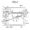
- Fig. 4 is a schematic plan view showing an elevator apparatus according to Embodiment 3 of the present invention.
- Fig. 5 is a front view showing a state in which the first car 8 of Fig. 4 and the first counterweight 10 of Fig. 4 are suspended.
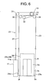
- Fig. 6 is a front view showing a state in which the second car 9 of Fig. 4 and the second counterweight 11 of Fig. 4 are suspended.
- the first counterweight 10 and the second counterweight 11 are disposed beside the first car 8 and the second car 9 so as to face the second lateral surfaces 8d and 9d when being located at the same height as the first car 8 and the second car 9, respectively. That is, the first counterweight 10 and the second counterweight 11 are disposed side by side in a width direction thereof.
- the first hoisting machine 12, the second hoisting machine 19, a first car-side deflector pulley 27, a first counterweight-side deflector pulley 28, a second car-side deflector pulley 29, a third car-side deflector pulley 30, a second counterweight-side deflector pulley 31, and a turning pulley 32 are disposed in the upper portion within the hoistway 1.
- the first hoisting machine 12 and the second hoisting machine 19 are disposed above the cars 8 and 9 so as to be located as a whole within the regions of the cars 8 and 9 on the vertical projection plane.
- the first car-side deflector pulley 27 is disposed above the cars 8 and 9 to lead the first suspension bodies 16 to the first car suspending portion 8e.
- the first counterweight-side deflector pulley 28 is disposed above the first counterweight 10 to lead the first suspension bodies 16 to the first counterweight suspending portion 10a.
- the second car-side deflector pulley 29 is disposed above the cars 8 and 9 to lead the second suspension body 23 to the second car suspending portion 9e.
- the third car-side deflector pulley 30 is disposed above the cars 8 and 9 to lead the third suspension body 24 to the third car suspending portion 9f.
- the second counterweight-side deflector pulley 31 is disposed above the second counterweight 11 to lead the second suspension body 23 and the third suspension body 24 to the second counterweight suspending portion 11a.
- the turning pulley 32 reverses the orientation of the second suspension body 23 drawn out from the second drive sheave 21, and leads the second suspension body 23 to the second car-side deflector pulley 29.
- the deflector pulleys 27 to 31 and the turning pulley 32 are disposed such that rotary shafts thereof extend horizontally.
- the hoisting machines 12 and 19, the deflector pulleys 27 and 31, and the turning pulley 32 are disposed so as to intersect with the same horizontal plane. That is, the hoisting machines 12 and 19, the deflector pulleys 27 to 31, and the turning pulley 32 are disposed so as to be located at least partially within the same height region.
- Embodiment 3 of the present invention is identical to Embodiment 1 of the present invention in other constructional details.
- the elevator apparatus constructed as described above also makes it possible to efficiently dispose the hoisting machines 12 and 19 and the groups of the pulleys in the upper portion of the hoistway 1 and hence achieve a reduction in installation space.
- the low-profile hoisting machine is illustrated as each of the first hoisting machine 12 and the second hoisting machine 19.
- a hoisting machine that is larger in dimension in an axial direction thereof than in a direction perpendicular to the axial direction may be employed instead.
- Fig. 7 is a schematic plan view showing an elevator apparatus according to Embodiment 4 of the present invention.
- Fig. 8 is a front view showing a state in which the first car 8 of Fig. 7 and the first counterweight 10 of Fig. 7 are suspended.
- Fig. 9 is a front view showing a state in which the second car 9 of Fig. 7 and the second counterweight 11 of Fig. 7 are suspended.
- the first hoisting machine 12 and the second hoisting machine 19 are disposed such that the rotary shafts of the drive sheaves 14 and 21 extend vertically. Accordingly, the turning pulley 32 is disposed such that the rotary shaft thereof extends substantially vertically, namely, slightly slantingly with respect to the vertical direction.
- Embodiment 4 of the present invention is identical to Embodiment 3 of the present invention in other constructional details.
- the elevator apparatus constructed as described above also makes it possible to efficiently dispose the hoisting machines 12 and 19 and the groups of the pulleys in the upper portion of the hoistway 1 and hence achieve a reduction in installation space.
- the two cars 8 and 9 are provided within the common hoistway 1. However, three or more cars may be provided therewithin.
- the second car suspending portion 9e and the third car suspending portion 9f are provided at the lower ends of the first lateral surface 9c and the second lateral surface 9d of the second car 9, respectively.
- the second car suspending portion 9e and the third car suspending portion 9f may be provided at upper ends or intermediate portions of the first lateral surface 9c and the second lateral surface 9d of the second car 9, respectively.
Landscapes
- Engineering & Computer Science (AREA)
- Structural Engineering (AREA)
- Civil Engineering (AREA)
- Mechanical Engineering (AREA)
- Automation & Control Theory (AREA)
- Lift-Guide Devices, And Elevator Ropes And Cables (AREA)
- Cage And Drive Apparatuses For Elevators (AREA)
Applications Claiming Priority (1)
| Application Number | Priority Date | Filing Date | Title |
|---|---|---|---|
| PCT/JP2006/309090 WO2007129385A1 (ja) | 2006-05-01 | 2006-05-01 | エレベータ装置 |
Publications (2)
| Publication Number | Publication Date |
|---|---|
| EP2014597A1 true EP2014597A1 (en) | 2009-01-14 |
| EP2014597A8 EP2014597A8 (en) | 2009-05-06 |
Family
ID=38667507
Family Applications (1)
| Application Number | Title | Priority Date | Filing Date |
|---|---|---|---|
| EP06745941A Withdrawn EP2014597A1 (en) | 2006-05-01 | 2006-05-01 | Elevator device |
Country Status (6)
| Country | Link |
|---|---|
| US (2) | US7918319B2 (ja) |
| EP (1) | EP2014597A1 (ja) |
| JP (1) | JPWO2007129385A1 (ja) |
| KR (1) | KR100961038B1 (ja) |
| CN (1) | CN101166686B (ja) |
| WO (1) | WO2007129385A1 (ja) |
Families Citing this family (12)
| Publication number | Priority date | Publication date | Assignee | Title |
|---|---|---|---|---|
| JPWO2007129385A1 (ja) * | 2006-05-01 | 2009-09-17 | 三菱電機株式会社 | エレベータ装置 |
| CN102264626B (zh) * | 2008-12-26 | 2014-02-19 | 因温特奥股份公司 | 电梯设备中的对重 |
| EP2424806A4 (en) * | 2009-04-29 | 2015-07-22 | Otis Elevator Co | LIFTING SYSTEM WITH SEVERAL CARS IN A SINGLE TRAVEL CHAIR |
| ES2543885T3 (es) * | 2009-12-15 | 2015-08-25 | Inventio Ag | Instalación de ascensor de doble cabina |
| EP2444352A1 (de) * | 2010-10-25 | 2012-04-25 | Inventio AG | Aufzuganlage |
| CN102815588B (zh) * | 2011-06-10 | 2015-05-13 | 铃木电梯(中国)有限公司 | 多功能电梯中的滑轮组及由此获得的多功能电梯 |
| ES2549795T3 (es) * | 2013-07-04 | 2015-11-02 | Kone Corporation | Un sistema de ascensor |
| CN105793184B (zh) * | 2013-12-09 | 2017-12-15 | 因温特奥股份公司 | 电梯设备 |
| EP3114067B1 (de) * | 2014-03-05 | 2018-04-04 | Inventio AG | Antrieb mit mehrfach-umschlingung für eine aufzusanlage |
| CN105800423A (zh) * | 2016-05-09 | 2016-07-27 | 江南嘉捷电梯股份有限公司 | 一种家用电梯 |
| KR101877955B1 (ko) * | 2017-08-09 | 2018-07-12 | 주식회사 송산특수엘리베이터 | 고하중용 초대형 엘리베이터의 견인 안정성 향상 및 로프 수명을 연장할 수 있는 로핑 방법 |
| JP7341094B2 (ja) * | 2020-03-25 | 2023-09-08 | 株式会社日立ビルシステム | 昇降路内作業装置及びその姿勢安定化方法 |
Family Cites Families (29)
| Publication number | Priority date | Publication date | Assignee | Title |
|---|---|---|---|---|
| JPS5155552A (ja) * | 1974-11-08 | 1976-05-15 | Hitachi Ltd | Erebeeta |
| JPS5722875A (en) | 1980-07-11 | 1982-02-05 | Matsushita Electric Ind Co Ltd | Arc welding apparatus |
| JPH07187525A (ja) * | 1993-11-18 | 1995-07-25 | Masami Sakita | 複数ばこエレベータシステム |
| JP4311590B2 (ja) * | 1999-06-14 | 2009-08-12 | 三菱電機株式会社 | エレベータ |
| DE60043310D1 (de) * | 2000-08-21 | 2009-12-24 | Mitsubishi Electric Corp | Aufzugseinrichtung |
| JPWO2002022487A1 (ja) * | 2000-09-14 | 2004-01-22 | 三菱電機株式会社 | エレベータ装置 |
| EP1329412B1 (en) * | 2000-10-10 | 2009-12-09 | Mitsubishi Denki Kabushiki Kaisha | Elevator device |
| JP4771586B2 (ja) * | 2000-12-08 | 2011-09-14 | 東芝エレベータ株式会社 | エレベータ |
| JP3527216B2 (ja) | 2001-05-29 | 2004-05-17 | シャープ株式会社 | 直流安定化電源回路 |
| JP3458848B2 (ja) | 2001-07-27 | 2003-10-20 | 三菱電機株式会社 | エレベータ装置 |
| JP2003104657A (ja) * | 2001-09-28 | 2003-04-09 | Toshiba Elevator Co Ltd | エレベータ |
| EP1481935A4 (en) * | 2002-03-01 | 2010-09-01 | Mitsubishi Electric Corp | ELEVATOR |
| JP4229633B2 (ja) * | 2002-04-26 | 2009-02-25 | 東芝エレベータ株式会社 | マシンルームレスエレベータ |
| JP2004001919A (ja) * | 2002-05-30 | 2004-01-08 | Otis Elevator Co | エレベータ装置 |
| JP2003146561A (ja) * | 2002-09-18 | 2003-05-21 | Toshiba Elevator Co Ltd | ダブルデッキエレベータ |
| JP4113760B2 (ja) * | 2002-11-01 | 2008-07-09 | 三菱電機株式会社 | エレベーター装置 |
| WO2004046009A1 (ja) * | 2002-11-18 | 2004-06-03 | Mitsubishi Denki Kabushiki Kaisha | エレベータ装置 |
| JP4401069B2 (ja) * | 2002-12-06 | 2010-01-20 | 東芝エレベータ株式会社 | マシンルームレスエレベータ |
| KR100728419B1 (ko) * | 2003-01-23 | 2007-06-13 | 미쓰비시덴키 가부시키가이샤 | 엘리베이터 장치 |
| CN100389056C (zh) * | 2003-03-06 | 2008-05-21 | 因温特奥股份公司 | 电梯 |
| FI116617B (fi) * | 2003-08-12 | 2006-01-13 | Kone Corp | Menetelmä ja laitteisto kaksoiskorihissin korivälin säätämiseksi |
| JPWO2005056455A1 (ja) * | 2003-12-09 | 2007-07-05 | 三菱電機株式会社 | エレベータ装置 |
| US7331424B2 (en) * | 2004-06-07 | 2008-02-19 | Mitsubishi Denki Kabushiki Kaisha | Elevator apparatus |
| WO2006006228A1 (ja) * | 2004-07-12 | 2006-01-19 | Mitsubishi Denki Kabushiki Kaisha | エレベータ装置 |
| JP2006036487A (ja) * | 2004-07-28 | 2006-02-09 | Toshiba Elevator Co Ltd | エレベータ装置 |
| JP4833225B2 (ja) * | 2004-12-29 | 2011-12-07 | オーチス エレベータ カンパニー | 1つの昇降路に複数のかごを有するエレベータシステムにおける補償 |
| EP2019072A1 (en) * | 2006-04-19 | 2009-01-28 | Mitsubishi Electric Corporation | Elevator device |
| JPWO2007129385A1 (ja) * | 2006-05-01 | 2009-09-17 | 三菱電機株式会社 | エレベータ装置 |
| US7661513B2 (en) * | 2006-12-14 | 2010-02-16 | Inventio Ag | Dual-car elevator system with common counterweight |
-
2006
- 2006-05-01 JP JP2007503736A patent/JPWO2007129385A1/ja active Pending
- 2006-05-01 WO PCT/JP2006/309090 patent/WO2007129385A1/ja active Application Filing
- 2006-05-01 KR KR1020077020893A patent/KR100961038B1/ko not_active IP Right Cessation
- 2006-05-01 EP EP06745941A patent/EP2014597A1/en not_active Withdrawn
- 2006-05-01 US US11/814,862 patent/US7918319B2/en not_active Expired - Fee Related
- 2006-05-01 CN CN2006800141906A patent/CN101166686B/zh not_active Expired - Fee Related
-
2011
- 2011-01-13 US US13/006,192 patent/US20110108366A1/en not_active Abandoned
Non-Patent Citations (1)
| Title |
|---|
| See references of WO2007129385A1 * |
Also Published As
| Publication number | Publication date |
|---|---|
| JPWO2007129385A1 (ja) | 2009-09-17 |
| KR20080003787A (ko) | 2008-01-08 |
| US7918319B2 (en) | 2011-04-05 |
| US20110108366A1 (en) | 2011-05-12 |
| US20090301818A1 (en) | 2009-12-10 |
| CN101166686A (zh) | 2008-04-23 |
| KR100961038B1 (ko) | 2010-06-01 |
| CN101166686B (zh) | 2010-09-08 |
| WO2007129385A1 (ja) | 2007-11-15 |
| EP2014597A8 (en) | 2009-05-06 |
Similar Documents
| Publication | Publication Date | Title |
|---|---|---|
| US7918319B2 (en) | Elevator apparatus | |
| JP5805212B2 (ja) | エレベータ装置 | |
| EP1471026A9 (en) | Elevator device | |
| EP1961688A1 (en) | Elevator device | |
| EP1481935A1 (en) | Elevaltor apparatus | |
| JP5460715B2 (ja) | エレベータ装置 | |
| EP1693328B1 (en) | Elevator apparatus | |
| EP2019072A1 (en) | Elevator device | |
| EP1754680A1 (en) | Elevator apparatus | |
| US8172041B2 (en) | Machine room-less elevator | |
| US7562745B2 (en) | Elevator with an operation space in a center of a machine room | |
| EP1564177B1 (en) | Elevator equipment | |
| WO2018198232A1 (ja) | エレベータ装置 | |
| EP2551228A1 (en) | Elevator apparatus | |
| EP2154099B1 (en) | Elevator device | |
| EP1795484B1 (en) | Elevator apparatus | |
| CN111465569A (zh) | 无机房电梯 | |
| EP1717184B1 (en) | Elevator | |
| EP1700813A1 (en) | Elevator system | |
| JP2008044744A (ja) | エレベータ装置 | |
| EP1930283A1 (en) | Elevator device | |
| EP1736431A1 (en) | Elevator apparatus | |
| JP2005231869A (ja) | エレベータ装置 |
Legal Events
| Date | Code | Title | Description |
|---|---|---|---|
| PUAI | Public reference made under article 153(3) epc to a published international application that has entered the european phase |
Free format text: ORIGINAL CODE: 0009012 |
|
| 17P | Request for examination filed |
Effective date: 20071106 |
|
| AK | Designated contracting states |
Kind code of ref document: A1 Designated state(s): AT BE BG CH CY CZ DE DK EE ES FI FR GB GR HU IE IS IT LI LT LU LV MC NL PL PT RO SE SI SK TR |
|
| AX | Request for extension of the european patent |
Extension state: AL BA HR MK YU |
|
| RAP1 | Party data changed (applicant data changed or rights of an application transferred) |
Owner name: MITSUBISHI ELECTRIC CORPORATION |
|
| RBV | Designated contracting states (corrected) |
Designated state(s): DE |
|
| DAX | Request for extension of the european patent (deleted) | ||
| STAA | Information on the status of an ep patent application or granted ep patent |
Free format text: STATUS: THE APPLICATION HAS BEEN WITHDRAWN |
|
| 18W | Application withdrawn |
Effective date: 20140205 |