EP2014472A2 - Flüssigabfallbehälter und Bilderzeugungsvorrichtung - Google Patents
Flüssigabfallbehälter und Bilderzeugungsvorrichtung Download PDFInfo
- Publication number
- EP2014472A2 EP2014472A2 EP08252330A EP08252330A EP2014472A2 EP 2014472 A2 EP2014472 A2 EP 2014472A2 EP 08252330 A EP08252330 A EP 08252330A EP 08252330 A EP08252330 A EP 08252330A EP 2014472 A2 EP2014472 A2 EP 2014472A2
- Authority
- EP
- European Patent Office
- Prior art keywords
- container
- waste liquid
- image forming
- sensor
- forming apparatus
- Prior art date
- Legal status (The legal status is an assumption and is not a legal conclusion. Google has not performed a legal analysis and makes no representation as to the accuracy of the status listed.)
- Granted
Links
- 239000002699 waste material Substances 0.000 title claims abstract description 232
- 239000007788 liquid Substances 0.000 title claims abstract description 215
- 238000007599 discharging Methods 0.000 claims description 21
- 238000001514 detection method Methods 0.000 claims description 13
- 230000015572 biosynthetic process Effects 0.000 claims description 8
- 230000008859 change Effects 0.000 claims description 4
- 239000000976 ink Substances 0.000 description 73
- 238000010586 diagram Methods 0.000 description 26
- 239000002910 solid waste Substances 0.000 description 14
- 238000004891 communication Methods 0.000 description 13
- 239000010808 liquid waste Substances 0.000 description 11
- 238000012423 maintenance Methods 0.000 description 11
- 230000007246 mechanism Effects 0.000 description 10
- 238000011084 recovery Methods 0.000 description 10
- 238000007639 printing Methods 0.000 description 8
- 230000003287 optical effect Effects 0.000 description 7
- 239000000463 material Substances 0.000 description 6
- 238000000034 method Methods 0.000 description 6
- 230000008569 process Effects 0.000 description 6
- 230000005684 electric field Effects 0.000 description 4
- 238000005086 pumping Methods 0.000 description 4
- 210000000078 claw Anatomy 0.000 description 3
- 230000006870 function Effects 0.000 description 3
- 239000000049 pigment Substances 0.000 description 3
- XEEYBQQBJWHFJM-UHFFFAOYSA-N Iron Chemical compound [Fe] XEEYBQQBJWHFJM-UHFFFAOYSA-N 0.000 description 2
- PXHVJJICTQNCMI-UHFFFAOYSA-N Nickel Chemical compound [Ni] PXHVJJICTQNCMI-UHFFFAOYSA-N 0.000 description 2
- 238000010521 absorption reaction Methods 0.000 description 2
- 238000009825 accumulation Methods 0.000 description 2
- 239000000853 adhesive Substances 0.000 description 2
- 239000003595 mist Substances 0.000 description 2
- 238000007789 sealing Methods 0.000 description 2
- RYGMFSIKBFXOCR-UHFFFAOYSA-N Copper Chemical compound [Cu] RYGMFSIKBFXOCR-UHFFFAOYSA-N 0.000 description 1
- 229910052782 aluminium Inorganic materials 0.000 description 1
- XAGFODPZIPBFFR-UHFFFAOYSA-N aluminium Chemical compound [Al] XAGFODPZIPBFFR-UHFFFAOYSA-N 0.000 description 1
- 239000000919 ceramic Substances 0.000 description 1
- 239000004020 conductor Substances 0.000 description 1
- 229910052802 copper Inorganic materials 0.000 description 1
- 239000010949 copper Substances 0.000 description 1
- 230000008020 evaporation Effects 0.000 description 1
- 238000001704 evaporation Methods 0.000 description 1
- 239000004744 fabric Substances 0.000 description 1
- 239000000835 fiber Substances 0.000 description 1
- 239000012530 fluid Substances 0.000 description 1
- 239000011521 glass Substances 0.000 description 1
- 238000010438 heat treatment Methods 0.000 description 1
- 229910052742 iron Inorganic materials 0.000 description 1
- 239000010985 leather Substances 0.000 description 1
- 230000014759 maintenance of location Effects 0.000 description 1
- 229910052751 metal Inorganic materials 0.000 description 1
- 239000002184 metal Substances 0.000 description 1
- 238000012986 modification Methods 0.000 description 1
- 230000004048 modification Effects 0.000 description 1
- 229910052759 nickel Inorganic materials 0.000 description 1
- 239000004033 plastic Substances 0.000 description 1
- 229920001296 polysiloxane Polymers 0.000 description 1
- 238000004064 recycling Methods 0.000 description 1
- 239000002904 solvent Substances 0.000 description 1
- 238000000638 solvent extraction Methods 0.000 description 1
- 239000010409 thin film Substances 0.000 description 1
- 239000002023 wood Substances 0.000 description 1
Images


Classifications
-
- B—PERFORMING OPERATIONS; TRANSPORTING
- B41—PRINTING; LINING MACHINES; TYPEWRITERS; STAMPS
- B41J—TYPEWRITERS; SELECTIVE PRINTING MECHANISMS, i.e. MECHANISMS PRINTING OTHERWISE THAN FROM A FORME; CORRECTION OF TYPOGRAPHICAL ERRORS
- B41J2/00—Typewriters or selective printing mechanisms characterised by the printing or marking process for which they are designed
- B41J2/005—Typewriters or selective printing mechanisms characterised by the printing or marking process for which they are designed characterised by bringing liquid or particles selectively into contact with a printing material
- B41J2/01—Ink jet
- B41J2/17—Ink jet characterised by ink handling
- B41J2/1721—Collecting waste ink; Collectors therefor
- B41J2/1728—Closed waste ink collectors
-
- B—PERFORMING OPERATIONS; TRANSPORTING
- B41—PRINTING; LINING MACHINES; TYPEWRITERS; STAMPS
- B41J—TYPEWRITERS; SELECTIVE PRINTING MECHANISMS, i.e. MECHANISMS PRINTING OTHERWISE THAN FROM A FORME; CORRECTION OF TYPOGRAPHICAL ERRORS
- B41J2/00—Typewriters or selective printing mechanisms characterised by the printing or marking process for which they are designed
- B41J2/005—Typewriters or selective printing mechanisms characterised by the printing or marking process for which they are designed characterised by bringing liquid or particles selectively into contact with a printing material
- B41J2/01—Ink jet
- B41J2/17—Ink jet characterised by ink handling
- B41J2/1721—Collecting waste ink; Collectors therefor
- B41J2/1742—Open waste ink collectors, e.g. ink receiving from a print head above the collector during borderless printing
Definitions
- image forming apparatuses there are printers, facsimile machines, copiers, and multi-function machines.
- image forming apparatuses there are printers, facsimile machines, copiers, and multi-function machines.
- a liquid jet recording apparatus (e.g., inkjet recording apparatus).
- the liquid jet recording apparatus performs an image forming (also referred to as “recording”, "printing” and the like) operation by using a recording head that ejects droplets of recording liquid (ink droplets) to a medium (e.g., paper, OHP sheet, also referred to as "recording medium”) onto which the ejected liquid droplets can adhere.
- Patent Document 2 discloses a waste liquid container for containing waste liquid by separately containing accumulated matter and liquid matter included in the waste liquid.
- This container is provided with a notch part and a space into which the waste liquid is introduced.
- the accumulated matter is contained in the space, and the liquid matter is absorbed by an absorbing member.
- Another embodiment of the present invention provides an image forming apparatus including an image forming part for performing image formation, a discharging part for discharging a waste liquid that does not contribute to image formation, and a waste liquid container for storing the waste liquid discharged from the discharging part, the waste liquid container including a first container having a single waste liquid inlet into which the waste liquid enters, and a second container communicating with the first container, wherein the first and the second containers are detachably attached to each other.
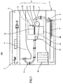
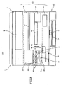
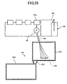
- a maintenance/recovery mechanism (maintenance/recovery apparatus) 38 is provided in a non-printing area on one end of the moving direction of the carriage 23 as shown in Figs. 2 and 3 .
- the recovery mechanism is for maintaining and recovering the condition of the nozzles 31 of the recording head 24.
- the recovery mechanism 38 includes a blank ejection receiver 39 for receiving droplets (droplets not used for recording) in a non-printing area on the other end of the moving direction of the carriage 23.
- a bottom part of the blank ejection receiver 43 is positioned facing the waste liquid container 40 for allowing unwanted waste liquid (ejected by blank-ejection) to be discharged (dropped) into the waste liquid container 40. Furthermore, four openings 39a are formed in the blank ejection receiver 39.
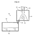
- waste liquid container 40 according to the above-described embodiments of the present invention is described in further detail with reference to Fig. 14 .
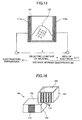
- waste ink (waste liquid not contributing to image formation) 121 discharged from the blank ejection receiver 43 or the discharge tube 46 is introduced into the waste liquid inlet 104, solid waste matter 122 contained in the waste ink 121 accumulates inside the first container 101 and liquid waste matter 123 contained in the waste ink 121 flows into the second container 102 via the communication path 103.
- plural first sensors 111 are provided on the entire sidewall of the first container 101 while plural second sensors 112 are also provided on the entire sidewall of the second container 102. With this configuration, the shape of the waste matter of the entire waste liquid container 40 can be detected.
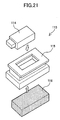
- the photosensor 114 has claw parts which pressingly engage the upper opening part of the case 115 when the photosensor 114 is inserted in the upper opening part of the case 115. Thereby, the photosensor 114 can be attached to the case 115.
- the absorbing member 116 is fixed to an absorbing member holding part of the case 115 by using, for example, an adhesive agent.
- the absorbing member 116 is attached to the top wall of the second container 102 in a manner that the absorbing member 116 faces the inside of the second container 102 and absorbs the waste ink inside the second container 102.
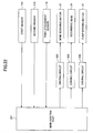
- the main control part 201 is for performing control of the entire image forming apparatus 100 including control for changing a waste liquid discharging position according to an embodiment of the present invention.
- the main control part 201 includes, for example, a CPU, a ROM, a RAM, an I/O device, and a rewritable non-volatile memory.
- the main control part 201 moves the carriage 23 in a desired direction for a prescribed amount by rotating the main scan motor 27 via a driving circuit 202.
- the main control part 201 drives the recording head 24 for ejecting liquid droplets (e.g., ink) via a driving circuit 203.
- the main control part 201 drives the absorbing pump 45 by rotating the absorbing pump motor 47 via a driving circuit 204.
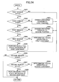
- One or more thresholds are set with respect to the shape (capacity) of the first container 101 of the waste liquid container 40 beforehand.
- the main control part 201 may control (limit) usage of the image forming apparatus 100 or change a position for discharging waste ink.
- thresholds D, E, F, G are set in correspondence with the height (position) of the solid waste matter 122 detected by the first sensor 111 (corresponding heights satisfying a relationship of D ⁇ E ⁇ F ⁇ G).
- the height of the solid waste matter 122 is equal to or greater than the threshold D (Yes in S501)
- the height H1 is less than the threshold E, that is, in a case where the height H1 is equal to or greater than the threshold D but less than the threshold E (D ⁇ H1 ⁇ E)
- the position for discharging waste ink into the first container 101 is changed to a predetermined first discharge position (variable position ⁇ ) (S601).
- the height H1 is equal to or greater than the threshold F
- the height H1 is less than the threshold G, that is, in a case where the height H1 is equal to or greater than the threshold F but less than the threshold G (F ⁇ H1 ⁇ G)
- a nearly-full container operation is performed.
- the nearly-full container operation includes, for example, a process for indicating that the first container 101 of the waste liquid container 40 is nearly full on a display of a control panel of the image forming apparatus 100 or reporting that the first container 101 of the waste liquid container 40 is nearly full to a printer driver of a host computer.
- the second container 102 is nearly full (nearly-full container).
- a nearly-full container operation is performed.
- the nearly-full container operation includes, for example, a process for indicating that the second container 102 of the waste liquid container 40 is nearly full on a display of a control panel of the image forming apparatus 100 or reporting that the second container 102 of the waste liquid container 40 is nearly full to a printer driver of a host computer.
- the height H2 is not less than the threshold C, that is, in a case where the height H2 is equal to or greater than the threshold C, it is determined that the second container 102 is full (full container).
- a full-container operation is performed.
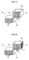
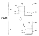
- Fig. 27 is a schematic diagram showing a detachable attachment structure of the sensor electrode 111a of the first sensor 111 according to an embodiment of the present invention.
- the waste liquid container 40 (including the first container 101 or the second container 102) is detachable from the main body 1 of the image forming apparatus 100 according to the above-described embodiment of the present invention, the waste liquid container 40 can be re-attached after eliminating stored waste liquid or replaced with a new waste liquid container. This facilitates maintenance of the image forming apparatus 100. Furthermore, since the presence of the waste liquid container 40 can be detected, waste liquid can be prevented from being erroneously discharged in a state where the waste liquid container 40 is not attached to the image forming apparatus 100. Accordingly, the surrounding of the waste liquid container 40 can be prevented from being stained by waste liquid.
Landscapes
- Ink Jet (AREA)
Applications Claiming Priority (1)
| Application Number | Priority Date | Filing Date | Title |
|---|---|---|---|
| JP2007184044A JP5151285B2 (ja) | 2007-07-13 | 2007-07-13 | 廃液収容容器及び画像形成装置 |
Publications (3)
| Publication Number | Publication Date |
|---|---|
| EP2014472A2 true EP2014472A2 (de) | 2009-01-14 |
| EP2014472A3 EP2014472A3 (de) | 2009-07-29 |
| EP2014472B1 EP2014472B1 (de) | 2011-09-14 |
Family
ID=39876237
Family Applications (1)
| Application Number | Title | Priority Date | Filing Date |
|---|---|---|---|
| EP08252330A Not-in-force EP2014472B1 (de) | 2007-07-13 | 2008-07-08 | Flüssigabfallbehälter und Bilderzeugungsvorrichtung |
Country Status (3)
| Country | Link |
|---|---|
| US (1) | US8899723B2 (de) |
| EP (1) | EP2014472B1 (de) |
| JP (1) | JP5151285B2 (de) |
Families Citing this family (15)
| Publication number | Priority date | Publication date | Assignee | Title |
|---|---|---|---|---|
| JP4985356B2 (ja) * | 2007-11-29 | 2012-07-25 | ブラザー工業株式会社 | 液体吐出装置 |
| US20100154706A1 (en) * | 2008-12-19 | 2010-06-24 | Canon Kabushiki Kaisha | Liquid applying apparatus |
| JP5824956B2 (ja) | 2011-08-16 | 2015-12-02 | 株式会社リコー | 画像形成装置 |
| JP5929199B2 (ja) | 2012-01-05 | 2016-06-01 | 株式会社リコー | 画像形成装置 |
| JP5927989B2 (ja) | 2012-02-29 | 2016-06-01 | 株式会社リコー | 画像形成装置 |
| JP5948993B2 (ja) * | 2012-03-14 | 2016-07-06 | セイコーエプソン株式会社 | 液体噴射装置 |
| KR102081249B1 (ko) * | 2013-05-27 | 2020-02-26 | 삼성디스플레이 주식회사 | 모니터링 장치 및 프린팅 장치 |
| US9555633B2 (en) | 2014-10-09 | 2017-01-31 | Ricoh Company, Ltd. | Replay unit for waste liquid container and image forming apparatus incorporating the relay unit |
| JP6707838B2 (ja) * | 2015-10-30 | 2020-06-10 | ブラザー工業株式会社 | 液体消費装置 |
| JP6790423B2 (ja) * | 2016-03-31 | 2020-11-25 | ブラザー工業株式会社 | インクジェット記録装置 |
| JP6852317B2 (ja) | 2016-09-09 | 2021-03-31 | ブラザー工業株式会社 | 液体回収装置、及びこれを備えた液体消費装置 |
| JP6425701B2 (ja) * | 2016-10-31 | 2018-11-21 | キヤノン株式会社 | インクジェット記録装置 |
| JP7139825B2 (ja) * | 2018-09-21 | 2022-09-21 | 株式会社リコー | 空吐出受け、液体を吐出する装置、印刷装置 |
| JP7280677B2 (ja) * | 2018-09-27 | 2023-05-24 | 株式会社日立産機システム | インクジェット記録装置 |
| JP2022026973A (ja) | 2020-07-31 | 2022-02-10 | 株式会社リコー | 液体吐出装置及び液体吐出方法 |
Citations (4)
| Publication number | Priority date | Publication date | Assignee | Title |
|---|---|---|---|---|
| JPH08267781A (ja) | 1995-03-31 | 1996-10-15 | Canon Inc | インクジェット記録装置 |
| JP2001310487A (ja) | 2000-04-28 | 2001-11-06 | Ricoh Co Ltd | 記録ヘッドの機能維持装置及びそれを使用したインクジェット記録装置 |
| JP2003011394A (ja) | 2001-07-04 | 2003-01-15 | Ricoh Co Ltd | インクジェット記録装置 |
| JP2007160871A (ja) | 2005-12-16 | 2007-06-28 | Canon Inc | インクジェット記録装置 |
Family Cites Families (16)
| Publication number | Priority date | Publication date | Assignee | Title |
|---|---|---|---|---|
| JPH08197749A (ja) * | 1995-01-31 | 1996-08-06 | Matsushita Electric Ind Co Ltd | インクジェットプリンタ装置 |
| JPH08290581A (ja) * | 1995-04-25 | 1996-11-05 | Matsushita Graphic Commun Syst Inc | インク供給装置およびこれを用いた記録装置 |
| US6312094B1 (en) * | 1997-07-30 | 2001-11-06 | Toshiba Tec Kabushiki Kaisha | Ink-jet printer |
| JP2000085143A (ja) | 1998-09-10 | 2000-03-28 | Copyer Co Ltd | 廃インク回収装置 |
| JP2000141704A (ja) | 1998-11-06 | 2000-05-23 | Fine Technol Kk | インクジェットプリンタの廃インク回収機構 |
| JP3818361B2 (ja) | 2000-10-20 | 2006-09-06 | セイコーエプソン株式会社 | 廃液トレイ及び該廃液トレイを備えたインクジェット式記録装置 |
| JP2004130701A (ja) * | 2002-10-11 | 2004-04-30 | Riso Kagaku Corp | インクジェット記録装置及びインクジェット記録装置の制御方法 |
| JP2004136550A (ja) | 2002-10-17 | 2004-05-13 | Seiko Epson Corp | インクジェット記録装置 |
| JP4570865B2 (ja) * | 2003-12-15 | 2010-10-27 | 株式会社リコー | ヘッドクリーニング装置及び画像形成装置 |
| JP2005247476A (ja) * | 2004-03-03 | 2005-09-15 | Ricoh Co Ltd | 画像形成装置 |
| JP2006007640A (ja) * | 2004-06-28 | 2006-01-12 | Seiko Epson Corp | 印刷装置、印刷方法、及び、印刷システム |
| JP2006137079A (ja) * | 2004-11-12 | 2006-06-01 | Ricoh Co Ltd | 廃液収容容器及び画像形成装置 |
| JP3933660B2 (ja) | 2004-12-03 | 2007-06-20 | 株式会社リコー | 画像形成装置 |
| JP2006281508A (ja) * | 2005-03-31 | 2006-10-19 | Canon Inc | インクジェット記録装置 |
| JP2007076308A (ja) * | 2005-09-16 | 2007-03-29 | Seiko Epson Corp | 廃液排出装置及び液体噴射装置 |
| JP2007125812A (ja) * | 2005-11-04 | 2007-05-24 | Canon Inc | インクジェット記録装置およびその回復方法 |
-
2007
- 2007-07-13 JP JP2007184044A patent/JP5151285B2/ja not_active Expired - Fee Related
-
2008
- 2008-07-08 EP EP08252330A patent/EP2014472B1/de not_active Not-in-force
- 2008-07-09 US US12/170,147 patent/US8899723B2/en not_active Expired - Fee Related
Patent Citations (4)
| Publication number | Priority date | Publication date | Assignee | Title |
|---|---|---|---|---|
| JPH08267781A (ja) | 1995-03-31 | 1996-10-15 | Canon Inc | インクジェット記録装置 |
| JP2001310487A (ja) | 2000-04-28 | 2001-11-06 | Ricoh Co Ltd | 記録ヘッドの機能維持装置及びそれを使用したインクジェット記録装置 |
| JP2003011394A (ja) | 2001-07-04 | 2003-01-15 | Ricoh Co Ltd | インクジェット記録装置 |
| JP2007160871A (ja) | 2005-12-16 | 2007-06-28 | Canon Inc | インクジェット記録装置 |
Also Published As
| Publication number | Publication date |
|---|---|
| JP2009018529A (ja) | 2009-01-29 |
| EP2014472A3 (de) | 2009-07-29 |
| US20090015632A1 (en) | 2009-01-15 |
| US8899723B2 (en) | 2014-12-02 |
| JP5151285B2 (ja) | 2013-02-27 |
| EP2014472B1 (de) | 2011-09-14 |
Similar Documents
| Publication | Publication Date | Title |
|---|---|---|
| EP2014472B1 (de) | Flüssigabfallbehälter und Bilderzeugungsvorrichtung | |
| US8770689B2 (en) | Image forming apparatus including recording head for ejecting droplets | |
| US20090021548A1 (en) | Inkjet printing apparatus and method for performing maintenance on inkjet printing apparatus | |
| EP2651648B1 (de) | Bilderzeugungsvorrichtung | |
| US8870317B2 (en) | Image forming apparatus including recording head and head tank | |
| US8894169B2 (en) | Image forming apparatus including recording head for ejecting liquid droplets | |
| KR100879145B1 (ko) | 화상 형성 장치 | |
| US8628168B2 (en) | Image forming apparatus and image forming method | |
| US6296354B1 (en) | Ink container with plural ink chambers emptied sequentially, and recording apparatus having the same | |
| JP3577010B2 (ja) | インクの残量検出方法およびインクジェット記録装置 | |
| US8777370B2 (en) | Image forming apparatus | |
| JP3933660B2 (ja) | 画像形成装置 | |
| US8727494B2 (en) | Droplet ejection device and image forming apparatus | |
| JP2008302501A (ja) | 廃液収容容器、画像形成装置 | |
| US8672446B2 (en) | Image forming apparatus including recording head for ejecting liquid droplets | |
| KR20130038928A (ko) | 화상 형성 장치 | |
| JP4860516B2 (ja) | 廃液収容容器及び画像形成装置 | |
| JP4410023B2 (ja) | インク袋、インクカートリッジ、インクジェット記録装置、及び画像形成装置 | |
| JP4919651B2 (ja) | 画像形成装置 | |
| JP2007098777A (ja) | 画像形成装置 | |
| JP4909186B2 (ja) | 画像形成装置および画像形成方法 | |
| JP2010005843A (ja) | 画像形成装置及び液体収容容器 | |
| JP2006137079A (ja) | 廃液収容容器及び画像形成装置 | |
| JP4993574B2 (ja) | 画像形成装置、交換用廃液タンク、廃液タンク | |
| JP2006150872A (ja) | 廃液収容容器及び画像形成装置 |
Legal Events
| Date | Code | Title | Description |
|---|---|---|---|
| PUAI | Public reference made under article 153(3) epc to a published international application that has entered the european phase |
Free format text: ORIGINAL CODE: 0009012 |
|
| 17P | Request for examination filed |
Effective date: 20080708 |
|
| AK | Designated contracting states |
Kind code of ref document: A2 Designated state(s): AT BE BG CH CY CZ DE DK EE ES FI FR GB GR HR HU IE IS IT LI LT LU LV MC MT NL NO PL PT RO SE SI SK TR |
|
| AX | Request for extension of the european patent |
Extension state: AL BA MK RS |
|
| PUAL | Search report despatched |
Free format text: ORIGINAL CODE: 0009013 |
|
| AK | Designated contracting states |
Kind code of ref document: A3 Designated state(s): AT BE BG CH CY CZ DE DK EE ES FI FR GB GR HR HU IE IS IT LI LT LU LV MC MT NL NO PL PT RO SE SI SK TR |
|
| AX | Request for extension of the european patent |
Extension state: AL BA MK RS |
|
| AKX | Designation fees paid |
Designated state(s): DE ES FR GB IT |
|
| 17Q | First examination report despatched |
Effective date: 20100531 |
|
| GRAP | Despatch of communication of intention to grant a patent |
Free format text: ORIGINAL CODE: EPIDOSNIGR1 |
|
| GRAS | Grant fee paid |
Free format text: ORIGINAL CODE: EPIDOSNIGR3 |
|
| GRAA | (expected) grant |
Free format text: ORIGINAL CODE: 0009210 |
|
| AK | Designated contracting states |
Kind code of ref document: B1 Designated state(s): DE ES FR GB IT |
|
| REG | Reference to a national code |
Ref country code: GB Ref legal event code: FG4D |
|
| REG | Reference to a national code |
Ref country code: DE Ref legal event code: R096 Ref document number: 602008009760 Country of ref document: DE Effective date: 20111110 |
|
| PG25 | Lapsed in a contracting state [announced via postgrant information from national office to epo] |
Ref country code: IT Free format text: LAPSE BECAUSE OF FAILURE TO SUBMIT A TRANSLATION OF THE DESCRIPTION OR TO PAY THE FEE WITHIN THE PRESCRIBED TIME-LIMIT Effective date: 20110914 |
|
| PLBE | No opposition filed within time limit |
Free format text: ORIGINAL CODE: 0009261 |
|
| STAA | Information on the status of an ep patent application or granted ep patent |
Free format text: STATUS: NO OPPOSITION FILED WITHIN TIME LIMIT |
|
| 26N | No opposition filed |
Effective date: 20120615 |
|
| REG | Reference to a national code |
Ref country code: DE Ref legal event code: R097 Ref document number: 602008009760 Country of ref document: DE Effective date: 20120615 |
|
| PG25 | Lapsed in a contracting state [announced via postgrant information from national office to epo] |
Ref country code: ES Free format text: LAPSE BECAUSE OF FAILURE TO SUBMIT A TRANSLATION OF THE DESCRIPTION OR TO PAY THE FEE WITHIN THE PRESCRIBED TIME-LIMIT Effective date: 20111225 |
|
| REG | Reference to a national code |
Ref country code: FR Ref legal event code: PLFP Year of fee payment: 9 |
|
| PGFP | Annual fee paid to national office [announced via postgrant information from national office to epo] |
Ref country code: DE Payment date: 20160722 Year of fee payment: 9 Ref country code: GB Payment date: 20160721 Year of fee payment: 9 |
|
| PGFP | Annual fee paid to national office [announced via postgrant information from national office to epo] |
Ref country code: FR Payment date: 20160721 Year of fee payment: 9 |
|
| REG | Reference to a national code |
Ref country code: DE Ref legal event code: R119 Ref document number: 602008009760 Country of ref document: DE |
|
| GBPC | Gb: european patent ceased through non-payment of renewal fee |
Effective date: 20170708 |
|
| REG | Reference to a national code |
Ref country code: FR Ref legal event code: ST Effective date: 20180330 |
|
| PG25 | Lapsed in a contracting state [announced via postgrant information from national office to epo] |
Ref country code: DE Free format text: LAPSE BECAUSE OF NON-PAYMENT OF DUE FEES Effective date: 20180201 Ref country code: GB Free format text: LAPSE BECAUSE OF NON-PAYMENT OF DUE FEES Effective date: 20170708 |
|
| PG25 | Lapsed in a contracting state [announced via postgrant information from national office to epo] |
Ref country code: FR Free format text: LAPSE BECAUSE OF NON-PAYMENT OF DUE FEES Effective date: 20170731 |