EP2010774B1 - Vanne a deux papillons actionnes par un moteur commun - Google Patents
Vanne a deux papillons actionnes par un moteur commun Download PDFInfo
- Publication number
- EP2010774B1 EP2010774B1 EP20070731373 EP07731373A EP2010774B1 EP 2010774 B1 EP2010774 B1 EP 2010774B1 EP 20070731373 EP20070731373 EP 20070731373 EP 07731373 A EP07731373 A EP 07731373A EP 2010774 B1 EP2010774 B1 EP 2010774B1
- Authority
- EP
- European Patent Office
- Prior art keywords
- butterfly
- transmission wheel
- closed position
- duct
- valve according
- Prior art date
- Legal status (The legal status is an assumption and is not a legal conclusion. Google has not performed a legal analysis and makes no representation as to the accuracy of the status listed.)
- Active
Links
- 230000009977 dual effect Effects 0.000 title 1
- 230000005540 biological transmission Effects 0.000 claims description 59
- 241000255777 Lepidoptera Species 0.000 claims description 14
- 238000010438 heat treatment Methods 0.000 claims description 2
- 241000510032 Ellipsaria lineolata Species 0.000 description 43
- 235000001954 papillon Nutrition 0.000 description 16
- 244000229285 papillon Species 0.000 description 14
- 230000015572 biosynthetic process Effects 0.000 description 2
- 239000012530 fluid Substances 0.000 description 2
- 239000007789 gas Substances 0.000 description 2
- XAGFODPZIPBFFR-UHFFFAOYSA-N aluminium Chemical compound [Al] XAGFODPZIPBFFR-UHFFFAOYSA-N 0.000 description 1
- 229910052782 aluminium Inorganic materials 0.000 description 1
- 230000000903 blocking effect Effects 0.000 description 1
- 238000001816 cooling Methods 0.000 description 1
- 230000004907 flux Effects 0.000 description 1
- 238000012423 maintenance Methods 0.000 description 1
Images


Classifications
-
- F—MECHANICAL ENGINEERING; LIGHTING; HEATING; WEAPONS; BLASTING
- F02—COMBUSTION ENGINES; HOT-GAS OR COMBUSTION-PRODUCT ENGINE PLANTS
- F02B—INTERNAL-COMBUSTION PISTON ENGINES; COMBUSTION ENGINES IN GENERAL
- F02B29/00—Engines characterised by provision for charging or scavenging not provided for in groups F02B25/00, F02B27/00 or F02B33/00 - F02B39/00; Details thereof
- F02B29/04—Cooling of air intake supply
- F02B29/0406—Layout of the intake air cooling or coolant circuit
- F02B29/0418—Layout of the intake air cooling or coolant circuit the intake air cooler having a bypass or multiple flow paths within the heat exchanger to vary the effective heat transfer surface
-
- F—MECHANICAL ENGINEERING; LIGHTING; HEATING; WEAPONS; BLASTING
- F16—ENGINEERING ELEMENTS AND UNITS; GENERAL MEASURES FOR PRODUCING AND MAINTAINING EFFECTIVE FUNCTIONING OF MACHINES OR INSTALLATIONS; THERMAL INSULATION IN GENERAL
- F16K—VALVES; TAPS; COCKS; ACTUATING-FLOATS; DEVICES FOR VENTING OR AERATING
- F16K1/00—Lift valves or globe valves, i.e. cut-off apparatus with closure members having at least a component of their opening and closing motion perpendicular to the closing faces
- F16K1/16—Lift valves or globe valves, i.e. cut-off apparatus with closure members having at least a component of their opening and closing motion perpendicular to the closing faces with pivoted closure-members
- F16K1/18—Lift valves or globe valves, i.e. cut-off apparatus with closure members having at least a component of their opening and closing motion perpendicular to the closing faces with pivoted closure-members with pivoted discs or flaps
- F16K1/22—Lift valves or globe valves, i.e. cut-off apparatus with closure members having at least a component of their opening and closing motion perpendicular to the closing faces with pivoted closure-members with pivoted discs or flaps with axis of rotation crossing the valve member, e.g. butterfly valves
- F16K1/221—Lift valves or globe valves, i.e. cut-off apparatus with closure members having at least a component of their opening and closing motion perpendicular to the closing faces with pivoted closure-members with pivoted discs or flaps with axis of rotation crossing the valve member, e.g. butterfly valves specially adapted operating means therefor
-
- F—MECHANICAL ENGINEERING; LIGHTING; HEATING; WEAPONS; BLASTING
- F16—ENGINEERING ELEMENTS AND UNITS; GENERAL MEASURES FOR PRODUCING AND MAINTAINING EFFECTIVE FUNCTIONING OF MACHINES OR INSTALLATIONS; THERMAL INSULATION IN GENERAL
- F16K—VALVES; TAPS; COCKS; ACTUATING-FLOATS; DEVICES FOR VENTING OR AERATING
- F16K31/00—Actuating devices; Operating means; Releasing devices
- F16K31/44—Mechanical actuating means
- F16K31/53—Mechanical actuating means with toothed gearing
-
- F—MECHANICAL ENGINEERING; LIGHTING; HEATING; WEAPONS; BLASTING
- F16—ENGINEERING ELEMENTS AND UNITS; GENERAL MEASURES FOR PRODUCING AND MAINTAINING EFFECTIVE FUNCTIONING OF MACHINES OR INSTALLATIONS; THERMAL INSULATION IN GENERAL
- F16K—VALVES; TAPS; COCKS; ACTUATING-FLOATS; DEVICES FOR VENTING OR AERATING
- F16K35/00—Means to prevent accidental or unauthorised actuation
- F16K35/14—Means to prevent accidental or unauthorised actuation interlocking two or more valves
-
- F—MECHANICAL ENGINEERING; LIGHTING; HEATING; WEAPONS; BLASTING
- F02—COMBUSTION ENGINES; HOT-GAS OR COMBUSTION-PRODUCT ENGINE PLANTS
- F02D—CONTROLLING COMBUSTION ENGINES
- F02D9/00—Controlling engines by throttling air or fuel-and-air induction conduits or exhaust conduits
- F02D9/02—Controlling engines by throttling air or fuel-and-air induction conduits or exhaust conduits concerning induction conduits
- F02D2009/0201—Arrangements; Control features; Details thereof
- F02D2009/0279—Throttle valve control for intake system with two parallel air flow paths, each controlled by a throttle, e.g. a resilient flap disposed on a throttle
-
- Y—GENERAL TAGGING OF NEW TECHNOLOGICAL DEVELOPMENTS; GENERAL TAGGING OF CROSS-SECTIONAL TECHNOLOGIES SPANNING OVER SEVERAL SECTIONS OF THE IPC; TECHNICAL SUBJECTS COVERED BY FORMER USPC CROSS-REFERENCE ART COLLECTIONS [XRACs] AND DIGESTS
- Y02—TECHNOLOGIES OR APPLICATIONS FOR MITIGATION OR ADAPTATION AGAINST CLIMATE CHANGE
- Y02T—CLIMATE CHANGE MITIGATION TECHNOLOGIES RELATED TO TRANSPORTATION
- Y02T10/00—Road transport of goods or passengers
- Y02T10/10—Internal combustion engine [ICE] based vehicles
- Y02T10/12—Improving ICE efficiencies
-
- Y—GENERAL TAGGING OF NEW TECHNOLOGICAL DEVELOPMENTS; GENERAL TAGGING OF CROSS-SECTIONAL TECHNOLOGIES SPANNING OVER SEVERAL SECTIONS OF THE IPC; TECHNICAL SUBJECTS COVERED BY FORMER USPC CROSS-REFERENCE ART COLLECTIONS [XRACs] AND DIGESTS
- Y10—TECHNICAL SUBJECTS COVERED BY FORMER USPC
- Y10T—TECHNICAL SUBJECTS COVERED BY FORMER US CLASSIFICATION
- Y10T137/00—Fluid handling
- Y10T137/8593—Systems
- Y10T137/86493—Multi-way valve unit
- Y10T137/86847—Pivoted valve unit
-
- Y—GENERAL TAGGING OF NEW TECHNOLOGICAL DEVELOPMENTS; GENERAL TAGGING OF CROSS-SECTIONAL TECHNOLOGIES SPANNING OVER SEVERAL SECTIONS OF THE IPC; TECHNICAL SUBJECTS COVERED BY FORMER USPC CROSS-REFERENCE ART COLLECTIONS [XRACs] AND DIGESTS
- Y10—TECHNICAL SUBJECTS COVERED BY FORMER USPC
- Y10T—TECHNICAL SUBJECTS COVERED BY FORMER US CLASSIFICATION
- Y10T137/00—Fluid handling
- Y10T137/8593—Systems
- Y10T137/86493—Multi-way valve unit
- Y10T137/86863—Rotary valve unit
-
- Y—GENERAL TAGGING OF NEW TECHNOLOGICAL DEVELOPMENTS; GENERAL TAGGING OF CROSS-SECTIONAL TECHNOLOGIES SPANNING OVER SEVERAL SECTIONS OF THE IPC; TECHNICAL SUBJECTS COVERED BY FORMER USPC CROSS-REFERENCE ART COLLECTIONS [XRACs] AND DIGESTS
- Y10—TECHNICAL SUBJECTS COVERED BY FORMER USPC
- Y10T—TECHNICAL SUBJECTS COVERED BY FORMER US CLASSIFICATION
- Y10T137/00—Fluid handling
- Y10T137/8593—Systems
- Y10T137/86928—Sequentially progressive opening or closing of plural valves
- Y10T137/87016—Lost motion
-
- Y—GENERAL TAGGING OF NEW TECHNOLOGICAL DEVELOPMENTS; GENERAL TAGGING OF CROSS-SECTIONAL TECHNOLOGIES SPANNING OVER SEVERAL SECTIONS OF THE IPC; TECHNICAL SUBJECTS COVERED BY FORMER USPC CROSS-REFERENCE ART COLLECTIONS [XRACs] AND DIGESTS
- Y10—TECHNICAL SUBJECTS COVERED BY FORMER USPC
- Y10T—TECHNICAL SUBJECTS COVERED BY FORMER US CLASSIFICATION
- Y10T137/00—Fluid handling
- Y10T137/8593—Systems
- Y10T137/87096—Valves with separate, correlated, actuators
- Y10T137/87113—Interlocked
-
- Y—GENERAL TAGGING OF NEW TECHNOLOGICAL DEVELOPMENTS; GENERAL TAGGING OF CROSS-SECTIONAL TECHNOLOGIES SPANNING OVER SEVERAL SECTIONS OF THE IPC; TECHNICAL SUBJECTS COVERED BY FORMER USPC CROSS-REFERENCE ART COLLECTIONS [XRACs] AND DIGESTS
- Y10—TECHNICAL SUBJECTS COVERED BY FORMER USPC
- Y10T—TECHNICAL SUBJECTS COVERED BY FORMER US CLASSIFICATION
- Y10T137/00—Fluid handling
- Y10T137/8593—Systems
- Y10T137/87265—Dividing into parallel flow paths with recombining
- Y10T137/8741—With common operator
- Y10T137/87442—Rotary valve
- Y10T137/87467—Axes of rotation parallel
- Y10T137/87483—Adjacent plate valves counter rotate
-
- Y—GENERAL TAGGING OF NEW TECHNOLOGICAL DEVELOPMENTS; GENERAL TAGGING OF CROSS-SECTIONAL TECHNOLOGIES SPANNING OVER SEVERAL SECTIONS OF THE IPC; TECHNICAL SUBJECTS COVERED BY FORMER USPC CROSS-REFERENCE ART COLLECTIONS [XRACs] AND DIGESTS
- Y10—TECHNICAL SUBJECTS COVERED BY FORMER USPC
- Y10T—TECHNICAL SUBJECTS COVERED BY FORMER US CLASSIFICATION
- Y10T137/00—Fluid handling
- Y10T137/8593—Systems
- Y10T137/877—With flow control means for branched passages
- Y10T137/87708—With common valve operator
- Y10T137/87732—With gearing
-
- Y—GENERAL TAGGING OF NEW TECHNOLOGICAL DEVELOPMENTS; GENERAL TAGGING OF CROSS-SECTIONAL TECHNOLOGIES SPANNING OVER SEVERAL SECTIONS OF THE IPC; TECHNICAL SUBJECTS COVERED BY FORMER USPC CROSS-REFERENCE ART COLLECTIONS [XRACs] AND DIGESTS
- Y10—TECHNICAL SUBJECTS COVERED BY FORMER USPC
- Y10T—TECHNICAL SUBJECTS COVERED BY FORMER US CLASSIFICATION
- Y10T137/00—Fluid handling
- Y10T137/8593—Systems
- Y10T137/877—With flow control means for branched passages
- Y10T137/87708—With common valve operator
- Y10T137/87772—With electrical actuation
Definitions
- the present invention relates to a valve intended for example to be implanted in an air intake circuit of a heat engine.
- Such a valve is known from the document EP-A-0 388 505 .
- Such an intake circuit comprises a cooled track and an uncooled track which are connected to the intake manifold of the engine by valves.
- valves In the context of the invention, it has been imagined to replace these valves by a single valve comprising a body delimiting a first conduit and a second conduit which are respectively connected to the uncooled path and the cooled path and which open into a third conduit. connected to the intake manifold.
- the first conduit and the second conduit are provided with a first butterfly and a second butterfly each having an open position and a closed position.
- the first throttle must be able to be held in position between the open position and the closed position in order to allow adjustment of the throttle that it provides while the second throttle must be movable either in its open position or in its closed position without an intermediate position being necessary.
- the valve thus has a normal operating state in which the first throttle is set in position between its open position and its closed position while the second throttle is closed, a blocking state in which the first throttle and the second throttle are in the closed position, and a cooling state in which the first throttle is in the closed position and the second throttle is in the open position.
- actuation of the butterflies made by means of two torque motors each associated with one of the butterflies. The use of two torque motors, however, would make the valve complex, cumbersome and relatively expensive.
- An object of the invention is to provide a butterfly control means that is simple and economical.
- a valve comprising a body delimiting first and second ducts which open into a third duct and which are provided respectively with a first butterfly and a second butterfly.
- the first butterfly is secured to a first transmission wheel connected to an output shaft of an actuating motor to be movable between a first closed position and a second closed position located on either side of a opening position of the first conduit.
- the second throttle valve is mounted to pivot on a second transmission wheel connected to the actuating motor, and is connected to the second transmission wheel by a positive one-way drive element when the first throttle is moved from its open position to its second closed position to then cause the second throttle valve from a closed position to an open position of the second conduit, the valve having a second throttle return member to its closed position when the first throttle is moved towards its first closed position.
- the first butterfly can be set in position between its open position and its first position closure without the second butterfly leaves its closed position in which it is held by the return member.
- the unidirectional drive element causes the second throttle to move to its open position.
- the actuating motor thus drives the first transmission wheel, and therefore the first throttle, and the second transmission wheel, the second throttle not being secured in rotation by the driving element in only one direction of rotation. rotation.
- the actuating motor is a DC motor.
- Such a motor has a torque greater than the torque developed by a torque motor.
- the second lug is secured to an axis having an end projecting from the body and provided with a radial support to cooperate with an abutment integral with the second transmission wheel and, preferably, the radial support. is equipped with a finger parallel to the axis and slidably received in an arcuate groove which is formed on the second transmission wheel and one end of which forms the drive abutment.
- the drive member thus has a simple structure.
- the second transmission wheel is connected to the actuating motor by the first transmission wheel.
- the first transmission wheel is a simple means of transmitting the movement of the output shaft of the actuating motor to the second transmission wheel.
- the second butterfly is secured to an axis having an end projecting from the body and provided with a solidarity support in rotation of the axis
- the second transmission wheel is mounted free to rotate on this end of the axis and is connected to the support by a torsion spring forming the return member and positioned to return the support to the position of closing of the second butterfly.
- a single spring can thus ensure the return of the two flaps in the closed position.
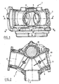
- the valve according to the invention comprises a body generally designated at 1 delimiting a first duct 3 and a second duct 4 opening into a third duct 2.
- the body 1 and the ducts 3 and 4 are represented only partly on the Figures 5 to 7 .
- the first duct 3 is equipped with a first butterfly 5 secured to an axis 6 mounted to pivot on the body 1.
- the shaft 6 comprises an end projecting from the body 1 and integral in rotation with a first wheel transmission 7, toothed, engaged with an intermediate gear 8 itself engaged with a pinion 9 integral with an output shaft of a motor 10 mounted on the body 1.
- the motor 10 is a DC motor known in itself connected to a source of electrical energy and a control module which are also known in themselves and are not shown in the figures.
- a torsion spring 11 extends helically around said end of the axis 6 having one end connected to the transmission wheel 7 and one end connected to the body 1. The spring 11 recalls the butterfly 5 in the open position ( represented on the Figures 2 to 4 ).
- the transmission wheel 7 is provided with lugs 12, 13 which are intended to cooperate with a stop 14 integral with the body 1.
- the butterfly 5 When the lug 12 is in abutment against the stop 14, the butterfly 5 is in a first closed position (represented on the figure 6 ) and when ergot 13 is in abutment against the stop 14, the butterfly 5 is in a second closed position (shown in FIG. figure 7 ).
- the butterfly 5 is substantially perpendicular to the duct 3 when it is in its first closed position and in its second closed position, these positions being at about 180 ° to one another.
- Resistors, schematized at 29, extend in the conduit 3 downstream of the butterfly 5 and are fixed to the body 1.
- the resistors 29 pass the fluid and are in the form of aluminum fins or thin resistive ribbons whose thickness and shapes are arranged not to hinder or disrupt the flow of the fluid. Resistors 29 comprise means, known in themselves and not shown, for connection to a source of electrical power supply.
- the second duct 4 is equipped with a second butterfly 15 secured to an axle 16 which is mounted to pivot on the body 1 and which has an end projecting from the body 1 and on which is mounted to pivot a second wheel 17.
- a support is fixed on this end of the axis 16.
- the support defines two arms 18, 19, extending radially from the projecting end of the axis 6, the opposite one of the other.
- Each arm 18, 19 is provided with a finger 20, 21 received in a groove 22, 23, in an arc formed in the transmission wheel 17.
- the arm 19 has a free end intended to abut against a stop 24 integral with the body 1 and defining the closed position of the throttle valve 15 (shown in FIGS. Figures 2 to 6 ).
- a torsion spring 25 extends helically around said end of the shaft 16 and has one end connected to the finger 21 and an opposite end connected to the body 1 to bias the butterfly 15 in the closed position. In the open position, the butterfly 15 extends substantially along the axis of the duct 4.
- the abutments 14, 24 are fixed on an adjustable support in position relative to the body 1.
- the engine 10 is to bring the throttle valve 5 into any position between its open position and its first closed position (see the intermediate position shown in FIG. figure 5 ).
- the butterfly 5 When the butterfly 5 is in the open position ( figure 3 ), the fingers 20, 21 are received in one end 22.1, 23.1 of the grooves 22, 23.
- the transmission wheel 7 pivots between the open position of the butterfly valve 5 and its first closed position, the transmission wheel 7 drives the transmission wheel 17 (direction of rotation 40 on the figure 3 ) by causing the fingers to slide along the grooves 22, 23 towards the other end 22.2, 23.2 of these grooves.
- the butterfly 15 is thus immobile, kept in its closed position by the spring applying the protrusion of the arm 18 against the abutment 24.
- the transmission wheel 7 When the transmission wheel 7 is moved to bring the butterfly valve 5 into its second closed position, the transmission wheel 7 causes the transmission wheel 17 to rotate in the direction referenced 30 on the figure 3 .
- the fingers 19, 20 being in abutment against the ends 22.1, 23.1 of the grooves 22, 23, the pivoting of the transmission wheel 17 will cause a pivoting of the support and therefore of the axis 16 and the butterfly 15.
- the butterfly 15 When the butterfly 5 reached its second closed position, the butterfly 15 is in its open position.
- the valve is in its secondary operating mode ( figure 7 ).
- the fingers 20, 21 and the grooves 22, 23 thus form a unidirectional drive member (direction 30) of the throttle valve 15, this member being positive (or active) when the throttle valve 5 is driven from its open position to its second position. closing position.
- a support 50 is fixed on the end of the axis 16 on which the transmission wheel 17 is mounted to pivot.
- the support 50 comprises an arm 51 intended to abut against a stop 24 integral with the body 1 and defining the closed position of the throttle valve 15 ( Figures 8 and 9 ).
- the transmission wheel 17 has a bearing portion against the arm 51.
- the torsion spring 25 extends helically around said end of the axis 16 and has one end connected to the support 50 and an opposite end connected to the transmission wheel 17 so as to apply the arm 51 against the transmission wheel 17 and remember the arm 51 towards the stop 24.
- the transmission wheel 17 abuts against the arm 51 of the support 56 when the transmission wheel 7 is moved to bring the butterfly valve 5 into its open position towards its second closed position and correspondingly drives the transmission wheel 17
- the transmission wheel 17 then moves the flap 15 from its closed position to its open position via the support 50 (FIG. figure 10 ).
- the transmission wheel 17 pivots in the opposite direction to return the butterfly valve 5 to its open position, the transmission wheel 17 is brought into abutment against the arm 51 and the torsion spring 25 recalls the support 50 against the abutment 24 ( figure 11 ).
- the arm 51 In the open position of the throttle valve 5, the arm 51 is in abutment against the stop 24 and the transmission wheel 15 is in abutment against the arm 51.
- the torsion spring 25 tends to press the arm 51 against the stop 24 and to pivot the transmission wheel 17 to bring it into contact with the arm 51 so that the butterfly 5 is in the open position and the butterfly 16 is in the closed position ( figure 11 ).
- valve may have a structure different from that described, in particular as regards the arrangement of the conduits, the geometry of the butterflies, the driving of the second transmission wheel, etc.
- the transmission wheels may be driven at means of belts.
- the motor can be engaged with the first transmission wheel and with the second transmission wheel, the first transmission wheel no longer serving as a link between the engine and the second transmission wheel.
- the body can be in one or more rooms.
- the second throttle return member may be a mechanical or electrical motor member.
- the unidirectional drive member may have another structure than that described and include for example only a finger and a groove.
- a finger can also be secured to the transmission wheel 17 to bear on the arm 19.
- the arrangement in which at least one of the butterflies 5, 15 in the open position has a projecting portion in the third duct 2, and at least one of the butterflies 5, 15 in the closed position extends substantially adjacent or even flush with the third conduit 2, is applicable to any type of valve having three ducts, for example an inlet and two outlets, with two butterflies controlled by one or two motors.
- the resistors 29 can be used in any type of valve having three ducts, in particular an inlet and two outlets.
- the heating means can be provided in one and / or the other of the ducts and have a different structure from that described.
- the return direction of the springs and the return position of the butterflies may be different from those described above.
- the valve can have many applications in particular in the automotive field and more particularly, but not exclusively, in the intake circuit of a heat engine.
Description
- La présente invention concerne une vanne destinée par exemple à être implantée dans un circuit d'admission d'air d'un moteur thermique.
- Une telle vanne est connue du document
EP-A-0 388 505 . - Un tel circuit d'admission comprend une voie refroidie et une voie non refroidie qui sont reliées à la tubulure d'admission du moteur thermique par des vannes. Il en résulte un poids et un encombrement importants du moteur rendant délicate son implantation sur le véhicule, une relative complexité du moteur rendant sa maintenance difficile, et un nombre de pièces relativement élevé augmentant le risque de défaillance.
- Dans le cadre de l'invention, on a imaginé remplacer ces vannes par une vanne unique comprenant un corps délimitant un premier conduit et un deuxième conduit qui sont respectivement reliés à la voie non refroidie et à la voie refroidie et qui débouchent dans un troisième conduit relié à la tubulure d'admission. Le premier conduit et le deuxième conduit sont pourvus d'un premier papillon et d'un deuxième papillon ayant chacun une position d'ouverture et une position de fermeture. Le premier papillon doit pouvoir être maintenu en position entre la position d'ouverture et la position de fermeture afin de permettre un réglage de l'étranglement qu'il procure tandis que le deuxième papillon doit pouvoir être déplacé soit dans sa position d'ouverture soit dans sa position de fermeture sans qu'une position intermédiaire soit nécessaire. La vanne possède ainsi un état de fonctionnement normal dans lequel le premier papillon est réglé en position entre sa position d'ouverture et sa position de fermeture tandis que le deuxième papillon est fermé, un état de blocage dans lequel le premier papillon et le deuxième papillon sont en position de fermeture, et un état de refroidissement dans lequel le premier papillon est en position de fermeture et le deuxième papillon est en position d'ouverture. On aurait pu envisager un actionnement des papillons réalisé au moyen de deux moteurs couples associés chacun à un des papillons. L'utilisation de deux moteurs couples rendrait cependant la vanne complexe, encombrante et relativement coûteuse.
- Un but de l'invention est de fournir un moyen de commande des papillons qui soit simple et économique.
- A cet effet, on prévoit, selon l'invention, une vanne comprenant un corps délimitant des premier et deuxième conduits qui débouchent dans un troisième conduit et qui sont pourvus respectivement d'un premier papillon et d'un deuxième papillon. Le premier papillon est solidaire d'une première roue de transmission reliée à un arbre de sortie d'un moteur d'actionnement pour être déplaçable entre une première position de fermeture et une deuxième position de fermeture situées de part et d'autre d'une position d'ouverture du premier conduit. Le deuxième papillon est monté pour pivoter sur une deuxième roue de transmission reliée au moteur d'actionnement, et est relié à la deuxième roue de transmission par un élément d'entraînement unidirectionnel positif lorsque le premier papillon est déplacé de sa position d'ouverture à sa deuxième position de fermeture de manière à alors entraîner le deuxième papillon d'une position de fermeture vers une position d'ouverture du deuxième conduit, la vanne comportant un organe de rappel du deuxième papillon vers sa position de fermeture lorsque le premier papillon est déplacé vers sa première position de fermeture.
- Ainsi, le premier papillon peut être réglé en position entre sa position d'ouverture et sa première position de fermeture sans que le deuxième papillon quitte sa position de fermeture dans laquelle il est maintenu par l'organe de rappel. Lorsque le premier papillon est déplacé vers sa deuxième position de fermeture, l'élément d'entraînement unidirectionnel provoque le déplacement du deuxième papillon vers sa position d'ouverture. Le moteur d'actionnement entraîne de la sorte la première roue de transmission, et donc le premier papillon, et la deuxième roue de transmission, le deuxième papillon n'étant solidarisé en rotation par l'élément d'entraînement que dans un seul sens de rotation.
- De préférence, le moteur d'actionnement est un moteur à courant continu.
- Un tel moteur présente un couple supérieur au couple développé par un moteur couple.
- Selon un premier mode de réalisation, le deuxième paillon est solidaire d'un axe ayant une extrémité en saillie du corps et pourvue d'un support radial pour coopérer avec une butée solidaire de la deuxième roue de transmission et, de préférence, le support radial est équipé d'un doigt parallèle à l'axe et reçu à coulissement dans une gorge en arc de cercle qui est ménagée sur la deuxième roue de transmission et dont une extrémité forme la butée d'entraînement. L'organe d'entraînement a ainsi une structure simple.
- Avantageusement, la deuxième roue de transmission est reliée au moteur d'actionnement par la première roue de transmission.
- La première roue de transmission constitue un moyen simple de transmission du mouvement de l'arbre de sortie du moteur d'actionnement à la deuxième roue de transmission.
- Selon un deuxième mode de réalisation, le deuxième papillon est solidaire d'un axe ayant une extrémité en saillie du corps et pourvue d'un support solidaire en rotation de l'axe, la deuxième roue de transmission est montée libre en rotation sur cette extrémité de l'axe et est reliée au support par un ressort de torsion formant l'organe de rappel et positionné pour rappeler le support vers la position de fermeture du deuxième papillon.
- Un seul ressort peut ainsi assurer le rappel des deux volets en position de fermeture.
- D'autres caractéristiques et avantages de l'invention ressortiront à la lecture de la description qui suit de modes de réalisation particuliers non limitatifs de l'invention.
- Il sera fait référence aux dessins annexés, parmi lesquels :
- la
figure 1 est une vue en élévation d'une vanne conforme à un premier mode de réalisation de l'invention, - la
figure 2 est une vue en coupe selon la ligne II-II de lafigure 1 , - la
figure 3 est une vue en coupe selon la ligne III-III de lafigure 1 , le premier papillon étant dans sa position d'ouverture et le deuxième papillon étant dans sa position de fermeture, - la
figure 4 est une vue en coupe selon la ligne IV-IV de lafigure 3 , - la
figure 5 est une vue partielle en perspective, le premier papillon étant dans une position intermédiaire entre sa première position de fermeture et sa position d'ouverture et le deuxième papillon étant dans sa position de fermeture, - les
figures 6 et7 sont des vues analogues à celle de lafigure 5 , le premier papillon étant dans sa deuxième position de fermeture et le deuxième papillon étant respectivement en position de fermeture et en position d'ouverture, - les
figures 8 à 10 sont des vues analogues auxfigures 5 à 7 d'une vanne conforme à un deuxième mode de réalisation, - la
figure 11 est une vue analogue à lafigure 8 , le premier papillon étant en position d'ouverture. - En référence aux
figures 1 à 7 , la vanne conforme à l'invention comprend un corps généralement désigné en 1 délimitant un premier conduit 3 et un deuxième conduit 4 débouchant dans un troisième conduit 2. Le corps 1 et les conduits 3 et 4 ne sont représentés qu'en partie sur lesfigures 5 à 7 . - Le premier conduit 3 est équipé d'un premier papillon 5 solidaire d'un axe 6 monté pour pivoter sur le corps 1. L'axe 6 comprend une extrémité s'étendant en saillie du corps 1 et solidaire en rotation d'une première roue de transmission 7, dentée, en prise avec un engrenage intermédiaire 8 lui-même en prise avec un pignon 9 solidaire d'un arbre de sortie d'un moteur 10 monté sur le corps 1. Le moteur 10 est un moteur à courant continu connu en lui-même relié à une source d'énergie électrique et à un module de commande qui sont également connus en eux-mêmes et ne sont pas représentés sur les figures. Un ressort de torsion 11 s'étend hélicoïdalement autour de ladite extrémité de l'axe 6 en ayant une extrémité reliée à la roue de transmission 7 et une extrémité reliée au corps 1. Le ressort 11 rappelle le papillon 5 en position d'ouverture (représentée sur les
figures 2 à 4 ). La roue de transmission 7 est pourvue d'ergots 12, 13 qui sont destinés à coopérer avec une butée 14 solidaire du corps 1. Lorsque l'ergot 12 est en butée contre la butée 14, le papillon 5 est dans une première position de fermeture (représentée sur lafigure 6 ) et, lorsque l'ergot 13 est en appui contre la butée 14, le papillon 5 est dans une deuxième position de fermeture (représentée sur lafigure 7 ). Le papillon 5 est sensiblement perpendiculaire au conduit 3 lorsqu'il est dans sa première position de fermeture et dans sa deuxième position de fermeture, ces positions se trouvant à environ 180° l'une de l'autre. Des résistances, schématisées en 29, s'étendent dans le conduit 3 en aval du papillon 5 et sont fixées au corps 1. Les résistances 29 laissent passer le fluide et sont en forme d'ailettes en aluminium ou de rubans résistifs fins dont l'épaisseur et les formes sont agencées pour ne pas entraver ou perturber l'écoulement du fluide. Les résistances 29 comportent des.moyens, connus en eux-mêmes et non représentés, de liaison à une source d'alimentation en énergie électrique. - Le deuxième conduit 4 est équipé d'un deuxième papillon 15 solidaire d'un axe 16 qui est monté pour pivoter sur le corps 1 et qui possède une extrémité s'étendant en saillie du corps 1 et sur laquelle est montée pour pivoter une deuxième roue de transmission 17. Un support est fixé sur cette extrémité de l'axe 16. Le support définit deux bras 18, 19, s'étendant radialement depuis l'extrémité en saillie de l'axe 6, à l'opposé l'un de l'autre. Chaque bras 18, 19 est pourvu d'un doigt 20, 21 reçu dans une rainure 22, 23, en arc de cercle ménagé dans la roue de transmission 17. Le bras 19 comporte une extrémité libre destinée à venir en butée contre une butée 24 solidaire du corps 1 et définissant la position de fermeture du papillon 15 (représentée sur les
figures 2 à 6 ). Un ressort de torsion 25 s'étend hélicoïdalement autour de ladite extrémité de l'axe 16 et possède une extrémité reliée au doigt 21 et une extrémité opposée reliée au corps 1 pour rappeler le papillon 15 en position de fermeture. En position d'ouverture, le papillon 15 s'étend sensiblement selon l'axe du conduit 4. - Les butées 14, 24 sont fixées sur un support réglable en position par rapport au corps 1.
- La vanne ainsi réalisée possède :
- un mode de fonctionnement normal ou primaire dans lequel le papillon 15 est en position de fermeture et le papillon 5 est réglable en position entre sa position d'ouverture et sa première position de fermeture (position intermédiaire représentée en
figure 5 ), - un mode d'arrêt dans lequel le papillon 15 est dans sa position de fermeture et le papillon 5 est dans sa première position de fermeture (
figure 6 ), - un mode de fonctionnement secondaire dans lequel le papillon 15 est dans sa position d'ouverture et le papillon 5 est dans sa deuxième position de fermeture (
figure 7 ). - En mode de fonctionnement normal, le moteur 10 pet amener le papillon 5 dans n'importe quelle position comprise entre sa position d'ouverture et sa première position de fermeture (voir la position intermédiaire représentée à la
figure 5 ). Lorsque le papillon 5 est en position d'ouverture (figure 3 ), les doigts 20, 21 sont reçus dans une extrémité 22.1, 23.1 des rainures 22, 23. Lorsque la roue de transmission 7 pivote entre la position d'ouverture du papillon 5 et sa première position de fermeture, la roue de transmission 7 entraîne la roue de transmission 17 (sens de rotation 40 sur lafigure 3 ) en provoquant le glissement des doigts le long des rainures 22, 23 en direction de l'autre extrémité 22.2, 23.2 de ces rainures. Le papillon 15 est donc immobile, maintenu dans sa position de fermeture par le ressort appliquant l'excroissance du bras 18 contre la butée 24. - Lorsque le papillon 5 est dans sa première position de fermeture, les doigts 20, 21 sont reçus dans les extrémités 22.2, 23.2 des rainures 22, 23 et le papillon 15 est dans sa position de fermeture de sorte que la vanne est dans son mode d'arrêt (
figure 6 ). - Lorsque le papillon 5 est ramené vers sa position d'ouverture depuis sa première position de fermeture, la roue de transmission 7 entraîne la roue de transmission 17 et les doigts passent de l'extrémité 22.2, 22.3 des rainures 22, 23 aux extrémités 22.1, 23.1 sans provoquer de mouvement du papillon 15.
- Lorsque la roue de transmission 7 est déplacée pour amener le papillon 5 dans sa deuxième position de fermeture, la roue de transmission 7 provoque une rotation de la roue de transmission 17 dans le sens référencé 30 sur la
figure 3 . Les doigts 19, 20 étant en butée contre les extrémités 22.1, 23.1 des rainures 22, 23, le pivotement de la roue de transmission 17 va provoquer un pivotement du support et donc de l'axe 16 et du papillon 15. Lorsque le papillon 5 atteint sa deuxième position de fermeture, le papillon 15 est dans sa position d'ouverture. La vanne est dans son mode de fonctionnement secondaire (figure 7 ). - Lorsque le papillon 5 est ramené de sa deuxième position de fermeture vers sa position d'ouverture (sous l'action également du ressort 11), la roue de transmission 17 est entraînée en sens inverse (sens référencé 40) par la roue de transmission 7 et le ressort 25 exerce sur le doigt 21 un effort de rappel du papillon 15 vers sa position d'obturation.
- Les doigts 20, 21 et les rainures 22, 23 forment ainsi un organe d'entraînement unidirectionnel (sens 30) du papillon 15, cet organe étant positif (ou actif) lorsque le papillon 5 est entraîné de sa position d'ouverture vers sa deuxième position de fermeture.
- On notera que les axes 6, 16 des papillons 5, 15 sont implantés au voisinage du troisième conduit 2 et que :
- en position d'ouverture, les papillons 5, 15 ont une partie s'étendant en saillie dans le conduit 2, de préférence jusqu'à l'axe du conduit 2, pour guider les gaz et former des déflecteurs ;
- en position de fermeture, les papillons 5, 15 s'étendent au voisinage de la paroi du conduit 2, et de préférence sensiblement en affleurement du conduit 2 et parallèlement à la paroi de celui-ci, pour limiter la formation de zone de recirculation des gaz et autres perturbations du flux de manière à réduire les pertes de charges.
- Les éléments identiques, ou analogues à ceux du premier mode de réalisation portent la même référence numérique dans la description du deuxième mode de réalisation en relation avec les
figures 8 à 11 . - En référence aux
figures 8 à 11 , la vanne conforme au deuxième mode de réalisation est globalement identique à celle du premier mode de réalisation sauf en ce qui concerne : - le ressort 11 qui est absent du deuxième mode de réalisation,
- les moyens de liaison de l'axe 16 du papillon 15 à la roue de transmission 17.
- Dans ce deuxième mode de réalisation, un support 50 est fixé sur l'extrémité de l'axe 16 sur laquelle la roue de transmission 17 est montée pour pivoter. Le support 50 comporte un bras 51 destiné à venir en butée contre une butée 24 solidaire du corps 1 et définissant la position de fermeture du papillon 15 (
figures 8 et 9 ). La roue de transmission 17 comporte une portion d'appui contre le bras 51. - Le ressort de torsion 25 s'étend hélicoïdalement autour de ladite extrémité de l'axe 16 et possède une extrémité reliée au support 50 et une extrémité opposée reliée à la roue de transmission 17 de manière à appliquer le bras 51 contre la roue de transmission 17 et rappeler le bras 51 vers la butée 24.
- La roue de transmission 17 vient en butée contre le bras 51 du support 56 lorsque la roue de transmission 7 est déplacée pour amener le papillon 5 dans sa position d'ouverture vers sa deuxième position de fermeture et entraîne de manière correspondante la roue de transmission 17. La roue de transmission 17 déplace alors le volet 15 de sa position de fermeture vers sa position d'ouverture par l'intermédiaire du support 50 (
figure 10 ). Lorsque la roue de transmission 7 pivote en sens contraire pour ramener le papillon 5 vers sa position d'ouverture, la roue de transmission 17 est ramenée en butée contre le bras 51 et le ressort de torsion 25 rappelle le support 50 contre la butée 24 (figure 11 ). - En position d'ouverture du papillon 5, le bras 51 est en butée contre la butée 24 et la roue de transmissinon 15 est en butée contre le bras 51.
- Lorsque la roue de transmission 7 est déplacée pour amener le papillon 5 de sa position d'ouverture vers sa première position de fermeture (
figure 8 ), la roue de transmission 17 est déplacée à l'opposé de son appui contre le bras 51 à l'encontre de l'effort exercé par le ressort de torsion 25. Le support 50 reste en butée contre la butée 24 de sorte que le papillon 16 reste en position de fermeture. Le papillon 5 est dans sa première position de fermeture quand l'ergot 12 est en appui contre la butée 14 (figure 9 ). Lorsque la roue de transmission 7 est déplacée en sens contraire, le papillon 5 est ramené en position d'ouverture (figure 11 ). On notera qu'en cas de coupure d'alimentation du moteur 10, le ressort de torsion 25 tend à plaquer le bras 51 contre la butée 24 et à faire pivoter la roue de transmission 17 pour l'amener en appui du bras 51 de sorte que le papillon 5 soit en position d'ouverture et le papillon 16 soit en position de fermeture (figure 11 ). - Bien entendu, l'invention n'est pas limitée aux modes de réalisation décrits et on peut y apporter des variantes de réalisation sans sortir du cadre de l'invention tel que défini par les revendications.
- En particulier, la vanne peut avoir une structure différente de celle décrite, notamment en ce qui concerne l'agencement des conduits, la géométrie des papillons, l'entraînement de la deuxième roue de transmission... Les roues de transmission peuvent être entraînées au moyen de courroies. Le moteur peut être en prise avec la première roue de transmission et avec la deuxième roue de transmission, la première roue de transmission ne servant plus alors de lien entre le moteur et la deuxième roue de transmission. Le corps peut être en une ou plusieurs pièces.
- L'organe de rappel du deuxième papillon peut être un organe moteur mécanique ou électrique.
- L'organe d'entraînement unidirectionnel peut avoir une autre structure que celle décrite et ne comporter par exemple qu'un doigt et une rainure. Un doigt peut également être solidaire de la roue de transmission 17 pour prendre appui sur le bras 19.
- Il va de soi que l'agencement selon lequel au moins un des papillons 5, 15 en position d'ouverture a une partie en saillie dans le troisième conduit 2, et au moins un des papillons 5, 15 en position de fermeture s'étend sensiblement au voisinage, voire en affleurement du troisième conduit 2, est applicable à tout type de vanne ayant trois conduits, par exemple une entrée et deux sorties, avec deux papillons commandés par un ou deux moteurs.
- De même, les résistances 29 sont utilisables dans tout type de vanne ayant trois conduits, en particulier une entrée et deux sorties. Les moyens de chauffage peuvent être prévus dans l'un et/ou l'autre des conduits et avoir une structure différente de celle décrite.
- En outre, le sens de rappel des ressorts et la position de rappel des papillons peuvent être différents de ceux décrits ci-dessus.
- La vanne peut avoir de nombreuses applications notamment dans le domaine automobile et plus particulièrement, mais pas exclusivement, dans le circuit d'admission d'un moteur thermique.
Claims (11)
- Vanne comprenant un corps (1) délimitant des premier et deuxième conduits (3, 4) qui débouchent dans un troisième conduit (2) et qui sont pourvus respectivement d'un premier papillon (5) et d'un deuxième papillon (15), caractérisée en ce que le premier papillon est solidaire d'une première roue de transmission (7) reliée à un arbre de sortie (9) d'un moteur d'actionnement (10) pour être déplaçable entre une première position de fermeture et une deuxième position de fermeture situées de part et d'autre d'une position d'ouverture du premier conduit, et en ce que le deuxième papillon est monté pour pivoter sur une deuxième roue de transmission (17) reliée au moteur d'actionnement et est relié à la deuxième roue de transmission par un élément d'entraînement unidirectionnel (18, 19, 20, 21, 22, 23) positif lorsque le premier papillon est déplacé de sa position d'ouverture à sa deuxième position de fermeture de manière à alors entraîner le deuxième papillon d'une position de fermeture vers une position d'ouverture du deuxième conduit, la vanne comportant un organe de rappel (25) du deuxième papillon vers sa position de fermeture lorsque le premier papillon est déplacé vers sa première position de fermeture.
- Vanne selon la revendication 1, dans laquelle le moteur d'actionnement (10) est un moteur à courant continu.
- Vanne selon la revendication 1, dans laquelle le deuxième papillon (15) est solidaire d'un axe (16) ayant une extrémité en saillie du corps (1) et pourvue d'un support radial (18, 19) pour coopérer avec une butée (22.1, 23.1) solidaire de la deuxième roue de transmission (17).
- Vanne selon la revendication 3, dans laquelle le support radial (18, 19) est équipé d'un doigt (20, 21) parallèle à l'axe et reçu à coulissement dans une gorge (22, 23) en arc de cercle qui est ménagée sur la deuxième roue de transmission et dont une extrémité (22.1, 23.1) forme la butée d'entraînement.
- Vanne selon la revendication 1, dans laquelle la deuxième roue de transmission (17) est reliée au moteur d'actionnement (10) par la première roue de transmission ( 7).
- Vanne selon la revendication 1, dans laquelle l'organe de rappel est un ressort de torsion (25) monté entre le deuxième papillon (15) et le corps (1).
- Vanne selon la revendication 1, dans laquelle le deuxième papillon (15) est solidaire d'un axe (16) ayant une extrémité en saillie du corps 1 et pourvue d'un support (50) solidaire en rotation de l'axe (16), la deuxième roue de transmission (17) est montée libre en rotation sur cette extrémité de l'axe et est reliée au support par un ressort de torsion (25) formant l'organe de rappel et positionné pour rappeler le support (50) vers la position de fermeture du deuxième papillon (15).
- Vanne selon la revendication 1, dans laquelle au moins un des papillons (5, 15) en position d'ouverture a une partie en saillie dans le troisième conduit (2).
- Vanne selon la revendication 1, dans laquelle au moins un des papillons (5, 15) en position de fermeture s'étend sensiblement en affleurement du troisième conduit (2).
- Vanne selon à revendication 8 et la revendication 9, dans laquelle ledit papillon a un axe de pivotement (6, 16) au voisinage du troisième conduit (2).
- Vanne selon la revendication 1, dans laquelle au moins l'un des premier conduit (3) ou deuxième conduit (4) incorpore des moyens de chauffage (29).
Priority Applications (1)
| Application Number | Priority Date | Filing Date | Title |
|---|---|---|---|
| PL07731373T PL2010774T3 (pl) | 2006-04-26 | 2007-04-26 | Zawór z dwiema przepustnicami uruchamianymi przez jeden wspólny silnik |
Applications Claiming Priority (2)
| Application Number | Priority Date | Filing Date | Title |
|---|---|---|---|
| FR0603711A FR2900455B1 (fr) | 2006-04-26 | 2006-04-26 | Vanne a deux papillons actionnes par un moteur commun |
| PCT/FR2007/000718 WO2007125205A1 (fr) | 2006-04-26 | 2007-04-26 | Vanne a deux papillons actionnes par un moteur commun |
Publications (2)
| Publication Number | Publication Date |
|---|---|
| EP2010774A1 EP2010774A1 (fr) | 2009-01-07 |
| EP2010774B1 true EP2010774B1 (fr) | 2009-12-02 |
Family
ID=37607322
Family Applications (3)
| Application Number | Title | Priority Date | Filing Date |
|---|---|---|---|
| EP07731372A Withdrawn EP2010770A1 (fr) | 2006-04-26 | 2007-04-26 | Dispositif d'admission d'air d'un moteur thermique ayant un circuit principal refroidi et un circuit derive pourvu de moyens de chauffage |
| EP20070731373 Active EP2010774B1 (fr) | 2006-04-26 | 2007-04-26 | Vanne a deux papillons actionnes par un moteur commun |
| EP20070734414 Withdrawn EP2010775A2 (fr) | 2006-04-26 | 2007-04-26 | Soupape à deux obturateurs |
Family Applications Before (1)
| Application Number | Title | Priority Date | Filing Date |
|---|---|---|---|
| EP07731372A Withdrawn EP2010770A1 (fr) | 2006-04-26 | 2007-04-26 | Dispositif d'admission d'air d'un moteur thermique ayant un circuit principal refroidi et un circuit derive pourvu de moyens de chauffage |
Family Applications After (1)
| Application Number | Title | Priority Date | Filing Date |
|---|---|---|---|
| EP20070734414 Withdrawn EP2010775A2 (fr) | 2006-04-26 | 2007-04-26 | Soupape à deux obturateurs |
Country Status (10)
| Country | Link |
|---|---|
| US (3) | US8074628B2 (fr) |
| EP (3) | EP2010770A1 (fr) |
| JP (3) | JP5086338B2 (fr) |
| CN (3) | CN101449041B (fr) |
| AT (1) | ATE450702T1 (fr) |
| DE (1) | DE602007003582D1 (fr) |
| ES (1) | ES2337623T3 (fr) |
| FR (1) | FR2900455B1 (fr) |
| PL (1) | PL2010774T3 (fr) |
| WO (3) | WO2007129172A2 (fr) |
Families Citing this family (62)
| Publication number | Priority date | Publication date | Assignee | Title |
|---|---|---|---|---|
| FR2900455B1 (fr) * | 2006-04-26 | 2008-07-04 | Valeo Sys Controle Moteur Sas | Vanne a deux papillons actionnes par un moteur commun |
| FR2923859B1 (fr) * | 2007-11-15 | 2009-12-18 | Valeo Systemes Thermiques Branche Thermique Habitacle | Echangeur de chaleur pour circuit d'alimentation en air d'un moteur de vehicule automobile |
| DE102007058664A1 (de) | 2007-12-06 | 2009-06-10 | Gustav Wahler Gmbh U. Co. Kg | Doppelventil für eine Einrichtung zur Abgasrückführung |
| FR2926114B1 (fr) * | 2008-01-03 | 2012-12-14 | Valeo Sys Controle Moteur Sas | Boucle egr d'un moteur a combustion interne d'un vehicule automobile |
| FR2926126B1 (fr) * | 2008-01-03 | 2016-07-29 | Valeo Systemes De Controle Moteur | Vanne trois voies |
| FR2931517B1 (fr) | 2008-05-20 | 2012-09-21 | Valeo Sys Controle Moteur Sas | Dispositif d'admission de gaz |
| WO2011024211A1 (fr) * | 2009-08-24 | 2011-03-03 | 三菱電機株式会社 | Mécanisme douverture / de fermeture de vannes |
| KR101145630B1 (ko) * | 2009-12-03 | 2012-05-16 | 기아자동차주식회사 | 엔진의 흡기 시스템 |
| FR2954408B1 (fr) | 2009-12-22 | 2015-12-25 | Valeo Sys Controle Moteur Sas | Procede de commande d'un circuit egr d'un moteur de vehicule automobile. |
| FR2954407B1 (fr) * | 2009-12-22 | 2018-11-23 | Valeo Systemes De Controle Moteur | Procede de commande d'un circuit egr d'un moteur de vehicule automobile, vanne pour la mise en oeuvre du procede et moteur avec la vanne. |
| CN101994857A (zh) * | 2010-11-04 | 2011-03-30 | 天津百利展发集团有限公司 | 大口径换向阀 |
| DE102010052563A1 (de) * | 2010-11-25 | 2012-05-31 | Volkswagen Ag | Einrichtung zur Beeinflussung von Gas-Volumenströmen, Verfahren zur Steuerung und/oder Regelung eines Abgasstromes oder eines Ladeluftstromes, Abgasstrang und Kraftfahrzeug |
| DE102010053180A1 (de) * | 2010-12-03 | 2012-06-06 | Aquantis Gmbh | Gasverteilarmatur sowie Verfahren zur Steuerung der Gasverteilung zur Reinigung von getauchten Filterelementen |
| EP2497921A1 (fr) * | 2011-03-08 | 2012-09-12 | Delphi Automotive Systems Luxembourg SA | Ensemble de papillon des gaz |
| EP2525072B1 (fr) * | 2011-05-16 | 2014-01-01 | Ford Global Technologies, LLC | Procédé de chauffage de l'air de combustion d'un moteur à combustion interne et moteur à combustion interne destiné à l'exécution d'un tel procédé |
| FR2979409B1 (fr) * | 2011-08-23 | 2013-08-23 | Valeo Sys Controle Moteur Sas | Vanne trois-voies a deux obturateurs et detection de course, notamment pour circuit d'admission de moteur d'automobile |
| FR2984961B1 (fr) | 2011-12-21 | 2013-12-20 | Valeo Sys Controle Moteur Sas | Doseur deux voies avec un moteur unique agissant dans un seul sens |
| FR2984962B1 (fr) * | 2011-12-21 | 2013-11-29 | Valeo Sys Controle Moteur Sas | Dispositif de dosage a deux voies securise pour moteur d'automobile |
| FR2984960B1 (fr) * | 2011-12-21 | 2013-12-20 | Valeo Sys Controle Moteur Sas | Doseur deux voies avec dosage sur chaque voie |
| DE102012203156B4 (de) | 2012-02-29 | 2014-01-09 | Continental Automotive Gmbh | Mischventil einer Brennkraftmaschine |
| ITTO20120431A1 (it) * | 2012-05-14 | 2013-11-15 | Entsorgafin S P A | Gruppo di ventilazione per inversione di flusso. |
| FR2990726B1 (fr) * | 2012-05-15 | 2015-08-21 | Valeo Sys Controle Moteur Sas | Doseur deux voies et applications dudit doseur |
| FR2990742B1 (fr) * | 2012-05-15 | 2014-05-02 | Valeo Sys Controle Moteur Sas | Vanne de circulation de fluide |
| FR2995719B1 (fr) * | 2012-09-20 | 2018-04-27 | Valeo Systemes De Controle Moteur | Actionneur de volet d'un circuit d'air de moteur thermique |
| JP5293874B2 (ja) * | 2012-11-21 | 2013-09-18 | トヨタ自動車株式会社 | 内燃機関の吸気装置 |
| DE102012221621A1 (de) | 2012-11-27 | 2014-06-12 | Continental Automotive Gmbh | Ventil |
| FR2999263B1 (fr) * | 2012-12-12 | 2015-10-16 | Valeo Sys Controle Moteur Sas | Vanne a deux volets places en serie et actionnes par un moteur commun |
| FR3004504B1 (fr) * | 2013-04-12 | 2015-04-24 | Valeo Sys Controle Moteur Sas | Vanne, notamment de controle moteur, dotee d’un volet de dosage et d’un volet d’aiguillage |
| EP2843223B1 (fr) * | 2013-09-02 | 2017-02-01 | Continental Automotive GmbH | Vanne mélangeuse d'un moteur à combustion interne |
| CN103697192B (zh) * | 2013-12-01 | 2016-03-30 | 太原轨道交通装备有限责任公司 | 新型组合式倾翻阀 |
| DE102014106010A1 (de) | 2014-04-29 | 2015-10-29 | Sig Technology Ag | Vorrichtung zur Steuerung oder Regelung der Durchflussmenge und/oder Durchflussrichtung von Fluiden |
| US9808773B2 (en) * | 2014-06-03 | 2017-11-07 | Dema Engineering Company | Assembly for controlling eductive dispensing |
| DE102014225626B4 (de) | 2014-12-11 | 2019-01-10 | Volkswagen Aktiengesellschaft | Regelvorrichtung, Saugrohr und Brennkraftmaschine |
| JP2019502880A (ja) * | 2016-01-18 | 2019-01-31 | ハム−レット (イスラエル−カナダ) リミテッド | 同期機構を有する流れ切換弁 |
| CN105604951B (zh) * | 2016-03-07 | 2017-10-13 | 南通市红星空压机配件制造有限公司 | 螺杆式空气压缩机用电动进气阀 |
| DK3692289T3 (da) * | 2017-10-05 | 2021-12-20 | Air Liquide | Ventil og anordning til opbevaring og distribution af fluid under tryk |
| CN108150693B (zh) * | 2017-11-30 | 2019-07-26 | 北京天恒长鹰科技股份有限公司 | 用于临近空间飞艇的丝杠旋转螺母双余度阀门装置 |
| FR3077099B1 (fr) * | 2018-01-22 | 2021-09-24 | Renault Sas | Dispositif d'obturation comprenant deux volets |
| CN109184921A (zh) * | 2018-08-20 | 2019-01-11 | 李涛 | 控温节气门装置 |
| CN108343515A (zh) * | 2018-03-14 | 2018-07-31 | 李涛 | 控温节气门装置 |
| JP6737918B2 (ja) * | 2018-03-14 | 2020-08-12 | タオ・リィTao LI | 温度制御スロットル装置 |
| US11513025B1 (en) | 2018-03-21 | 2022-11-29 | Marc Warsowe | Leak detection systems |
| US10934695B2 (en) * | 2018-03-21 | 2021-03-02 | Marc Warsowe | AquaPedal system |
| CN108591590A (zh) * | 2018-06-11 | 2018-09-28 | 天津隆志阀门有限公司 | 一种行星齿轮机构阀门驱动装置 |
| ES2923588T3 (es) * | 2018-07-11 | 2022-09-28 | Hypertec Solution S R L | Motor de combustión interna de dos tiempos y método de accionamiento relativo |
| JP7057242B2 (ja) * | 2018-07-12 | 2022-04-19 | 日本電産サンキョー株式会社 | バルブ駆動装置 |
| CN108895180B (zh) * | 2018-08-16 | 2023-11-14 | 北京航天石化技术装备工程有限公司 | 一种阀门机械联动系统 |
| US10683812B2 (en) * | 2018-08-17 | 2020-06-16 | Raytheon Technologies Corporation | Dual valve system with mechanical linkage |
| DE102018218054B4 (de) * | 2018-10-22 | 2020-10-08 | Audi Ag | Fluidtechnische Ventileinrichtung sowie Verfahren zum Betreiben einer fluidtechnischen Ventileinrichtung |
| CN109339991B (zh) * | 2018-11-29 | 2020-03-10 | 潍柴动力股份有限公司 | 一种发动机进气加热系统及机动车辆 |
| CN109554278A (zh) * | 2018-12-27 | 2019-04-02 | 上海纳米技术及应用国家工程研究中心有限公司 | 一种器官芯片及基于器官芯片技术的纳米颗粒肺表面活性剂层相互作用评价方法 |
| EP3680524B1 (fr) * | 2019-01-14 | 2023-09-13 | Illinois Tool Works, Inc. | Mécanisme d'actionnement |
| CN113710941B (zh) | 2019-04-17 | 2024-03-19 | 爱三工业株式会社 | 气阀和使用了该气阀的燃料电池系统 |
| CN110553064A (zh) * | 2019-09-12 | 2019-12-10 | 安徽信息工程学院 | 机械式温控阀装置 |
| JP7381275B2 (ja) | 2019-09-27 | 2023-11-15 | 株式会社キッツエスシーティー | 切替弁 |
| US11598441B2 (en) * | 2019-12-03 | 2023-03-07 | Schaeffler Technologies AG & Co. KG | Coolant control valve with non-coaxial rotary valve bodies |
| US11143124B2 (en) | 2020-02-20 | 2021-10-12 | Ford Global Technologies, Llc | Systems and methods for exhaust gas recirculation valve calibration |
| US11773790B2 (en) * | 2020-05-01 | 2023-10-03 | Mikuni Corporation | Throttle device |
| DE102021116913A1 (de) * | 2020-10-19 | 2022-04-21 | ECO Holding 1 GmbH | Ventilsteuervorrichtung für einen Kühlmittelkreislauf eines Kraftfahrzeugs |
| US11448144B1 (en) * | 2021-03-16 | 2022-09-20 | Ford Global Technologies, Llc | Methods and system for controlling an engine with two throttles |
| CN113175534A (zh) * | 2021-04-21 | 2021-07-27 | 星五季(江苏)科技发展有限公司 | 一种防冻效果好的双法兰蝶阀 |
| CN113294559B (zh) * | 2021-05-21 | 2022-11-22 | 浙江吉利控股集团有限公司 | 一种多通阀装置 |
Family Cites Families (39)
| Publication number | Priority date | Publication date | Assignee | Title |
|---|---|---|---|---|
| US479004A (en) * | 1892-07-19 | Framed picture | ||
| US2383861A (en) * | 1942-12-07 | 1945-08-28 | David W Hopkins | Three-way valve |
| US2828768A (en) * | 1955-07-29 | 1958-04-01 | Ernest C Adams | Valve control device |
| FR2308785A1 (fr) * | 1975-04-24 | 1976-11-19 | France Etat | Perfectionnements aux installations motrices comportant un moteur a combustion interne suralimente |
| JPS5340414A (en) * | 1976-09-24 | 1978-04-13 | Kubota Ltd | Threeeway valve |
| JPS5671569U (fr) * | 1979-11-06 | 1981-06-12 | ||
| US4295491A (en) * | 1980-05-15 | 1981-10-20 | Fox Valley Process Systems & Supply, Inc. | Double angled-disc diverter valve or the like |
| GB2093557B (en) * | 1981-02-25 | 1984-11-21 | Keystone Int | Block and bleed valve system |
| DE3108090A1 (de) * | 1981-03-04 | 1982-09-16 | Pierburg Gmbh & Co Kg, 4040 Neuss | Verfahren und vorrichtung zum ansteuern der vordrosseln von registervergasern |
| US4429711A (en) * | 1982-03-08 | 1984-02-07 | Anderson, Greenwood & Co. | Multivalve manifold interlock and control system |
| JPS58149681U (ja) * | 1982-04-01 | 1983-10-07 | 株式会社栗本鉄工所 | 放風弁付蝶型弁 |
| JPS58167371U (ja) * | 1982-05-06 | 1983-11-08 | 理水化学株式会社 | 五方切換弁 |
| US4483150A (en) * | 1983-02-28 | 1984-11-20 | Societe Pour Le Developpement De La Suralimentation Hyperbar | Supercharged internal combustion engines provided with a cooling system |
| US4749004A (en) * | 1987-05-06 | 1988-06-07 | The Boeing Company | Airflow control valve having single inlet and multiple outlets |
| DE3875967D1 (de) * | 1987-05-09 | 1992-12-17 | Walter Schweikert | Fluessigkeitsmischbatterie. |
| JPH0235278A (ja) * | 1988-07-21 | 1990-02-05 | Okumura Seisakusho:Kk | 三方バタフライバルブ |
| US4846225A (en) * | 1988-09-19 | 1989-07-11 | Keystone International, Inc. | Transmission assembly for use with double block and bleed system |
| DE3909570A1 (de) * | 1989-03-23 | 1990-09-27 | Vdo Schindling | Lastverstelleinrichtung |
| US5036668A (en) * | 1990-07-03 | 1991-08-06 | Allied-Signal Inc. | Engine intake temperature control system |
| DE4242010A1 (de) | 1992-12-12 | 1994-06-16 | Man Nutzfahrzeuge Ag | Verfahren zur Regelung der Ladelufttemperatur, sowie Vorrichtung zu dessen Durchführung |
| FR2710953B1 (fr) * | 1993-10-05 | 1995-12-08 | Renault Vehicules Ind | Procédé et dispositif de commande d'un fluide traversant un boîtier de dérivation et système équipé d'un tel dispositif pour réguler l'air de suralimentation d'un moteur à combustion interne. |
| DE4401559C1 (de) * | 1994-01-20 | 1995-05-18 | Honeywell Ag | 3-Wege-Ventil |
| US5617726A (en) * | 1995-03-31 | 1997-04-08 | Cummins Engine Company, Inc. | Cooled exhaust gas recirculation system with load and ambient bypasses |
| DE19525542A1 (de) | 1995-07-13 | 1997-01-16 | Mann & Hummel Filter | Heizeinrichtung |
| US5704398A (en) * | 1996-03-04 | 1998-01-06 | Baker; William H. | Valve linkage system |
| WO1998025012A1 (fr) | 1996-12-02 | 1998-06-11 | Caterpillar Inc. | Derivation chauffee de refroidisseur secondaire air-air a soupape de commutation a detection de charge |
| JP3724942B2 (ja) * | 1998-02-25 | 2005-12-07 | 株式会社ケーヒン | エンジン用吸気量制御装置 |
| US6575427B1 (en) * | 1999-11-10 | 2003-06-10 | Visteon Global Technologies, Inc. | Electronic throttle control mechanism with reduced friction and wear |
| US6216737B1 (en) * | 2000-05-05 | 2001-04-17 | Nibco Inc. | Flanged three-way universal butterfly valve |
| DE10053850A1 (de) * | 2000-10-30 | 2002-05-08 | Bosch Gmbh Robert | Exzenterventil |
| US7152588B2 (en) * | 2002-10-15 | 2006-12-26 | International Engine Intellectual Property Company, Llc | Intercooler bypass |
| FR2858022B1 (fr) | 2003-07-24 | 2007-04-20 | Renault Sa | Dispositif d'admission d'air pour moteur diesel catalyse |
| WO2005026596A1 (fr) * | 2003-09-09 | 2005-03-24 | Utc Power, Llc. | Soupape |
| ITBO20030531A1 (it) * | 2003-09-15 | 2005-03-16 | Magneti Marelli Powertrain Spa | Valvola a farfalla a controllo elettronico provvista di |
| SE526824C2 (sv) * | 2004-03-26 | 2005-11-08 | Stt Emtec Ab | Ventil |
| FR2876416B1 (fr) * | 2004-10-11 | 2007-01-26 | Renault Sas | Moteur a combustion interne suralimente dote d'un circuit de recirculation de gaz brules |
| FR2876419B1 (fr) | 2004-10-12 | 2009-03-13 | Renault Sas | Procede et dispositif d'alimentation en comburant d'un moteur a explosion |
| US7287521B2 (en) * | 2005-09-21 | 2007-10-30 | Ford Global Technologies Llc | System and method for improved engine starting using heated intake air |
| FR2900455B1 (fr) * | 2006-04-26 | 2008-07-04 | Valeo Sys Controle Moteur Sas | Vanne a deux papillons actionnes par un moteur commun |
-
2006
- 2006-04-26 FR FR0603711A patent/FR2900455B1/fr not_active Expired - Fee Related
-
2007
- 2007-04-26 WO PCT/IB2007/001096 patent/WO2007129172A2/fr active Application Filing
- 2007-04-26 US US12/297,055 patent/US8074628B2/en not_active Expired - Fee Related
- 2007-04-26 JP JP2009507116A patent/JP5086338B2/ja not_active Expired - Fee Related
- 2007-04-26 WO PCT/FR2007/000717 patent/WO2007125204A1/fr active Application Filing
- 2007-04-26 US US12/298,004 patent/US8684033B2/en active Active
- 2007-04-26 EP EP07731372A patent/EP2010770A1/fr not_active Withdrawn
- 2007-04-26 JP JP2009507191A patent/JP5080559B2/ja active Active
- 2007-04-26 PL PL07731373T patent/PL2010774T3/pl unknown
- 2007-04-26 DE DE200760003582 patent/DE602007003582D1/de active Active
- 2007-04-26 EP EP20070731373 patent/EP2010774B1/fr active Active
- 2007-04-26 EP EP20070734414 patent/EP2010775A2/fr not_active Withdrawn
- 2007-04-26 CN CN2007800141775A patent/CN101449041B/zh active Active
- 2007-04-26 ES ES07731373T patent/ES2337623T3/es active Active
- 2007-04-26 CN CN2007800152271A patent/CN101432509B/zh not_active Expired - Fee Related
- 2007-04-26 JP JP2009507115A patent/JP2009534585A/ja active Pending
- 2007-04-26 AT AT07731373T patent/ATE450702T1/de not_active IP Right Cessation
- 2007-04-26 CN CNA2007800150350A patent/CN101432514A/zh active Pending
- 2007-04-26 US US12/296,669 patent/US7992589B2/en not_active Expired - Fee Related
- 2007-04-26 WO PCT/FR2007/000718 patent/WO2007125205A1/fr active Application Filing
Also Published As
| Publication number | Publication date |
|---|---|
| ES2337623T3 (es) | 2010-04-27 |
| JP2009534615A (ja) | 2009-09-24 |
| EP2010770A1 (fr) | 2009-01-07 |
| ATE450702T1 (de) | 2009-12-15 |
| CN101432514A (zh) | 2009-05-13 |
| US20090050830A1 (en) | 2009-02-26 |
| US8074628B2 (en) | 2011-12-13 |
| DE602007003582D1 (de) | 2010-01-14 |
| US7992589B2 (en) | 2011-08-09 |
| CN101432509A (zh) | 2009-05-13 |
| JP5086338B2 (ja) | 2012-11-28 |
| US20090293973A1 (en) | 2009-12-03 |
| WO2007125204A1 (fr) | 2007-11-08 |
| CN101449041A (zh) | 2009-06-03 |
| FR2900455B1 (fr) | 2008-07-04 |
| WO2007125205A1 (fr) | 2007-11-08 |
| CN101449041B (zh) | 2012-06-27 |
| EP2010775A2 (fr) | 2009-01-07 |
| US8684033B2 (en) | 2014-04-01 |
| JP5080559B2 (ja) | 2012-11-21 |
| JP2009534585A (ja) | 2009-09-24 |
| FR2900455A1 (fr) | 2007-11-02 |
| WO2007129172A3 (fr) | 2008-12-04 |
| PL2010774T3 (pl) | 2010-06-30 |
| CN101432509B (zh) | 2012-06-06 |
| WO2007129172A2 (fr) | 2007-11-15 |
| US20090260587A1 (en) | 2009-10-22 |
| JP2009534614A (ja) | 2009-09-24 |
| EP2010774A1 (fr) | 2009-01-07 |
Similar Documents
| Publication | Publication Date | Title |
|---|---|---|
| EP2010774B1 (fr) | Vanne a deux papillons actionnes par un moteur commun | |
| EP1522448B1 (fr) | Dispositif de régulation d'un flux d'air entrant notamment sous le capot d'un véhicule automobile | |
| EP0957293B1 (fr) | Actionneur électro-mécanique du type à système vis/écrou | |
| EP1985834B1 (fr) | Vanne à clapet pour un système de refroidissement dans une turbomachine | |
| EP1199197B1 (fr) | Dispositif de commande pour système de distribution d'un flux d'air dans un véhicule | |
| EP2986877B1 (fr) | Vanne, notamment de controle moteur, dotee d'un volet de dosage et d'un volet d'aiguillage | |
| FR2983920A1 (fr) | Demarreur de moteur thermique | |
| EP2612049B1 (fr) | Dispositif de transmission de couple | |
| EP3187759A1 (fr) | Dispositif de transmission de mouvement par engrenage et système d'actionnement le comprenant | |
| EP3286464B1 (fr) | Vanne pour canalisation d'air de moteur de véhicule automobile | |
| EP1132228B1 (fr) | Installation de ventilation de l'habitacle d'un véhicule automobile | |
| EP0179078B1 (fr) | Turbine hydraulique à roue denoyée munie d'un injecteur | |
| EP3414480B1 (fr) | Vanne de dosage lineaire | |
| EP3752380A2 (fr) | Dispositif de régulation d'un flux d'air pour un module de face avant d'un véhicule automobile | |
| FR2950947A1 (fr) | Vanne destinee, notamment, a etre implantee dans un circuit d'admission d'air d'un moteur thermique | |
| FR2793539A1 (fr) | Dispositif a clapet, collecteur d'admission comportant au moins un tel dispositif et son procede de fabrication | |
| FR3071889B1 (fr) | Systeme d'embrayage comportant un plateau de reaction supporte par un organe d'entree | |
| WO2016170293A1 (fr) | Vanne pour canalisation d'air de moteur de véhicule automobile | |
| EP3265705A1 (fr) | Ensemble de régulation fluidique d'une vanne | |
| FR3019880A1 (fr) | Organe de liaison a limitation de couple ; volet, actionneur et appareil de climatisation comportant un tel organe de liaison | |
| FR2764549A1 (fr) | Dispositif de distribution d'air a volets multiples pour l'admission d'air vers une installation de chauffage-ventilation de vehicule automobile depuis une entree d'air exterieur et deux entrees d'air recircule | |
| FR2642132A1 (fr) | Vanne d'ecoulement regulatrice, du type papillon a libre dilatation et application autoclave | |
| FR2813936A1 (fr) | Dispositif d'obturation | |
| FR2636702A1 (fr) | Poulie de variateur de vitesse a piece de limitation, notamment pour vehicule automobile | |
| FR3000532A1 (fr) | Mecanisme pour vehicule de transport |
Legal Events
| Date | Code | Title | Description |
|---|---|---|---|
| PUAI | Public reference made under article 153(3) epc to a published international application that has entered the european phase |
Free format text: ORIGINAL CODE: 0009012 |
|
| 17P | Request for examination filed |
Effective date: 20080912 |
|
| AK | Designated contracting states |
Kind code of ref document: A1 Designated state(s): AT BE BG CH CY CZ DE DK EE ES FI FR GB GR HU IE IS IT LI LT LU LV MC MT NL PL PT RO SE SI SK TR |
|
| AX | Request for extension of the european patent |
Extension state: AL BA HR MK RS |
|
| GRAP | Despatch of communication of intention to grant a patent |
Free format text: ORIGINAL CODE: EPIDOSNIGR1 |
|
| DAX | Request for extension of the european patent (deleted) | ||
| GRAS | Grant fee paid |
Free format text: ORIGINAL CODE: EPIDOSNIGR3 |
|
| GRAA | (expected) grant |
Free format text: ORIGINAL CODE: 0009210 |
|
| AK | Designated contracting states |
Kind code of ref document: B1 Designated state(s): AT BE BG CH CY CZ DE DK EE ES FI FR GB GR HU IE IS IT LI LT LU LV MC MT NL PL PT RO SE SI SK TR |
|
| REG | Reference to a national code |
Ref country code: GB Ref legal event code: FG4D Free format text: NOT ENGLISH |
|
| REG | Reference to a national code |
Ref country code: CH Ref legal event code: EP |
|
| REG | Reference to a national code |
Ref country code: IE Ref legal event code: FG4D |
|
| REF | Corresponds to: |
Ref document number: 602007003582 Country of ref document: DE Date of ref document: 20100114 Kind code of ref document: P |
|
| REG | Reference to a national code |
Ref country code: NL Ref legal event code: VDEP Effective date: 20091202 |
|
| REG | Reference to a national code |
Ref country code: ES Ref legal event code: FG2A Ref document number: 2337623 Country of ref document: ES Kind code of ref document: T3 |
|
| PG25 | Lapsed in a contracting state [announced via postgrant information from national office to epo] |
Ref country code: LT Free format text: LAPSE BECAUSE OF FAILURE TO SUBMIT A TRANSLATION OF THE DESCRIPTION OR TO PAY THE FEE WITHIN THE PRESCRIBED TIME-LIMIT Effective date: 20091202 Ref country code: SE Free format text: LAPSE BECAUSE OF FAILURE TO SUBMIT A TRANSLATION OF THE DESCRIPTION OR TO PAY THE FEE WITHIN THE PRESCRIBED TIME-LIMIT Effective date: 20091202 Ref country code: FI Free format text: LAPSE BECAUSE OF FAILURE TO SUBMIT A TRANSLATION OF THE DESCRIPTION OR TO PAY THE FEE WITHIN THE PRESCRIBED TIME-LIMIT Effective date: 20091202 |
|
| LTIE | Lt: invalidation of european patent or patent extension |
Effective date: 20091202 |
|
| PG25 | Lapsed in a contracting state [announced via postgrant information from national office to epo] |
Ref country code: CY Free format text: LAPSE BECAUSE OF FAILURE TO SUBMIT A TRANSLATION OF THE DESCRIPTION OR TO PAY THE FEE WITHIN THE PRESCRIBED TIME-LIMIT Effective date: 20091202 Ref country code: LV Free format text: LAPSE BECAUSE OF FAILURE TO SUBMIT A TRANSLATION OF THE DESCRIPTION OR TO PAY THE FEE WITHIN THE PRESCRIBED TIME-LIMIT Effective date: 20091202 Ref country code: SI Free format text: LAPSE BECAUSE OF FAILURE TO SUBMIT A TRANSLATION OF THE DESCRIPTION OR TO PAY THE FEE WITHIN THE PRESCRIBED TIME-LIMIT Effective date: 20091202 |
|
| PG25 | Lapsed in a contracting state [announced via postgrant information from national office to epo] |
Ref country code: AT Free format text: LAPSE BECAUSE OF FAILURE TO SUBMIT A TRANSLATION OF THE DESCRIPTION OR TO PAY THE FEE WITHIN THE PRESCRIBED TIME-LIMIT Effective date: 20091202 |
|
| REG | Reference to a national code |
Ref country code: IE Ref legal event code: FD4D |
|
| PG25 | Lapsed in a contracting state [announced via postgrant information from national office to epo] |
Ref country code: RO Free format text: LAPSE BECAUSE OF FAILURE TO SUBMIT A TRANSLATION OF THE DESCRIPTION OR TO PAY THE FEE WITHIN THE PRESCRIBED TIME-LIMIT Effective date: 20091202 Ref country code: IS Free format text: LAPSE BECAUSE OF FAILURE TO SUBMIT A TRANSLATION OF THE DESCRIPTION OR TO PAY THE FEE WITHIN THE PRESCRIBED TIME-LIMIT Effective date: 20100402 Ref country code: EE Free format text: LAPSE BECAUSE OF FAILURE TO SUBMIT A TRANSLATION OF THE DESCRIPTION OR TO PAY THE FEE WITHIN THE PRESCRIBED TIME-LIMIT Effective date: 20091202 Ref country code: IE Free format text: LAPSE BECAUSE OF FAILURE TO SUBMIT A TRANSLATION OF THE DESCRIPTION OR TO PAY THE FEE WITHIN THE PRESCRIBED TIME-LIMIT Effective date: 20091202 Ref country code: BG Free format text: LAPSE BECAUSE OF FAILURE TO SUBMIT A TRANSLATION OF THE DESCRIPTION OR TO PAY THE FEE WITHIN THE PRESCRIBED TIME-LIMIT Effective date: 20100302 Ref country code: NL Free format text: LAPSE BECAUSE OF FAILURE TO SUBMIT A TRANSLATION OF THE DESCRIPTION OR TO PAY THE FEE WITHIN THE PRESCRIBED TIME-LIMIT Effective date: 20091202 Ref country code: PT Free format text: LAPSE BECAUSE OF FAILURE TO SUBMIT A TRANSLATION OF THE DESCRIPTION OR TO PAY THE FEE WITHIN THE PRESCRIBED TIME-LIMIT Effective date: 20100402 |
|
| PG25 | Lapsed in a contracting state [announced via postgrant information from national office to epo] |
Ref country code: SK Free format text: LAPSE BECAUSE OF FAILURE TO SUBMIT A TRANSLATION OF THE DESCRIPTION OR TO PAY THE FEE WITHIN THE PRESCRIBED TIME-LIMIT Effective date: 20091202 |
|
| PLBE | No opposition filed within time limit |
Free format text: ORIGINAL CODE: 0009261 |
|
| PG25 | Lapsed in a contracting state [announced via postgrant information from national office to epo] |
Ref country code: GR Free format text: LAPSE BECAUSE OF FAILURE TO SUBMIT A TRANSLATION OF THE DESCRIPTION OR TO PAY THE FEE WITHIN THE PRESCRIBED TIME-LIMIT Effective date: 20100303 |
|
| BERE | Be: lapsed |
Owner name: VALEO SYSTEMES DE CONTROLE MOTEUR Effective date: 20100430 |
|
| 26N | No opposition filed |
Effective date: 20100903 |
|
| PG25 | Lapsed in a contracting state [announced via postgrant information from national office to epo] |
Ref country code: MC Free format text: LAPSE BECAUSE OF NON-PAYMENT OF DUE FEES Effective date: 20100430 |
|
| PG25 | Lapsed in a contracting state [announced via postgrant information from national office to epo] |
Ref country code: DK Free format text: LAPSE BECAUSE OF FAILURE TO SUBMIT A TRANSLATION OF THE DESCRIPTION OR TO PAY THE FEE WITHIN THE PRESCRIBED TIME-LIMIT Effective date: 20091202 |
|
| PG25 | Lapsed in a contracting state [announced via postgrant information from national office to epo] |
Ref country code: IT Free format text: LAPSE BECAUSE OF NON-PAYMENT OF DUE FEES Effective date: 20100426 Ref country code: BE Free format text: LAPSE BECAUSE OF NON-PAYMENT OF DUE FEES Effective date: 20100430 |
|
| REG | Reference to a national code |
Ref country code: HU Ref legal event code: AG4A Ref document number: E009677 Country of ref document: HU |
|
| PG25 | Lapsed in a contracting state [announced via postgrant information from national office to epo] |
Ref country code: MT Free format text: LAPSE BECAUSE OF FAILURE TO SUBMIT A TRANSLATION OF THE DESCRIPTION OR TO PAY THE FEE WITHIN THE PRESCRIBED TIME-LIMIT Effective date: 20091202 |
|
| PLAA | Information modified related to event that no opposition was filed |
Free format text: ORIGINAL CODE: 0009299DELT |
|
| PLBE | No opposition filed within time limit |
Free format text: ORIGINAL CODE: 0009261 |
|
| STAA | Information on the status of an ep patent application or granted ep patent |
Free format text: STATUS: NO OPPOSITION FILED WITHIN TIME LIMIT |
|
| 26N | No opposition filed |
Effective date: 20100903 |
|
| RIN2 | Information on inventor provided after grant (corrected) |
Inventor name: ALBERT, LAURENT Inventor name: DAVOULT, GUILLAUME Inventor name: LEROUX, SAMUEL |
|
| REG | Reference to a national code |
Ref country code: CH Ref legal event code: PL |
|
| GBPC | Gb: european patent ceased through non-payment of renewal fee |
Effective date: 20110426 |
|
| PG25 | Lapsed in a contracting state [announced via postgrant information from national office to epo] |
Ref country code: LI Free format text: LAPSE BECAUSE OF NON-PAYMENT OF DUE FEES Effective date: 20110430 Ref country code: CH Free format text: LAPSE BECAUSE OF NON-PAYMENT OF DUE FEES Effective date: 20110430 |
|
| PG25 | Lapsed in a contracting state [announced via postgrant information from national office to epo] |
Ref country code: GB Free format text: LAPSE BECAUSE OF NON-PAYMENT OF DUE FEES Effective date: 20110426 |
|
| PG25 | Lapsed in a contracting state [announced via postgrant information from national office to epo] |
Ref country code: LU Free format text: LAPSE BECAUSE OF NON-PAYMENT OF DUE FEES Effective date: 20100426 |
|
| PG25 | Lapsed in a contracting state [announced via postgrant information from national office to epo] |
Ref country code: TR Free format text: LAPSE BECAUSE OF FAILURE TO SUBMIT A TRANSLATION OF THE DESCRIPTION OR TO PAY THE FEE WITHIN THE PRESCRIBED TIME-LIMIT Effective date: 20091202 |
|
| REG | Reference to a national code |
Ref country code: FR Ref legal event code: PLFP Year of fee payment: 10 |
|
| PGFP | Annual fee paid to national office [announced via postgrant information from national office to epo] |
Ref country code: HU Payment date: 20160322 Year of fee payment: 10 |
|
| REG | Reference to a national code |
Ref country code: FR Ref legal event code: PLFP Year of fee payment: 11 |
|
| PG25 | Lapsed in a contracting state [announced via postgrant information from national office to epo] |
Ref country code: HU Free format text: LAPSE BECAUSE OF NON-PAYMENT OF DUE FEES Effective date: 20170427 |
|
| REG | Reference to a national code |
Ref country code: FR Ref legal event code: PLFP Year of fee payment: 12 |
|
| PGFP | Annual fee paid to national office [announced via postgrant information from national office to epo] |
Ref country code: CZ Payment date: 20230330 Year of fee payment: 17 |
|
| PGFP | Annual fee paid to national office [announced via postgrant information from national office to epo] |
Ref country code: PL Payment date: 20230321 Year of fee payment: 17 |
|
| P01 | Opt-out of the competence of the unified patent court (upc) registered |
Effective date: 20230528 |
|
| PGFP | Annual fee paid to national office [announced via postgrant information from national office to epo] |
Ref country code: IT Payment date: 20230412 Year of fee payment: 17 Ref country code: FR Payment date: 20230425 Year of fee payment: 17 Ref country code: ES Payment date: 20230504 Year of fee payment: 17 Ref country code: DE Payment date: 20230412 Year of fee payment: 17 |
|
| PGFP | Annual fee paid to national office [announced via postgrant information from national office to epo] |
Ref country code: CZ Payment date: 20240320 Year of fee payment: 18 |