EP2009137A1 - Vaporiseur de matiere liquide - Google Patents
Vaporiseur de matiere liquide Download PDFInfo
- Publication number
- EP2009137A1 EP2009137A1 EP07741029A EP07741029A EP2009137A1 EP 2009137 A1 EP2009137 A1 EP 2009137A1 EP 07741029 A EP07741029 A EP 07741029A EP 07741029 A EP07741029 A EP 07741029A EP 2009137 A1 EP2009137 A1 EP 2009137A1
- Authority
- EP
- European Patent Office
- Prior art keywords
- gas
- section
- cooling
- liquid
- connecting section
- Prior art date
- Legal status (The legal status is an assumption and is not a legal conclusion. Google has not performed a legal analysis and makes no representation as to the accuracy of the status listed.)
- Withdrawn
Links
- 239000011344 liquid material Substances 0.000 title claims abstract description 79
- 239000006200 vaporizer Substances 0.000 title claims abstract description 32
- 238000001816 cooling Methods 0.000 claims abstract description 98
- 239000007788 liquid Substances 0.000 claims abstract description 97
- 238000002156 mixing Methods 0.000 claims abstract description 62
- 230000008016 vaporization Effects 0.000 claims abstract description 57
- 239000000203 mixture Substances 0.000 claims abstract description 43
- 239000007789 gas Substances 0.000 claims abstract description 31
- 239000012159 carrier gas Substances 0.000 claims abstract description 29
- 238000009834 vaporization Methods 0.000 claims abstract description 14
- 238000010438 heat treatment Methods 0.000 claims abstract description 6
- 239000000112 cooling gas Substances 0.000 claims description 35
- 230000000717 retained effect Effects 0.000 claims description 4
- 238000009835 boiling Methods 0.000 abstract description 33
- 239000000463 material Substances 0.000 abstract description 28
- 239000002904 solvent Substances 0.000 description 13
- 230000000630 rising effect Effects 0.000 description 10
- 230000000694 effects Effects 0.000 description 7
- 238000004519 manufacturing process Methods 0.000 description 4
- 239000007769 metal material Substances 0.000 description 4
- 238000003825 pressing Methods 0.000 description 3
- 230000002265 prevention Effects 0.000 description 3
- 239000004065 semiconductor Substances 0.000 description 3
- 238000005260 corrosion Methods 0.000 description 2
- 230000007797 corrosion Effects 0.000 description 2
- 239000003595 mist Substances 0.000 description 2
- 125000006850 spacer group Chemical group 0.000 description 2
- 229910001220 stainless steel Inorganic materials 0.000 description 2
- 239000010935 stainless steel Substances 0.000 description 2
- RTAQQCXQSZGOHL-UHFFFAOYSA-N Titanium Chemical compound [Ti] RTAQQCXQSZGOHL-UHFFFAOYSA-N 0.000 description 1
- 229910052782 aluminium Inorganic materials 0.000 description 1
- XAGFODPZIPBFFR-UHFFFAOYSA-N aluminium Chemical compound [Al] XAGFODPZIPBFFR-UHFFFAOYSA-N 0.000 description 1
- 230000000903 blocking effect Effects 0.000 description 1
- 239000000470 constituent Substances 0.000 description 1
- 238000007599 discharging Methods 0.000 description 1
- 238000000034 method Methods 0.000 description 1
- 239000007787 solid Substances 0.000 description 1
- 230000003068 static effect Effects 0.000 description 1
- 238000005979 thermal decomposition reaction Methods 0.000 description 1
- 239000010936 titanium Substances 0.000 description 1
- 229910052719 titanium Inorganic materials 0.000 description 1
- XLYOFNOQVPJJNP-UHFFFAOYSA-N water Substances O XLYOFNOQVPJJNP-UHFFFAOYSA-N 0.000 description 1
Images


Classifications
-
- C—CHEMISTRY; METALLURGY
- C23—COATING METALLIC MATERIAL; COATING MATERIAL WITH METALLIC MATERIAL; CHEMICAL SURFACE TREATMENT; DIFFUSION TREATMENT OF METALLIC MATERIAL; COATING BY VACUUM EVAPORATION, BY SPUTTERING, BY ION IMPLANTATION OR BY CHEMICAL VAPOUR DEPOSITION, IN GENERAL; INHIBITING CORROSION OF METALLIC MATERIAL OR INCRUSTATION IN GENERAL
- C23C—COATING METALLIC MATERIAL; COATING MATERIAL WITH METALLIC MATERIAL; SURFACE TREATMENT OF METALLIC MATERIAL BY DIFFUSION INTO THE SURFACE, BY CHEMICAL CONVERSION OR SUBSTITUTION; COATING BY VACUUM EVAPORATION, BY SPUTTERING, BY ION IMPLANTATION OR BY CHEMICAL VAPOUR DEPOSITION, IN GENERAL
- C23C16/00—Chemical coating by decomposition of gaseous compounds, without leaving reaction products of surface material in the coating, i.e. chemical vapour deposition [CVD] processes
- C23C16/44—Chemical coating by decomposition of gaseous compounds, without leaving reaction products of surface material in the coating, i.e. chemical vapour deposition [CVD] processes characterised by the method of coating
- C23C16/448—Chemical coating by decomposition of gaseous compounds, without leaving reaction products of surface material in the coating, i.e. chemical vapour deposition [CVD] processes characterised by the method of coating characterised by the method used for generating reactive gas streams, e.g. by evaporation or sublimation of precursor materials
- C23C16/4481—Chemical coating by decomposition of gaseous compounds, without leaving reaction products of surface material in the coating, i.e. chemical vapour deposition [CVD] processes characterised by the method of coating characterised by the method used for generating reactive gas streams, e.g. by evaporation or sublimation of precursor materials by evaporation using carrier gas in contact with the source material
-
- H—ELECTRICITY
- H01—ELECTRIC ELEMENTS
- H01L—SEMICONDUCTOR DEVICES NOT COVERED BY CLASS H10
- H01L21/00—Processes or apparatus adapted for the manufacture or treatment of semiconductor or solid state devices or of parts thereof
- H01L21/02—Manufacture or treatment of semiconductor devices or of parts thereof
- H01L21/02104—Forming layers
- H01L21/02365—Forming inorganic semiconducting materials on a substrate
- H01L21/02612—Formation types
- H01L21/02617—Deposition types
- H01L21/0262—Reduction or decomposition of gaseous compounds, e.g. CVD
-
- H—ELECTRICITY
- H10—SEMICONDUCTOR DEVICES; ELECTRIC SOLID-STATE DEVICES NOT OTHERWISE PROVIDED FOR
- H10K—ORGANIC ELECTRIC SOLID-STATE DEVICES
- H10K71/00—Manufacture or treatment specially adapted for the organic devices covered by this subclass
Definitions
- the present invention relates to a liquid material vaporizer for vaporizing various liquid materials used in semiconductor manufacturing.
- this sort of liquid material vaporizer includes: a gas-liquid mixing section including a control valve that is supplied with a liquid material and a carrier gas, and provided with a flow rate control function for mixing the liquid material with the carrier gas while controlling a flow rate of the liquid material; a vaporizing section that is provided separately from the gas-liquid mixing section, and intended for discharging and depressurizing a gas-liquid mixture introduced from the gas-liquid mixing section through a pipeline to thereby vaporize the liquid material and exhausting with the assistance of the carrier gas a gas generated by the vaporization; the pipeline for making a connection between the gas-liquid mixing section and the vaporizing section; and the like (see, for example, Patent document 1).
- a conventional configuration has a problem that if the liquid material formed by dissolving a high boiling point solute in a low boiling point material solvent is vaporized, only the low boiling point material solvent is vaporized in the pipeline, and the high boiling point solute becomes a residue, which blocks the pipeline, and other problems.
- the present invention is made by focusing on such problems, and a main object thereof is to provide an excellent liquid material vaporizer that, even if the liquid material formed by dissolving the high boiling point solute in the low boiling point material solvent is vaporized, does not have the problem that only the low boiling point material solvent is vaporized in the pipeline, and the high boiling point solute becomes a residue, which blocks the pipeline.
- a liquid material vaporizer is configured to include: a gas-liquid mixing section for mixing a liquid material and a carrier gas to generate a gas-liquid mixture; a heating type vaporizing section for vaporizing the gas-liquid mixture from the gas-liquid mixing section and exhausting outside with an assistance of the carrier gas a gas generated by the vaporization; a connecting section for making a connection between the gas-liquid mixing section and the vaporizing section, the connecting section having a flow path for the gas-liquid mixture inside thereof; and a connecting section cooling section for cooling the connecting section.
- the "liquid material" by which an effect of the liquid material vaporizer of the present invention can be particularly verified includes a liquid-like material in which a plurality of materials having different boiling points are mixed, for example, a liquid material formed by dissolving a high boiling point solute in a low boiling point material solvent.
- the liquid material vaporizer can vaporize the other liquid materials (for example, one including a single constituent, one in which a plurality of materials having a same boiling point are mixed, and the like).
- a method for producing the liquid material may be any one, for example, one including dissolving a solid in a liquid to form the liquid material, one including mixing liquids with each other, or other method.
- Such configuration enables heat of the vaporizing section to be suppressed from transferring toward the gas-liquid mixing section, and the gas-liquid mixture passing through a flow path inside the connecting section to be suppressed from being affected by energy of the heat, by the connecting section cooling section cooling the connecting section. Accordingly, even if the liquid material formed by, for example, dissolving a high boiling point solute in a low boiling point material solvent is vaporized, there can be prevented a problem that only the low boiling point material solvent is vaporized, and the high boiling point solute becomes a residue in a pipeline, or diaphragm for liquid flow rate control inside the gas-liquid mixing section, which blocks an internal flow path of the connecting section or the diaphragm.
- an excellent liquid material vaporizer capable of, even if the liquid material including a plurality of materials having different boiling points is vaporized, preventing a residue from being generated, and preferably performing the vaporization.
- the connecting section cooling section preferably cools the connecting section substantially entirely.
- the gas-liquid mixing section can be cooled to approximately 60 degrees C by an action of the connecting section cooling section, and therefore the residue can be preferably prevented from being generated while ensuring a function of a high temperature type vaporizing section.
- a specific aspect of the connecting section cooling section of the present invention includes one in which the connecting section cooling section is configured to include one or a plurality of connecting section cooling fins that are supplied with a cooling gas and fitted to the connecting section.
- the connecting section cooling fins are arranged in a cooling case having: an inlet for introducing the cooling gas inside thereof; and an outlet for exhausting the cooling gas having been used for cooling outside thereof, the cooling gas can be effectively supplied to the connecting section cooling fins, so that in addition to effectively cooling the connecting section cooling fins, required cold air from the cooling gas can be prevented from escaping and wasting, which is useful for energy saving.
- Providing a cooling gas cooling section for preliminarily cooling the cooling gas enables a higher cooling effect in the connecting section to be obtained, and is effective in preventing the above-described problem.
- a desirable aspect of the cooling gas cooling section includes one in which the cooling gas cooling section includes: one or a plurality of cooling gas cooling fins; and a cooling gas cooling Peltier element configured to be fitted toward a flow path for the cooling gas on a cooling side thereof and fitted to the cooling gas cooling fins on a heat generating side thereof.
- connecting section cooling section of the present invention includes one in which the connecting section cooling section is configured to include: a connecting section cooling Peltier element fitted to the connecting section on a cooling side thereof; and one or a plurality of Peltier element cooling fins fitted to a heat generating side of the connecting section cooling Peltier element.
- the liquid material vaporizer according to the present invention enables the heat of the vaporizing section to be suppressed from transferring toward the gas-liquid mixing section, and the gas-liquid mixture passing through a flow path inside the connecting section to be suppressed from being affected by energy of the heat, by the connecting section cooling section cooling the connecting section.
- liquid material formed by, for example, dissolving a high boiling point solute in a low boiling point material solvent is vaporized, there can be prevented a problem that only the low boiling point material solvent is vaporized, and the high boiling point solute becomes a residue in a pipeline, or diaphragm for liquid flow rate control inside the gas-liquid mixing section, which blocks an internal flow path of the connecting section, or the diaphragm.
- an excellent liquid material vaporizer capable of, even if the liquid material including a plurality of materials having different boiling points is vaporized, preventing the residue from being generated, and preferably performing the vaporization.
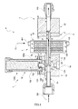
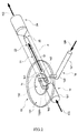
- a liquid material vaporizer A of the present embodiment is, as illustrated in FIGS. 1 and 2 , configured to include: a gas-liquid mixing section 1 for mixing a liquid material LM and a carrier gas CG to generate a gas-liquid mixture GL; a heating type vaporizing section 2 for vaporizing the gas-liquid mixture GL from the gas-liquid mixing section 1 and exhausting the vaporized gas outside with an assistance of the carrier gas CG; a connecting section 3 that is intended for making a connection between the gas-liquid mixing section 1 and the vaporizing section 2 and has inside a flow path for the gas-liquid mixture GL or the like; and a connecting section cooling section 4 for cooling the connecting section 3.
- the respective sections are specifically described below.
- the gas-liquid mixing section 1 is configured to include: a substantially rectangular-shaped main body block 11 having three different flow paths 1a to 1c inside; a flow rate controlling section 12 provided on an upper surface side of the main body block 11; a gas-liquid mixing chamber 13 formed in a space sandwiched between the main body block 11 and the flow rate controlling section 12.
- the main body block 11 is formed of a metal material having high thermal and corrosion resistance, such as stainless steel, and configured to be heatable with a heater 11H provided on a lower end side of the three flow paths 1a to 1c.
- the three flow paths 1a to 1c respectively refer to: a liquid material introduction path 1a for introducing the liquid material LM into the gas-liquid mixing chamber 13; a carrier gas introduction path 1b for introducing the carrier gas CG into the gas-liquid mixing chamber 13; and a gas-liquid mixture exhaust path 1c for exhausting the gas-liquid mixture GL generated in the gas-liquid mixing chamber 13.
- the liquid material introduction path 1a is, as illustrated in FIG. 2 and other drawings, one having a substantially L shape, as viewed from side, including: a liquid material introduction path horizontal section 1a1 extending in a horizontal direction; and a liquid material introduction path rising section 1a2 in which a gas-liquid mixing chamber 13 side of the liquid material introduction path horizontal section 1a1 is risen in a substantially vertical direction.
- a diameter of the liquid material introduction path horizontal section 1a1 is made substantially equal to that of the liquid material introduction path rising section 1a2.
- the carrier gas introduction path 1b is, as illustrated in FIG. 2 and other drawings, one having a substantially L shape, as viewed from side, including: a carrier gas introduction path horizontal section 1b1 extending in a horizontal direction; and a carrier gas introduction path rising section 1b2 in which a gas-liquid mixing chamber 13 side of the carrier gas introduction path horizontal section 1b1 is risen in a substantially vertical direction.
- a diameter of the carrier gas introduction path horizontal section 1b1 is made larger than that of the carrier gas introduction path rising section 1b2.
- the gas-liquid mixture exhaust path 1c is, as illustrated in FIG. 2 and other drawings, one having a substantially L shape, as viewed from side, including: a gas-liquid mixture exhaust path horizontal section 1c1 extending in a horizontal direction; and a gas-liquid mixture exhaust path rising section lc2 in which a gas-liquid mixing chamber 13 side of the gas-liquid mixture exhaust path horizontal section 1c1 is risen in a substantially vertical direction.
- a diameter of the gas-liquid mixture exhaust path horizontal section 1c1 is made equal to that of the gas-liquid mixture exhaust path rising section 1c2.
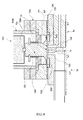
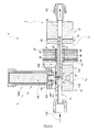
- the flow rate controlling section 12 is, as illustrated in FIGS. 3 and 4 and other drawings, configured to include: a thin disk-like diaphragm 121 arranged in a position where a concave portion 131 of the main body block 11 can be covered; a substantially cylindrical shaft section 120 provided in the center of the diaphragm 121; a piezo actuator 122 brought into abutting contact with an upper end part of the shaft section 120 via a sphere 12x; and a biasing member 123 for constantly biasing the shaft section 120 upward, and these respective components are contained inside a valve block 124a and also inside a substantially tubular housing 124b provided upright on an upper part of the valve block 124a.
- the valve block 124a is fitted onto the main body block 11 via a spacer SP and an O-ring OR.
- the diaphragm 121 when the diaphragm 121 is subjected to a pressing force (pressing force larger than a biasing force by the biasing member 123) downward by the piezo actuator 122 via the shaft section 120, it is displaced convexly downward to decrease a volume inside the gas-liquid mixing chamber 13 formed between the diaphragm 121 and a valve seat 132, and block an opening of the liquid material introduction path rising section 1a2 by a lower end surface 120x of the shaft section 120 (see FIG.
- the diaphragm 121 and the lower end surface 120x of the shaft section 120 are kept at a level spaced from the valve seat 132 (by an amount equal to a thickness of the spacer SP), and the volume inside the gas-liquid mixing chamber 13 can be appropriately ensured (see FIG. 4 ).
- the gas-liquid mixing chamber 13 is one formed in a space sandwiched between the concave portion 131 in which an upper surface of the main body block 11 is concaved in a substantially dish-like shape and the valve seat 132 of a circular shape as viewed planarly that is arranged in the center of the concave portion 131 and provided at a level higher than a bottom level of the concave portion 131, and an after-mentioned lower end surface of the diaphragm 121 of the flow rate controlling section 12 (see FIG. 4 ).
- valve seat 132 is provided with a mixing groove 132m of a substantially oval shape as viewed planarly. Further, in the mixing groove 132m, the carrier gas introduction path rising section 1b2 is opened, and the gas-liquid mixture exhaust path rising section 1c2 is opened.
- the vaporizing section 2 is configured to include: a preheating block 21; a vaporizing block 22 provided on a side of the preheating block 21 opposite to the gas-liquid mixing section 1; a gas introduction path 23 that is provided in substantially the center of the preheating block 21 and passes through in a thickness direction of the preheating block 22; a gas exhaust path 24 that is provided in substantially the center of the vaporizing block 22 and passes through in a thickness direction of the vaporizing block 22; and a nozzle section 25 provided at a connecting section between the gas introduction path 23 and the gas exhaust path 24.
- the preheating block 21 is one formed of a metal material having high thermal conductivity, such as aluminum.
- the vaporizing block 22 is one formed of a metal material having high thermal and corrosion resistance, such as stainless steel. Also, the vaporizing block 22 incorporates a heater (not shown). By the heater, a whole of the vaporizing block 22 including the nozzle section 25 is adapted to be heated to and retained at a temperature (e.g., approximately 300 degrees C) considerably higher than a heating and retaining temperature of the main body block 11.
- a temperature e.g., approximately 300 degrees C
- the gas introduction path 23 is one formed by using an after-mentioned internal flow path of a pipe member P.
- the gas exhaust path 24 is a substantially straight pipe shaped one of which an end on the nozzle section 25 side is formed in a conic shape.
- an outer diameter of the gas exhaust path 24 is set larger than that of the gas introduction path 23.
- a downstream side of the gas exhaust path 24 is connected to a pipeline (not shown) to semiconductor manufacturing equipment.
- the nozzle section 25 is considerably small as compared with diameters and lengths of the gas introduction path 23 and the gas exhaust path 24, and has a diameter and length of, for example, 1.0 mm or less and approximately 1.0 mm, respectively.
- the gas-liquid mixture GL introduced through the gas introduction path 23 flows, and upon the flow, the liquid material LM contained in the gas-liquid mixture GL is depressurized and thereby vaporized, and a gas generated by the vaporization is mixed with the carrier gas CG to become a gas mixture KG.
- the connecting section 3 is one having an internal flow path 31 for introducing inside the gas-liquid mixture GL and carrier gas CG from the gas-liquid mixture exhaust path 1c and exhausting them toward the gas exhaust path 23 of the vaporizing section 2.
- the internal flow path 31 of the connecting section 3, the gas-liquid mixture exhaust path horizontal section 1c1 of the gas-liquid mixing section 1, and the gas introduction path 23 of the vaporizing section 2 are adapted to be formed by using the internal flow path of the common pipe member P.
- the connecting section cooling section 4 is one of a "forced air cooling type" provided with a plurality of connecting section cooling fins 41 that are externally supplied with a cooling gas CL and fitted to the connecting section 3. Also, the connecting section cooling fins 41 respectively use the same thin plate like fins. Also, the connecting section cooling fins 41 are arrayed at given intervals not so as to prevent the flow of the cooling gas CL. Further, the plurality of connecting section cooling fins 41 are arranged in a cooling case 42 having an inlet 421 for introducing inside the cooling gas CL and an outlet 422 for exhausting outside the cooling gas having been used for cooling.
- the liquid material LM through the liquid material introduction path 1a is introduced into the mixing groove 132 with a flow rate thereof into the mixing groove 132m being controlled by the lower end surface 120x of the shaft section 120 driven by the piezo actuator 122, and also the carrier gas CG is introduced into the mixing groove 132m through the carrier gas introduction path 1b.
- the liquid material LM and carrier gas CG are mixed with each other in the mixing groove 132m, and then exhausted into the gas-liquid mixture exhaust path 1c as the gas-liquid mixture GL.
- the gas-liquid mixture GL further reaches the vaporizing section 2 through the internal flow path 31 of the connecting section 3.
- the connecting section 3 is cooled by the connecting section cooling section 4. This enables heat of the vaporizing section 2 to be suppressed from transferring toward the gas-liquid mixing section 1, and the gas-liquid mixture GL passing through the internal flow path 31 and the like of the connecting section 3 to be suppressed from being affected by energy of the heat. Specifically, if a temperature due to the heat of the vaporizing section 2 is approximately 300 degrees C and the connecting section cooling section 4 is absent, a temperature of the gas-liquid mixing section 1 is approximately 100 degrees C, whereas if the connecting section cooling section 4 is present, the temperature of the gas-liquid mixing section 1 can be reduced to approximately 60 degrees C.
- the liquid material LM formed by, for example dissolving a high boiling point solute in a low boiling point material solvent is vaporized, there does not arise a problem that only the low boiling point material solvent is vaporized, and the high boiling point solute becomes a residue in the gas-liquid mixture exhaust path horizontal section 1c1 of the gas-liquid mixing section 1, the internal flow path 31 of the connecting section 3, the gas introduction path 23 of the vaporizing section 2, or the diaphragm 121 for liquid flow rate control inside the gas-liquid mixing section 1, which blocks the internal flow path of the connecting section 3 or the diaphragm 121.
- the gas-liquid mixture GL having been introduced into the gas introduction path 23 of the vaporizing section 2 in a manner described above is further introduced into the nozzle section 25, the liquid material LM contained in the gas-liquid mixture GL is depressurized and thereby vaporized in the nozzle section 25. Then, the gas generated by the vaporization is mixed with the carrier gas CG to become the gas mixture KG, which is then exhausted outside.
- the connecting section cooling section 4 cools the connecting section 3, whereby the heat of the vaporizing section 2 can be suppressed from transferring toward the gas-liquid mixing section 1, and the gas-liquid mixture GL passing through the flow path inside the connecting section 3 can be suppressed from being affected by the energy of the heat.
- liquid material LM formed by, for example, dissolving a high boiling point solute in a low boiling point material solvent is vaporized, there can be prevented a problem that only the low boiling point material solvent is vaporized, and the high boiling point solute becomes a residue in the gas-liquid mixture exhaust path horizontal section 1c1 of the gas-liquid mixing section 1, the internal flow path 31 of the connecting section 3, the gas introduction path 23 of the vaporizing section 2, or the diaphragm 121 for liquid flow rate control inside the gas-liquid mixing section 1, which blocks each of the flow paths or the diaphragm 121.
- the excellent liquid material vaporizer A capable of, even if the liquid material LM including a plurality of materials having different boiling points is vaporized, preventing the residue from being generated, and preferably performing the vaporization.
- the connecting section cooling section 4 substantially entirely cools the connecting section 3, and, in addition to this, the connecting section cooling section 4 is configured to include the plurality of connecting section cooling fins 41 that are supplied with the cooling gas CL and fitted to the connecting section 3, so that, even if the vaporizing section 2 is heated to and retained at approximately 300 degrees C, the gas-liquid mixing section 1 can be cooled to approximately 60 degrees C by an action of the connecting section cooling section 4. Accordingly, even with such a simple structure, a high cooling effect can be obtained in the connecting section cooling section 4, and the problem of generation of the residue can be preferably prevented, while ensuring a function of the high temperature type vaporizing section 2.
- an aspect including a cooling gas cooling section 43 for preliminarily cooling the cooling gas CL used for cooling the connecting section cooling fins 41.
- an aspect includes one adapted such that the cooling gas cooling section 43 includes: a plurality of cooling gas cooling fins 431; and a cooling gas cooling Peltier element 432 configured to be fitted toward a flow path for the cooling gas CL on a cooling side thereof and fitted to the cooling gas cooling fins 431 on a heat generating side thereof.
- the connecting section cooling section 4 is configured to include: a connecting section cooling Peltier element 47 fitted to the connecting section 3 on a cooling side thereof; and a plurality of Peltier element cooling fins 48 fitted to a heating side of the connecting section cooling Peltier element 47.
- liquid material vaporizer A is configured to vertically arrange the gas-liquid mixing section 1, the connecting section 3 fitted with the connecting section cooling section 4, and the vaporizing section 2 in this order from the top.
- a cooling method in the connecting section cooling section is not limited to that in the present embodiment, but an appropriate cooling method may be employed depending on an embodiment, such as water cooling using liquid for cooling.
- a backflow prevention nozzle for preventing the liquid material supplied to the gas-liquid mixing chamber from flowing back into the carrier gas introduction path is further provided in addition to each of the above-described embodiments.
- a specific aspect of the backflow prevention nozzle includes, for example, a nozzle section for backflow prevention described in Japanese Unexamined Patent Publication No. 2003-273025 (pages 3 and 4, and FIG. 2 ).
- the gas introduction path 24 is hollow, lower pressure inside the path causes a gas density of the gas mixture KG to be reduced, resulting in a longer intermolecular distance. For this reason, heat becomes difficult to transfer, and therefore the gas mixture KG cannot be preferably exhausted outside. That is, the vaporization may be affected. For this reason, by arranging an unshown filling material in the gas introduction path 24, the heat transfer can be facilitated to preferably perform the vaporization even if the pressure inside the path is low.
- the filling material a metal material such as titanium having high thermal conductivity can be used.
- a plurality of granular (spherical) filling materials may be arranged in the path, or one or a plurality of filling materials formed in a spiral shape by twisting flat plates (so-called static mixer) may be arranged in the path.
- the filling materials of the spiral shape result in lower pressure loss when arranged in the path, as compared with the granular filling materials, and therefore the vaporization can be more preferably performed.
- an unshown filter may be provided in a rear stage of the nozzle section 25.
- Providing the filter enables the residue to be trapped even if the residue is generated. Also, even if unvaporized liquid of the gas-liquid mixture GL remains, from which mist is generated, the mist can be eliminated.
- gas-liquid mixing section 1, the vaporizing section 2, the connecting section 3, and the connecting section cooling section 4 may be configured to be respectively decomposable. This enables the respective sections to be easily maintained.
- the liquid material vaporizer having such configuration according to the present invention can prevent a residue from being generated to preferably perform the vaporization even if a liquid material including a plurality of materials having different boiling points is vaporized, and is therefore preferably used as, for example, a liquid material vaporizer for vaporizing various liquid materials used in semiconductor manufacturing.
Landscapes
- Chemical & Material Sciences (AREA)
- Engineering & Computer Science (AREA)
- General Chemical & Material Sciences (AREA)
- Chemical Kinetics & Catalysis (AREA)
- Materials Engineering (AREA)
- Mechanical Engineering (AREA)
- Metallurgy (AREA)
- Organic Chemistry (AREA)
- Manufacturing & Machinery (AREA)
- Physics & Mathematics (AREA)
- Condensed Matter Physics & Semiconductors (AREA)
- General Physics & Mathematics (AREA)
- Computer Hardware Design (AREA)
- Microelectronics & Electronic Packaging (AREA)
- Power Engineering (AREA)
- Chemical Vapour Deposition (AREA)
- Feeding, Discharge, Calcimining, Fusing, And Gas-Generation Devices (AREA)
- Filling Or Discharging Of Gas Storage Vessels (AREA)
Applications Claiming Priority (2)
| Application Number | Priority Date | Filing Date | Title |
|---|---|---|---|
| JP2006103803 | 2006-04-05 | ||
| PCT/JP2007/057593 WO2007114474A1 (fr) | 2006-04-05 | 2007-04-04 | Vaporiseur de matiere liquide |
Publications (2)
| Publication Number | Publication Date |
|---|---|
| EP2009137A1 true EP2009137A1 (fr) | 2008-12-31 |
| EP2009137A4 EP2009137A4 (fr) | 2010-03-24 |
Family
ID=38563735
Family Applications (1)
| Application Number | Title | Priority Date | Filing Date |
|---|---|---|---|
| EP07741029A Withdrawn EP2009137A4 (fr) | 2006-04-05 | 2007-04-04 | Vaporiseur de matiere liquide |
Country Status (6)
| Country | Link |
|---|---|
| US (1) | US8280235B2 (fr) |
| EP (1) | EP2009137A4 (fr) |
| JP (2) | JP5090341B2 (fr) |
| KR (1) | KR101058976B1 (fr) |
| CN (3) | CN102912319B (fr) |
| WO (1) | WO2007114474A1 (fr) |
Families Citing this family (17)
| Publication number | Priority date | Publication date | Assignee | Title |
|---|---|---|---|---|
| US8755679B2 (en) | 2006-04-05 | 2014-06-17 | Horiba Stec, Co., Ltd. | Liquid material vaporizer |
| JP5004890B2 (ja) * | 2008-07-24 | 2012-08-22 | 株式会社日立国際電気 | 気化器、基板処理装置及び半導体装置の製造方法 |
| US9454158B2 (en) | 2013-03-15 | 2016-09-27 | Bhushan Somani | Real time diagnostics for flow controller systems and methods |
| JP6151943B2 (ja) * | 2013-03-26 | 2017-06-21 | 株式会社日立国際電気 | 基板処理装置及び半導体装置の製造方法 |
| JP6186179B2 (ja) * | 2013-05-31 | 2017-08-23 | 株式会社堀場エステック | 攪拌器及び攪拌器の製造方法 |
| KR102108802B1 (ko) | 2014-05-07 | 2020-05-11 | 현대자동차주식회사 | 연소실로 유입되는 흡기의 온도를 제어하기 위한 에어히터 및 그 작동방법 |
| KR102409471B1 (ko) | 2014-12-22 | 2022-06-16 | 가부시키가이샤 호리바 에스텍 | 유체 가열기 |
| JP6450469B2 (ja) * | 2015-11-10 | 2019-01-09 | 東京エレクトロン株式会社 | 気化器、成膜装置及び温度制御方法 |
| JP6675865B2 (ja) * | 2015-12-11 | 2020-04-08 | 株式会社堀場エステック | 液体材料気化装置 |
| KR102483924B1 (ko) | 2016-02-18 | 2023-01-02 | 삼성전자주식회사 | 기화기 및 이를 구비하는 박막 증착 장치 |
| US10983537B2 (en) | 2017-02-27 | 2021-04-20 | Flow Devices And Systems Inc. | Systems and methods for flow sensor back pressure adjustment for mass flow controller |
| JP7184794B2 (ja) * | 2017-10-23 | 2022-12-06 | 株式会社堀場エステック | 気化装置及び気化装置用分離器 |
| JP7223496B2 (ja) * | 2017-12-14 | 2023-02-16 | 株式会社堀場エステック | 混合器及び気化装置 |
| KR102250139B1 (ko) | 2018-01-23 | 2021-05-10 | (주)티티에스 | 액체 소스 기화 장치 및 기화 방법 |
| CN110643975B (zh) * | 2018-06-27 | 2021-09-28 | 东北大学 | 一种金属有机化学源液体的蒸发输运装置 |
| JP7402801B2 (ja) * | 2018-08-24 | 2023-12-21 | 株式会社堀場エステック | 気化器、液体材料気化装置、及び気化方法 |
| WO2024080180A1 (fr) * | 2022-10-12 | 2024-04-18 | 株式会社堀場エステック | Vaporisateur de matériau liquide et procédé de vaporisation de matériau liquide |
Citations (1)
| Publication number | Priority date | Publication date | Assignee | Title |
|---|---|---|---|---|
| US6424800B1 (en) * | 1999-09-21 | 2002-07-23 | Samsung Electronics Co., Ltd. | Bubbler |
Family Cites Families (13)
| Publication number | Priority date | Publication date | Assignee | Title |
|---|---|---|---|---|
| DE69312436T2 (de) * | 1992-12-15 | 1998-02-05 | Applied Materials Inc | Verdampfung von flüssigen Reaktionspartnern für CVD |
| US5630878A (en) * | 1994-02-20 | 1997-05-20 | Stec Inc. | Liquid material-vaporizing and supplying apparatus |
| US5520001A (en) * | 1994-02-20 | 1996-05-28 | Stec, Inc. | Vapor controller |
| JP3893177B2 (ja) * | 1996-11-12 | 2007-03-14 | 松下電器産業株式会社 | 気化装置、cvd装置及び薄膜製造方法 |
| US6409839B1 (en) * | 1997-06-02 | 2002-06-25 | Msp Corporation | Method and apparatus for vapor generation and film deposition |
| US6258170B1 (en) * | 1997-09-11 | 2001-07-10 | Applied Materials, Inc. | Vaporization and deposition apparatus |
| CN1091170C (zh) * | 1998-02-18 | 2002-09-18 | 佛山市扬戈热处理有限公司 | 一种热处理工艺及设备 |
| JP2000345345A (ja) * | 1999-06-04 | 2000-12-12 | Mitsubishi Electric Corp | Cvd装置およびcvd装置用気化装置 |
| JP2001004095A (ja) * | 1999-06-18 | 2001-01-09 | Nippon M K S Kk | 気化器 |
| JP4251429B2 (ja) | 2001-11-28 | 2009-04-08 | 株式会社堀場エステック | 液体材料気化装置 |
| JP3881569B2 (ja) | 2002-03-13 | 2007-02-14 | 株式会社堀場エステック | 液体材料気化装置 |
| JP4276409B2 (ja) * | 2002-06-21 | 2009-06-10 | 株式会社堀場エステック | 液体材料気化装置 |
| JP4607474B2 (ja) * | 2004-02-12 | 2011-01-05 | 東京エレクトロン株式会社 | 成膜装置 |
-
2007
- 2007-04-04 JP JP2008508715A patent/JP5090341B2/ja active Active
- 2007-04-04 US US12/295,862 patent/US8280235B2/en active Active
- 2007-04-04 KR KR1020087024259A patent/KR101058976B1/ko active IP Right Grant
- 2007-04-04 EP EP07741029A patent/EP2009137A4/fr not_active Withdrawn
- 2007-04-04 CN CN201210352861.7A patent/CN102912319B/zh active Active
- 2007-04-04 CN CNA2007800109411A patent/CN101410548A/zh active Pending
- 2007-04-04 CN CN201510413970.9A patent/CN105256288A/zh active Pending
- 2007-04-04 WO PCT/JP2007/057593 patent/WO2007114474A1/fr active Application Filing
-
2012
- 2012-03-12 JP JP2012054917A patent/JP5475817B2/ja active Active
Patent Citations (1)
| Publication number | Priority date | Publication date | Assignee | Title |
|---|---|---|---|---|
| US6424800B1 (en) * | 1999-09-21 | 2002-07-23 | Samsung Electronics Co., Ltd. | Bubbler |
Non-Patent Citations (1)
| Title |
|---|
| See also references of WO2007114474A1 * |
Also Published As
| Publication number | Publication date |
|---|---|
| KR20080110603A (ko) | 2008-12-18 |
| JPWO2007114474A1 (ja) | 2009-08-20 |
| JP5475817B2 (ja) | 2014-04-16 |
| JP5090341B2 (ja) | 2012-12-05 |
| JP2012177193A (ja) | 2012-09-13 |
| CN105256288A (zh) | 2016-01-20 |
| US8280235B2 (en) | 2012-10-02 |
| US20090097831A1 (en) | 2009-04-16 |
| KR101058976B1 (ko) | 2011-08-23 |
| WO2007114474A1 (fr) | 2007-10-11 |
| EP2009137A4 (fr) | 2010-03-24 |
| CN102912319A (zh) | 2013-02-06 |
| CN102912319B (zh) | 2014-12-10 |
| CN101410548A (zh) | 2009-04-15 |
Similar Documents
| Publication | Publication Date | Title |
|---|---|---|
| EP2009137A1 (fr) | Vaporiseur de matiere liquide | |
| US8755679B2 (en) | Liquid material vaporizer | |
| JP5732025B2 (ja) | 基板処理システムにおける材料蒸着方法及び装置 | |
| US20130195432A1 (en) | Trichlorosilane vaporization system | |
| JP6675865B2 (ja) | 液体材料気化装置 | |
| KR20140094657A (ko) | 액체재료 기화장치 | |
| EP1757359A1 (fr) | Générateur de nanoparticules | |
| TWI410372B (zh) | 合成碳奈米管的裝置 | |
| JP2003273025A (ja) | 液体材料気化装置 | |
| JP2007046084A (ja) | 気化器並びにこれを用いた液体気化供給装置 | |
| KR101501311B1 (ko) | 액체 재료 기화 장치 | |
| KR100322411B1 (ko) | 액체원료 기화장치 | |
| EP2682980B1 (fr) | Vaporisateur, barre centrale utilisée dans celle-ci et procédé de vaporisation d'une matière portée par un gaz porteur | |
| CN111447982B (zh) | 用于蒸汽发生和薄膜沉积的设备和方法 | |
| JP2003163168A (ja) | 液体材料気化装置 | |
| Allen | Two-phase flow in small channels and the implications for PEM fuel cell operation | |
| JP2006346653A (ja) | 加圧式マイクロリアクタシステム | |
| US20140199586A1 (en) | Apparatus for evaporating liquid hydrocarbon compounds or of liquids in which hydrocarbon compounds are contained as well as use of same | |
| JP5211426B2 (ja) | マイクロリアクタシステム | |
| JP5193826B2 (ja) | 液体材料気化装置 | |
| JP2005268367A (ja) | 液体材料気化装置 | |
| JP2021107312A (ja) | 排ガス冷却装置、フラーレンの製造装置及びフラーレンの製造方法 | |
| JP5185726B2 (ja) | 気化器、薄膜形成装置及びmocvd装置 | |
| JP2005328085A (ja) | Mocvd用気化器及び原料溶液の気化方法 | |
| JP2004006928A (ja) | Mocvd用気化器及び原料溶液の気化方法 |
Legal Events
| Date | Code | Title | Description |
|---|---|---|---|
| PUAI | Public reference made under article 153(3) epc to a published international application that has entered the european phase |
Free format text: ORIGINAL CODE: 0009012 |
|
| 17P | Request for examination filed |
Effective date: 20081007 |
|
| AK | Designated contracting states |
Kind code of ref document: A1 Designated state(s): AT BE BG CH CY CZ DE DK EE ES FI FR GB GR HU IE IS IT LI LT LU LV MC MT NL PL PT RO SE SI SK TR |
|
| AX | Request for extension of the european patent |
Extension state: AL BA HR MK RS |
|
| RBV | Designated contracting states (corrected) |
Designated state(s): DE FR GB NL |
|
| A4 | Supplementary search report drawn up and despatched |
Effective date: 20100219 |
|
| 17Q | First examination report despatched |
Effective date: 20100928 |
|
| DAX | Request for extension of the european patent (deleted) | ||
| STAA | Information on the status of an ep patent application or granted ep patent |
Free format text: STATUS: THE APPLICATION IS DEEMED TO BE WITHDRAWN |
|
| 18D | Application deemed to be withdrawn |
Effective date: 20121101 |