EP2007611B1 - Verfahren zur regelung des druckes in einem elektronisch gesteuerten bremssystem und elektronisches bremssystem - Google Patents
Verfahren zur regelung des druckes in einem elektronisch gesteuerten bremssystem und elektronisches bremssystem Download PDFInfo
- Publication number
- EP2007611B1 EP2007611B1 EP07727291.2A EP07727291A EP2007611B1 EP 2007611 B1 EP2007611 B1 EP 2007611B1 EP 07727291 A EP07727291 A EP 07727291A EP 2007611 B1 EP2007611 B1 EP 2007611B1
- Authority
- EP
- European Patent Office
- Prior art keywords
- brake
- motorcycle
- wheel
- brake system
- stationary
- Prior art date
- Legal status (The legal status is an assumption and is not a legal conclusion. Google has not performed a legal analysis and makes no representation as to the accuracy of the status listed.)
- Active
Links
- 238000000034 method Methods 0.000 title claims description 21
- 230000001105 regulatory effect Effects 0.000 title claims 2
- 230000004913 activation Effects 0.000 claims description 11
- 230000000694 effects Effects 0.000 claims description 8
- 238000001514 detection method Methods 0.000 description 8
- 241000238876 Acari Species 0.000 description 6
- 239000000463 material Substances 0.000 description 3
- 230000006978 adaptation Effects 0.000 description 2
- 239000012530 fluid Substances 0.000 description 2
- 238000002955 isolation Methods 0.000 description 2
- 230000000712 assembly Effects 0.000 description 1
- 238000000429 assembly Methods 0.000 description 1
- 238000010276 construction Methods 0.000 description 1
Images
Classifications
-
- B—PERFORMING OPERATIONS; TRANSPORTING
- B60—VEHICLES IN GENERAL
- B60T—VEHICLE BRAKE CONTROL SYSTEMS OR PARTS THEREOF; BRAKE CONTROL SYSTEMS OR PARTS THEREOF, IN GENERAL; ARRANGEMENT OF BRAKING ELEMENTS ON VEHICLES IN GENERAL; PORTABLE DEVICES FOR PREVENTING UNWANTED MOVEMENT OF VEHICLES; VEHICLE MODIFICATIONS TO FACILITATE COOLING OF BRAKES
- B60T8/00—Arrangements for adjusting wheel-braking force to meet varying vehicular or ground-surface conditions, e.g. limiting or varying distribution of braking force
- B60T8/17—Using electrical or electronic regulation means to control braking
- B60T8/1701—Braking or traction control means specially adapted for particular types of vehicles
- B60T8/1706—Braking or traction control means specially adapted for particular types of vehicles for single-track vehicles, e.g. motorcycles
-
- B—PERFORMING OPERATIONS; TRANSPORTING
- B60—VEHICLES IN GENERAL
- B60T—VEHICLE BRAKE CONTROL SYSTEMS OR PARTS THEREOF; BRAKE CONTROL SYSTEMS OR PARTS THEREOF, IN GENERAL; ARRANGEMENT OF BRAKING ELEMENTS ON VEHICLES IN GENERAL; PORTABLE DEVICES FOR PREVENTING UNWANTED MOVEMENT OF VEHICLES; VEHICLE MODIFICATIONS TO FACILITATE COOLING OF BRAKES
- B60T8/00—Arrangements for adjusting wheel-braking force to meet varying vehicular or ground-surface conditions, e.g. limiting or varying distribution of braking force
- B60T8/26—Arrangements for adjusting wheel-braking force to meet varying vehicular or ground-surface conditions, e.g. limiting or varying distribution of braking force characterised by producing differential braking between front and rear wheels
- B60T8/261—Arrangements for adjusting wheel-braking force to meet varying vehicular or ground-surface conditions, e.g. limiting or varying distribution of braking force characterised by producing differential braking between front and rear wheels specially adapted for use in motorcycles
-
- B—PERFORMING OPERATIONS; TRANSPORTING
- B60—VEHICLES IN GENERAL
- B60T—VEHICLE BRAKE CONTROL SYSTEMS OR PARTS THEREOF; BRAKE CONTROL SYSTEMS OR PARTS THEREOF, IN GENERAL; ARRANGEMENT OF BRAKING ELEMENTS ON VEHICLES IN GENERAL; PORTABLE DEVICES FOR PREVENTING UNWANTED MOVEMENT OF VEHICLES; VEHICLE MODIFICATIONS TO FACILITATE COOLING OF BRAKES
- B60T8/00—Arrangements for adjusting wheel-braking force to meet varying vehicular or ground-surface conditions, e.g. limiting or varying distribution of braking force
- B60T8/32—Arrangements for adjusting wheel-braking force to meet varying vehicular or ground-surface conditions, e.g. limiting or varying distribution of braking force responsive to a speed condition, e.g. acceleration or deceleration
- B60T8/321—Arrangements for adjusting wheel-braking force to meet varying vehicular or ground-surface conditions, e.g. limiting or varying distribution of braking force responsive to a speed condition, e.g. acceleration or deceleration deceleration
- B60T8/3225—Systems specially adapted for single-track vehicles, e.g. motorcycles
-
- B—PERFORMING OPERATIONS; TRANSPORTING
- B60—VEHICLES IN GENERAL
- B60T—VEHICLE BRAKE CONTROL SYSTEMS OR PARTS THEREOF; BRAKE CONTROL SYSTEMS OR PARTS THEREOF, IN GENERAL; ARRANGEMENT OF BRAKING ELEMENTS ON VEHICLES IN GENERAL; PORTABLE DEVICES FOR PREVENTING UNWANTED MOVEMENT OF VEHICLES; VEHICLE MODIFICATIONS TO FACILITATE COOLING OF BRAKES
- B60T8/00—Arrangements for adjusting wheel-braking force to meet varying vehicular or ground-surface conditions, e.g. limiting or varying distribution of braking force
- B60T8/32—Arrangements for adjusting wheel-braking force to meet varying vehicular or ground-surface conditions, e.g. limiting or varying distribution of braking force responsive to a speed condition, e.g. acceleration or deceleration
- B60T8/34—Arrangements for adjusting wheel-braking force to meet varying vehicular or ground-surface conditions, e.g. limiting or varying distribution of braking force responsive to a speed condition, e.g. acceleration or deceleration having a fluid pressure regulator responsive to a speed condition
- B60T8/40—Arrangements for adjusting wheel-braking force to meet varying vehicular or ground-surface conditions, e.g. limiting or varying distribution of braking force responsive to a speed condition, e.g. acceleration or deceleration having a fluid pressure regulator responsive to a speed condition comprising an additional fluid circuit including fluid pressurising means for modifying the pressure of the braking fluid, e.g. including wheel driven pumps for detecting a speed condition, or pumps which are controlled by means independent of the braking system
- B60T8/4072—Systems in which a driver input signal is used as a control signal for the additional fluid circuit which is normally used for braking
Definitions
- the invention relates to a method according to the preamble of claim 1 and to an electronic brake system according to the preamble of claim 8.
- the motorcycle has evolved over the past few decades from a cost-effective means of transportation to a recreational vehicle, in which increasingly both the safety and the comfort of the driver is brought to the fore.
- ABS anti-lock braking systems
- motorcycles each have one actuator for each of the two brake circuits. Most of the front brake is operated by a "hand brake lever” and the rear brake by a "foot brake lever”.
- Integral brake system a brake system, in addition to the operation of the handbrake lever and the foot brake lever the brake of the second brake circuit is braked by an active pressure build-up. By pressing a single actuator so both brakes can be controlled. If both brakes are activated when the hand and foot brake levers are actuated, this is referred to as a full integral brake. However, combinations are also possible in which one brake lever acts on one wheel and the other brake lever acts on both wheels (partial integral brake). Integral brake systems for motorcycles are for example from the DE 38 03 563 A1 and DE 103 16 351 A1 known.
- An active build-up of brake pressure is always accompanied by noise and wear.
- valves and a pump of the electronic brake system are required and thus ensure a not inconsiderable noise development.
- the noise for the driver is quite perceptible and can be disturbing.
- the invention is based on the idea to avoid an active pressure build-up in a brake circuit when it is not necessary.
- an active build up of brake pressure in a brake circuit is not necessary when the vehicle, in particular the motorcycle, is at a standstill or moving at a very low speed, since in this case no increased braking effect is needed.
- the invention relates to a method for controlling the brake pressure in an integral brake system for a motorcycle and an integral brake system for a motorcycle.
- the integral brake system comprises at least one pump for the active construction of brake pressure at at least one wheel brake.
- the activation event is an actuation of a brake actuation element of a motorcycle with which a front wheel and a rear wheel brake are actuated.
- an actuation of a brake actuation element which is equipped with an integral function always produces an active pressure build-up in the other, not directly to the actuator associated wheel brake performed. This is prevented according to the invention when the braking effect is not needed.
- the vehicle is stationary or nearly stationary when a variable, which is a measure of the speed of the vehicle or a measure of a wheel rotational speed, falls below a predetermined limit.
- a variable standstill detection or “almost standstill detection” is possible.
- the limit value is selected as a function of the type and / or the model of the vehicle.
- a vehicle-specific adaptation of the method according to the invention is possible.
- the standstill detection or “almost standstill detection” is carried out on the basis of a respective wheel speed signal from a front wheel and a rear wheel. So a reliable detection is possible.
- the standstill or near-stopping of the vehicle is recognized by it, if for a given time interval, the number of signal edges of at least one wheel speed signal is smaller than a predetermined threshold. So a sensitive motion detection is possible.
- the brake system according to the invention comprises a front brake and a rear wheel brake and at least one actuating element with which the front wheel brake and the rear wheel brake are simultaneously controllable.
- the integral brake system comprises an electronic control device for controlling the brake pressures at the front wheel brake and at the rear wheel brake.
- the integral brake system preferably includes wheel speed sensors for measuring the wheel speeds of the front wheel and / or the rear wheel, wherein the wheel speed sensors are connected to the control device.
- a first preferred embodiment of the brake system is an integral brake with a first brake actuator for actuating a first master cylinder, which is connected via a hydraulic brake pressure control device to a first wheel brake, which is arranged either on the front or on the rear wheel, and with a second wheel brake, which is arranged on that front or rear wheel, which does not have the first wheel brake, wherein at the same time by actuation of the first brake actuating element, the first and the second wheel brake can be controlled.
- actuation of the first brake actuation element is carried out by a pump and a suitable wiring of the valves of the brake system, an active pressure build-up on the second wheel brake.
- the integral brake comprises a second brake lever for actuating a second master brake cylinder which is connected to the second wheel brake via a second hydraulic brake pressure control device.
- the second brake actuating element By actuating the second brake actuating element, the first and the second wheel brake (full integral brake) or only the second wheel brake (partial integral brake) are simultaneously activated.
- An advantage of the invention is that it can be decided by senible motion detection whether or not the motorcycle is in motion, and thus a decision as to whether or not active pressure build-up is needed to assist the driver can be made.
- Another advantage of the invention lies in the reduction of the noise of the electronic brake system. Especially in standstill situations, the electronic brake system according to the invention is even no longer perceptible.
- the material wear in the electronic brake system is reduced as well, without having to accept a functional disadvantage.
- the inventive method is described below with reference to a motorcycle brake system with partial integral braking function (see Fig. 1 However, it may also be performed in any other brake system in which an active build-up of brake pressure is performed in the presence of an activation event. For example, the method may be performed in a full-integral motorcycle brake system or in a passenger car brake system.
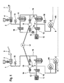
- FIG. 1 an exemplary Operaintegralbremsstrom for a motorcycle is shown schematically.
- This consists of two brake circuits 1, 2, one for the front wheel VR and one for the rear wheel HR, each with a master cylinder 3, 4.
- a hand brake lever 5 the driver directly actuates the front brake 6 and a foot pedal 7, the rear brake 8 is actuated.
- both in the front and rear wheel brake circuit 1, 2 electromagnetically actuated inlet and outlet valves 9, 10 are arranged, wherein each open in the basic position inlet valve 9 is inserted into the brake line of the front and the rear wheel brake circuit 1, 2, respectively associated master cylinder 3, 4 with the front or rear brake 6, 8 connects.
- In the rear wheel brake circuit 2 is also an opening in the basic position of the isolation valve 11.
- Das in Basic position closed exhaust valve 10 is in each case inserted into a return line 12 of each brake circuit which connects the front or rear wheel brake 6, 8, each with a low-pressure accumulator 13 and the suction path 14 of a double-ended pump 15, which operates on the sudizikar.
- the pump 15 is on the pressure side with the brake lines 16 of both brake circuits in conjunction so that in a brake slip control phase a demand-driven return of each of the front and rear brake 6, 8 drained brake fluid volume is ensured in the brake lines 16 both brake circuits.
- the pump pistons of the two pump circuits are driven jointly by an electric motor 17.
- Both brake circuits 1, 2 are according to their circuit design together and independently operable, with the peculiarity that in a manual operation of the master cylinder 3 connected to the front brake 1 not only a brake pressure buildup in the front brake 6, but at the same time an electro-hydraulic brake pressure build-up (active Pressure build-up) in the rear brake 8, by the electric motor 17, the pump 15 is in operation, as soon as due to the rear wheel 2 electrically initiated open position of the changeover valve 18, the pump 15 takes pressure fluid from the master cylinder 4 and promotes the rear brake 8, while the isolation valve 11 in Rear brake circuit 2, the pump pressure side of the master cylinder 4 separates.
- active Pressure build-up active Pressure build-up
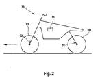
- Fig. 2 shows a schematic representation of a motorcycle.
- Motorcycle 30 with control unit 31 and one wheel speed sensor 32 each on front wheel VR and rear wheel HR moves in the direction indicated by the arrow.
- Control unit 31 is according to the example for the control of brake pressure controls designed for anti-skid control and / or integral braking function.
- the motorcycle 30 is at a standstill or not to avoid a possibly unnecessary pressure build-up.
- the wheel signals of the wheel speed sensors 32 are analyzed by front wheel VR and rear wheel HR.
- the number of incoming wheel signals (ticks) per calculation cycle (Loop) are set in relation to the past time. If sufficient ticks are counted in a specific time window, the motorcycle 30 is considered not at standstill. If less than required or no ticks are counted, then the motorcycle 30 is by definition at a standstill.
- a vehicle speed of 2 km / h or less may be selected, or a corresponding wheel speed or a corresponding number of incoming wheel signals (ticks) per calculation cycle (loop).
- the brake pressure is only 'passive' managed. This means, for example, that the activation of pump 15 and electrical switching valve 18 (EUV) to actively build up brake pressure in the rear wheel brake circuit 2 is prevented.
- EUV electrical switching valve 18
- only the pressure already available in the brake circuit 2 is managed. Thus, it is only possible to follow the driver's request following brake pressure or reduce.
- the driver is also possible to manually build the pressure in the brake circuit 2 by pressing the foot brake pedal 7. This manually established pressure can then also be managed passively by the electronic brake system as described above.
- an optimal braking effect can thus be achieved on the rear wheel HR. This is particularly important in the sense that, especially in such situations, the greatest braking effect can be achieved with the rear wheel HR.
- the noise of the electronic brake system is significantly reduced and is even no longer perceptible in the described standstill situations.
- the material wear is reduced in the electronic brake system, without having to accept a functional disadvantage.
Applications Claiming Priority (2)
| Application Number | Priority Date | Filing Date | Title |
|---|---|---|---|
| DE102006017357 | 2006-04-11 | ||
| PCT/EP2007/052817 WO2007118760A1 (de) | 2006-04-11 | 2007-03-23 | Verfahren zur regelung des druckes in einem elektronisch gesteuerten bremssystem und elektronisches bremssystem |
Publications (2)
| Publication Number | Publication Date |
|---|---|
| EP2007611A1 EP2007611A1 (de) | 2008-12-31 |
| EP2007611B1 true EP2007611B1 (de) | 2014-08-13 |
Family
ID=38109601
Family Applications (1)
| Application Number | Title | Priority Date | Filing Date |
|---|---|---|---|
| EP07727291.2A Active EP2007611B1 (de) | 2006-04-11 | 2007-03-23 | Verfahren zur regelung des druckes in einem elektronisch gesteuerten bremssystem und elektronisches bremssystem |
Country Status (4)
| Country | Link |
|---|---|
| US (1) | US20090115243A1 (ja) |
| EP (1) | EP2007611B1 (ja) |
| JP (1) | JP5391061B2 (ja) |
| WO (1) | WO2007118760A1 (ja) |
Cited By (1)
| Publication number | Priority date | Publication date | Assignee | Title |
|---|---|---|---|---|
| DE102019128982A1 (de) * | 2019-10-28 | 2021-04-29 | Bayerische Motoren Werke Aktiengesellschaft | Bremsenvorrichtung für ein Neigefahrzeug sowie Neigefahrzeug mit einer Bremsenvorrichtung |
Families Citing this family (3)
| Publication number | Priority date | Publication date | Assignee | Title |
|---|---|---|---|---|
| JP2009154799A (ja) * | 2007-12-27 | 2009-07-16 | Yamaha Motor Co Ltd | 制動装置及び該制動装置を備えた鞍乗型車両 |
| EP2311702B1 (en) * | 2009-10-16 | 2012-12-19 | Yamaha Hatsudoki Kabushiki Kaisha | Braking system for motorcycle |
| EP2311701A1 (en) * | 2009-10-16 | 2011-04-20 | Yamaha Hatsudoki Kabushiki Kaisha | Braking system for motorcycle |
Family Cites Families (12)
| Publication number | Priority date | Publication date | Assignee | Title |
|---|---|---|---|---|
| US5404304A (en) * | 1993-11-19 | 1995-04-04 | Delco Electronics Corporation | Vehicle control system for determining verified wheel speed signals |
| DE19640743B4 (de) * | 1996-10-02 | 2008-02-21 | Robert Bosch Gmbh | Verfahren und Vorrichtung zur Steuerung der Bremsanlage eines Fahrzeugs |
| DE19941482B4 (de) * | 1998-09-30 | 2017-11-09 | Robert Bosch Gmbh | Vorrichtung und Verfahren zur Verhinderung des Rückwärtsrollens eines an einem Hang befindlichen Fahrzeuges |
| JP4446504B2 (ja) * | 1998-10-26 | 2010-04-07 | 本田技研工業株式会社 | 自動二輪車の制動装置 |
| JP2003502217A (ja) * | 1999-06-17 | 2003-01-21 | コンティネンタル・テーベス・アクチエンゲゼルシヤフト・ウント・コンパニー・オッフェネ・ハンデルスゲゼルシヤフト | トラクションスリップコントロール方法と装置 |
| DE10047761A1 (de) * | 2000-09-27 | 2002-04-11 | Bosch Gmbh Robert | Verfahren und Vorrichtung zur Steuerung einer Radbremse eines Fahrzeugs |
| JP4155386B2 (ja) * | 2001-05-10 | 2008-09-24 | ボッシュ株式会社 | 自動二輪車のブレーキ制御方法及び装置 |
| EP1277635B1 (en) * | 2001-07-19 | 2008-10-08 | Bosch Corporation | Brake control methods and apparatus for motorcycles |
| DE10316351A1 (de) * | 2003-04-10 | 2004-10-28 | Bayerische Motoren Werke Ag | Integralbremse für Motorräder |
| JP4536389B2 (ja) * | 2004-01-30 | 2010-09-01 | 本田技研工業株式会社 | 自動二輪車のブレーキ装置 |
| JP4137879B2 (ja) * | 2004-12-20 | 2008-08-20 | 本田技研工業株式会社 | 自動二輪車のブレーキ装置 |
| CA2528903C (en) * | 2004-12-20 | 2008-01-15 | Honda Motor Co., Ltd. | Braking device for motorcycle |
-
2007
- 2007-03-23 JP JP2009504669A patent/JP5391061B2/ja active Active
- 2007-03-23 WO PCT/EP2007/052817 patent/WO2007118760A1/de active Application Filing
- 2007-03-23 EP EP07727291.2A patent/EP2007611B1/de active Active
- 2007-03-23 US US12/296,153 patent/US20090115243A1/en not_active Abandoned
Cited By (1)
| Publication number | Priority date | Publication date | Assignee | Title |
|---|---|---|---|---|
| DE102019128982A1 (de) * | 2019-10-28 | 2021-04-29 | Bayerische Motoren Werke Aktiengesellschaft | Bremsenvorrichtung für ein Neigefahrzeug sowie Neigefahrzeug mit einer Bremsenvorrichtung |
Also Published As
| Publication number | Publication date |
|---|---|
| EP2007611A1 (de) | 2008-12-31 |
| WO2007118760A1 (de) | 2007-10-25 |
| US20090115243A1 (en) | 2009-05-07 |
| JP2009533269A (ja) | 2009-09-17 |
| JP5391061B2 (ja) | 2014-01-15 |
Similar Documents
| Publication | Publication Date | Title |
|---|---|---|
| EP2032404B1 (de) | Verfahren zur regelung des druckes in einem elektronisch gesteuerten bremssystem und elektronisches bremssystem | |
| DE10156415B4 (de) | Fahrzeugbewegungssteuervorrichtung | |
| DE102006033249B4 (de) | Bremsflüssigkeits-Drucksteuerung für Fahrzeug | |
| DE102012212329A1 (de) | Verfahren zum Sicherstellen einer Bremswirkung | |
| DE102013220582A1 (de) | Verfahren zum Betreiben eines Bremssystems | |
| EP1050444B1 (de) | Vorrichtung zur Bremslichtansteuerung | |
| EP1917168B1 (de) | Verfahren und bremsanlage zur druckmodulation von bremsdrücken bei krafträdern | |
| EP2007611B1 (de) | Verfahren zur regelung des druckes in einem elektronisch gesteuerten bremssystem und elektronisches bremssystem | |
| DE19914400A1 (de) | Verfahren und Vorrichtung zur Kompensation des Speicherdrucks in einem elektrohydraulischen Bremssystem | |
| DE102006021652A1 (de) | Verfahren und Vorrichtung zum Unterstützen eines Anfahrvorgangs | |
| DE102008026531A1 (de) | Verfahren zur Regelung des Bremsdruckes in einem elektronisch gesteuerten Bremssystem eines Kraftrades und elektronisches Bremssystem für ein Kraftrad | |
| DE19644293C2 (de) | Fahrzeugstabilitätssteuervorrichtung mit einer Verbesserung, um einer Pendelschwingung entgegenzuwirken | |
| DE102004025402B4 (de) | Verfahren zum Bremsen eines Fahrzeugs mittels einer fluidisch ansteuerbaren Fahrzeugbremsanlage und Fahrzeugbremsanlage | |
| DE19946697B4 (de) | Antiblockierregelsystem für ein Kraftfahrzeug | |
| DE19813031B4 (de) | Vorrichtung und Verfahren zur Bremswegverminderung | |
| DE102005018422A1 (de) | Verfahren zum Betrieb einer Bremsanlage für Kraftfahrzeuge | |
| DE10027734A1 (de) | Hydrauliksystem zum Betätigen von wenigstens zwei Funktionsbereichen in einem Fahrzeug,vorzugsweise zum Lenken und Schalten eines Kraftfahrzeuges | |
| DE19581271C2 (de) | Blockiergeschütztes Bremssystem | |
| DE102013206142A1 (de) | Verfahren zur Einstellung eines Radbremsdruckes sowie Bremssystem eines Kraftrades | |
| WO2021063577A1 (de) | Verfahren zur steuerung einer elektronisch schlupfregelbaren fremdkraftbremsanlage, insbesondere für ein kraftfahrzeug und elektronisch schlupfregelbaren fremdkraftbremsanlage, insbesondere für ein kraftfahrzeug | |
| DE19843221B4 (de) | Fahrdynamikregelsystem und Verfahren zum Betreiben eines solchen Fahrdynamikregelsystems | |
| DE102006021186A1 (de) | Verfahren zur Regelung des Bremsdruckes bei einem Motorrad | |
| DE10065234A1 (de) | Elektrohydraulische Fahrzeugbremsanlage | |
| EP0881973A1 (de) | Verfahren und vorrichtung zur einstellung der bremswirkung bei einem fahrzeug | |
| DE102007016957A1 (de) | Verfahren zur Regelung des Druckes in einem elektronisch gesteuerten Bremssystem und elektronisches Bremssystem |
Legal Events
| Date | Code | Title | Description |
|---|---|---|---|
| PUAI | Public reference made under article 153(3) epc to a published international application that has entered the european phase |
Free format text: ORIGINAL CODE: 0009012 |
|
| 17P | Request for examination filed |
Effective date: 20081111 |
|
| AK | Designated contracting states |
Kind code of ref document: A1 Designated state(s): AT BE BG CH CY CZ DE DK EE ES FI FR GB GR HU IE IS IT LI LT LU LV MC MT NL PL PT RO SE SI SK TR |
|
| AX | Request for extension of the european patent |
Extension state: AL BA HR MK RS |
|
| 17Q | First examination report despatched |
Effective date: 20090319 |
|
| DAX | Request for extension of the european patent (deleted) | ||
| RBV | Designated contracting states (corrected) |
Designated state(s): DE FR |
|
| RIC1 | Information provided on ipc code assigned before grant |
Ipc: B60T 8/32 20060101ALI20140117BHEP Ipc: B60T 8/40 20060101ALI20140117BHEP Ipc: B60T 8/26 20060101ALI20140117BHEP Ipc: B60T 8/17 20060101AFI20140117BHEP |
|
| GRAP | Despatch of communication of intention to grant a patent |
Free format text: ORIGINAL CODE: EPIDOSNIGR1 |
|
| INTG | Intention to grant announced |
Effective date: 20140411 |
|
| GRAS | Grant fee paid |
Free format text: ORIGINAL CODE: EPIDOSNIGR3 |
|
| GRAA | (expected) grant |
Free format text: ORIGINAL CODE: 0009210 |
|
| AK | Designated contracting states |
Kind code of ref document: B1 Designated state(s): DE FR |
|
| REG | Reference to a national code |
Ref country code: DE Ref legal event code: R096 Ref document number: 502007013356 Country of ref document: DE Effective date: 20140918 |
|
| REG | Reference to a national code |
Ref country code: DE Ref legal event code: R097 Ref document number: 502007013356 Country of ref document: DE |
|
| PLBE | No opposition filed within time limit |
Free format text: ORIGINAL CODE: 0009261 |
|
| STAA | Information on the status of an ep patent application or granted ep patent |
Free format text: STATUS: NO OPPOSITION FILED WITHIN TIME LIMIT |
|
| 26N | No opposition filed |
Effective date: 20150515 |
|
| REG | Reference to a national code |
Ref country code: FR Ref legal event code: ST Effective date: 20151130 |
|
| PG25 | Lapsed in a contracting state [announced via postgrant information from national office to epo] |
Ref country code: FR Free format text: LAPSE BECAUSE OF NON-PAYMENT OF DUE FEES Effective date: 20150331 |
|
| REG | Reference to a national code |
Ref country code: DE Ref legal event code: R084 Ref document number: 502007013356 Country of ref document: DE |
|
| REG | Reference to a national code |
Ref country code: DE Ref legal event code: R081 Ref document number: 502007013356 Country of ref document: DE Owner name: CONTINENTAL AUTOMOTIVE TECHNOLOGIES GMBH, DE Free format text: FORMER OWNER: CONTINENTAL TEVES AG & CO. OHG, 60488 FRANKFURT, DE |
|
| P01 | Opt-out of the competence of the unified patent court (upc) registered |
Effective date: 20230522 |
|
| PGFP | Annual fee paid to national office [announced via postgrant information from national office to epo] |
Ref country code: DE Payment date: 20230515 Year of fee payment: 17 |
|
| REG | Reference to a national code |
Ref country code: DE Ref legal event code: R081 Ref document number: 502007013356 Country of ref document: DE Owner name: CONTINENTAL AUTOMOTIVE TECHNOLOGIES GMBH, DE Free format text: FORMER OWNER: CONTINENTAL AUTOMOTIVE TECHNOLOGIES GMBH, 30165 HANNOVER, DE |
|
| PGFP | Annual fee paid to national office [announced via postgrant information from national office to epo] |
Ref country code: DE Payment date: 20240331 Year of fee payment: 18 |