EP2007267B2 - Reinigungsvorrichtung mit mehreren reinigungsoberflächen - Google Patents
Reinigungsvorrichtung mit mehreren reinigungsoberflächen Download PDFInfo
- Publication number
- EP2007267B2 EP2007267B2 EP07759533.8A EP07759533A EP2007267B2 EP 2007267 B2 EP2007267 B2 EP 2007267B2 EP 07759533 A EP07759533 A EP 07759533A EP 2007267 B2 EP2007267 B2 EP 2007267B2
- Authority
- EP
- European Patent Office
- Prior art keywords
- cleaning
- cleaning material
- material surface
- supporting plate
- side plate
- Prior art date
- Legal status (The legal status is an assumption and is not a legal conclusion. Google has not performed a legal analysis and makes no representation as to the accuracy of the status listed.)
- Not-in-force
Links
- 238000004140 cleaning Methods 0.000 title claims description 145
- 239000011538 cleaning material Substances 0.000 claims description 104
- 230000007246 mechanism Effects 0.000 claims description 11
- 239000003082 abrasive agent Substances 0.000 claims description 5
- 230000013011 mating Effects 0.000 claims description 2
- 239000004744 fabric Substances 0.000 description 33
- 239000000463 material Substances 0.000 description 8
- 239000000853 adhesive Substances 0.000 description 6
- 230000001070 adhesive effect Effects 0.000 description 6
- 239000000835 fiber Substances 0.000 description 6
- 239000004677 Nylon Substances 0.000 description 5
- 229920001778 nylon Polymers 0.000 description 5
- 239000004745 nonwoven fabric Substances 0.000 description 4
- 230000002441 reversible effect Effects 0.000 description 4
- 230000000694 effects Effects 0.000 description 3
- 239000002245 particle Substances 0.000 description 3
- 229920000742 Cotton Polymers 0.000 description 2
- 229920001131 Pulp (paper) Polymers 0.000 description 2
- 238000010276 construction Methods 0.000 description 2
- 238000000034 method Methods 0.000 description 2
- 238000012986 modification Methods 0.000 description 2
- 230000004048 modification Effects 0.000 description 2
- 229920000728 polyester Polymers 0.000 description 2
- 239000004800 polyvinyl chloride Substances 0.000 description 2
- -1 such as Substances 0.000 description 2
- 239000002250 absorbent Substances 0.000 description 1
- 239000000428 dust Substances 0.000 description 1
- 238000011086 high cleaning Methods 0.000 description 1
- 239000004033 plastic Substances 0.000 description 1
- 229920003023 plastic Polymers 0.000 description 1
- 239000004576 sand Substances 0.000 description 1
- 238000005201 scrubbing Methods 0.000 description 1
- 238000006467 substitution reaction Methods 0.000 description 1
- 239000013589 supplement Substances 0.000 description 1
- 238000005406 washing Methods 0.000 description 1
Images

Classifications
-
- A—HUMAN NECESSITIES
- A47—FURNITURE; DOMESTIC ARTICLES OR APPLIANCES; COFFEE MILLS; SPICE MILLS; SUCTION CLEANERS IN GENERAL
- A47L—DOMESTIC WASHING OR CLEANING; SUCTION CLEANERS IN GENERAL
- A47L13/00—Implements for cleaning floors, carpets, furniture, walls, or wall coverings
- A47L13/10—Scrubbing; Scouring; Cleaning; Polishing
- A47L13/20—Mops
- A47L13/24—Frames for mops; Mop heads
- A47L13/254—Plate frames
- A47L13/256—Plate frames for mops made of cloth
-
- A—HUMAN NECESSITIES
- A47—FURNITURE; DOMESTIC ARTICLES OR APPLIANCES; COFFEE MILLS; SPICE MILLS; SUCTION CLEANERS IN GENERAL
- A47L—DOMESTIC WASHING OR CLEANING; SUCTION CLEANERS IN GENERAL
- A47L13/00—Implements for cleaning floors, carpets, furniture, walls, or wall coverings
- A47L13/10—Scrubbing; Scouring; Cleaning; Polishing
- A47L13/12—Implements with several different treating devices
Definitions
- the present invention relates to a cleaning device, more particular, to a cleaning device having multiple cleaning surfaces.
- floor mop In the present field of household cleaning appliances, floor mop is increasingly and broadly welcome by urban users thanks to its feature of aesthetic appearance.
- floor mop in the market is usually composed of a supporting plate, a supporting arm pivotably secured to the center of the supporting plate, and a mop cloth clamped on both sides of the supporting plate.
- the mop cloth is mounted to the bottom portion of the mop supporting plate by means of a variety of attachment mechanisms, such as nylon hook-and-loop fastener, snap fastener etc., and the supporting arm is connected to the top portion of the supporting plate. Since floor mop has advantages of large cleaning area, high cleaning efficiency and convenience to disassemble mop cloth for washing, it is an appropriate substitution in place of conventional mop.
- a conventional floor mop further has the following drawbacks:
- European patent EP 1 610 662 whose publication date is October 14, 2004, has disclosed a floor mop with both surfaces applicable for cleaning.
- the supporting plate of said mop is secured by means of magnetic attraction, and further includes a rotary attachment mechanism, consisted of a permanent magnet for fixing and holding the mop cloth, and a hinge joint for applying any one of mop cloths secured on either surface of supporting plate.
- a rotary attachment mechanism consisted of a permanent magnet for fixing and holding the mop cloth, and a hinge joint for applying any one of mop cloths secured on either surface of supporting plate.
- the user can make use of the mop cloth made of different cleaning materials on its both sides and fixed on the supporting plate by reversing the supporting plate.
- the two cleaning surfaces are disposed on both sides of one base plate, their surface areas are the same, resulting in a relatively small cleaning intensity of pressure. Furthermore, the above solutions can not resolve the problem for cleaning a narrow space due to the large dimension of the base plate.
- US patent US6591442B2 whose publication date is July 15, 2003, has disclosed a floor mop base capable to be turned around.
- the lower layer of the mop base is made of a water-absorbent material, and the upper layer is made of plastics or other similar materials.
- the mop base has a configuration capable to be turned up to 90 degrees. Such configuration makes the mop base accommodate floor surfaces having different shapes for cleaning work.
- the mop cloth is secured on the mop base in a conventional manner. There are four holes for fixation of cloth on both sides of the upper portion of the mop base. The mop cloth is wrapped on the base and then the edges of cloth are inserted into the holes for fixation. This solution has provided two cleaning surfaces.
- the non-reversible main cleaning surface can accomplish the conventional floor cleaning work, while the reversible sub cleaning surface can form an angle of 90 degrees with respect to the main cleaning surface.
- the edge portions When cleaning the edge portions, the user can clean the ground and the wall corner at the same time.
- the reversible sub-cleaning surface can not take effect unless the edge portions, such as the ground and the wall corner, are needed being cleaned. Therefore, the eventual effect is only to eliminate the dead areas during the cleaning operation, not to integrate different cleaning abilities.
- What is needed urgently at present is a cleaning device which has a simple structure and different cleaning abilities so that the user can shift the different cleaning abilities easily.
- WO 2004/080265 provides a cleaning implement for cleaning a hard surface.
- the cleaning implement has a handle which is connected to a mop head via a universal joint.
- the cleaning implement also has a cleaning tool which is removably connected to the mop head.
- the cleaning implement has a locking mechanism for temporarily preventing the rotation of the mop head relative to the handle.
- the cleaning tool comprises a grip portion, a head portion and a scrubbing portion.
- JP 2 004 201 716 shows a duster holder with several surfaces A.
- the present invention relates to a cleaning device as defined by the claims.
- the object of the invention is to provide a cleaning device which has a simple structure and different cleaning abilities so that the user can shift the different cleaning abilities easily.
- the cleaning device of the present invention comprises: a cleaning portion, the cleaning portion is provided with a cleaning surface and an opposite surface opposed to said cleaning surface; a supporting arm; and a pivoting mechanism for pivotably supporting the supporting arm on the opposite surface, wherein the cleaning surface of the cleaning portion includes a first cleaning material surface and a second cleaning material surface, the first cleaning material surface and the second cleaning material surface come into contact with the surfaces to be cleaned, respectively, when any one of the first cleaning material surface and the second cleaning material surface comes into contact with the surface to be cleaned, the other cleaning material surface has an angle from 90 degrees to 180 degrees with respect to the surface to be cleaned.
- the cleaning portion may be provided with a supporting plate, the first cleaning material surface and the second cleaning material surface may be disposed on the bottom surface or side surface of the supporting plate, respectively.
- the cleaning portion is provided with a supporting plate and at least one side plate pivotably attached to one side of the supporting plate, the side plate may be provided with positioning elements at its distal edge, the supporting plate may be provided with position cooperation means for mating with the positioning elements, the side plate and the supporting plate may form an angle less than 90 degrees after fixation of the positioning elements and the position cooperation means, the first cleaning material surface and the second cleaning material surface may be disposed on the bottom surface of the supporting plate or side surface of the side plate, respectively.
- both of the positioning elements and the position cooperation means may be composed of a row of teeth having overlapped positions with the other row.
- first cleaning material surface and the second cleaning material surface may be disposed on an integral structure, and may be fixed to predetermined positions of the supporting plate and the side plate by means of the integral structure, the positioning elements and the position cooperation means.
- the side plate may have a predetermined radian.
- the surface area of the first cleaning material surface may be larger than that of the second cleaning material surface, and the shape of the first cleaning material surface may be different from that of the second cleaning material surface.
- first cleaning material surface and the second cleaning material surface may be replaceable, the first cleaning material surface and the second cleaning material surface may be separately replaceable.
- the cleaning material of the first cleaning material surface may be identical to or different from that of the second cleaning material surface.
- the cleaning material of the first cleaning material surface may be a
- the cleaning material of the second cleaning material surface may be an abrasive material, such as, nylon non-woven fabrics or nylon fabrics having abrasive particles, etc., or a bibulous material, such as, superfine fiber, PVC, wood pulp sponge, etc.
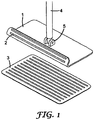
- Fig. 1 is a perspective view of the first embodiment of the cleaning device having multiple cleaning surfaces according to the present invention.
- the cleaning device has a cleaning portion, a supporting arm 4 and a pivoting mechanism 5.
- the cleaning portion has a cleaning surface on its bottom surface, and an opposite surface opposed to the cleaning surface on its top surface.
- the support arm 4 is pivotably supported on the opposite surface by means of the pivoting mechanism 5 mounted on the opposite surface, so as to freely rotate with respect to the cleaning portion.
- the cleaning surface of the cleaning portion includes a first cleaning material surface 3a and a second cleaning material surface 3b.
- the cleaning portion has a supporting plate 1.
- the first cleaning material surface 3a is disposed on the bottom surface of the supporting plate 1
- the second cleaning material surface 3b is disposed on the side surface of the supporting plate 1. It can be seen from Fig. 1 that the first cleaning material surface 3a is disposed on a cleaning plate whose dimension is substantially identical to that of the bottom surface of the supporting plate 1, then is mounted to the bottom surface of the supporting plate 1.
- the second cleaning material surface 3b is directly disposed on the side surface of the supporting plate 1.
- first cleaning material surface 3a can be directly disposed on the bottom surface of the supporting plate 1, and the second cleaning material surface 3b can be disposed on another cleaning plate and then mounted to the side surface of the supporting plate 1.
- the first cleaning material surface 3a and the second cleaning material surface 3b come into contact with the surfaces to be cleaned, respectively.
- the first cleaning material surface 3a and the second cleaning material surface 3b are designed to form an angle ⁇ larger than 270 degrees. That is, when the first cleaning material surface 3a comes into contact with the surface to be cleaned, the second cleaning material surface 3b has an angle larger than 90 degrees and smaller than 180 degrees with respect to the surface to be cleaned (Refer to Fig. 2A ); when the second cleaning material surface 3b comes into contact with the surface to be cleaned, the first cleaning material surface 3a has an angle larger than 90 degrees and smaller than 180 degrees with respect to the surface to be cleaned (Refer to Fig. 2B ).
- the operator can rotate the support arm 4 during the cleaning work so that the first cleaning material surface 3a and the second cleaning material surface 3b come into contact with the surfaces to be cleaned, respectively.
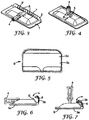
- FIGs. 3 and 4 are the perspective views of an embodiment of a cleaning device having multiple cleaning surfaces according to the present invention, in which the side plate 2 of the cleaning device in Fig. 3 has not been secured onto the supporting plate 1, while the side plate 2 of the cleaning device in Fig. 4 has already been secured onto the supporting plate 1.
- the structures of the second embodiment are substantially identical to those of the first embodiment. Their distinctions mainly lie in that the cleaning portion of the first embodiment is composed of the supporting plate 1, while the cleaning portion of the second embodiment is composed of the supporting plate and at least one side plate 2 pivotably attached to one side of the supporting plate 1.
- the cleaning device has a cleaning portion, a supporting arm 4 and a pivoting mechanism 5.
- the cleaning portion has a cleaning surface on its bottom surface, and an opposite surface opposed to the cleaning surface on its top surface.
- the support arm 4 is pivotably supported on the opposite surface by means of the pivoting mechanism 5 mounted on the opposite surface, so as to freely rotate with respect to the cleaning portion.
- the cleaning portion is composed of a supporting plate 1 and a side plate 2 pivotably attached to one side of the supporting plate 1.
- the cleaning portion can be composed of a supporting plate 1 and at least one side plate 2 pivotably attached to one side of the supporting plate 1.
- both sides of the supporting plate 1 can be equipped with one side plate 2, or every side of the supporting plate 1 can be equipped with one side plate 2.
- the side plate 2 Since the surface area of the side plate 2 is smaller than that of the supporting plate 1, the intensity of pressure applied from the side plate 2 to the surface to be cleaned is larger than that of pressure applied from the supporting plate 1.
- the side plate 2 has an arc shape which is slightly protruded outward as a whole. The radian of the arc is designed to precisely make the side plate 2 come into contact with the surface to be cleaned.
- the cleaning surface of the cleaning portion includes a first cleaning material surface 3a and a second cleaning material surface 3b.
- the first cleaning material surface 3a and the second cleaning material surface 3b are disposed on an integral structure, i.e., a mop cloth 9.
- One end of the mop cloth 9 is secured on the supporting plate 1, and the other end of the mop cloth 9 is secured on to the side plate 2, so that the supporting plate 1 and the side plate 2 are wrapped therein.
- Fig. 5 it is a plan view of the mop cloth 9.
- the mop cloth 9 has a rectangle shape.
- a plurality of pockets 3a may be sewn on the mop cloth 9.
- the corner portions of mop cloth 9 are tailored to conform to the shapes of supporting plate 1 and side plate 2, so that the mop cloth 9 is firmly fixed on the supporting plate 1 and the side plate 2.
- the first cleaning material surface 3a is disposed on the position where corresponds to the supporting plate 1 on the mop cloth 9 and covers the bottom surface of the supporting plate 1
- the second cleaning material surface 3b is disposed on the position where corresponds to the side plate 2 on the mop cloth 9 and covers the bottom surface of the side plate 2. Since the surface area of the supporting plate 2 is larger than that of the side plate 1, the surface area of the first cleaning material surface 3a is also larger than that of the second cleaning material surface 3b.
- the cleaning materials of the first cleaning material surface 3a and the second cleaning material surface 3b can be the same or different.
- the cleaning material of the first cleaning material surface 3a is a conventional cleaning material
- the cleaning material of the second cleaning material surface 3b is an abrasive material or a bibulous material.
- the conventional cleaning material includes cotton thread, polyester fiber, superfine fiber, non-woven fabrics, etc.
- the abrasive material includes nylon non-woven fabrics or nylon fabrics having abrasive particles, etc.
- the bibulous material includes superfine fiber, PVC, wood pulp sponge, etc.
- the supporting plate 1 has an inclined surface 6 on the side adjacent to the side plate 2.
- the lower portion of the inclined surface 6 is equipped with a pivot shaft, the side plate 2 can freely rotate about the lower portion of the inclined surface via the pivot shaft.
- its distal edge i.e., a movable edge which can free rotate with respect to the supporting plate 1
- the side plate 2 and the supporting plate 1 forms an angle ⁇ larger than 270 degrees.
- Two protrusion portions 7 are integrally formed on the distal edge of the side plate 2, and a plurality of positioning teeth 8 (It has five positioning teeth in the present embodiment) are disposed on each protrusion portion 7.
- a low of position cooperation teeth 8' are disposed on the top of the inclined surface 6 of the supporting plate 1, as seen in Fig. 3 , the position cooperation teeth 8' are disposed on both sides of the supporting plate 1 along its central axis, and four teeth are formed on each side, but their positions are overlapped with the row of the positioning teeth 8 on the side plate 2. Therefore, after the distal edge of the side plate 2 is abutted against the top of the inclined surface 6, the positioning teeth 8 of the side plate 2 and the position cooperation teeth 8' of the supporting plate 1 can be firmly secured together if a slight force is applied.
- fastening means such as, a fastening ring, a buckle or a plug, etc.
- a fastening ring such as, a buckle or a plug, etc.
- the side surface 2 and the supporting surface 1 form an angle ⁇ larger than 270 degrees.
- the above-mentioned fastening means shall also fall within the scope for which protection is sought in the present invention.
- the user can make use of the supporting plate 1 with larger contact area and less cleaning pressure when cleaning ordinary floor.
- the user can make use of the side plate 2 with less contact area and larger cleaning pressure when cleaning particular floor having stubborn stains, so that the force exerted by user is effectively transmitted to the floor, whereby stubborn stains are removed.
- the cleaning device of the present invention can enter into a narrow space for its cleaning work. Since the mop cloth 9 wraps the edges of the supporting plate 1, the objects to be cleaned will not be injured or scraped by impact of the cleaning device when cleaning wall corners or furniture legs in the cleaning sites.
- the user first covers the mop cloth 9 with the supporting plate 1 and the side plate 2, and then pivots the side plate 2 anticlockwise.
- the side plate 2 is rotated to a position where its distal edge is just abutted against the top of the inclined surface 6, a force is applied to the side plate 2 so that the positioning teeth 8 are snap-fitted into the cooperation teeth 8' of the supporting plate 1.
- the mop cloth 9 is firmly held between the two rows of teeth 8, 8'.
- the user can make use of the supporting plate 1 when cleaning ordinary floor; and if a floor with stubborn stains or a narrow floor space shall be cleaned, the user can rotate the supporting arm 4, swing the supporting plate 1 upward and make the side plate 2 come into contact with the surface to be cleaned, so that the supporting plate 1 is replaced with the side plate 2 for cleaning the surface to be cleaned.
- first cleaning material surface and the second cleaning material surface can be integrally or separately replaceable; the shape of the first cleaning material surface can be different from that of the second cleaning material surface; and the number of the positioning teeth and the cooperation teeth can be varied, etc. All these modifications will fall within the scope of Claims appended in present invention.
Landscapes
- Cleaning Implements For Floors, Carpets, Furniture, Walls, And The Like (AREA)
Claims (10)
- Reinigungsvorrichtung, umfassend:einen Reinigungsabschnitt, der mit einer Reinigungsfläche und einer gegenüberliegenden Fläche gegenüber der Reinigungsfläche versehen ist,einen Stützarm (4); undeinen Schwenkmechanismus (5) zum schwenkbaren Stützen des Stützarms (4) an der gegenüberliegenden Fläche,wobei die Reinigungsfläche des Reinigungsabschnitts eine erste Reinigungsmaterialfläche (3a) und eine zweite Reinigungsmaterialfläche (3b) aufweist, wobei die erste Reinigungsmaterialfläche (3 a) und die zweite Reinigungsmaterialfläche (3b) jeweils mit den zu reinigenden Flächen in Kontakt kommen,dadurch gekennzeichnet, dassder Reinigungsabschnitt mit einer Stützplatte (1), mindestens einer Seitenplatte (2), die schwenkbar an einer Seite der Stützplatte angebracht ist, und Befestigungsmitteln versehen ist, um einen beweglichen distalen Rand der Seitenplatte gezielt an der Stützplatte in einer befestigten Position der Seitenplatte bezüglich der Stützplatte zu befestigen,in der befestigten Position, wenn eine beliebige der ersten Reinigungsmaterialfläche (3a) und der zweiten Reinigungsmaterialfläche (3b) mit der zu reinigenden Fläche in Kontakt kommt, die jeweils andere Reinigungsmaterialfläche einen Winkel von 90 Grad bis 180 Grad zu der zu reinigenden Fläche einnimmt.
- Reinigungsvorrichtung nach Ansprach 1, wobei
die erste Reinigungsmaterialfläche (3a) auf der unteren Fläche der Stützplatte (1) an geordnet ist und die zweite Reinigungsmaterialfläche (3b) auf der unteren Fläche der Seitenplatte (2) angeordnet ist. - Reinigungsvorrichtung nach Anspruch 1, wobei
die Seitenplatte (2) an dem beweglichen Rand mit Positionierungselementen (8) versehen ist und die Stützplatte (1) mit Positionszusammenwirkungsmitteln (8') zum Zusammenpassen mit den Positionierungselementen (8) versehen ist, wobei die Seitenplatte (2) und die Stützplatte (1) nach der Befestigung der Positionierungselemente (8) und der Positionszusammenwirkungsmittel (8') einen Winkel (ß) bilden, der größer als 270 Grad ist, und die erste Reinigungsmaterialfläche (3a) und die zweite Reinigungsmaterialfläche (3b) auf der unteren Fläche der Stützplatte (1) bzw. der Seitenfläche der Seitenplatte (2) angeordnet sind. - Reinigungsvorrichtung nach Anspruch 3, wobei
sowohl die Positionierungselemente (8) als auch die Positionszusammenwirkungsmittel (8') aus einer Reihe Zähne bestehen, deren Positionen sich mit der anderen Reihe überlappen, um in der befestigten Position eine eingerastete Anordnung bereitzustellen. - Reinigungsvorrichtung nach Anspruch 3,
wobei die erste Reinigungsmaterialfläche (3a) und die zweite Reinigungsmaterialfläche (3b) auf einer integralen Struktur (9) angeordnet sind und mittels der integralen Struktur, der Positionierungselemente (8) und der Positionszusammenwirkungsmittel (8') an vorbestimmten Positionen der Stützplatte (1) und der Seitenplatte (2) befestigt sind. - Reinigungsvorrichtung nach Anspruch 2 oder 3, wobei
die erste Reinigungsmaterialfläche (3a) und die zweite Reinigungsmaterialfläche (3b) ersetzbar sind. - Reinigungsvorrichtung nach Anspruch 2 oder 3, wobei
die erste Reinigungsmaterialfläche (3a) und die zweite Reinigungsmaterialfläche (3b) getrennt ersetzbar sind. - Reinigungsvorrichtung nach Anspruch 2 oder 3, wobei
das Reinigungsmaterial der ersten Reinigungsmaterialfläche (3a) mit dem der zweiten Reinigungsmaterialfläche (3b) identisch ist. - Reinigungsvorrichtung nach Anspruch 2 oder 3, wobei
sich das Reinigungsmaterial der ersten Reinigungsmaterialfläche (3a) von dem der zweiten Reinigungsmaterialfläche (3b) unterscheidet. - Reinigungsvorrichtung nach Anspruch 9, wobei
das Reinigungsmaterial der ersten Reinigungsmaterialfläche (3a) ein herkömmliches Reinigungsmaterial ist und das Reinigungsmaterial der zweiten Reinigungsmaterialfläche (3b) ein Scheuermaterial ist.
Applications Claiming Priority (2)
| Application Number | Priority Date | Filing Date | Title |
|---|---|---|---|
| CN2006100733741A CN101044967B (zh) | 2006-03-31 | 2006-03-31 | 具有多清洁面的清洁装置 |
| PCT/US2007/065314 WO2007115026A2 (en) | 2006-03-31 | 2007-03-28 | A cleaning device having multiple cleaning surfaces |
Publications (4)
| Publication Number | Publication Date |
|---|---|
| EP2007267A2 EP2007267A2 (de) | 2008-12-31 |
| EP2007267A4 EP2007267A4 (de) | 2011-04-06 |
| EP2007267B1 EP2007267B1 (de) | 2014-07-09 |
| EP2007267B2 true EP2007267B2 (de) | 2018-06-06 |
Family
ID=38564181
Family Applications (1)
| Application Number | Title | Priority Date | Filing Date |
|---|---|---|---|
| EP07759533.8A Not-in-force EP2007267B2 (de) | 2006-03-31 | 2007-03-28 | Reinigungsvorrichtung mit mehreren reinigungsoberflächen |
Country Status (8)
| Country | Link |
|---|---|
| US (1) | US8464389B2 (de) |
| EP (1) | EP2007267B2 (de) |
| JP (1) | JP5284945B2 (de) |
| KR (1) | KR101283136B1 (de) |
| CN (1) | CN101044967B (de) |
| BR (1) | BRPI0709437A2 (de) |
| MX (1) | MX2008012470A (de) |
| WO (1) | WO2007115026A2 (de) |
Families Citing this family (20)
| Publication number | Priority date | Publication date | Assignee | Title |
|---|---|---|---|---|
| US7841040B2 (en) * | 2006-09-26 | 2010-11-30 | First Quality Retail Services, Llc | Absorbent cleaning pad with extended portion for use with a cleaning implement |
| US8671500B2 (en) * | 2008-04-11 | 2014-03-18 | Ecolab USA, Inc. | Grill tool, associated pad, and associated methods |
| US9049792B2 (en) * | 2011-12-26 | 2015-06-02 | Samsung Electronics Co., Ltd. | Protection cover and portable apparatus having the same |
| JP5799405B2 (ja) * | 2012-12-28 | 2015-10-28 | 池田 章志郎 | フローリングワイパーヘッド |
| US9155440B2 (en) | 2013-03-15 | 2015-10-13 | Electrolux Home Care Products, Inc. | Steam distribution apparatus and methods for steam cleaning devices |
| US9743819B2 (en) | 2013-09-24 | 2017-08-29 | Midea America, Corp. | Floor mop with concentrated cleaning feature |
| US9554686B2 (en) | 2013-09-24 | 2017-01-31 | Electrolux Home Care Products, Inc. | Flexible scrubbing head for a floor mop |
| FR3010889B1 (fr) * | 2013-09-25 | 2015-09-25 | Concept Microfibre | Dispositif comprenant une tete de nettoyage et un systeme de basculement entre deux surfaces. |
| US9179815B2 (en) | 2013-10-01 | 2015-11-10 | Electrolux Home Care Products, Inc. | Floor mop with removable base plate |
| JP6644467B2 (ja) * | 2014-12-26 | 2020-02-12 | 株式会社吉野工業所 | 清掃用具 |
| EP3592915B1 (de) * | 2017-03-08 | 2022-01-05 | Husqvarna AB | Rinnenreiniger |
| JP7034607B2 (ja) * | 2017-05-31 | 2022-03-14 | レック株式会社 | 清掃具 |
| DE202018003235U1 (de) * | 2018-07-05 | 2018-09-03 | Frank Gladosch | Mikrofaser-Bodenwischtuch für Klapphalter |
| WO2020023858A1 (en) * | 2018-07-26 | 2020-01-30 | Micronova Manufacturing, Inc. | Wall cleaning tool |
| JP7018867B2 (ja) * | 2018-11-09 | 2022-02-14 | ユニ・チャーム株式会社 | 清掃具用の清掃ヘッド、上記清掃ヘッドを備える清掃具、清掃シートの、上記清掃具への使用、及び上記清掃具用の清掃シート |
| USD927198S1 (en) | 2018-11-27 | 2021-08-10 | Unger Marketing International, Llc | Brush handle |
| USD939801S1 (en) | 2018-11-27 | 2021-12-28 | Unger Marketing International, Llc | Brush handle |
| US11304583B2 (en) * | 2019-07-15 | 2022-04-19 | Lynda Lee Whittington | Joist and baseboard apparatus |
| CN113907655A (zh) * | 2020-07-07 | 2022-01-11 | 宁波方太厨具有限公司 | 一种拖地清洁机器人及其工作控制方法 |
| CN112587053B (zh) * | 2020-12-25 | 2025-09-23 | 台州本上日用品有限公司 | 一种可折叠拖把头 |
Citations (9)
| Publication number | Priority date | Publication date | Assignee | Title |
|---|---|---|---|---|
| EP0269852A1 (de) † | 1986-11-22 | 1988-06-08 | CORONET-WERKE Heinrich Schlerf GmbH | Stielbesen |
| US4845800A (en) † | 1988-06-15 | 1989-07-11 | Pederson Darrell L | Folding mop |
| WO1995032661A1 (en) † | 1994-05-31 | 1995-12-07 | Minnesota Mining And Manufacturing Company | Floor mop and cleaning system |
| DE29605019U1 (de) † | 1996-03-19 | 1996-05-23 | Fürstenberg, Friedhelm, 22111 Hamburg | Reinigungsgerät |
| US5864914A (en) † | 1995-08-08 | 1999-02-02 | Vermop Salmon Gmbh | Mop holder with an elongated frame for accommodating a mop cover |
| US20020120996A1 (en) † | 2001-02-09 | 2002-09-05 | Bruce Kaminstein | Flexible mop base |
| US20020174502A1 (en) † | 2001-04-02 | 2002-11-28 | Kathryn Cioci | Sponge mop with flexible ends |
| WO2006002653A1 (en) † | 2004-06-29 | 2006-01-12 | Ecolab Inc. | Mopping device for mopping surfaces to be cleaned, mop holder and mop cover for a mopping device |
| WO2006002654A1 (en) † | 2004-06-29 | 2006-01-12 | Ecolab Inc. | Mop holder for mounting a mop cover |
Family Cites Families (32)
| Publication number | Priority date | Publication date | Assignee | Title |
|---|---|---|---|---|
| US3656202A (en) | 1970-02-03 | 1972-04-18 | Schlegel Mfg Co | Combined sponge, scouring pile material and squeegee cleaning implement |
| US4114223A (en) | 1977-05-09 | 1978-09-19 | Ritchie Buchanan | Mop having a removable cover |
| CA1099862A (en) | 1980-02-11 | 1981-04-28 | Albert N. Thompson | Curling push-broom |
| GB2233882B (en) | 1989-07-04 | 1993-02-10 | Fatma Meissner | Cleaning apparatus and method |
| JPH0610937Y2 (ja) * | 1990-02-05 | 1994-03-23 | 株式会社テラモト | モップ |
| US5280664A (en) | 1992-03-20 | 1994-01-25 | Lin Mary D | Disposable household cleaning devices |
| JPH08522A (ja) * | 1994-06-15 | 1996-01-09 | Azuma Kogyo Kk | モップ |
| US5596787A (en) | 1995-08-08 | 1997-01-28 | Stevens; Elwood L. | Wiping device for interior surfaces of vehicle windshield glass |
| JP3660419B2 (ja) | 1995-10-23 | 2005-06-15 | 株式会社ニトムズ | 清掃布 |
| JP3515261B2 (ja) | 1995-12-15 | 2004-04-05 | 株式会社ニトムズ | 清掃布 |
| JPH10286208A (ja) * | 1997-04-16 | 1998-10-27 | Lion Corp | 形状変更可能なモップ |
| JPH10290770A (ja) | 1997-04-17 | 1998-11-04 | Lion Corp | 掃除具 |
| JP3544108B2 (ja) | 1997-10-29 | 2004-07-21 | ユニ・チャーム株式会社 | 清掃用シート |
| JP3544109B2 (ja) | 1997-11-07 | 2004-07-21 | ユニ・チャーム株式会社 | 粘弾性の粘着材を利用した清掃用シート |
| AU1816200A (en) | 1998-11-09 | 2000-05-29 | Procter & Gamble Company, The | Cleaning composition, pad, wipe, implement, and system and method of use thereof |
| US7144173B2 (en) | 1998-11-09 | 2006-12-05 | The Procter & Gamble Company | Cleaning composition, pad, wipe, implement, and system and method of use thereof |
| JP2002165740A (ja) | 2000-11-30 | 2002-06-11 | Three M Innovative Properties Co | 清掃用具 |
| US7047586B2 (en) | 2000-11-30 | 2006-05-23 | 3M Innovative Properties Company | Cleaning device with a cleaning portion comprising an adhesive surface and a cleaning cloth surface |
| JP2002238824A (ja) | 2001-02-22 | 2002-08-27 | Azuma Industrial Co Ltd | モップ付き塵取り |
| EP1238621A1 (de) * | 2001-03-09 | 2002-09-11 | 3M Innovative Properties Company | Doppelseitiges Reinigungsgerät |
| CN2549888Y (zh) | 2002-05-17 | 2003-05-14 | 张文巨 | 双面拖把 |
| US20040019995A1 (en) * | 2002-07-31 | 2004-02-05 | Bluebonnet Industrial Brush Company, Inc. | Scuff mark removal tool for floors |
| CN2572917Y (zh) | 2002-09-27 | 2003-09-17 | 虞建军 | 新型节能拖把 |
| JP2004201716A (ja) | 2002-12-20 | 2004-07-22 | Fuji Enterp:Kk | 清掃器具 |
| TW588639U (en) | 2003-02-14 | 2004-05-21 | Jia-Yi Sie | Mop and connectors |
| MXPA05009657A (es) | 2003-03-11 | 2005-10-20 | Procter & Gamble | Implemento de limpieza. |
| JP4266009B2 (ja) | 2003-04-04 | 2009-05-20 | スン ジェ リー | 両面使用可能なフロアモップ |
| SE524846C2 (sv) * | 2003-05-02 | 2004-10-12 | Smart Products Scandinavia Ab | Moppstativ för bl a en golvmopp samt mopp för rengöring av bl a golv |
| DE10337102A1 (de) | 2003-08-11 | 2005-03-10 | Ecolab Inc | Wischvorrichtung und Wischbezug |
| US7591040B2 (en) * | 2003-12-18 | 2009-09-22 | Kimberly-Clark Worldwide, Inc. | Cleaning tool for removing larger and smaller sized particles |
| CN2678552Y (zh) | 2004-02-11 | 2005-02-16 | 上海镁嘉实业有限公司 | 一种可翻面的拖把 |
| FR2896411B1 (fr) | 2006-01-20 | 2009-08-07 | Oreal | Composition cosmetique non-lavante comprenant un polymere fixant ionique et un ester de polyethyleneglycol et d'acides gras, procede de fixation de la coiffure et utilisations |
-
2006
- 2006-03-31 CN CN2006100733741A patent/CN101044967B/zh not_active Expired - Lifetime
-
2007
- 2007-03-28 WO PCT/US2007/065314 patent/WO2007115026A2/en not_active Ceased
- 2007-03-28 EP EP07759533.8A patent/EP2007267B2/de not_active Not-in-force
- 2007-03-28 MX MX2008012470A patent/MX2008012470A/es active IP Right Grant
- 2007-03-28 KR KR1020087024573A patent/KR101283136B1/ko not_active Expired - Fee Related
- 2007-03-28 JP JP2009503231A patent/JP5284945B2/ja active Active
- 2007-03-28 US US12/294,440 patent/US8464389B2/en active Active
- 2007-03-28 BR BRPI0709437-0A patent/BRPI0709437A2/pt not_active IP Right Cessation
Patent Citations (9)
| Publication number | Priority date | Publication date | Assignee | Title |
|---|---|---|---|---|
| EP0269852A1 (de) † | 1986-11-22 | 1988-06-08 | CORONET-WERKE Heinrich Schlerf GmbH | Stielbesen |
| US4845800A (en) † | 1988-06-15 | 1989-07-11 | Pederson Darrell L | Folding mop |
| WO1995032661A1 (en) † | 1994-05-31 | 1995-12-07 | Minnesota Mining And Manufacturing Company | Floor mop and cleaning system |
| US5864914A (en) † | 1995-08-08 | 1999-02-02 | Vermop Salmon Gmbh | Mop holder with an elongated frame for accommodating a mop cover |
| DE29605019U1 (de) † | 1996-03-19 | 1996-05-23 | Fürstenberg, Friedhelm, 22111 Hamburg | Reinigungsgerät |
| US20020120996A1 (en) † | 2001-02-09 | 2002-09-05 | Bruce Kaminstein | Flexible mop base |
| US20020174502A1 (en) † | 2001-04-02 | 2002-11-28 | Kathryn Cioci | Sponge mop with flexible ends |
| WO2006002653A1 (en) † | 2004-06-29 | 2006-01-12 | Ecolab Inc. | Mopping device for mopping surfaces to be cleaned, mop holder and mop cover for a mopping device |
| WO2006002654A1 (en) † | 2004-06-29 | 2006-01-12 | Ecolab Inc. | Mop holder for mounting a mop cover |
Also Published As
| Publication number | Publication date |
|---|---|
| KR101283136B1 (ko) | 2013-07-05 |
| EP2007267A2 (de) | 2008-12-31 |
| CN101044967B (zh) | 2010-12-15 |
| EP2007267A4 (de) | 2011-04-06 |
| WO2007115026A3 (en) | 2007-11-22 |
| EP2007267B1 (de) | 2014-07-09 |
| KR20080104361A (ko) | 2008-12-02 |
| WO2007115026A2 (en) | 2007-10-11 |
| MX2008012470A (es) | 2008-10-10 |
| US8464389B2 (en) | 2013-06-18 |
| JP5284945B2 (ja) | 2013-09-11 |
| US20100293732A1 (en) | 2010-11-25 |
| JP2009532114A (ja) | 2009-09-10 |
| BRPI0709437A2 (pt) | 2011-07-05 |
| CN101044967A (zh) | 2007-10-03 |
Similar Documents
| Publication | Publication Date | Title |
|---|---|---|
| EP2007267B2 (de) | Reinigungsvorrichtung mit mehreren reinigungsoberflächen | |
| CA2841726C (en) | Multi-surfaces cleaning implement | |
| US20050011536A1 (en) | Cleaning implement | |
| EP1486156A2 (de) | Elektrischer Staubsauger umfassend eine ein entfernbares Wischtuch aufweisende Saugdüse | |
| CA2280164C (en) | Absorbent broom cover | |
| KR101629924B1 (ko) | 청소용 밀대에 착탈되는 걸레포 | |
| KR101063016B1 (ko) | 밀걸레 청소도구용 걸레 틀 | |
| JP2007044088A (ja) | ハンディモップ | |
| KR100883551B1 (ko) | 청소용 밀대걸레 | |
| JP3448224B2 (ja) | 払拭清掃具 | |
| KR20230042427A (ko) | 회전형 밀대 청소기 | |
| KR200424529Y1 (ko) | 밀걸레 | |
| JPH08322779A (ja) | 柄付きモップ | |
| CA2751193A1 (en) | Multi-surfaces cleaning implement | |
| CN220986126U (zh) | 一种带有双向卡接拖把的清洁工具 | |
| KR200428061Y1 (ko) | 빗자루 겸용 물걸레 청소구 | |
| JP2005152334A (ja) | ハンディモップ | |
| JPH09313415A (ja) | 清掃具 | |
| JP7499650B2 (ja) | 全周モップ | |
| KR100714967B1 (ko) | 다기능 손걸레 | |
| KR200399272Y1 (ko) | 다기능 손걸레 | |
| JP2007021058A (ja) | 吸込具及びそれを用いた電気掃除機 | |
| KR20250039011A (ko) | 유연성있는 베이스판을 가진 밀대 | |
| WO2004002285A1 (en) | Surface working apparatus | |
| JP2003102665A (ja) | 回転モップ |
Legal Events
| Date | Code | Title | Description |
|---|---|---|---|
| PUAI | Public reference made under article 153(3) epc to a published international application that has entered the european phase |
Free format text: ORIGINAL CODE: 0009012 |
|
| 17P | Request for examination filed |
Effective date: 20081024 |
|
| AK | Designated contracting states |
Kind code of ref document: A2 Designated state(s): AT BE BG CH CY CZ DE DK EE ES FI FR GB GR HU IE IS IT LI LT LU LV MC MT NL PL PT RO SE SI SK TR |
|
| AX | Request for extension of the european patent |
Extension state: AL BA HR MK RS |
|
| A4 | Supplementary search report drawn up and despatched |
Effective date: 20110308 |
|
| RIC1 | Information provided on ipc code assigned before grant |
Ipc: A47L 13/12 20060101ALI20110302BHEP Ipc: A47L 13/24 20060101AFI20081029BHEP Ipc: A47L 13/256 20060101ALI20110302BHEP Ipc: A47L 13/254 20060101ALI20110302BHEP |
|
| DAX | Request for extension of the european patent (deleted) | ||
| 17Q | First examination report despatched |
Effective date: 20130104 |
|
| GRAP | Despatch of communication of intention to grant a patent |
Free format text: ORIGINAL CODE: EPIDOSNIGR1 |
|
| INTG | Intention to grant announced |
Effective date: 20131211 |
|
| GRAJ | Information related to disapproval of communication of intention to grant by the applicant or resumption of examination proceedings by the epo deleted |
Free format text: ORIGINAL CODE: EPIDOSDIGR1 |
|
| GRAP | Despatch of communication of intention to grant a patent |
Free format text: ORIGINAL CODE: EPIDOSNIGR1 |
|
| INTG | Intention to grant announced |
Effective date: 20140502 |
|
| GRAS | Grant fee paid |
Free format text: ORIGINAL CODE: EPIDOSNIGR3 |
|
| GRAA | (expected) grant |
Free format text: ORIGINAL CODE: 0009210 |
|
| AK | Designated contracting states |
Kind code of ref document: B1 Designated state(s): AT BE BG CH CY CZ DE DK EE ES FI FR GB GR HU IE IS IT LI LT LU LV MC MT NL PL PT RO SE SI SK TR |
|
| REG | Reference to a national code |
Ref country code: GB Ref legal event code: FG4D |
|
| REG | Reference to a national code |
Ref country code: CH Ref legal event code: EP Ref country code: AT Ref legal event code: REF Ref document number: 676258 Country of ref document: AT Kind code of ref document: T Effective date: 20140715 |
|
| REG | Reference to a national code |
Ref country code: IE Ref legal event code: FG4D |
|
| REG | Reference to a national code |
Ref country code: DE Ref legal event code: R096 Ref document number: 602007037561 Country of ref document: DE Effective date: 20140821 |
|
| REG | Reference to a national code |
Ref country code: AT Ref legal event code: MK05 Ref document number: 676258 Country of ref document: AT Kind code of ref document: T Effective date: 20140709 |
|
| REG | Reference to a national code |
Ref country code: NL Ref legal event code: VDEP Effective date: 20140709 |
|
| REG | Reference to a national code |
Ref country code: LT Ref legal event code: MG4D |
|
| PG25 | Lapsed in a contracting state [announced via postgrant information from national office to epo] |
Ref country code: SE Free format text: LAPSE BECAUSE OF FAILURE TO SUBMIT A TRANSLATION OF THE DESCRIPTION OR TO PAY THE FEE WITHIN THE PRESCRIBED TIME-LIMIT Effective date: 20140709 Ref country code: ES Free format text: LAPSE BECAUSE OF FAILURE TO SUBMIT A TRANSLATION OF THE DESCRIPTION OR TO PAY THE FEE WITHIN THE PRESCRIBED TIME-LIMIT Effective date: 20140709 Ref country code: PT Free format text: LAPSE BECAUSE OF FAILURE TO SUBMIT A TRANSLATION OF THE DESCRIPTION OR TO PAY THE FEE WITHIN THE PRESCRIBED TIME-LIMIT Effective date: 20141110 Ref country code: LT Free format text: LAPSE BECAUSE OF FAILURE TO SUBMIT A TRANSLATION OF THE DESCRIPTION OR TO PAY THE FEE WITHIN THE PRESCRIBED TIME-LIMIT Effective date: 20140709 Ref country code: FI Free format text: LAPSE BECAUSE OF FAILURE TO SUBMIT A TRANSLATION OF THE DESCRIPTION OR TO PAY THE FEE WITHIN THE PRESCRIBED TIME-LIMIT Effective date: 20140709 Ref country code: BG Free format text: LAPSE BECAUSE OF FAILURE TO SUBMIT A TRANSLATION OF THE DESCRIPTION OR TO PAY THE FEE WITHIN THE PRESCRIBED TIME-LIMIT Effective date: 20141009 Ref country code: GR Free format text: LAPSE BECAUSE OF FAILURE TO SUBMIT A TRANSLATION OF THE DESCRIPTION OR TO PAY THE FEE WITHIN THE PRESCRIBED TIME-LIMIT Effective date: 20141010 |
|
| PG25 | Lapsed in a contracting state [announced via postgrant information from national office to epo] |
Ref country code: LV Free format text: LAPSE BECAUSE OF FAILURE TO SUBMIT A TRANSLATION OF THE DESCRIPTION OR TO PAY THE FEE WITHIN THE PRESCRIBED TIME-LIMIT Effective date: 20140709 Ref country code: NL Free format text: LAPSE BECAUSE OF FAILURE TO SUBMIT A TRANSLATION OF THE DESCRIPTION OR TO PAY THE FEE WITHIN THE PRESCRIBED TIME-LIMIT Effective date: 20140709 Ref country code: PL Free format text: LAPSE BECAUSE OF FAILURE TO SUBMIT A TRANSLATION OF THE DESCRIPTION OR TO PAY THE FEE WITHIN THE PRESCRIBED TIME-LIMIT Effective date: 20140709 Ref country code: CY Free format text: LAPSE BECAUSE OF FAILURE TO SUBMIT A TRANSLATION OF THE DESCRIPTION OR TO PAY THE FEE WITHIN THE PRESCRIBED TIME-LIMIT Effective date: 20140709 Ref country code: IS Free format text: LAPSE BECAUSE OF FAILURE TO SUBMIT A TRANSLATION OF THE DESCRIPTION OR TO PAY THE FEE WITHIN THE PRESCRIBED TIME-LIMIT Effective date: 20141109 Ref country code: AT Free format text: LAPSE BECAUSE OF FAILURE TO SUBMIT A TRANSLATION OF THE DESCRIPTION OR TO PAY THE FEE WITHIN THE PRESCRIBED TIME-LIMIT Effective date: 20140709 |
|
| REG | Reference to a national code |
Ref country code: DE Ref legal event code: R026 Ref document number: 602007037561 Country of ref document: DE |
|
| PLBI | Opposition filed |
Free format text: ORIGINAL CODE: 0009260 |
|
| PG25 | Lapsed in a contracting state [announced via postgrant information from national office to epo] |
Ref country code: RO Free format text: LAPSE BECAUSE OF FAILURE TO SUBMIT A TRANSLATION OF THE DESCRIPTION OR TO PAY THE FEE WITHIN THE PRESCRIBED TIME-LIMIT Effective date: 20140709 Ref country code: SK Free format text: LAPSE BECAUSE OF FAILURE TO SUBMIT A TRANSLATION OF THE DESCRIPTION OR TO PAY THE FEE WITHIN THE PRESCRIBED TIME-LIMIT Effective date: 20140709 Ref country code: DK Free format text: LAPSE BECAUSE OF FAILURE TO SUBMIT A TRANSLATION OF THE DESCRIPTION OR TO PAY THE FEE WITHIN THE PRESCRIBED TIME-LIMIT Effective date: 20140709 Ref country code: IT Free format text: LAPSE BECAUSE OF FAILURE TO SUBMIT A TRANSLATION OF THE DESCRIPTION OR TO PAY THE FEE WITHIN THE PRESCRIBED TIME-LIMIT Effective date: 20140709 Ref country code: EE Free format text: LAPSE BECAUSE OF FAILURE TO SUBMIT A TRANSLATION OF THE DESCRIPTION OR TO PAY THE FEE WITHIN THE PRESCRIBED TIME-LIMIT Effective date: 20140709 Ref country code: CZ Free format text: LAPSE BECAUSE OF FAILURE TO SUBMIT A TRANSLATION OF THE DESCRIPTION OR TO PAY THE FEE WITHIN THE PRESCRIBED TIME-LIMIT Effective date: 20140709 |
|
| 26 | Opposition filed |
Opponent name: LEIFHEIT AG Effective date: 20150408 |
|
| PLAX | Notice of opposition and request to file observation + time limit sent |
Free format text: ORIGINAL CODE: EPIDOSNOBS2 |
|
| REG | Reference to a national code |
Ref country code: DE Ref legal event code: R026 Ref document number: 602007037561 Country of ref document: DE Effective date: 20150408 |
|
| PLAF | Information modified related to communication of a notice of opposition and request to file observations + time limit |
Free format text: ORIGINAL CODE: EPIDOSCOBS2 |
|
| PG25 | Lapsed in a contracting state [announced via postgrant information from national office to epo] |
Ref country code: MC Free format text: LAPSE BECAUSE OF FAILURE TO SUBMIT A TRANSLATION OF THE DESCRIPTION OR TO PAY THE FEE WITHIN THE PRESCRIBED TIME-LIMIT Effective date: 20140709 Ref country code: LU Free format text: LAPSE BECAUSE OF FAILURE TO SUBMIT A TRANSLATION OF THE DESCRIPTION OR TO PAY THE FEE WITHIN THE PRESCRIBED TIME-LIMIT Effective date: 20150328 |
|
| REG | Reference to a national code |
Ref country code: CH Ref legal event code: PL |
|
| GBPC | Gb: european patent ceased through non-payment of renewal fee |
Effective date: 20150328 |
|
| PG25 | Lapsed in a contracting state [announced via postgrant information from national office to epo] |
Ref country code: SI Free format text: LAPSE BECAUSE OF FAILURE TO SUBMIT A TRANSLATION OF THE DESCRIPTION OR TO PAY THE FEE WITHIN THE PRESCRIBED TIME-LIMIT Effective date: 20140709 |
|
| PLBB | Reply of patent proprietor to notice(s) of opposition received |
Free format text: ORIGINAL CODE: EPIDOSNOBS3 |
|
| REG | Reference to a national code |
Ref country code: FR Ref legal event code: ST Effective date: 20151130 |
|
| REG | Reference to a national code |
Ref country code: IE Ref legal event code: MM4A |
|
| PG25 | Lapsed in a contracting state [announced via postgrant information from national office to epo] |
Ref country code: IE Free format text: LAPSE BECAUSE OF NON-PAYMENT OF DUE FEES Effective date: 20150328 Ref country code: LI Free format text: LAPSE BECAUSE OF NON-PAYMENT OF DUE FEES Effective date: 20150331 Ref country code: CH Free format text: LAPSE BECAUSE OF NON-PAYMENT OF DUE FEES Effective date: 20150331 Ref country code: GB Free format text: LAPSE BECAUSE OF NON-PAYMENT OF DUE FEES Effective date: 20150328 |
|
| PG25 | Lapsed in a contracting state [announced via postgrant information from national office to epo] |
Ref country code: FR Free format text: LAPSE BECAUSE OF NON-PAYMENT OF DUE FEES Effective date: 20150331 |
|
| PG25 | Lapsed in a contracting state [announced via postgrant information from national office to epo] |
Ref country code: BE Free format text: LAPSE BECAUSE OF FAILURE TO SUBMIT A TRANSLATION OF THE DESCRIPTION OR TO PAY THE FEE WITHIN THE PRESCRIBED TIME-LIMIT Effective date: 20140709 |
|
| PG25 | Lapsed in a contracting state [announced via postgrant information from national office to epo] |
Ref country code: MT Free format text: LAPSE BECAUSE OF FAILURE TO SUBMIT A TRANSLATION OF THE DESCRIPTION OR TO PAY THE FEE WITHIN THE PRESCRIBED TIME-LIMIT Effective date: 20140709 |
|
| PG25 | Lapsed in a contracting state [announced via postgrant information from national office to epo] |
Ref country code: HU Free format text: LAPSE BECAUSE OF FAILURE TO SUBMIT A TRANSLATION OF THE DESCRIPTION OR TO PAY THE FEE WITHIN THE PRESCRIBED TIME-LIMIT; INVALID AB INITIO Effective date: 20070328 |
|
| PUAH | Patent maintained in amended form |
Free format text: ORIGINAL CODE: 0009272 |
|
| STAA | Information on the status of an ep patent application or granted ep patent |
Free format text: STATUS: PATENT MAINTAINED AS AMENDED |
|
| 27A | Patent maintained in amended form |
Effective date: 20180606 |
|
| AK | Designated contracting states |
Kind code of ref document: B2 Designated state(s): AT BE BG CH CY CZ DE DK EE ES FI FR GB GR HU IE IS IT LI LT LU LV MC MT NL PL PT RO SE SI SK TR |
|
| REG | Reference to a national code |
Ref country code: DE Ref legal event code: R102 Ref document number: 602007037561 Country of ref document: DE |
|
| PGFP | Annual fee paid to national office [announced via postgrant information from national office to epo] |
Ref country code: TR Payment date: 20210324 Year of fee payment: 15 Ref country code: DE Payment date: 20210316 Year of fee payment: 15 |
|
| REG | Reference to a national code |
Ref country code: DE Ref legal event code: R119 Ref document number: 602007037561 Country of ref document: DE |
|
| PG25 | Lapsed in a contracting state [announced via postgrant information from national office to epo] |
Ref country code: DE Free format text: LAPSE BECAUSE OF NON-PAYMENT OF DUE FEES Effective date: 20221001 |
|
| PG25 | Lapsed in a contracting state [announced via postgrant information from national office to epo] |
Ref country code: TR Free format text: LAPSE BECAUSE OF NON-PAYMENT OF DUE FEES Effective date: 20220328 |