EP2000409A2 - Maschine zum füllen eines beutels mit einem arzneimittel - Google Patents
Maschine zum füllen eines beutels mit einem arzneimittel Download PDFInfo
- Publication number
- EP2000409A2 EP2000409A2 EP07737960A EP07737960A EP2000409A2 EP 2000409 A2 EP2000409 A2 EP 2000409A2 EP 07737960 A EP07737960 A EP 07737960A EP 07737960 A EP07737960 A EP 07737960A EP 2000409 A2 EP2000409 A2 EP 2000409A2
- Authority
- EP
- European Patent Office
- Prior art keywords
- medicine
- bag
- medicine bag
- positioning
- belt conveyor
- Prior art date
- Legal status (The legal status is an assumption and is not a legal conclusion. Google has not performed a legal analysis and makes no representation as to the accuracy of the status listed.)
- Withdrawn
Links
- 239000003814 drug Substances 0.000 title claims abstract description 466
- 230000009194 climbing Effects 0.000 claims description 16
- 239000003708 ampul Substances 0.000 description 33
- 229940079593 drug Drugs 0.000 description 31
- 238000010276 construction Methods 0.000 description 20
- 238000003860 storage Methods 0.000 description 13
- 238000003825 pressing Methods 0.000 description 10
- 238000007639 printing Methods 0.000 description 8
- 238000010438 heat treatment Methods 0.000 description 6
- 239000000463 material Substances 0.000 description 5
- 230000000694 effects Effects 0.000 description 3
- 230000005611 electricity Effects 0.000 description 2
- 238000007789 sealing Methods 0.000 description 2
- JOYRKODLDBILNP-UHFFFAOYSA-N Ethyl urethane Chemical compound CCOC(N)=O JOYRKODLDBILNP-UHFFFAOYSA-N 0.000 description 1
- 230000004308 accommodation Effects 0.000 description 1
- 230000001174 ascending effect Effects 0.000 description 1
- 230000033228 biological regulation Effects 0.000 description 1
- 238000004891 communication Methods 0.000 description 1
- 238000005520 cutting process Methods 0.000 description 1
- 238000007689 inspection Methods 0.000 description 1
- 230000014759 maintenance of location Effects 0.000 description 1
- 238000000034 method Methods 0.000 description 1
- 230000000717 retained effect Effects 0.000 description 1
- 238000005096 rolling process Methods 0.000 description 1
- 230000003746 surface roughness Effects 0.000 description 1
- 229920003002 synthetic resin Polymers 0.000 description 1
- 239000000057 synthetic resin Substances 0.000 description 1
Images


Classifications
-
- B—PERFORMING OPERATIONS; TRANSPORTING
- B65—CONVEYING; PACKING; STORING; HANDLING THIN OR FILAMENTARY MATERIAL
- B65B—MACHINES, APPARATUS OR DEVICES FOR, OR METHODS OF, PACKAGING ARTICLES OR MATERIALS; UNPACKING
- B65B5/00—Packaging individual articles in containers or receptacles, e.g. bags, sacks, boxes, cartons, cans, jars
- B65B5/04—Packaging single articles
- B65B5/045—Packaging single articles in bags
-
- B—PERFORMING OPERATIONS; TRANSPORTING
- B65—CONVEYING; PACKING; STORING; HANDLING THIN OR FILAMENTARY MATERIAL
- B65B—MACHINES, APPARATUS OR DEVICES FOR, OR METHODS OF, PACKAGING ARTICLES OR MATERIALS; UNPACKING
- B65B39/00—Nozzles, funnels or guides for introducing articles or materials into containers or wrappers
- B65B39/12—Nozzles, funnels or guides for introducing articles or materials into containers or wrappers movable towards or away from container or wrapper during filling or depositing
-
- B—PERFORMING OPERATIONS; TRANSPORTING
- B65—CONVEYING; PACKING; STORING; HANDLING THIN OR FILAMENTARY MATERIAL
- B65B—MACHINES, APPARATUS OR DEVICES FOR, OR METHODS OF, PACKAGING ARTICLES OR MATERIALS; UNPACKING
- B65B43/00—Forming, feeding, opening or setting-up containers or receptacles in association with packaging
- B65B43/26—Opening or distending bags; Opening, erecting, or setting-up boxes, cartons, or carton blanks
- B65B43/34—Opening or distending bags; Opening, erecting, or setting-up boxes, cartons, or carton blanks by internal pressure
-
- B—PERFORMING OPERATIONS; TRANSPORTING
- B65—CONVEYING; PACKING; STORING; HANDLING THIN OR FILAMENTARY MATERIAL
- B65B—MACHINES, APPARATUS OR DEVICES FOR, OR METHODS OF, PACKAGING ARTICLES OR MATERIALS; UNPACKING
- B65B5/00—Packaging individual articles in containers or receptacles, e.g. bags, sacks, boxes, cartons, cans, jars
- B65B5/06—Packaging groups of articles, the groups being treated as single articles
- B65B5/067—Packaging groups of articles, the groups being treated as single articles in bags
Definitions
- the present invention relates to a machine for filling a bag with medicine in containers liable to suffer damage, such as ampoules.
- the present invention provides a machine for filling a bag with medicine including: a medicine bag positioning member for effecting positioning, with a medicine bag being open; and a bottom surface portion on which medicine to be supplied can be placed, including: a first moving member which reciprocates relative to the medicine bag on which positioning is effected by the medicine bag positioning member and which allows positioning at a supply position inside the medicine bag and a waiting position outside the medicine bag; a second moving member capable of reciprocating relative to the first moving member or the medicine bag and having a guide surface guiding supplied medicine to the bottom surface portion; and a drive-control means which moves the first moving member from the supply position to the waiting position relative to the medicine bag and which maintains a positional relationship of the second moving member with respect to the medicine bag, to thereby cause the medicine supplied to the bottom surface portion by the guide surface to remain in the medicine bag.
- the drive mechanism is simple and relatively free from failure, and can be operated quickly. Further, it is possible to supply medicine into the bag solely by controlling the positional relationship of the two moving members with respect to the bag. Then, the medicine supplied into the bag together with the two moving members maintains its positional relationship with the bag.
- the machine for filling a bag with medicine further include a shutter member which allows positioning at an outflow preventing position where outflow of the medicine placed on the bottom surface portion of the first moving member is prevented, and at a medicine supply position where supply of the medicine placed on the bottom surface portion is allowed and where an opening portion inner edge of the medicine bag is pressed.
- the medicine supplied to the bottom surface of the first moving member via the guide surface of the second moving member can be temporarily stored by means of the shutter member.
- the medicine supplied to the bottom surface of the first moving member via the guide surface of the second moving member can be temporarily stored by means of the shutter member.
- the second moving member include a detachment preventing portion which, when causing the medicine to remain in the medicine bag, prevents detachment of the medicine from the guide surface to an exterior of the medicine bag.
- the supply of medicine to the bottom surface of the first moving member can be effected smoothly via the guide surface of the second moving member; when the medicine is to remain in the bag, it is possible to reliably prevent detachment of the medicine from the bag by the detachment preventing portion.
- the first moving member can be moved at relatively high speed, making it possible to perform the operation of filling a bag with medicine at still higher speed.
- the second moving member include a climbing suppressing portion which, when causing the medicine to remain in the medicine bag, comes into contact with the medicine to suppress climbing of the medicine onto the guide surface.
- the machine for filling a bag with medicine further include a cover member which covers an upper portion of a medicine supply region formed by the first moving member and the second moving member, in which the cover member has a medicine charging port, which is opened to allow supply of the medicine onto the bottom surface portion via the guide surface by moving at least the second moving member to the waiting position, and makes the medicine incapable of being charged or escaping by moving the second moving member to the supply position.
- the medicine bag positioning member include a medicine bag temporary stop portion for temporarily stopping the opening so that the medicine charged may become incapable of detachment from the medicine bag.
- the present invention provides a machine for filling a bag with medicine including: a medicine bag positioning member for effecting positioning, with a medicine bag being open; a belt conveyor which makes a horizontal reciprocating movement between a supply position inside the medicine bag, where positioning is effected by the medicine bag positioning member, and a waiting position outside the medicine bag, and which is driven to run to supply medicine placed thereon into the medicine bag; a medicine charging member for charging medicine onto the belt conveyor; and a drive-control means which horizontally moves the belt conveyor to the waiting position, drives the medicine charging member to supply medicine onto the belt conveyor, and moves the belt conveyor to the supply position inside the medicine bag to run the belt conveyor, to thereby supply the medicine placed thereon into the medicine bag.
- the medicine bag positioning member include, in addition to the above-mentioned construction, a medicine bag temporary stop portion for temporarily stopping the opening so that the medicine charged may become incapable of detachment from the medicine bag.
- the present invention provides a machine for filling a bag with medicine including: a medicine bag positioning member for effecting positioning, with a medicine bag being open; a belt conveyor which is formed by stretching a belt between a pair of rotatable pulleys and a whole of which makes a horizontal reciprocating movement between a supply position inside the medicine bag, where positioning is effected by the medicine bag positioning member, and a waiting position outside the medicine bag; a medicine charging member for charging medicine onto the belt conveyor; a guide member for guiding the medicine charged by the medicine charging member onto the belt conveyor; and a drive-control means which horizontally moves the belt conveyor to the waiting position, drives the medicine charging member to supply medicine onto the belt conveyor via the guide member, and, after moving the belt conveyor and the guide member to the supply position inside the medicine bag, retracts solely the belt conveyor out of the medicine bag to prevent movement of the medicine by the guide member, to thereby cause the medicine to remain in the medicine bag.
- the machine is only necessary to reciprocate the first moving member and the second moving member relative to the bag, and hence the machine is simplified in construction, and can be produced at low cost. Further, since the medicine is caused to remain in the bag by retracting the first moving member from the bag, the medicine itself does not move much and is not easily damaged, and the bag filling operation can be conducted at high speed.
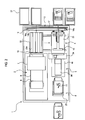
- Figs. 1 and 2 schematically show a machine for filling a bag with medicine according to the embodiment.
- This machine for filling a bag with medicine has a machine main body 1, which mainly includes a medicine bag printing portion 2, a medicine bag conveying portion 3, a medicine bag positioning portion 4, a medicine supply portion 5, and a medicine charging portion 6.
- the medicine bag printing portion 2 includes two upper and lower medicine bag printers 7, and strip-like medicine bags 9 are successively supplied to each medicine bag printer 7 from a medicine bag roll 8.
- the strip-like medicine bags 9 include a plurality of successive bags each previously formed into a bag open in a direction opposite to the conveying direction; they are cut into unit bags by a cutter 10 provided at the outlet portion of the medicine bag printing portion 2.
- the strip-like medicine bags 9 are formed of a translucent material, allowing medicine 11 accommodated therein to be visually checked. Affixed to the surfaces of the strip-like medicine bags 9 are a plurality of labels for printing.
- Each medicine bag printer 7 prints patient name, medicine name, information on medicine taking (use, dosage, etc.) and the like on each label based on prescription data or the like input from a host computer 12.
- a medicine bag 13 obtained by cutting the strip-like medicine bags 9 by the cutter 10 is supplied to a conveyor portion 21 includes three belts 21a that can be driven in synchronism with each other, and are transferred to a predetermined position before undergoing positioning.
- the medicine bag conveying portion 3 is constituted by a horizontal moving member 14, a vertical moving member 15, and a suction member 16.
- the horizontal moving member 14 is formed by stretching a belt 14c between pulleys 14a, 14b respectively arranged on the right-hand and left-hand sides of the machine main body 1.
- the entire horizontal moving member 14 is retained by a horizontal frame member 17.
- one pulley 14a is driven by a motor or the like (not shown) to rotate in normal/reverse rotating direction, the belt makes normal/reverse circulation movement, and the horizontal moving member 14 reciprocates in the X-axis direction.
- the vertical moving member 15 is formed by stretching a belt 15c between pulleys 15a, 15b respectively arranged on the upper and lower sides of the machine main body 1; it is substantially of the same construction as the horizontal moving member 14 except that the reciprocating direction is changed to the vertical one. It should be noted, however, that the horizontal frame member 17 is fixed to the belt 14c of the horizontal moving member 14, and that the whole reciprocates in the vertical direction (Z-direction) as the vertical moving member 15 is driven.
- the suction member 16 is mounted to the belt 15c of the vertical moving member 18 via a support arm 18.
- the suction member 16 is of a substantially I-shaped configuration and is constituted by a body portion 19 extending along the support arm 18 and suction portions 20 whose both end portions extend in two orthogonal directions.
- the body portion 19 is hollow, and is connected to a suction device (not shown); it is possible to suck the four corners of the medicine bag 13 through suction cylinders 21 downwardly extending from the distal ends (both ends) of each suction portion 20, thereby retaining the bag.
- the suction member 16 is reciprocated in the longitudinal direction (Y-axis direction) with respect to the support arm 18 by a longitudinal moving member constituted by pulleys and a belt.
- the medicine bag positioning portion 4 includes a rotation plate 23, a medicine bag opening portion 24, a medicine bag temporary stop portion 25 (see Fig. 8 ), and a medicine bag retaining arm 26.
- the rotation plate 23 is rotated through driving of a motor 23a around a support shaft 23e via pulleys 23b, 23d and a belt 23c, and can be set in a horizontal position and an inclined position in which the distal end thereof is directed obliquely downwards.
- the rotating position of the rotation plate 23 is judged based on whether or not a shield plate 23b provided at a shaft portion intercepts the light path of a sensor 23c (light emitting element and light receiving element) provided in the machine main body 1.
- the rotation plate 23 allows charging of medicine 11 into the medicine bag 13 placed on the top surface thereof, and allows, in the inclined position, the medicine bag 13 to be supplied to a bucket 27.
- Guide grooves 28 are formed in both side surfaces of the rotation plate 23, and two elongated holes 29 are formed therein to extend along both side portions.
- the medicine bag opening portion 24 includes an ascent/descent member 30.
- the ascent/descent member 30 is provided in a gate-shaped support frame 31 fixed to a frame 43 (support portion 43a of rotation plate 23) so as to be capable of ascending and descending.
- the ascent/descent member 30 includes an ascent/descent plate 30b urged downwardly by a spring 30a.
- the ascent/descent member 30 includes three rods 30a extending through an arch portion 31a of the support frame 31. Of the three rods 30a, the one situated at the center has a gear portion 30b, which is in mesh with a gear 30d provided on the rotation shaft of a motor 30c.
- the ascent/descent plate 30b ascends or descends via the rods 30a.
- the support portion 43a of the rotation plate 23 and the ascent/descent member 30 have at both ends suction ports 43b and 30f.
- the suction ports 43b and 30f are connected to a suction device (not shown) via a communication hole (not shown), and suck and retain from the outer side the opening portion of the medicine bag 13 placed on the rotation plate 23 in the horizontal position.
- the opening portion of the medicine bag 13 is opened.
- the arch portion 31a of the support frame 31 supports a presser member 32 of a substantially L-shaped configuration so as to allow rotation around a support shaft 32a between an opening position and a retaining position.
- the presser member 32 is urged toward the opening position by a spring 32b fitted onto the support shaft 32a.
- the presser member 32 includes with a roller 32c rolling on an inclined surface 33a and a vertical surface 33b of a guide portion 33 provided in the support frame 31.
- the roller 32c rolls on the inclined surface 33a, and the presser member 32 rotates counterclockwise around the support shaft 32a as shown in Fig. 8 .
- the presser member 32 retains the upper inner surface of the opened medicine bag 13.
- the medicine bag temporary stop portion 25 is constituted by four heating portions 25a provided on the support portion of the rotation plate 23, and a roller 25b (see Fig. 7 ) rotatably provided on the ascent/descent member 30 so as to be opposed to each heating portion 25a.
- the ascent/descent member 30 With the medicine bag 13 being positioned at a predetermined position on the rotation plate 23, the ascent/descent member 30 is lowered, and the opening portion of the medicine bag 13 is held between the heating portions 25a and the roller 25b to effect heating by supplying electricity to the heating portions 25a. Then, the opening portion of the medicine bag 13 is heat-sealed at four positions arranged at predetermined intervals in the width direction.
- the heat-sealed portions are arranged at such intervals as make it impossible or less liable for the medicine accommodated in the medicine bag 13 to be spilled out thereof.
- the heat sealing is effected to the degree that when the opening portion is pulled to both sides so as to extract the medicine 11 from the medicine bag 13, the heat-sealed portions are separated relatively easily to open the opening portion.
- the medicine bag retaining arm 26 is constituted by arm portions 34 that reciprocate along the guide grooves 28 of the rotation plate 23 and rotate around a support shaft 34a, and a connecting portion 35 connecting the two arm portions 34.
- Pressing portions 36 are provided at the two end portions of the connecting portion 35 through the intermediation of elastic portions 36a.
- the pressing portions 36 are formed of a material such as rubber which exhibits a large coefficient of friction with respect to the medicine bag 13.
- each bucket 27 is formed as a box open on the top side and has an outwardly extending flange portion 27a at the upper opening edge thereof. Further, a ridge 27b is formed on the bottom side portion of the outer surface of each bucket 27.
- the flange portion 27a of each bucket supports the ridge 27b of the upper bucket 27, thereby forming an accommodation space.
- the buckets 27 are supplied from the outside of the machine main body 1, and are conveyed to a position below the rotation plate 23. After the bags 13 are accommodated therein, the buckets are conveyed to the exterior of the machine main body 1 to be stacked together.
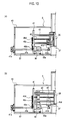
- the medicine supply portion 5 includes an outer container 37 serving as a first moving member, an ampoule extruding member 38 serving as a second moving member, a shutter member 39, and a cover member 40.
- the outer container 37 is formed as a box open on the top and front sides, and is fixed to a support member 41 via four slide shafts 42.
- a buffer member formed of urethane, sponge or the like is attached to the bottom surface of the outer container 37 so that the supplied medicine 11 may not suffer damage. The frictional resistance of the surface of this buffer member is minimized so that the medicine 11 may easily slide when the outer container 37 moves as described below.
- the support member 41 is fixed to a belt 41c stretched between pulleys 41a, 41b.
- the pulleys 41a, 41b are rotatably supported by the frame 43 of the machine main body 1.
- One pulley 41b is driven by a motor 41d to rotate in the normal or reverse direction.
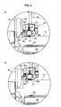
- the outer container 37 reciprocates in the directions indicated by the arrows in Fig. 5 , and is positioned at a waiting position shown in Fig. 5 and a supply position shown in Fig. 10(a) .
- a slider 58 reciprocates along a guide rail 57 provided on the frame 43.
- the slider 58 is provided for the purpose of effecting accurate positioning on the outer container 37 with respect to the frame 43.
- a portion to be detected is provided to extend along the guide rail 57, and this portion to be detected is detected by a sensor provided on the slider.
- a nut portion 44 which is threadedly engaged with a ball screw 45.
- the ball screw 45 is driven to rotate by the motor 45a via the pulleys 45b, 45d, and the belt 45c.
- the motor 45a is driven to rotate the ball screw 45 in the normal or reverse direction
- the position at which the nut portion 44 is threadedly engaged with the ball screw 45 is displaced in the axial direction.
- the outer container 37 reciprocates, and its positional relationship with the ampoule extruding member 38 described below varies.
- the upper edges of the forward ends of both side surfaces of the outer container 37 are formed in an arcuate configuration, thereby preventing damage of the medicine bag 13 when medicine is inserted into the medicine bag 13.
- the ampoule extruding member 38 is formed of a synthetic resin material, and is accommodated in the outer container 37, thereby forming a medicine storage region within the outer container 37.
- One end portion of the ball screw 45 is rotatably connected to the rear portion of the ampoule extruding member 38 through the intermediation of a bearing, and, at the same time, one end portion of each slide shaft 42 is connected thereto.
- the ampoule extruding member 38 reciprocates between the waiting position and the supply position together with the outer container 37.
- solely the outer container 37 is caused to retreat through rotation of the ball screw 45, it is possible to allow the medicine 11 in the medicine storage region to remain in the medicine bag 13.
- the ampoule extruding member 38 includes a guide surface 47, a detachment preventing portion 48, and a climbing suppressing portion 49.
- the material, the surface roughness, and the inclination angle of the guide surface 47 are set such that the medicine 11, supplied from a tray 50 via a charging port 54, can be smoothly supplied.
- the guide surface 47 is formed as a flat surface, it is also possible to adopt some other form, such as a convex surface arcuate in section or a concave surface arcuate in section.
- the guide surface 47 is formed as a convex surface, the tangential direction of the arc of its section becomes closer to the vertical direction on the bottom surface side of the outer container 37, and hence it is possible to eliminate the climbing suppressing portion 49.
- the detachment preventing portion 48 is formed by a ridge protruding upwardly from the upper edge portion of the guide surface 47. As described below, by causing the outer container 37 to retreat relative to the ampoule extruding member 38, it is possible to prevent the medicine 11 supplied onto the bottom surface of the outer container 37 from moving in the reverse direction via the guide surface 47 to flow to the exterior.
- the climbing suppressing portion 49 is formed by a vertical surface formed at the lower edge portion of the guide surface 47.
- the climbing suppressing portion 49 comes into contact with the medicine 11 supplied onto the bottom surface of the outer container 37, thereby preventing it from climbing onto the guide surface 47.
- a material such as rubber of large coefficient of friction is used for the vertical surface forming the climbing suppressing portion 49, it is advantageously possible to more effectively prevent the medicine 11 from climbing onto the guide surface.
- the shutter member 39 is a plate-like member provided on the support portion of the rotation plate 23 so as to be rotatable around a support shaft.
- a support shaft 39a includes a driven gear 51, and power is transmitted from a driving gear 53 provided on the rotation shaft of a motor (not shown) via an intermediate gear 52.
- the shutter member 39 rotates between a closing position where it closes front opening of the outer container 37 situated at the waiting position, and a retaining position where it is placed on the rotation plate 23 in the horizontal position and presses the lower inner surface of the medicine bag 13 whose opening is open.
- the cover member 40 is provided on the frame 43 of the machine main body 1 so as to cover the entire upper surface of the medicine supply portion 5, and has a charging port 54 to make it possible to supply the medicine 11 from the tray 50 to the medicine storage region.
- the charging port 54 is opened when the outer container 37 and the ampoule extruding member 38 are situated at the waiting position, making it possible to supply the medicine 11 to the medicine storage region via the guide surface 47 of the ampoule extruding member 38.
- the outer container 37 and the ampoule extruding member 38 advance toward the supply position, the charging of medicine 11 into the charging port 54 becomes impossible.
- the medicine charging portion 6 includes a lifter 55 and a swinging arm 56.
- the lifter 55 causes a support stand 55b to ascend and descend through driving a belt 55a arranged to extend in the vertical direction.
- the swinging arm 56 rotates the tray 50 conveyed to the upper position by the lifter 55 to place it in an inclined state, thereby charging the accommodated medicine 11 into the medicine supply portion 5 (charging port 54).
- the tray 50 is formed such that the end portion thereof, which is situated on the lower side when it is rotated by the swinging arm 56, is gradually reduced in width and depth toward the forward end. As a result, when the tray 50 is inclined by the swinging arm 56, the medicine 11 accommodated in the tray 50 is gathered and charged smoothly into the charging port 54.
- the medicine bag printing portion 2, the medicine bag conveying portion 3, the medicine bag positioning portion 4, the medicine supply portion 5, and the medicine charging portion 6 are drive-controlled by a control device 59 based on input data from a host computer 12.
- the supply of the medicine 11 to the tray 50 is effected by a conventionally well-known medicine supply device.
- the medicine 11 includes objects such as ampoules or vials, which are subject to damage by impact.
- a medicine supply device (not shown) supplies the corresponding medicine 11 into the tray 50 based on the prescription data. Then, the tray 50 to which the medicine 11 has been supplied is conveyed to the medicine charging portion 6.
- the control device 59 drive-controls the motor 41d based on an input signal from the host computer 12, and moves the outer container 37 and the ampoule extruding member 38 to the waiting position, thereby closing the charging port 54 of the cover member 40.
- the guide surface 47 of the ampoule extruding member 38 is continuous with the charging port 54, and the medicine 11 charged from the tray 50 can be smoothly guided to the medicine storage region.
- the shutter member 39 is rotated to the closing position so that the medicine 11 supplied to the medicine storage region may not be spilled.
- the lifter 55 is driven to move the tray 50 to the upper position, and the swinging arm 56 is swung, whereby the medicine 11 in the tray 50 is supplied to the medicine storage region via the charging port 54.
- the medicine 11 rolls or slides on the guide surface 47 until it reaches the bottom surface of the outer container (see Fig. 11 (a) ).
- the guide surface 47 exhibits small coefficient of friction, and helps to supply the medicine 11, in particular, the medicine 11 subject to damage such as ampoules to the bottom surface. Even when the supplied medicine 11 is supplied with momentum via the guide surface 47, the bottom surface of the outer container 37 mitigates the impact.
- the medicine bag 13 is supplied. That is, the control device 59 drives the medicine bag printer 7 based on the prescription data received from the host computer 12, and effect corresponding printing on each label of the medicine bag strip wound back from the medicine bag roll 8. Then, the medicine bag strip is cut by the cutter 10 to obtain the medicine bag 13, which is supplied to a conveyor portion 22. In the conveyor portion 22, a belt 22a is driven, and positioning is effected on the supplied medicine bag 13 at a predetermined position.
- the medicine bag conveying portion 3 (horizontal moving member 14, vertical moving member 15, etc.) is drive-controlled, and the suction cylinders 21 of the suction member 16 are opposed to the four corners of the medicine bag 13. Then, a suction device (not shown) is driven, and the medicine bag 13 is sucked by the suction cylinders 21, the suction member 16 retaining the medicine bag 13. Subsequently, the medicine bag conveying portion 3 is drive-controlled, and the medicine bag 13 is conveyed to the rotation plate 23 (see Fig. 11(a) ). The placing position on the rotation plate 23 is specified based on previously registered coordinate data.
- Both sides of the opening of the medicine bag 13 supplied onto the rotation plate 23 are sucked via the suction holes 23a and 30f, and, by upwardly moving the ascent/descent member 30, the medicine bag 13 is opened to allow charging of the medicine 11.
- the presser member 32 rotates, and the upper inner surface of the opening portion of the medicine bag 13 is pressed. Further, the shutter member 39 is rotated to press the lower inner surface of the opening portion of the medicine bag 13 (see Fig. 11(b) ).
- the motor 46d is driven to cause the outer container 37 and the ampoule extruding member 38 to enter the medicine bag 13 before stopping at the supply position (see Figs. 9 , 10(a) , and 11(c) ). Since it is possible to reliably open the opening of the medicine bag 13 in a predetermined size by the shutter member 39 and the presser member 32, it is possible to allow the outer container 37 and the ampoule extruding member 38 to smoothly enter the medicine bag 13. Since the forward end portion of the side wall of the outer container 37 is formed in an arcuate configuration, there is no fear of the medicine bag 13 being damaged.
- the medicine storage region is situated completely within the medicine bag 13. Then, the motor 45a is driven to retract solely the outer container 37 from the medicine bag 13 (see Figs. 10(b) and 11(d) ). As a result, the medicine 11 in the medicine storage region ceases to be supported by the bottom surface of the outer container 37, and is forcibly caused to remain in the medicine bag 13 by the ampoule extruding member 38, more specifically, by the climbing suppressing portion 49 and the guide surface 47. In this case, the medicine 11 simply undergoes regulation in position by the ampoule extruding member 38, and hence its position in the medicine bag 13 is scarcely changed. Thus, there occurs substantially no such problem as medicine damage due to collision of medicines with each other.
- the medicine 11 slides on the guide surface 47 to move to the upper side, it is prevented from flowing out by the detachment preventing portion 48. Further, the inner surface of the medicine bag 13 is situated in the vicinity of the upper side of the detachment preventing portion, and hence the medicine 11 does not flow out of the medicine bag 13.
- the motor is driven to move both the outer container 37 and the ampoule extruding member 38 out of the medicine bag 13 (see Fig. 11(e) ). Further, the ascent/descent member 30 is lowered, and the positioning of the medicine bag 13 by the shutter member 39 and the presser member 32 is cancelled. As a result, the opening portion of the medicine bag 13 is held between the support portion and the ascent/descent member 30.
- electricity is supplied to the heating portion 25a to effect temporary stopping through heat sealing at four positions of the opening portion of the medicine bag 13.
- the medicine bag retaining arm 26 is caused to slide along the rotation plate 23, and is rotated to bring the pressing portion 36 into press contact with the portion in the vicinity of the opening (both side portions) of the medicine bag 13 (see Fig. 11(f) ).
- the elongated holes 29 are situated on the side of the medicine bag 13 opposite to the side where it is held in press contact with the pressing portion 36.
- the rotation plate 23 is rotated to the inclined position (see Fig. 12(a) ).
- the medicine bag retaining arm 26 is moved (see Fig. 12(b) ).
- the medicine bag retaining arm 26 is rotated to the former position, whereby the retaining state of the medicine bag 13 is cancelled, and the medicine bag 13 is supplied into the bucket 27 (see Fig. 12(c) ). In this way, the medicine bag 13 whose opening has already been temporarily stopped can be smoothly conveyed to the bucket 27 supplied to the predetermined position.
- the medicine 11 in the tray 50 can be charged into the medicine storage region in the outer container 37 via the charging port 54.
- the medicine 11 can be smoothly guided to the medicine storage region by the guide surface 47 continuous with the inclined tray 50.
- solely the outer container 37 is retracted, whereby the medicine 11 in the medicine storage region remains in the medicine bag 13.
- medicine 11 it is possible to cause medicine 11 to remain in the medicine bag 13 after moving it into the medicine bag 13 while maintaining the positional relationship between medicines.
- the operation of filling the medicine bag 13 with the medicine 11 is conducted at high speed, there is no fear of the medicine suffering damage from collision of medicines with each other.
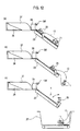
- the first moving member is formed by the outer container 37, it may also be formed by a belt conveyor 100 as shown in Fig. 13 .
- the belt conveyor 100 has a simple construction in which a belt 102 is stretched between a pair of rotatable pulleys 101 arranged at a predetermined interval.
- the medicine 11 causes the belt 102 to move.
- no excessive load is applied to the medicine 11, which is allowed to smoothly remain in the medicine bag 13.
- the belt conveyor 100 and the ampoule extruding member 38 are retracted out of the medicine bag 13 (see Fig. 13(e) ), and the opening of the medicine bag 13 is maintained in the closed state by the medicine bag retaining arm 26 (see Fig. 13(f) ) before effecting transfer to the bucket 27.
- the second moving member includes the ampoule extruding member 38 as shown in Figs. 5 , 6 , etc., it is also possible to adopt a form as shown in Fig. 14 .
- the guide surface 47 (including the climbing suppressing portion 49) of the ampoule extruding member 38 is constituted by first inclines surface 111 and a second inclined surface 112 gradually inclined downwards toward both sides from a ridge 110, and a third inclined surface 113 inclined gradually downwards from the central portion toward the forward end.
- the charged medicines 11 are aligned in the charging direction by the first and second inclined surfaces 111 and 112.
- the medicines 11 aligned in the charging direction do not easily move toward the ampoule extruding member 38 side.
- the medicines 11 (mainly ampoules) that tend to move on the third inclined surface 113 are divided into both sides by the ridge 110, and respectively move (roll or slide) on the first inclined surface 111 and the second inclined surface 112, or move as they are on the third inclined surface 113 to remain in the medicine bag 12.
- the medicines 11 are caused to remain in the medicine bag 13 in a dispersed state, and hence it is possible to adequately prevent a problem such as medicine damage from collision of the medicines 11 with each other.
- Fig. 13 is formed by three inclined surfaces, it is also possible to form it by two or four or more inclined surfaces. In brief, any construction will do as long as it helps to disperse the medicines 11 tending to climb onto the inclined surfaces through retreat of the outer container 37, thereby allowing the medicines 11 to remain in the medicine bag 13.
- the outer container 37 is formed so as to have a semi-arc-like sectional configuration and as to be gradually reduced in radius of curvature toward the forward end, and the ampoule extruding member 38 is accordingly formed such that its bottom surface swells in an arcuate fashion, with an elliptical inclined surface 115 being provided at the forward end.
- the supplied medicines 11 mainly ampoules
- the medicines 11 are aligned in orientation along the longitudinal direction.
- Fig. 14(c) instead of the construction having the outer container 37 and the ampoule extruding member 38 shown in Fig. 14(b) , there is adopted a construction having solely the outer container 37, which is vertically (between the horizontal position and the inclined position) rotatable around the forward end as indicated by the arrows. In the horizontal position, the outer container 37 moves into the medicine bag 13, with the medicines 11 placed thereon, then it is rotated to the inclined position, where the medicines 11 placed thereon are forcibly charged into the medicine bag 13, and thereafter, it moves out of the medicine bag (it may be temporarily restored to the horizontal position).
- Fig. 15 is a schematic front view of a machine for filling a bag with medicine according to another embodiment.
- This machine for filling a bag with medicine is formed, instead of being formed by the first and second moving members, solely by a belt conveyor 120 and guide walls 121 on both sides thereof.
- a belt 123 is stretched between a pair of pulleys 122, and one pulley 122 is capable of normal and reverse rotation through driving of a motor (not shown).
- the medicine 11 is directly charged from the medicine charging portion 6 and is placed on the belt conveyor 120.
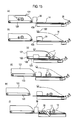
- the medicines are charged onto the belt conveyor 120 from the medicine charging portion 6 (see Fig. 15(a) ), and the medicine bag 13 is opened by the suction holes 43b and 30f as in the above-mentioned embodiment (see Fig. 15(b) ). Then, after the belt conveyor 120 is moved into the medicine bag 13, the belt conveyor 120 is driven, and the medicines 11 placed thereon are forcibly supplied into the medicine bag 13 (see Fig. 15(c) ).
- the configuration and size of the medicines are stored in a storage means (e.g., a hard disk) (not shown), and the belt conveyor 120 is gradually retracted out of the medicine bag 13 so that the medicines 11 may be properly accommodated in the medicine bag 13 based on the data and the number of medicines to be accommodated in the medicine bag 13. From this onward, the same processes (see Figs. 15(d) through 15(f) ) as those of the above embodiment are conducted.
- a storage means e.g., a hard disk
- control device drive control means
- 100 ... belt conveyor, 101 ... pulley, 102 ... belt, 110 ... ridge, 111 ... first inclines surface, 112 ... second inclined surface, 113 ... third inclined surface, 115 ... inclined surface, 120 ... belt conveyor, 121 ... guide wall, 122 ... pulley, 123 ... belt
Landscapes
- Engineering & Computer Science (AREA)
- Mechanical Engineering (AREA)
- Basic Packing Technique (AREA)
- Medical Preparation Storing Or Oral Administration Devices (AREA)
Applications Claiming Priority (2)
| Application Number | Priority Date | Filing Date | Title |
|---|---|---|---|
| JP2006073460A JP5011767B2 (ja) | 2006-03-16 | 2006-03-16 | 薬剤袋詰装置 |
| PCT/JP2007/054446 WO2007108325A1 (ja) | 2006-03-16 | 2007-03-07 | 薬剤袋詰装置 |
Publications (3)
| Publication Number | Publication Date |
|---|---|
| EP2000409A2 true EP2000409A2 (de) | 2008-12-10 |
| EP2000409A9 EP2000409A9 (de) | 2009-03-18 |
| EP2000409A4 EP2000409A4 (de) | 2010-07-07 |
Family
ID=38522358
Family Applications (1)
| Application Number | Title | Priority Date | Filing Date |
|---|---|---|---|
| EP07737960A Withdrawn EP2000409A4 (de) | 2006-03-16 | 2007-03-07 | Maschine zum füllen eines beutels mit einem arzneimittel |
Country Status (6)
| Country | Link |
|---|---|
| US (1) | US7934356B2 (de) |
| EP (1) | EP2000409A4 (de) |
| JP (1) | JP5011767B2 (de) |
| KR (1) | KR101344969B1 (de) |
| CN (1) | CN101405187B (de) |
| WO (1) | WO2007108325A1 (de) |
Families Citing this family (15)
| Publication number | Priority date | Publication date | Assignee | Title |
|---|---|---|---|---|
| JP5011767B2 (ja) * | 2006-03-16 | 2012-08-29 | 株式会社湯山製作所 | 薬剤袋詰装置 |
| US20110030319A1 (en) * | 2009-08-10 | 2011-02-10 | O'malley Martin | Machine |
| US20130247512A1 (en) * | 2012-03-26 | 2013-09-26 | Eggo Haschke | Automated loader with cone horn |
| JP6008684B2 (ja) * | 2012-10-12 | 2016-10-19 | 株式会社三協システム | 包装袋供給装置 |
| US20140108028A1 (en) | 2012-10-12 | 2014-04-17 | Mckesson Automation Inc. | Apparatuses, systems, and methods for anticipating and delivering medications from a central pharmacy to a patient in a healthcare facility |
| US9150119B2 (en) | 2013-03-15 | 2015-10-06 | Aesynt Incorporated | Apparatuses, systems, and methods for anticipating and delivering medications from a central pharmacy to a patient using a track based transport system |
| CN103384100B (zh) * | 2013-08-09 | 2016-07-06 | 昆山市佰奥自动化设备科技有限公司 | 数码皮带驱动模组 |
| JP2017226427A (ja) * | 2016-06-20 | 2017-12-28 | 三菱電機株式会社 | 袋詰め装置及びワークの袋詰め方法 |
| CN106205072B (zh) * | 2016-09-30 | 2018-09-28 | 厦门巨烨科技有限公司 | 一种卷带式连续药袋的智能服药提醒装置 |
| CN109589266A (zh) * | 2018-11-15 | 2019-04-09 | 黄丽佳 | 一种煎药效果好的自动化煎药机 |
| JP2020115939A (ja) * | 2019-01-18 | 2020-08-06 | 株式会社ソルブ | 医療用ラベル認識装置、医療用ラベル認識システム、及び医療用ラベル認識方法 |
| CN110844197B (zh) * | 2019-11-27 | 2024-11-01 | 五邑大学 | 电视机配件自动包装设备 |
| EP4514694A1 (de) * | 2022-06-20 | 2025-03-05 | Sealed Air NZ | Vorrichtung zum verpacken von produkten |
| CN115771660A (zh) * | 2022-12-09 | 2023-03-10 | 安徽庆丰余防伪科技有限公司 | 一种用于防伪标签的铺贴装置 |
| CN116531894B (zh) * | 2023-05-08 | 2023-12-29 | 哈尔滨悟山青环保科技有限公司 | 一种甲醛吸附材料制备工艺 |
Family Cites Families (21)
| Publication number | Priority date | Publication date | Assignee | Title |
|---|---|---|---|---|
| US4062169A (en) * | 1975-03-20 | 1977-12-13 | Brdr. Schur International A.S. | Packaging machines |
| US4476664A (en) * | 1980-11-20 | 1984-10-16 | E.C.H. Will (Gmbh & Co.) | Apparatus for introducing stacks of paper sheets or the like into cartons or analogous receptacles |
| US4706440A (en) * | 1986-12-09 | 1987-11-17 | Precision Automation Co., Inc. | Method and apparatus for packaging expansile articles |
| JPH04128101A (ja) * | 1990-09-12 | 1992-04-28 | Kao Corp | 物品の包装方法 |
| US5195303A (en) * | 1992-05-29 | 1993-03-23 | Philip Morris Incorporated | Apparatus for automatic bagging of compressed tobacco |
| US5249409A (en) * | 1992-06-02 | 1993-10-05 | Mhb Industries Corp. | Method and apparatus for manufacture of wicketed bags with an encapsulated article and the bags formed thereby |
| DE9310969U1 (de) * | 1993-07-22 | 1994-11-24 | Robert Bosch Gmbh, 70469 Stuttgart | Vorrichtung zum Einschieben von Beutelpackungen o.dgl. nachgiebiger Gegenstände in Faltschachteln |
| JP2842180B2 (ja) * | 1993-10-29 | 1998-12-24 | 日本精機株式会社 | 包装装置 |
| US5452559A (en) * | 1994-08-08 | 1995-09-26 | Lipes; Arnold | Bagging machine with side bag gripping and transfer mechanism |
| JPH0872813A (ja) * | 1994-08-29 | 1996-03-19 | Yamazaki Kikai Seisakusho:Kk | 人参等の包装装置 |
| US5685129A (en) * | 1996-06-14 | 1997-11-11 | Metal Container Corporation | Automatic can lid bag sealer |
| JPH10323380A (ja) * | 1997-03-25 | 1998-12-08 | Yuyama Seisakusho:Kk | アンプル仕分用袋 |
| IT1296654B1 (it) * | 1997-12-17 | 1999-07-14 | Ravizza Packaging Srl | Metodo e macchina per il confezionamento di articoli in involucri di materiale flessibile. |
| JP4368956B2 (ja) * | 1998-03-24 | 2009-11-18 | 株式会社湯山製作所 | アンプル袋詰め装置 |
| US6691490B1 (en) * | 1998-06-30 | 2004-02-17 | Kabushiki Kaisha Yuyama Seisakusho | Injection drug packaging device |
| JP4577918B2 (ja) * | 1998-09-09 | 2010-11-10 | 株式会社湯山製作所 | アンプル袋詰め装置 |
| DE19959408A1 (de) * | 1999-12-10 | 2001-06-13 | Buehler Optima Maschf | Vorrichtung und Verfahren zum Einschieben von Gegenständen in einen geöffneten Beutel |
| US6351926B1 (en) * | 2000-01-19 | 2002-03-05 | Automated Packaging Systems, Inc. | Packaging system |
| JP2004148033A (ja) | 2002-11-01 | 2004-05-27 | Tosho Inc | 薬袋袋詰機 |
| JP2005153903A (ja) * | 2003-11-21 | 2005-06-16 | Tosho Inc | 薬剤袋詰機 |
| JP5011767B2 (ja) * | 2006-03-16 | 2012-08-29 | 株式会社湯山製作所 | 薬剤袋詰装置 |
-
2006
- 2006-03-16 JP JP2006073460A patent/JP5011767B2/ja not_active Expired - Fee Related
-
2007
- 2007-03-07 WO PCT/JP2007/054446 patent/WO2007108325A1/ja not_active Ceased
- 2007-03-07 CN CN2007800093112A patent/CN101405187B/zh not_active Expired - Fee Related
- 2007-03-07 EP EP07737960A patent/EP2000409A4/de not_active Withdrawn
- 2007-03-07 US US12/293,271 patent/US7934356B2/en not_active Expired - Fee Related
-
2008
- 2008-09-12 KR KR1020087022329A patent/KR101344969B1/ko not_active Expired - Fee Related
Also Published As
| Publication number | Publication date |
|---|---|
| US20090084070A1 (en) | 2009-04-02 |
| JP5011767B2 (ja) | 2012-08-29 |
| EP2000409A4 (de) | 2010-07-07 |
| CN101405187B (zh) | 2012-10-10 |
| KR20080106250A (ko) | 2008-12-04 |
| WO2007108325A1 (ja) | 2007-09-27 |
| CN101405187A (zh) | 2009-04-08 |
| EP2000409A9 (de) | 2009-03-18 |
| JP2007246132A (ja) | 2007-09-27 |
| KR101344969B1 (ko) | 2013-12-24 |
| US7934356B2 (en) | 2011-05-03 |
Similar Documents
| Publication | Publication Date | Title |
|---|---|---|
| EP2000409A2 (de) | Maschine zum füllen eines beutels mit einem arzneimittel | |
| US7988400B2 (en) | Vial conveyance device and arm for the same | |
| KR102404991B1 (ko) | 약제 분류 장치 및 약제 분류 방법 | |
| KR101402372B1 (ko) | 왕복식 삽입장치 | |
| US20100147868A1 (en) | Apparatus for releasing drugs | |
| KR20170068285A (ko) | 약제의 블리스터 포장 장치 | |
| KR20170068279A (ko) | 약제의 블리스터 포장 장치 | |
| KR20180043215A (ko) | 약제의 블리스터 포장 장치 | |
| CN216569247U (zh) | 一种上药机械手及自动发药机 | |
| CN104665117B (zh) | 一种半自动化的鞋料运送设备 | |
| CN104803031B (zh) | 针剂的包装机构 | |
| CN107284743A (zh) | 医疗针剂的调配包装装置 | |
| ES2770307T3 (es) | Aparato de inserción | |
| CN108706155A (zh) | 放纸放盖装置 | |
| JP2020169039A (ja) | 充填封入装置および充填封入方法 | |
| KR20170068284A (ko) | 약제의 블리스터 포장 장치 | |
| KR102531177B1 (ko) | 블리스터 팩용 커버 부착 유닛 및 이를 구비한 약제의 블리스터 팩킹 장치 | |
| KR20120047717A (ko) | 라벨부착장치 | |
| CN220131302U (zh) | 加药模块 | |
| CN215796194U (zh) | 一种自动发药机用自动取药平台 | |
| KR102531178B1 (ko) | 블리스터 팩용 블리스터 시트 공급 유닛 및 이를 구비한 약제의 블리스터 팩킹 장치 | |
| CN220131301U (zh) | 上药模块 | |
| CN222728458U (zh) | 一种注射用透明质酸钠的旋杆贴标设备 | |
| CN218433075U (zh) | 一种发药机用补药装置 | |
| JP7353129B2 (ja) | ワーク投入装置、ワーク投入方法およびワーク収納システム |
Legal Events
| Date | Code | Title | Description |
|---|---|---|---|
| PUAI | Public reference made under article 153(3) epc to a published international application that has entered the european phase |
Free format text: ORIGINAL CODE: 0009012 |
|
| 17P | Request for examination filed |
Effective date: 20081016 |
|
| AK | Designated contracting states |
Kind code of ref document: A2 Designated state(s): AT BE BG CH CY CZ DE DK EE ES FI FR GB GR HU IE IS IT LI LT LU LV MC MT NL PL PT RO SE SI SK TR |
|
| PUAB | Information related to the publication of an a document modified or deleted |
Free format text: ORIGINAL CODE: 0009199EPPU |
|
| A4 | Supplementary search report drawn up and despatched |
Effective date: 20100604 |
|
| RIC1 | Information provided on ipc code assigned before grant |
Ipc: B65B 39/12 20060101ALI20100528BHEP Ipc: B65B 1/30 20060101AFI20071009BHEP Ipc: B65B 5/06 20060101ALI20100528BHEP Ipc: B65B 17/00 20060101ALI20100528BHEP Ipc: A61J 3/00 20060101ALI20100528BHEP |
|
| 17Q | First examination report despatched |
Effective date: 20110208 |
|
| GRAP | Despatch of communication of intention to grant a patent |
Free format text: ORIGINAL CODE: EPIDOSNIGR1 |
|
| RIC1 | Information provided on ipc code assigned before grant |
Ipc: B65B 5/06 20060101ALI20120615BHEP Ipc: B65B 43/34 20060101ALI20120615BHEP Ipc: B65B 5/04 20060101AFI20120615BHEP Ipc: A61J 3/00 20060101ALI20120615BHEP Ipc: B65B 39/12 20060101ALI20120615BHEP |
|
| DAX | Request for extension of the european patent (deleted) | ||
| RIN1 | Information on inventor provided before grant (corrected) |
Inventor name: FUJIKAWA, TAKAYUKI Inventor name: TSUJI, HIDENORI Inventor name: YUYAMA, SHOJI |
|
| STAA | Information on the status of an ep patent application or granted ep patent |
Free format text: STATUS: THE APPLICATION IS DEEMED TO BE WITHDRAWN |
|
| 18D | Application deemed to be withdrawn |
Effective date: 20121123 |