EP2000375B1 - Système de commande de pression hydraulique pour frein de véhicule - Google Patents
Système de commande de pression hydraulique pour frein de véhicule Download PDFInfo
- Publication number
- EP2000375B1 EP2000375B1 EP08010197A EP08010197A EP2000375B1 EP 2000375 B1 EP2000375 B1 EP 2000375B1 EP 08010197 A EP08010197 A EP 08010197A EP 08010197 A EP08010197 A EP 08010197A EP 2000375 B1 EP2000375 B1 EP 2000375B1
- Authority
- EP
- European Patent Office
- Prior art keywords
- hydraulic pressure
- target
- pressure
- rotational speed
- mode
- Prior art date
- Legal status (The legal status is an assumption and is not a legal conclusion. Google has not performed a legal analysis and makes no representation as to the accuracy of the status listed.)
- Ceased
Links
- 239000012530 fluid Substances 0.000 claims description 43
- 230000007423 decrease Effects 0.000 claims description 6
- 238000010586 diagram Methods 0.000 description 17
- 230000001965 increasing effect Effects 0.000 description 10
- 238000000034 method Methods 0.000 description 5
- 230000003213 activating effect Effects 0.000 description 1
- 238000007796 conventional method Methods 0.000 description 1
- 238000001514 detection method Methods 0.000 description 1
- 238000007599 discharging Methods 0.000 description 1
- 230000000694 effects Effects 0.000 description 1
- 230000002708 enhancing effect Effects 0.000 description 1
- 239000013642 negative control Substances 0.000 description 1
- 239000013641 positive control Substances 0.000 description 1
- 230000001737 promoting effect Effects 0.000 description 1
- 230000000087 stabilizing effect Effects 0.000 description 1
Images







Classifications
-
- B—PERFORMING OPERATIONS; TRANSPORTING
- B60—VEHICLES IN GENERAL
- B60T—VEHICLE BRAKE CONTROL SYSTEMS OR PARTS THEREOF; BRAKE CONTROL SYSTEMS OR PARTS THEREOF, IN GENERAL; ARRANGEMENT OF BRAKING ELEMENTS ON VEHICLES IN GENERAL; PORTABLE DEVICES FOR PREVENTING UNWANTED MOVEMENT OF VEHICLES; VEHICLE MODIFICATIONS TO FACILITATE COOLING OF BRAKES
- B60T8/00—Arrangements for adjusting wheel-braking force to meet varying vehicular or ground-surface conditions, e.g. limiting or varying distribution of braking force
- B60T8/32—Arrangements for adjusting wheel-braking force to meet varying vehicular or ground-surface conditions, e.g. limiting or varying distribution of braking force responsive to a speed condition, e.g. acceleration or deceleration
- B60T8/34—Arrangements for adjusting wheel-braking force to meet varying vehicular or ground-surface conditions, e.g. limiting or varying distribution of braking force responsive to a speed condition, e.g. acceleration or deceleration having a fluid pressure regulator responsive to a speed condition
- B60T8/48—Arrangements for adjusting wheel-braking force to meet varying vehicular or ground-surface conditions, e.g. limiting or varying distribution of braking force responsive to a speed condition, e.g. acceleration or deceleration having a fluid pressure regulator responsive to a speed condition connecting the brake actuator to an alternative or additional source of fluid pressure, e.g. traction control systems
- B60T8/4809—Traction control, stability control, using both the wheel brakes and other automatic braking systems
- B60T8/4827—Traction control, stability control, using both the wheel brakes and other automatic braking systems in hydraulic brake systems
- B60T8/4863—Traction control, stability control, using both the wheel brakes and other automatic braking systems in hydraulic brake systems closed systems
- B60T8/4872—Traction control, stability control, using both the wheel brakes and other automatic braking systems in hydraulic brake systems closed systems pump-back systems
-
- B—PERFORMING OPERATIONS; TRANSPORTING
- B60—VEHICLES IN GENERAL
- B60T—VEHICLE BRAKE CONTROL SYSTEMS OR PARTS THEREOF; BRAKE CONTROL SYSTEMS OR PARTS THEREOF, IN GENERAL; ARRANGEMENT OF BRAKING ELEMENTS ON VEHICLES IN GENERAL; PORTABLE DEVICES FOR PREVENTING UNWANTED MOVEMENT OF VEHICLES; VEHICLE MODIFICATIONS TO FACILITATE COOLING OF BRAKES
- B60T8/00—Arrangements for adjusting wheel-braking force to meet varying vehicular or ground-surface conditions, e.g. limiting or varying distribution of braking force
- B60T8/32—Arrangements for adjusting wheel-braking force to meet varying vehicular or ground-surface conditions, e.g. limiting or varying distribution of braking force responsive to a speed condition, e.g. acceleration or deceleration
- B60T8/34—Arrangements for adjusting wheel-braking force to meet varying vehicular or ground-surface conditions, e.g. limiting or varying distribution of braking force responsive to a speed condition, e.g. acceleration or deceleration having a fluid pressure regulator responsive to a speed condition
- B60T8/36—Arrangements for adjusting wheel-braking force to meet varying vehicular or ground-surface conditions, e.g. limiting or varying distribution of braking force responsive to a speed condition, e.g. acceleration or deceleration having a fluid pressure regulator responsive to a speed condition including a pilot valve responding to an electromagnetic force
-
- B—PERFORMING OPERATIONS; TRANSPORTING
- B60—VEHICLES IN GENERAL
- B60T—VEHICLE BRAKE CONTROL SYSTEMS OR PARTS THEREOF; BRAKE CONTROL SYSTEMS OR PARTS THEREOF, IN GENERAL; ARRANGEMENT OF BRAKING ELEMENTS ON VEHICLES IN GENERAL; PORTABLE DEVICES FOR PREVENTING UNWANTED MOVEMENT OF VEHICLES; VEHICLE MODIFICATIONS TO FACILITATE COOLING OF BRAKES
- B60T8/00—Arrangements for adjusting wheel-braking force to meet varying vehicular or ground-surface conditions, e.g. limiting or varying distribution of braking force
- B60T8/32—Arrangements for adjusting wheel-braking force to meet varying vehicular or ground-surface conditions, e.g. limiting or varying distribution of braking force responsive to a speed condition, e.g. acceleration or deceleration
- B60T8/34—Arrangements for adjusting wheel-braking force to meet varying vehicular or ground-surface conditions, e.g. limiting or varying distribution of braking force responsive to a speed condition, e.g. acceleration or deceleration having a fluid pressure regulator responsive to a speed condition
- B60T8/36—Arrangements for adjusting wheel-braking force to meet varying vehicular or ground-surface conditions, e.g. limiting or varying distribution of braking force responsive to a speed condition, e.g. acceleration or deceleration having a fluid pressure regulator responsive to a speed condition including a pilot valve responding to an electromagnetic force
- B60T8/3615—Electromagnetic valves specially adapted for anti-lock brake and traction control systems
- B60T8/3655—Continuously controlled electromagnetic valves
-
- B—PERFORMING OPERATIONS; TRANSPORTING
- B60—VEHICLES IN GENERAL
- B60T—VEHICLE BRAKE CONTROL SYSTEMS OR PARTS THEREOF; BRAKE CONTROL SYSTEMS OR PARTS THEREOF, IN GENERAL; ARRANGEMENT OF BRAKING ELEMENTS ON VEHICLES IN GENERAL; PORTABLE DEVICES FOR PREVENTING UNWANTED MOVEMENT OF VEHICLES; VEHICLE MODIFICATIONS TO FACILITATE COOLING OF BRAKES
- B60T8/00—Arrangements for adjusting wheel-braking force to meet varying vehicular or ground-surface conditions, e.g. limiting or varying distribution of braking force
- B60T8/32—Arrangements for adjusting wheel-braking force to meet varying vehicular or ground-surface conditions, e.g. limiting or varying distribution of braking force responsive to a speed condition, e.g. acceleration or deceleration
- B60T8/34—Arrangements for adjusting wheel-braking force to meet varying vehicular or ground-surface conditions, e.g. limiting or varying distribution of braking force responsive to a speed condition, e.g. acceleration or deceleration having a fluid pressure regulator responsive to a speed condition
- B60T8/40—Arrangements for adjusting wheel-braking force to meet varying vehicular or ground-surface conditions, e.g. limiting or varying distribution of braking force responsive to a speed condition, e.g. acceleration or deceleration having a fluid pressure regulator responsive to a speed condition comprising an additional fluid circuit including fluid pressurising means for modifying the pressure of the braking fluid, e.g. including wheel driven pumps for detecting a speed condition, or pumps which are controlled by means independent of the braking system
- B60T8/404—Control of the pump unit
- B60T8/4059—Control of the pump unit involving the rate of delivery
Definitions
- the present invention relates to a vehicle brake hydraulic pressure control system including a hydraulic pressure generating source which outputs hydraulic pressure in response to operation of a brake pedal, wheel brakes which operate by the action of hydraulic pressure, a hydraulic pressure control unit which has a pump driven by an electric motor and a normally open solenoid valve interposed between a hydraulic pressure path to which a discharge side of the pump is connected and the hydraulic pressure generating source and which is interposed between the wheel brakes and the hydraulic pressure generating source in such a manner as to adjust hydraulic pressures at the wheel brakes, brake hydraulic pressure detecting unit which detects hydraulic pressures at the wheel brakes, and a controller which includes a target wheel brake pressure setting unit for setting target hydraulic pressures for the wheel brakes for controlling the operation of the hydraulic pressure control unit so that the hydraulic pressures at the wheel brakes become target hydraulic pressures set by the target wheel brake pressure setting unit.
- a vehicle brake hydraulic pressure control system like this has already been known in, for example, Japanese Patent Unexamined Publication No. JP-A-2004-196235 .
- hydraulic pressures built up in the wheel brakes can be controlled by adjusting the hydraulic pressure in the hydraulic pressure path which is connected to the discharge side of the pump by driving the pump by the electric motor and controlling the normally open solenoid valve, which is interposed between the hydraulic pressure path and the hydraulic pressure generating source, to open or close in such a state that no hydraulic pressure is outputted from the hydraulic pressure generating unit.
- WO 99/58380 A1 and DE 10341027 A1 show vehicle brake hydraulic pressure control systems of the type wherein the pump (-motor) and the normally open solenoid valve interposed between the sub hydraulic pressure path and the hydraulic pressure generating source are both continuously variably controlled according to an established need.
- the invention has been made in view of the situations, and an object thereof is to provide a vehicle brake hydraulic pressure control system which can prevent the generation of overshoot while enhancing the response and toughness with respect to disturbance.
- a vehicle brake hydraulic pressure control system including:
- the vehicle brake hydraulic pressure control system further includes:
- controller (C) further includes:
- a master cylinder M in an embodiment corresponds to the hydraulic pressure generating unit of the invention
- a regulator valve 7 in the embodiment corresponds to the normally open solenoid valve of the invention
- a target rotational speed operating module 37 in the embodiment corresponds to the target rotational speed setting unit of the invention
- a left front wheel disc brake BA and a right rear disc brake BB in the embodiment correspond to the wheel brakes of the invention.
- the electric motor is controlled so that the rotational speed detected by the motor rotational speed detecting unit becomes the target rotational speed set in the target rotational speed setting unit and, when the deviation between the rotational speed detected in the motor rotational speed detecting unit and the rotational speed set in the target rotational speed setting unit is large, the normally open solenoid valve is controlled in such a manner that a controlled variable of the normally open solenoid valve becomes smaller than when the deviation is small. Therefore, the controlled variable of the normally open solenoid valve is made small when the pump starts discharging brake fluid so that the generation of overshoot can be prevented even when the discharge amount of the pump reaches a predetermined value at the initial stage of the control. Further, after the rotational speed deviation (the target rotational speed - the actual rotational speed) becomes small, the controlled variable of the normally open solenoid valve is made large so that the response and toughness with respect to disturbance can be enhanced.
- Figs. 1 to 15 show an embodiment of the invention.
- a master cylinder M which is a primary hydraulic pressure generating source which outputs a hydraulic pressure in accordance with the degree of operation of the brake pedal.
- the master cylinder M is configured into a tandem type one and includes a primary output port 3 which deals with a left front wheel disc brake BA and a right rear wheel disc brake BB which are wheel brakes and a secondary output port 4 which deals with a right front wheel disc brake (not shown) and a left rear wheel disc brake (not shown) which are wheel brakes, the primary and secondary output ports 3, 4 being connected to the respective disc brakes BA, BB, ... via a hydraulic pressure control unit 5.
- a section of the hydraulic pressure control unit 5 which deals with the primary output port 3 and a section which deals with the secondary output port 4 are such as to have the same configuration, and hence, hereinafter, only the section of the hydraulic pressure control unit 5 which deals with the primary output port 3 will be described, thus the description of the section of the hydraulic pressure control unit 5 which deals with the secondary output port 4 being omitted.
- the hydraulic pressure control unit 5 includes:
- the regulator valve 7 and the inlet valves 9, 10 are normally open linear solenoid valves, the outlet valves 14, 15 normally closed linear solenoid valves and the suction valve 21 a normally closed solenoid valve.
- a master cylinder output hydraulic pressure detector 22 is connected to an intermediate position between the primary output port 3 and the regulator valve 7 for detecting an output hydraulic pressure from the master cylinder M
- brake hydraulic pressure detectors 23, 24 are connected, respectively, to intermediate positions between the inlet valves 9, 10 and the left front wheel disc brake BA and the right rear wheel disc brake BB for detecting brake hydraulic pressures exerted, respectively, on the left front wheel disc brake BA and the right rear wheel disc brake BB.
- the inlet valve 9 and the outlet valve 14 makes up an operation mode switching valve module 25 for switching operation modes between:
- inlet valve 10 and the outlet valve 15 make up an operation mode switching valve module 26 for switching operation modes between:
- the pump 18 discharges brake fluid that it has taken in from the master cylinder M side and pressurized to a portion of the hydraulic pressure path 6 which lies between the regulator valve 7 and the inlet valves 9, 10. As this occurs, by controlling the operation of the regulator valve 7, the hydraulic pressure in the hydraulic pressure path 6 can be adjusted.
- the pump 18 and the regulator valve 7 exert the adjusted hydraulic pressure to the hydraulic pressure path 6 when the brakes are not applied.
- the inlet valves 9, 10 and the outlet valves 14, 15 of the switching valve modules 25, 26 brake hydraulic pressures which are different from each other can be exerted on the left front wheel disc brake BA and the right rear wheel disc brake BB. Therefore, it becomes possible to effect a brake control such as a behavior stabilizing control or a traction control while the vehicle is running.
- the regulator valve 7 is controlled so that the hydraulic pressure in the hydraulic pressure path 6 becomes a value corresponding to the brake hydraulic pressure of the disc brake of the left front wheel disc brake BA and the right rear wheel disc brake BB for which a high hydraulic pressure is required.
- the pressure reducing mode and the pressure holding mode is effected by controlling the regulator valve 7 to open or close.
- the regulator valve 7, the inlet valves 9, 10, the outlet valves 14, 15, the electric motor 7 and the suction valve 21 of the hydraulic pressure control unit 5 are such as to be controlled by a controller C, and detection values of the master cylinder output hydraulic pressure detector 22 and the brake hydraulic pressure detectors 23, 24 are inputted into the controller C.
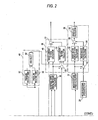
- a section in the controller C which is related to the left front wheel disc brake BA includes:
- the target fluid amount operating module 31 and the actual fluid amount operating module 32 calculates fluid amounts according to hydraulic pressures by following a preset map as shown in Fig. 3 .
- the actual differential pressure operating module 33 detects a differential pressure between before and after each of the regulator valve 7, the inlet valve 9 and the outlet valve 14 of the hydraulic pressure control unit 5, and when the hydraulic pressure in the hydraulic pressure path 6 is adjusted by the regulator valve 7 while keeping the inlet valve 9 and the outlet valve 14 opened and closed, respectively, the output hydraulic pressure of the master cylinder M which is detected by the master cylinder output hydraulic pressure detector 22 and the higher hydraulic pressure of the brake hydraulic pressures of the left front wheel disc brake BA and the right rear wheel disc brake BB which are detected by the brake hydraulic pressure detectors 23, 24 are inputted into the actual differential pressure operating module 33, and the actual differential pressure operating module 33 calculates an actual differential pressure between before and after the regulator valve 7.
- the actual differential pressure operating module 33 calculates an actual differential pressure between before and after each of the inlet valve 9 and the outlet valve 14.
- the target flow rate calculating unit 34 includes:
- the hydraulic pressure control unit target controlled variable setting unit 35 includes:
- control mode operating module 45 switches the control mode to the pressure build-up mode, the pressure reducing mode or to the pressure holding mode based on the sign and absolute value of the target flow rate obtained in the target flow rate calculating unit 34.
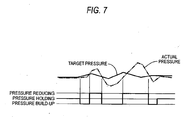
- target flow rate changes as shown in Fig.
- the control mode when a positive side value of the target flow rate surpasses a pressure-build up threshold, the control mode is shifted to the pressure build-up mode, when the positive side value becomes equal to or less than the pressure build-up threshold, the control mode is shifted from the pressure build-up mode to the pressure holding mode, while when a negative side value of the target flow rate becomes less than a pressure reducing threshold, the control mode is shifted from the pressure reducing mode to the pressure holding mode, and when the negative side value of the target flow rate becomes equal to or more than the pressure reducing threshold, the control mode is shifted from the pressure reducing mode to the pressure holding mode.
- the conventional one as shown in Fig.
- the control mode is shifted to the pressure build-up mode in response to the actual pressure becoming less than the pressure build-up threshold which is set lower than the target pressure, the control mode is shifted from the pressure build-up mode to the pressure holding mode in response to the actual pressure becoming equal to or more than the pressure build-up threshold, the control mode is shifted from the pressure holding mode to the pressure reducing mode in response to the actual pressure surpassing the pressure reducing threshold which is set higher than the target pressure, and furthermore, the control mode is shifted from the pressure reducing mode to the pressure holding mode in response to the actual pressure becoming equal to or less than the pressure reducing threshold.
- the actual pressure can be changed in a linear manner with no direct reference to the magnitude of the actual and target hydraulic pressures, whereby the control accuracy can be made compatible with the response.
- control current calculating unit 38 includes:
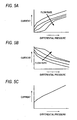
- the control current for controlling in a linear manner the regulator valve 7, the inlet valve 9 or the outlet valve 14, which is the linear solenoid valve is in general made to be obtained through typical table searches for differential pressure - current characteristics shown in Fig. 5(c) which are associated with flow rate, the characteristics of the linear solenoid valve are such as to change with flow rate, and the response is affected largely by the F/F control.
- the target current F/F term operating module 48 is made to obtain a control current by following a pre set characteristic map of differential pressure - flow rate - current using the target valve flow rate obtained by the valve flow rate operating module 46.
- the target current F/F term operating module 48 obtains a control current for the regulator valve 7 and the inlet valve 9 by following a characteristic map of differential pressure - flow rate - current as shown in Fig. 5 (a) in which with differential pressure remaining constant, current decreases as flow rate increases, and the target current F/F term operating module 48 obtains a control current for the outlet valve 14 by following a characteristic map of differential pressure - flow rate - current as shown in Fig. 5(b) in which with the differential pressure remaining constant, current increases as flow rate increases.
- control current for the regulator valve 7, the inlet valve 9 or the outlet valve 14 is determined based on the difference between the hydraulic pressure detected in the brake hydraulic pressure detector 23 and the target pressure which is set in target wheel brake pressure setting module 30 and the target flow rate obtained in the target flow rate calculating unit 34, and the regulator valve 7, the inlet valve 9 or the outlet valve 14 is controlled in a linear manner by the control current so determined.
- the target rotational speed operating module 37 calculates a target rotational speed for the electric motor 17 based on the target discharge amount for the pump which is obtained in the target discharge amount operating module 47 in the hydraulic pressure control unit target controlled variable setting unit 35.
- the drive duty calculating unit 39 includes:
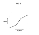
- the F/B gain in the operation in the target current F/B term operating module 50 is such as to change with the results of measuring the amount of time in the timer unit 40
- the timer unit 40 includes a pressure build-up timer 57 and a pressure reducing timer 58 which are adapted to count in response to a signal from the control mode operating module 45 of the hydraulic pressure control unit target controlled variable setting unit and a high select module 59 for high selecting count values of the pressure build-up timer 57 and the pressure reducing timer 58.
- the pressure build-up timer 57 implements counting up normally except when a count value is cleared to "0" when the hydraulic pressure control unit 5 is controlled to shift from the pressure build-up mode to the pressure reducing mode or to the pressure holding mode so as to obtain a count value TM_MDCAL_Z.
- the pressure reducing timer 58 implements counting up normally except when a count value is cleared to "0" when the hydraulic pressure control unit 5 is controlled to shift from the pressure reducing mode to the pressure build-up mode or to the pressure holding mode so as to obtain a count value TM_MDCAL_G.
- a high select value TM_MDCAL of those count values TM_MDCAL_Z and TM_MDCAL_G is obtained in the high select module 59.
- the high select value TM_MDCAL is inputted into the target current F/B term operating module 50 of the control current calculating unit 38 from the high select module 59 of the timer unit 40, and in the target current F/B term operating module 50, as shown in Fig. 9 , the F/B gain changes in such a manner as to increase as the high select value TM_MDCAL increases. Namely, when hunting is liable to be generated, the controlled variable of the regulator valve 7, the inlet valves 9, 10 or the outlet valves 14, 15 is increased by increasing the F/B gain, whereby the hydraulic pressure control is enabled without promoting vibrations. Moreover, since the F/B gain is not such as to be switched depending upon the existence of hunting but such as to change continuously with change in the high select value TM_MDCAL, a smooth hydraulic pressure control can be realized, and robustness is enhanced.
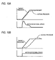
- the target rotational speed operating module 37 is such as to operate a target rotational speed for the electric motor 17 based on the target discharge mount of the pump 18 and the rotational speed of the electric motor 17 is controlled by operating the drive duty of the electric motor 17 by the drive duty calculating unit 39 based on the target rotational speed so operated, the response can be increased while maintaining quietness by reducing the operation noise, as shown in Fig. 10 (a) .
- optimizing the discharge amount of the pump 18 can contribute to increasing the hydraulic pressure control accuracy.
- the F/B gain is required to be increased in order to increase the controlled variable of the regulator valve 7.
- the self pressure build-up is implemented by adjusting the hydraulic pressure discharged from the pump 18 by the regulator valve 7, and in such a state that the discharge amount from the pump 18 has not yet reached a predetermined value in an initial stage of the control, there is no case where the pressure build-up is improved even by feedback on the regulator valve 7 side.
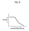
- the F/B gain is increased as shown in Fig.
- the rotational speed deviation (the target rotational speed obtained in the target rotational speed operating module 37 - the actual motor rotational speed) which is obtained in the summing point 53 of the drive duty calculating unit 39 is inputted into the target current F/B term operating module 48.
- the target current F/B term operating module 48 as shown in Fig.
- the switch 61 is closed to make the connection in the circuit, whereas the switch 62 is opened to break the connection, and when the electric motor 17 is braked, as shown in Fig. 13(b) , the switch 61 is opened to break the connection in the circuit, whereas the switch 62 is closed to make the connection, so that a motor brake state is obtained.
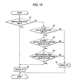
- step S1 whether or not the drive control mode of the electric motor 17 is an end mode is determined.
- drive modes for the electric motor 17 there are set modes of "stop,” “drive,” and “end.”
- the "end” mode denotes a state in which although there is no drive requirement, the electric motor 17 is rotating by virtue of inertia.
- step S1 If it is determined at step S1 that the drive control mode is not the end mode, the flow proceeds to step S3, where whether or not the drive control mode of the electric motor 17 is the drive mode is determined. If it is determined that the electric motor 17 is in the drive mode, then, whether or not the target motor voltage is a certain value or less is determined at step S4. If the target motor voltage is determined to be the certain value or less, then, whether or not the motor rotational speed deviation (the target rotational speed - the actual rotational speed) is a certain value or less is determined at step S5, and if the motor rotational speed deviation is the certain value of less, the flow proceeds from step S5 to step S2, where a brake-on state is produced.
- step S3 the flow proceeds from step S3 to step S6, where a brake-on state is produced. If it is determined at step S4 that although the drive control mode is the drive mode, the target motor voltage is exceeding a certain value. If it is determined at step S5 that although the drive control mode is the drive mode with the target motor voltage being the certain value or less, the motor rotational speed deviation is exceeding the certain value, a brake-off state is produced at step S6.
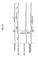
- the brake-on state is produced even when the drive control mode is the drive mode with the target motor voltage being the certain value of less and the motor rotational speed deviation being the certain value or less (namely, with the actual rotational speed of the electric motor 17 exceeding the target rotational speed beyond a predetermined value), whereby the deceleration response is increased.
- the controller C obtains target flow rates for the respective disc brakes BA, BB, ... in the target flow rate calculating unit 34 based on the target fluid amounts of the respective wheel disc brakes including the left front wheel disc brake BA and the right rear wheel disc brake BB which are obtained in the target fluid amount operating module 31 and the actual fluid amounts of the respective disc brakes BA, BB, ... which are obtained in the actual fluid amount operating module 32 based on the hydraulic pressures detected in the brake hydraulic pressure detectors 23, 24.
- the controller C also controls the operation of the hydraulic pressure control unit 5 based on the target flow rates so obtained. Therefore, the control accuracy and response in controlling the hydraulic pressures at the respective disc brakes BA, BB ... can be enhanced.
- the necessary response in controlling the hydraulic pressures at the respective disc brakes BA, BB ... is the ramp response, and now that it is understood that while the ramps are in response, brake fluid continues to be inputted into or outputted from the wheel brakes, by controlling the hydraulic pressures at the wheel brakes based on such continuous input or output of brake fluid, the control accuracy and response can be enhanced.
- the controller C controls the operation of the hydraulic pressure control unit 5 by switching the operation control mode to the pressure build-up mode, the pressure reducing mode or the pressure holding mode based on the signs and absolute values of the target flow rates which are obtained in the target flow rate calculating unit 34, the actual hydraulic pressures can be changed in a linear manner with no direct reference to the magnitude of the actual and target hydraulic pressures, whereby the control accuracy can be made compatible with the response.
- the current applied to the regulator valve 7, the inlet valves 9, 10 and the outlet valves 14, 15, which are the linear solenoid valves, in the hydraulic pressure control unit 5 is controlled based on the difference between the hydraulic pressures detected in the brake hydraulic pressure detectors 23, 24 and the target hydraulic pressures set in the target wheel brake pressure setting module 30 and the target flow rates obtained in the target flow rate calculating unit 34. Therefore, the control currents can be obtained in association with changes in the characteristics of the regulator valve 7, the inlet valves 9, 10 and the outlet valves 14, 15 with flow rate, thereby making it possible to enhance the control performance.
- the controller C is made to include the target discharge amount operating module 47 for obtaining a target discharge amount for the pump 18 based on the target flow rates obtained in the target flow rate calculating unit 34 and the target rotational speed operating module 37 for obtaining a target rotational speed for the electric motor 17 which drives the pump 18 based on the target discharge amounts obtained in the target discharge amount operating module 47 and controls the electric motor 17 based on the target rotational speed obtained in the target rotational speed operating module 37. Therefore, the response and quietness during the hydraulic pressure control can be enhanced and a further increase in hydraulic pressure control accuracy can be realized.
- controller C includes:
- the controller C controls the electric motor 17 so that the actual motor rotational speed detected by the motor rotational speed detecting module 29 becomes the target rotational speed operated in the target rotational speed operating module 37
- the F/B gain which controls the regulator valve 7 changes in such a manner as to become smaller than when the rotational speed deviation is small, whereby the F/B gain or controlled variable of the regulator valve 7 is made to become small in unnecessary portions so that the generation of overshoot can be suppressed even when the discharge amount of the pump 18 reaches the predetermined value at the initial stage of the control
- the rotational speed deviation the target rotational speed - the actual rotational speed
- the F/B gain is made to become large to increase the controlled variable of the regulator valve 7, whereby the response and toughness with respect to disturbance can be enhanced.
Landscapes
- Physics & Mathematics (AREA)
- Engineering & Computer Science (AREA)
- Fluid Mechanics (AREA)
- Transportation (AREA)
- Mechanical Engineering (AREA)
- Electromagnetism (AREA)
- Regulating Braking Force (AREA)
Claims (9)
- Système de commande de pression hydraulique pour frein de véhicule, comprenant :une source de génération de pression hydraulique (M) qui fournit une pression hydraulique en réponse à l'actionnement d'une pédale de frein ;des freins de roue (BA, BB) qui fonctionnent grâce à l'application d'une pression hydraulique ;une pompe (18) entraînée par un moteur électrique (17) ;une unité de détection de vitesse de rotation de moteur (29) qui détecte une vitesse de rotation du moteur électrique (17) ;une unité de réglage de vitesse de rotation cible (37) qui établit une vitesse de rotation cible pour le moteur électrique (17) ;une voie principale de pression hydraulique qui met en communication la source de génération de pression hydraulique (M) et la pompe (18) ;une sous-voie de pression hydraulique (6) qui met en communication la voie principale de pression hydraulique et les freins de roue (BA, BB) ;une électrovanne normalement ouverte (7) interposée entre la sous-voie de pression hydraulique (6) et la source de génération de pression hydraulique (M) ;une unité de détection de pression hydraulique de frein (23, 24) qui détecte des pressions hydrauliques au niveau des freins de roue (BA, BB) ;une unité de réglage de pression de frein de roue cible (30) qui règle des pressions hydrauliques cibles pour les freins de roue (BA, BB) ; etune unité de commande (C) qui commande le moteur électrique (17) de sorte que la vitesse de rotation détectée par l'unité de détection de vitesse de rotation de moteur (29) devient la vitesse de rotation cible et commande également l'électrovanne normalement ouverte (7) de sorte que les pressions hydrauliques dans les freins de roue (BA, BB) deviennent la pression hydraulique de freins de roue cibles,dans lequel l'unité de commande réduit une quantité de commande de l'électrovanne normalement ouverte (7) à mesure qu'un écart entre la vitesse de rotation détectée et la vitesse de rotation cible du moteur électrique (17) augmente.
- Système de commande de pression hydraulique pour frein de véhicule selon la revendication 1, comprenant en outre :une unité de soupape de commutation (25) comprenant :des soupapes d'entrée (9, 10) disposées entre la sous-voie de pression hydraulique (6) et les freins de roue (BA, BB) ; etdes soupapes de sortie (14, 15) disposées entre les freins de roue (BA, BB) et un réservoir (13),où l'unité de soupape de commutation (25) assure une commutation entre les modes suivantes :un mode d'accumulation de pression dans lequel les soupapes d'entrée (9, 10) sont ouvertes et les soupapes de sortie (14, 15) sont fermées ;un mode de réduction de pression dans lequel les soupapes d'entrée (9, 10) sont fermées et les soupapes de sortie (14, 15) sont ouvertes, etun mode de maintien de pression dans lequel les soupapes d'entrée et de sortie (9, 10, 14, 15) sont fermées.
- Système de commande de pression hydraulique pour frein de véhicule selon la revendication 2, dans lequel l'unité de commande (C) comprend en outre :une unité de calcul de quantité de fluide cible (31) qui calcule la quantité de fluide cible à partir de la pression hydraulique cible établie par l'unité de réglage de pression hydraulique de frein de roue (30) ;une unité de calcul de quantité de fluide effective (32) qui calcule une quantité de fluide effective à partir de la pression hydraulique détectée par l'unité de détection de pression hydraulique (23, 24) ; etune section de calcul de taux de débit cible (34) qui calcule un débit de taux cible pour les freins de roue (BA, BB) à partir de la quantité de fluide cible et de la quantité de fluide effective.
- Système de commande de pression hydraulique pour frein de véhicule selon la revendication 3, dans lequell'unité de commande (C) assure une commutation entre le mode d'accumulation de pression, le mode de réduction de pression et le mode de maintien de pression à partir de signes et de valeurs absolues des taux de débits cibles calculés dans l'unité de calcul de taux de débit cible (34).
- Système de commande de pression hydraulique pour frein de véhicule selon la revendication 4, dans lequell'unité de commande (C) commande des courants appliqués à l'électrovanne normalement ouverte (7), aux soupapes d'entrée (9, 10) et aux soupapes de sortie (14, 15) à partir du taux de débit cible et d'une différence entre les pressions hydrauliques détectées par l'unité de détection de pression hydraulique de frein (23, 24) et les pressions hydrauliques cibles.
- Système de commande de pression hydraulique pour frein de véhicule selon la revendication 1, dans lequell'unité de commande (C) comprend en outre une unité de calcul de quantité de décharge cible (47) qui calcule une quantité de décharge cible pour la pompe (18) à partir du taux du débit cible, etl'unité de réglage de vitesse de rotation cible (37) établit la vitesse de rotation cible à partir de la quantité de décharge cible.
- Système de commande de pression hydraulique pour frein de véhicule selon la revendication 2, dans lequell'unité de commande (C) comprend en outre :une minuterie d'accumulation de pression (57) qui met en oeuvre une valeur de comptage à la hausse normalement, sauf quand la valeur de comptage est remise à « 0 » lorsque l'unité de commande (C) commande le passage du mode d'accumulation de pression au mode de réduction de pression ou au mode de maintien de pression ;une minuterie de réduction de pression (58) qui met en oeuvre la valeur de comptage à la hausse normalement, sauf quand la valeur de comptage est remise à « 0 » lorsque l'unité de commande (C) commande le passage du mode de réduction de pression au mode d'accumulation de pression ou au mode de maintien de pression ; etune unité de sélection haute (59) qui sélectionne une valeur de sélection haute (TM_MDCAL) à partir des valeurs de comptage de la minuterie d'accumulation de pression (57) et de la minuterie de réduction de pression (58),dans lequel l'unité de commande (C) augmente une variable de commande de l'électrovanne normalement ouverte (7), des soupapes d'entrée (9, 10) ou des soupapes de sortie (14, 15) à mesure que la valeur de sélection haute (TM_MDCAL) augmente.
- Système de commande de pression hydraulique pour frein de véhicule selon la revendication 1, dans lequell'unité de commande (C) modifie un gain (F/B) qui commande l'électrovanne normalement ouverte (7) de façon à réduire une quantité de commande de l'électrovanne normalement ouverte (7) à mesure que l'écart entre la vitesse de rotation détectée et la vitesse de rotation cible augmente.
- Système de commande de pression hydraulique pour frein de véhicule selon la revendication 1, dans lequelune batterie (60) et un premier commutateur (61) forment un circuit série, et dans lequel ce circuit série et un second commutateur (62) pour établir un court-circuit entre les deux bornes du moteur électrique (17) sont connectés aux deux bornes du moteur électrique (17) en parallèle.
Applications Claiming Priority (1)
| Application Number | Priority Date | Filing Date | Title |
|---|---|---|---|
| JP2007148565A JP4949934B2 (ja) | 2007-06-04 | 2007-06-04 | 車両用ブレーキ液圧制御装置 |
Publications (2)
| Publication Number | Publication Date |
|---|---|
| EP2000375A1 EP2000375A1 (fr) | 2008-12-10 |
| EP2000375B1 true EP2000375B1 (fr) | 2009-09-23 |
Family
ID=39709004
Family Applications (1)
| Application Number | Title | Priority Date | Filing Date |
|---|---|---|---|
| EP08010197A Ceased EP2000375B1 (fr) | 2007-06-04 | 2008-06-04 | Système de commande de pression hydraulique pour frein de véhicule |
Country Status (4)
| Country | Link |
|---|---|
| US (1) | US7976108B2 (fr) |
| EP (1) | EP2000375B1 (fr) |
| JP (1) | JP4949934B2 (fr) |
| DE (1) | DE602008000162D1 (fr) |
Families Citing this family (7)
| Publication number | Priority date | Publication date | Assignee | Title |
|---|---|---|---|---|
| JP5321885B2 (ja) * | 2008-03-31 | 2013-10-23 | 株式会社アドヴィックス | 制動制御装置 |
| US8573714B2 (en) | 2009-02-06 | 2013-11-05 | Toyota Jidosha Kabushiki Kaisha | Brake device |
| DE102011078890A1 (de) * | 2011-07-08 | 2013-01-10 | Robert Bosch Gmbh | Überwachungsvorrichtung für zumindest eine Untereinheit eines hydraulischen Bremssystems und Verfahren zum Untersuchen einer Funktionsfähigkeit zumindest einer Untereinheit eines hydraulischen Bremssystems |
| DE102013203594A1 (de) * | 2012-03-06 | 2013-09-12 | Continental Teves Ag & Co. Ohg | Verfahren zum Betreiben einer Bremsanlage für Kraftfahrzeuge sowie Bremsanlage |
| JP5563004B2 (ja) * | 2012-03-28 | 2014-07-30 | 日信工業株式会社 | 車両用ブレーキ液圧制御装置 |
| JP6069149B2 (ja) * | 2013-09-19 | 2017-02-01 | 日立オートモティブシステムズ株式会社 | ブレーキ制御装置 |
| JP7070145B2 (ja) * | 2018-06-25 | 2022-05-18 | 株式会社アドヴィックス | 車両の制動制御装置 |
Family Cites Families (12)
| Publication number | Priority date | Publication date | Assignee | Title |
|---|---|---|---|---|
| EP1077847B1 (fr) | 1998-05-12 | 2003-03-05 | Continental Teves AG & Co. oHG | Systeme de freinage hydraulique pour freinages regules et confortables |
| DE19953627B4 (de) * | 1998-11-09 | 2020-08-20 | Kelsey-Hayes Co. | Closed-Loop-Drehzahlregelung eines ABS-Pumpenmotors mit variablem Arbeitszyklus und variabler Frequenz |
| JP4934937B2 (ja) * | 2001-01-31 | 2012-05-23 | 株式会社デンソー | 車両用ブレーキ装置 |
| DE10341027A1 (de) | 2002-09-06 | 2004-03-25 | Continental Teves Ag & Co. Ohg | Verfahren und Vorrichtung zur Regelung einer Bremsanlage für Kraftfahrzeuge |
| JP4210515B2 (ja) | 2002-12-20 | 2009-01-21 | 本田技研工業株式会社 | 車両用アンチロックブレーキ制御装置 |
| JP2005329892A (ja) * | 2004-05-21 | 2005-12-02 | Hitachi Ltd | ブレーキ制御装置 |
| DE102004045391A1 (de) * | 2004-09-18 | 2006-03-23 | Robert Bosch Gmbh | Verfahren zur Steuerung oder Regelung eines elektronisch ansteuerbaren, nach dem Rückförderprinzip arbeitenden Fahrzeugbremssystems und elektronisch ansteuerbares, nach dem Rückförderprinzip arbeitendes Fahrzeugbremssystem |
| US7568773B2 (en) * | 2005-07-19 | 2009-08-04 | Nissin Kogyo Co., Ltd. | Brake fluid pressure controller for vehicle |
| JP2007050742A (ja) * | 2005-08-17 | 2007-03-01 | Hitachi Ltd | 車両の制動制御装置 |
| JP5119646B2 (ja) * | 2006-03-06 | 2013-01-16 | 株式会社アドヴィックス | 車両用ブレーキ制御装置 |
| JP4618169B2 (ja) * | 2006-03-13 | 2011-01-26 | 株式会社アドヴィックス | 車両用ブレーキ制御装置 |
| JP4974766B2 (ja) * | 2007-05-30 | 2012-07-11 | 本田技研工業株式会社 | 車両用ブレーキ液圧制御装置 |
-
2007
- 2007-06-04 JP JP2007148565A patent/JP4949934B2/ja not_active Expired - Fee Related
-
2008
- 2008-06-03 US US12/132,190 patent/US7976108B2/en not_active Expired - Fee Related
- 2008-06-04 EP EP08010197A patent/EP2000375B1/fr not_active Ceased
- 2008-06-04 DE DE602008000162T patent/DE602008000162D1/de active Active
Also Published As
| Publication number | Publication date |
|---|---|
| JP4949934B2 (ja) | 2012-06-13 |
| US7976108B2 (en) | 2011-07-12 |
| DE602008000162D1 (de) | 2009-11-05 |
| EP2000375A1 (fr) | 2008-12-10 |
| JP2008296884A (ja) | 2008-12-11 |
| US20080296967A1 (en) | 2008-12-04 |
Similar Documents
| Publication | Publication Date | Title |
|---|---|---|
| EP1997701B1 (fr) | Système de contrôle de pression hydraulique pour frein de véhicule | |
| EP2000375B1 (fr) | Système de commande de pression hydraulique pour frein de véhicule | |
| EP3000673A1 (fr) | Dispositif de frein | |
| US8210620B2 (en) | Braking force control system for vehicles | |
| US8544963B2 (en) | Braking control apparatus | |
| US6739676B1 (en) | Braking system having vacuum booster whose boosting ratio is lowered at fixed transition point at which wheel cylinder pressure increase is initiated | |
| JP3287259B2 (ja) | 制動力制御装置 | |
| US20040080208A1 (en) | Method and control system for controlling an electronically regulated brake actuating system | |
| EP0425261B1 (fr) | Procédé de commande de pression hydraulique de freinage pour véhicule | |
| US6612662B2 (en) | Anti-skid control system for automotive vehicle | |
| EP1795415B1 (fr) | Dispositif de freinage pour véhicule automobile | |
| JP2006312384A (ja) | 車両の回生制動および摩擦制動装置 | |
| US6217133B1 (en) | Brake force control apparatus | |
| US8155855B2 (en) | Vehicle motion control apparatus | |
| CN106364470B (zh) | 车辆用制动装置 | |
| JP3617180B2 (ja) | 制動力制御装置 | |
| JP4987575B2 (ja) | 車両用ブレーキ液圧制御装置 | |
| JP4667399B2 (ja) | ブレーキ制御装置 | |
| JP4555746B2 (ja) | 車両用ブレーキ液圧制御装置 | |
| JP4717503B2 (ja) | 車両用ブレーキ装置 | |
| JP4953925B2 (ja) | 車両のアンチロックブレーキ制御装置 | |
| JP4590301B2 (ja) | 車両用ブレーキ制御装置 | |
| US5367461A (en) | Variably sensitive traction control method for vehicle | |
| JP2008302717A (ja) | 車両のアンチロックブレーキ制御装置 | |
| JPH08268256A (ja) | ブレーキ制御装置 |
Legal Events
| Date | Code | Title | Description |
|---|---|---|---|
| PUAI | Public reference made under article 153(3) epc to a published international application that has entered the european phase |
Free format text: ORIGINAL CODE: 0009012 |
|
| 17P | Request for examination filed |
Effective date: 20080604 |
|
| AK | Designated contracting states |
Kind code of ref document: A1 Designated state(s): AT BE BG CH CY CZ DE DK EE ES FI FR GB GR HR HU IE IS IT LI LT LU LV MC MT NL NO PL PT RO SE SI SK TR |
|
| AX | Request for extension of the european patent |
Extension state: AL BA MK RS |
|
| 17Q | First examination report despatched |
Effective date: 20090115 |
|
| GRAP | Despatch of communication of intention to grant a patent |
Free format text: ORIGINAL CODE: EPIDOSNIGR1 |
|
| GRAS | Grant fee paid |
Free format text: ORIGINAL CODE: EPIDOSNIGR3 |
|
| AKX | Designation fees paid |
Designated state(s): DE GB |
|
| GRAA | (expected) grant |
Free format text: ORIGINAL CODE: 0009210 |
|
| RAP1 | Party data changed (applicant data changed or rights of an application transferred) |
Owner name: HONDA MOTOR CO., LTD. |
|
| AK | Designated contracting states |
Kind code of ref document: B1 Designated state(s): DE GB |
|
| REG | Reference to a national code |
Ref country code: GB Ref legal event code: FG4D |
|
| REF | Corresponds to: |
Ref document number: 602008000162 Country of ref document: DE Date of ref document: 20091105 Kind code of ref document: P |
|
| PLBE | No opposition filed within time limit |
Free format text: ORIGINAL CODE: 0009261 |
|
| STAA | Information on the status of an ep patent application or granted ep patent |
Free format text: STATUS: NO OPPOSITION FILED WITHIN TIME LIMIT |
|
| 26N | No opposition filed |
Effective date: 20100624 |
|
| PGFP | Annual fee paid to national office [announced via postgrant information from national office to epo] |
Ref country code: GB Payment date: 20130529 Year of fee payment: 6 |
|
| GBPC | Gb: european patent ceased through non-payment of renewal fee |
Effective date: 20140604 |
|
| PG25 | Lapsed in a contracting state [announced via postgrant information from national office to epo] |
Ref country code: GB Free format text: LAPSE BECAUSE OF NON-PAYMENT OF DUE FEES Effective date: 20140604 |
|
| PGFP | Annual fee paid to national office [announced via postgrant information from national office to epo] |
Ref country code: DE Payment date: 20150527 Year of fee payment: 8 |
|
| REG | Reference to a national code |
Ref country code: DE Ref legal event code: R119 Ref document number: 602008000162 Country of ref document: DE |
|
| PG25 | Lapsed in a contracting state [announced via postgrant information from national office to epo] |
Ref country code: DE Free format text: LAPSE BECAUSE OF NON-PAYMENT OF DUE FEES Effective date: 20170103 |