EP2000363A2 - Stützstruktur für die Bodenplatte eines Gepäckraums - Google Patents
Stützstruktur für die Bodenplatte eines Gepäckraums Download PDFInfo
- Publication number
- EP2000363A2 EP2000363A2 EP08005037A EP08005037A EP2000363A2 EP 2000363 A2 EP2000363 A2 EP 2000363A2 EP 08005037 A EP08005037 A EP 08005037A EP 08005037 A EP08005037 A EP 08005037A EP 2000363 A2 EP2000363 A2 EP 2000363A2
- Authority
- EP
- European Patent Office
- Prior art keywords
- floor panel
- guide part
- guide
- pin members
- pin
- Prior art date
- Legal status (The legal status is an assumption and is not a legal conclusion. Google has not performed a legal analysis and makes no representation as to the accuracy of the status listed.)
- Granted
Links
Images


Classifications
-
- B—PERFORMING OPERATIONS; TRANSPORTING
- B60—VEHICLES IN GENERAL
- B60R—VEHICLES, VEHICLE FITTINGS, OR VEHICLE PARTS, NOT OTHERWISE PROVIDED FOR
- B60R11/00—Arrangements for holding or mounting articles, not otherwise provided for
-
- B—PERFORMING OPERATIONS; TRANSPORTING
- B60—VEHICLES IN GENERAL
- B60R—VEHICLES, VEHICLE FITTINGS, OR VEHICLE PARTS, NOT OTHERWISE PROVIDED FOR
- B60R5/00—Compartments within vehicle body primarily intended or sufficiently spacious for trunks, suit-cases, or the like
- B60R5/04—Compartments within vehicle body primarily intended or sufficiently spacious for trunks, suit-cases, or the like arranged at rear of vehicle
Definitions
- the present invention relates to a support structure of a floor panel of a luggage room located at a rear portion of a vehicle.
- a divider board which is set in a height position substantially flush with the floor surface, and the space above this divider board can be utilized as a trunk room.
- This structure is widely applied to a rear luggage room for a passenger vehicle which has little sufficient space.
- it is also performed to divide a midway portion in the up and down direction of rear space of the rearmost row seat up and down with a so-called tonneau cover in order to utilize the rear space.
- the luggage room space is thus divided up and down with the divider board, if it is possible to adjust the height of the divider board by changing the position in the up-down direction in accordance with the shape or size of a luggage to be accommodated in each compartmental space, or so that the luggage room floor surface can be flattened or so that a flat floor can be realized when the rearmost row seat is collapsed, effective utilization of the space according to the kind of luggage is possible and usability of the luggage room becomes good, whereby convenience can be heightened.
- Patent Document 1 the following constitution has been disclosed: a pin member protruding in the vehicle width direction is provided for a divider board which divides luggage room space up and down; an upper groove part and a lower groove part which engage with this pin member, and a coupling groove part which couples the both groove parts are formed in an interior member located in the vehicle width direction; the pin member is engaged with the upper groove part thereby to hold the divider board in a position where the divider board is flattened with the luggage room floor surface; and the pin member is engaged with the lower groove part thereby to move down the position of the divider board and widen the luggage room space.
- Patent Document 2 the following constitution has been disclosed: plural roller elements are provided on a side surface of a divider board which divides luggage space up and down; an upper groove part, a lower groove part and a coupling groove part which couples the both groove parts in which these roller elements can move are formed in an interior member located in the vehicle width direction; and the divider board is slid and moved thereby to locate the roller elements in the upper groove part or the lower groove part through the coupling groove part, whereby the divider board can be moved above the luggage room floor surface.
- a support structure of a floor panel of a luggage room of a vehicle the support structure for positioning the floor panel in a upper step position and a lower step position, the support structure comprising:
- the first and second pin members which are spaced in a longitudinal direction of the vehicle, support the floor panel, support stability increases, and the sway in the width direction or in the longitudinal direction can be reduced. Further, the load of the floor panel can be distributed to the first and second pin members, so that support rigidity can be improved by simple constitution. Further, since there is no guide member which opens and closes unlike the conventional constitution, there is no fear that operational disadvantage of the opening and closing part occurs. Therefore, though the constitution is simplified, the up-down operation of the floor panel can be smoothly performed by the pivoting and sliding operations of the pin members. Further, since the floor panel can be pivoted upward from the lower step position, the moving amount in the longitudinal direction of the floor panel can be reduced. Accordingly, this support structure can be applied in the wide range.
- Each of the guides may include a fifth guide part, adapted to regulate a position of the one of the second pin members guided by the first guide part.
- the second guide part may be continuously connected to the fifth guide part and is extended toward rear side and obliquely upper side of the vehicle.
- each of the second pin members can shift in the second guide part smoothly, and the moving operation of the floor panel after the upward pivoting operation of the floor panel from the lower step position becomes smooth, so that operability can be more heightened.
- Each of the guides may include a sixth guide part, adapted to regulate a position of the one of the first pin members guided by the third guide part.
- the fourth guide part may be continuously connected to the sixth guide part.
- each of the first pin members can shift in the fourth guide part smoothly, and the moving operation of the floor panel after the pivoting operation about the second pin members becomes smooth, so that the operability can be more heightened.
- the second guide part may be continuously connected to the first guide part.
- the fourth guide part may be continuously connected to the third guide part.
- the second guide part may include a guide groove defined by a pair of surfaces which are continuously connected to the first guide part and the fifth guide part, respectively and which are opposed to each other.
- the second guide part as the groove
- the second pin members can be surely guided.
- the first guide part and the fifth guide part not as grooves but as only guide surfaces, the both side surfaces of the luggage room are not subjected to more processing than they need, so that processing cost is suppressed.
- the guide part is constituted not by the groove but by only the surface, the degree of freedom in the second pin member improves thereby to enable the smooth movement of the second pin member, and the both side surfaces of the luggage room are neat and have good appearance.
- the fourth guide part may include a guide groove defined by a pair of surfaces which are continuously connected to the third guide part and the sixth guide part, respectively and which are opposed to each other.
- the fourth guide part as the groove
- the first pin members can be surely guided.
- the third guide part and the sixth guide part not as grooves but as only guide surfaces, the both side surfaces of the luggage room are not subjected to more processing than they need, so that processing cost is suppressed.
- the guide part is constituted not by the groove but by only the surface, the degree of freedom in the first pin member improves thereby to enable the smooth movement of the first pin member, and the both side surfaces of the luggage room are neat and have good appearance.
- the support structure may further comprise: an operational part for moving the floor panel in the direction, disposed at a rear portion of the floor panel.
- the first pin members may be disposed at front portions of the floor panel.
- a leading end of the floor panel does not lower downward at more level than it needs in the upward pivoting operation, and the second pin members can be arranged as to the front as possible. Therefore, the pivoting operation about the pin members can be performed by small force, utilizing the principle of the lever, so that operability can be more heightened.
- a support structure of a floor panel of a luggage room of a vehicle which includes: first pin members protruding from both sides of the floor panel in a width direction; second pin members protruding from the sides of the floor panel and disposed at rear side of the first pin members; and guides respectively formed on both side surfaces of the luggage room which are opposed to the first and second pin members.
- Each of the guides includes: a first guide part guiding the second pin member so that the floor panel can be pivoted, from the lower step position, about the first pin member or about a position located at front side of the first pin member; a second guide part guiding the second pin member toward rear side of the vehicle; a third guide part guiding the first pin member, when the second pin member is located at a rear end of the second guide part, so that the floor panel can be pivoted about the second pin member; and a fourth guide part guiding the first pin member toward front side of the vehicle to arrange the floor panel in the upper step position.
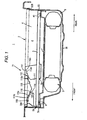
- a floor panel 3 constituting a floor surface 2 of a luggage room 1 located at a rear part of a vehicle can be moved to an upper step position and to a lower step position as shown in Fig. 1 .
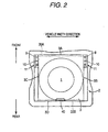
- two steps of portions 4 (hollowed parts 4) hollowed toward the downside of a vehicle body are formed by a surrounding panel 30.
- a downmost portion of the hollowed part 4 is used as a housing space 6 in which a spare tire is housed.
- a floor under-tray 7 is arranged on the housing space 6 thereby to form a housing space 8. In the embodiment, the floor under-tray 7 divides the housing space 6 from the housing space 8.
- reception parts 30A and 30B are formed, on which a front end 3A which is a vehicle front portion of the floor panel 3 and a rear end 3D which is a vehicle rear portion of the floor panel 3 when the floor panel 3 is positioned in the upper step position, are placed respectively.
- This hollowed part 4 is stopped up (covered) by the floor panel 3 retained horizontally in the upper step position which is substantially flush with the floor surface 2 shown by chain double-dashed lines in Fig. 1 . Further, the hollowed part 4 is opened when the floor panel 3 is positioned in the lower step position where the floor panel 3 is horizontally placed on the floor under-tray 7, whereby a space can be enlarged. At a leading end of the floor under-tray 7, a step portion 7A is formed, which is lower in level than the placement surface of the floor panel 3.
- the floor panel 3 has a size at which the floor panel 3 can cover the whole of the hollowed part 4.
- a pair of first pin members 9 and a pair of second pin members 10 which protrude in a width direction of the vehicle are disposed at both side portions 3B, 3C of the floor panel 3 on a leading end 3A thereof.
- Each pin member 9 and each pin member 10 are spaced in a longitudinal direction of the vehicle (in a front-rear direction).
- the first pin members 9 are disposed at vehicle front side
- the second pin members 10 are disposed more rearward than the first pin members 9.
- an operational part 40 for operating the floor panel 3 in a vertical direction (up-down direction) is formed.
- Guide parts 11 are respectively provided on side surfaces of the hollowed part 4, which are both side surfaces of the luggage room 1, opposed to each pin member 9, 10.
- the guide parts 11 are engaged with the pin members 9, 10 thereby to guide the floor panel 3 in the up-down direction.
- the first pin members 9 are front-side pins
- the second pin members 10 are rear-side pins.
- the first pin members 9 and the second pin members 10 have the same shape and the same function on the right and the left.
- the guide parts 11 have the same constitution in side view and the same function. Therefore, using one of the first pin members 9, one of the second pin members 10 and one of the guide parts 11, the constitution and operation of a support mechanism will be described below.
- the guide part 11 includes, as shown in Fig. 1 , a first guide surface 111, a second pin guide groove 112 (hereinafter described as a "guide groove 112"), a third guide surface 113, a first pin guide groove 114 (hereinafter described as a "guide groove 114"), a fifth guide surface 115, and a sixth guide surface 116.
- the first guide surface (first guide part) 111 guides the second pin member 10 so that the floor panel 3 can be pivoted from the lower step position below the floor surface 2 about the first pin member 9 or about the vehicle front position which is located more forward than a position at which the first pin member 9 is disposed.
- the guide groove (second guide part) 112 guides the second pin member 10 guided by the first guide surface 111 toward the rear side of the vehicle.
- the third guide surface (third guide part) 113 when the second pin member 10 is located at a rear end 112c of the guide groove 112, guides movement of the first pin member 9 so that the floor panel 3 can be pivoted about the second pin member 10.
- the guide groove (fourth guide part) 114 guides the first pin member 9 guided by the third guide surface 113 toward the front side of the vehicle thereby to locate the floor panel 3 in the upper step position.
- the fifth guide surface (fifth guide part) 115 regulates the pivoting position of the second pin member 10 guided by the first guide surface 111.
- the sixth guide surface (sixth guide part) 116 regulates the pivoting position of the first pin member 9 guided by the third guide surface 113.
- the guide groove 112 includes a pair of opposed surfaces 112a, 112b to each other, which are continuously connected to the first and fifth guide surfaces 111, 115, respectively.
- the guide groove 112 is extended toward obliquely upper side and rear side of the vehicle.
- a side of a rear end 112c of the guide groove 112 opens to the floor surface 2.
- a stopper part 117 which includes a substantially vertical surface, is formed in the vicinity of the rear end 112c. The stopper part 117 regulates the rearward movement of the second pin member 10 in the guide groove 112.
- the guide groove 114 includes a pair of opposed surfaces 114a, 114b to each other, which are continuously connected to the third and sixth guide surfaces 113, 116, respectively.
- a space part 118 is formed which houses the first pin member 9 therein when the floor panel 3 is positioned the upper step position.
- the first pin members 9 and the second pin members 10 which protrude in the width direction of the vehicle are provided at the side parts 3B, 3C of the leading end 3A of the floor panel 3.
- the first pin members 9 and the second pin members 10 are spaced in the longitudinal direction of the vehicle.
- the guide parts 11 are formed on the side surfaces of the hollowed part 4 and are opposed to these pin members 9 and 10.
- the guide parts 11 are engaged with the respective pin members 9, 10, thereby to guide the floor panel 3 in the up-down direction.
- the guide parts 11 are enable the movements of the floor panel 3 to the upper step position and to the lower step position.
- the present invention can be applied not only to the support structure of the floor panel 3 under the floor surface 2 as in this embodiment, but also to a support structure in which the floor panel 3 is set at a position which is more upward than the upper step position of the floor surface 2.
- the floor panel 3 As shown in Fig. 3 , when the operator lifts the operational part 40 located at the rear end 3D of the floor panel 3 located in the lower step position which is more downward than the floor surface 2, the floor panel 3, as shown by chain double-dashed lines in Fig. 3 , is lifted centered at its leading end 3A. At this time, the second pin member 10 is guided pivotably toward the front side of the vehicle by the first guide surface 111. At the leading end of the floor under-tray 7, the step portion 7A is formed, which is lower in level than the placement surface of the floor panel 3.
- the leading end 3A enters the inside of the step 7A, so that the position of the leading end 3A, that is, the rising fulcrum position of the floor panel 3 becomes stable, and lifting is smoothly performed.
- the second pin member 10 comes into contact with the fifth guide surface 115, whereby pivoting in the opening direction is regulated.
- the operator changes the pivoting operation of the floor panel 3 in the upward direction, to the moving operation of the floor panel 3 toward the rear side of the vehicle.
- the second pin member 10 moves along the fifth guide surface 115, and introduced in the guide groove 112, as shown in Fig. 4 . Since the fifth guide surface 115 and the guide groove 112 are continuously connected to each other, the pivoting operation in the upward direction from the lower step position, and the moving operation in the rearward direction are smoothly guided in continuity, whereby the operability can be more heightened.
- the floor panel 3 intends to be pivoted by its weight about the second pin member 10 in a direction in which a side of the rear end 3D is moved down.
- the third guide surface 113 is formed so as to enable the pivoting operation of the floor panel 3 about the second pin member 10, it enables the downward pivoting operation of the floor panel 3 about the second pin member 10 without obstructing the movement of the first pin member 9.
- the first pin member 9 comes into contact with the sixth guide surface 116, whereby pivoting in the downward direction of the floor panel 3 about the second pin member 10 is regulated.
- the guide groove 114 and the sixth guide surface 116 are continuously connected to each other, the first pin member 9 can smoothly shift into the guide groove 114, and the moving operation of the floor panel 3 after the pivoting operation about the second pin member 10 can be smoothly performed, whereby the operability can be more heightened.
- the floor panel 3 restarts the pivoting operation.
- the first pin member 9 is introduced into the guide groove 114 as shown in Fig. 5 , by the load of the floor panel 3 which is going down, the firs pin member 9 moves in the guide groove 114 obliquely upward in the forward direction, and the second pin member 10 moves into the guide groove 112 obliquely downward in the forward direction.
- the second guide part 112 is formed in the shape of a groove, it can surely guide the second pin member 10 toward the rear side. Since the fourth guide part 114 is also formed in the shape of a groove, it can surely guide the first pin member 9 toward the front side.
- the first guide part 111 and the fifth guide part 115 are not formed in the shape of a groove but constituted by only a surface, the side surfaces of the hollowed part 4 are not subjected to more processing than they need, so that processing cost is suppressed.
- the guide part is constituted not by the groove but by only the surface, the degree of freedom in the second pin member 10 improves. Therefore, the smooth movement is possible, and the side surfaces of the hollowed part 4 are neat and have good appearance.
- the third guide part 113 and the sixth guide part 116 are not formed in the shape of a groove but constituted by only a surface, the side surfaces of the hollowed part 4 are not subjected to more processing than they need, so that processing cost is suppressed.
- the guide part is constituted not by the groove but by only the surface, the degree of freedom in the first pin member 9 also improves, and the smooth movement is possible. Further, the side surfaces of the followed part 4 are neat and have good appearance.
- the leading end 3A of the floor panel 3 does not lower downward at more level than it needs in the upward pivoting operation.
- the second pin member 10 can be arranged as to the front as possible, the pivoting operation of the floor panel 3 about the second pin member 10 can be performed by small force, utilizing the principle of the lever, so that operability can be more heightened.
- an arcuate step portion 119 may be formed, as a stopper part, near the rear end 112c of the opposed surface 112a.
- each guide surface and each guide groove are formed as the guide part 11 by cutting the side surfaces of the hollowed part 4, a mode as shown in Fig. 7 may be adopted in which each guide surface and each guide groove are formed on two members 120, 130.
- the members 120, 130 are attached to the side surfaces of the hollowed part 4. Namely, as shown in Fig. 7 , the first guide surface 111, the opposed surface 112a, which constitute the guide groove 112, and the stopper surface 117 are formed on the member 120.
- the opposed surface 112b, which constitute the guide groove 112, the third guide surface 113, the guide groove 114 and the fifth guide surface 115 are formed on the member 130.
- the members 120, 130 are arranged so that the opposed surface 112a formed on the member 120 and the opposed surface 112b formed on the member 130 are opposed to each other, whereby the guide groove 112 is constituted.
Landscapes
- Engineering & Computer Science (AREA)
- Mechanical Engineering (AREA)
- Vehicle Step Arrangements And Article Storage (AREA)
- Body Structure For Vehicles (AREA)
Applications Claiming Priority (1)
| Application Number | Priority Date | Filing Date | Title |
|---|---|---|---|
| JP2007148282A JP4488028B2 (ja) | 2007-06-04 | 2007-06-04 | 荷室床板の支持構造 |
Publications (3)
| Publication Number | Publication Date |
|---|---|
| EP2000363A2 true EP2000363A2 (de) | 2008-12-10 |
| EP2000363A3 EP2000363A3 (de) | 2010-12-15 |
| EP2000363B1 EP2000363B1 (de) | 2014-12-10 |
Family
ID=39735187
Family Applications (1)
| Application Number | Title | Priority Date | Filing Date |
|---|---|---|---|
| EP20080005037 Ceased EP2000363B1 (de) | 2007-06-04 | 2008-03-18 | Stützstruktur für die Bodenplatte eines Gepäckraums |
Country Status (3)
| Country | Link |
|---|---|
| EP (1) | EP2000363B1 (de) |
| JP (1) | JP4488028B2 (de) |
| CN (1) | CN101318525B (de) |
Cited By (1)
| Publication number | Priority date | Publication date | Assignee | Title |
|---|---|---|---|---|
| ES2537931A1 (es) * | 2013-12-13 | 2015-06-15 | Seat, S.A. | Maletero con piso regulable para vehículo |
Families Citing this family (5)
| Publication number | Priority date | Publication date | Assignee | Title |
|---|---|---|---|---|
| JP5229080B2 (ja) * | 2009-04-08 | 2013-07-03 | 三菱自動車工業株式会社 | 車両の荷室構造 |
| JP4924732B2 (ja) * | 2009-07-06 | 2012-04-25 | 日産自動車株式会社 | スペアタイヤ設置構造 |
| JP5906715B2 (ja) * | 2011-12-20 | 2016-04-20 | 日産自動車株式会社 | 後部車体構造 |
| JP5924974B2 (ja) * | 2012-02-17 | 2016-05-25 | 日産自動車株式会社 | ラゲッジボードの移動機構 |
| CN110481442A (zh) * | 2019-08-29 | 2019-11-22 | 北京汽车股份有限公司 | 一种车辆 |
Citations (2)
| Publication number | Priority date | Publication date | Assignee | Title |
|---|---|---|---|---|
| JP2005219702A (ja) | 2004-02-09 | 2005-08-18 | Gp Daikyo Corp | 車両の仕切板支持機構 |
| US20060016840A1 (en) | 2004-07-21 | 2006-01-26 | Svenson Richard N | Adjustable shelf system |
Family Cites Families (6)
| Publication number | Priority date | Publication date | Assignee | Title |
|---|---|---|---|---|
| JP2604949Y2 (ja) * | 1993-12-15 | 2000-06-12 | トヨタ車体株式会社 | バン型車両におけるパッケージトレイの支持構造 |
| US6290277B1 (en) * | 1999-05-22 | 2001-09-18 | Johnson Contr Interiors Gmbh | Cargo management and article support systems |
| DE10213307A1 (de) * | 2002-03-25 | 2003-10-23 | Sai Automotive Sal Gmbh | Ladeboden für ein Fahrzeug und Beladevorrichtung |
| FR2885571B1 (fr) * | 2005-05-12 | 2007-12-28 | Faurecia Automotive Ind Snc | Plancher mobile de coffre a bagages, et vehicule le comportant |
| FR2891232B1 (fr) * | 2005-09-26 | 2007-10-26 | Peugeot Citroen Automobiles Sa | Systeme de fond de coffre escamotable |
| JP4752453B2 (ja) * | 2005-10-27 | 2011-08-17 | 日産自動車株式会社 | スペアタイヤ収納構造 |
-
2007
- 2007-06-04 JP JP2007148282A patent/JP4488028B2/ja active Active
-
2008
- 2008-03-18 EP EP20080005037 patent/EP2000363B1/de not_active Ceased
- 2008-03-20 CN CN2008100857870A patent/CN101318525B/zh not_active Expired - Fee Related
Patent Citations (2)
| Publication number | Priority date | Publication date | Assignee | Title |
|---|---|---|---|---|
| JP2005219702A (ja) | 2004-02-09 | 2005-08-18 | Gp Daikyo Corp | 車両の仕切板支持機構 |
| US20060016840A1 (en) | 2004-07-21 | 2006-01-26 | Svenson Richard N | Adjustable shelf system |
Cited By (1)
| Publication number | Priority date | Publication date | Assignee | Title |
|---|---|---|---|---|
| ES2537931A1 (es) * | 2013-12-13 | 2015-06-15 | Seat, S.A. | Maletero con piso regulable para vehículo |
Also Published As
| Publication number | Publication date |
|---|---|
| CN101318525A (zh) | 2008-12-10 |
| JP4488028B2 (ja) | 2010-06-23 |
| CN101318525B (zh) | 2012-05-30 |
| EP2000363A3 (de) | 2010-12-15 |
| EP2000363B1 (de) | 2014-12-10 |
| JP2008296874A (ja) | 2008-12-11 |
Similar Documents
| Publication | Publication Date | Title |
|---|---|---|
| EP2000363B1 (de) | Stützstruktur für die Bodenplatte eines Gepäckraums | |
| EP1350673B1 (de) | Fahrzeug mit Heckklappe und einer Hinterkofferraumstruktur | |
| US7878567B2 (en) | Center console for a motor vehicle | |
| US6286886B1 (en) | Seat attachment structure for motor vehicles | |
| US6981731B2 (en) | Retractable seat assembly for a motor vehicle | |
| US20020047287A1 (en) | Vehicular seat system | |
| JP2013169813A (ja) | ラゲッジボードの移動機構 | |
| US20210122275A1 (en) | Slim headrest device | |
| EP1977921B1 (de) | Sonnenblendenvorrichtung für Fahrzeuge | |
| JP5320982B2 (ja) | 車両の後部荷室構造 | |
| JP2007118623A (ja) | スライド部材のロック構造 | |
| JP5099443B2 (ja) | デッキボードの移動機構 | |
| JP2011207275A (ja) | 車両の後部荷室構造 | |
| JP5146042B2 (ja) | 車両のルーフ装置 | |
| US8061953B2 (en) | Loading floor for a cargo space of a vehicle | |
| JP5423340B2 (ja) | 車両用ルーフ装置 | |
| JP4032823B2 (ja) | 車両のスライドドア構造 | |
| KR101052831B1 (ko) | 암레스트의 팝업장치 | |
| JP5229080B2 (ja) | 車両の荷室構造 | |
| JP4938535B2 (ja) | コンソールボックス構造 | |
| JP5158773B2 (ja) | コンソールボックス | |
| JP2002067808A (ja) | 車両用荷室構造 | |
| JP2006327466A (ja) | 車両用後部荷室構造 | |
| JP4756364B2 (ja) | 車両の後部荷室構造 | |
| JP7750177B2 (ja) | 車両用収納ボックス |
Legal Events
| Date | Code | Title | Description |
|---|---|---|---|
| PUAI | Public reference made under article 153(3) epc to a published international application that has entered the european phase |
Free format text: ORIGINAL CODE: 0009012 |
|
| 17P | Request for examination filed |
Effective date: 20080318 |
|
| AK | Designated contracting states |
Kind code of ref document: A2 Designated state(s): AT BE BG CH CY CZ DE DK EE ES FI FR GB GR HR HU IE IS IT LI LT LU LV MC MT NL NO PL PT RO SE SI SK TR |
|
| AX | Request for extension of the european patent |
Extension state: AL BA MK RS |
|
| PUAL | Search report despatched |
Free format text: ORIGINAL CODE: 0009013 |
|
| AK | Designated contracting states |
Kind code of ref document: A3 Designated state(s): AT BE BG CH CY CZ DE DK EE ES FI FR GB GR HR HU IE IS IT LI LT LU LV MC MT NL NO PL PT RO SE SI SK TR |
|
| AX | Request for extension of the european patent |
Extension state: AL BA MK RS |
|
| AKX | Designation fees paid |
Designated state(s): DE FR |
|
| GRAP | Despatch of communication of intention to grant a patent |
Free format text: ORIGINAL CODE: EPIDOSNIGR1 |
|
| INTG | Intention to grant announced |
Effective date: 20140623 |
|
| GRAS | Grant fee paid |
Free format text: ORIGINAL CODE: EPIDOSNIGR3 |
|
| GRAA | (expected) grant |
Free format text: ORIGINAL CODE: 0009210 |
|
| AK | Designated contracting states |
Kind code of ref document: B1 Designated state(s): DE FR |
|
| REG | Reference to a national code |
Ref country code: DE Ref legal event code: R096 Ref document number: 602008035756 Country of ref document: DE Effective date: 20150122 |
|
| REG | Reference to a national code |
Ref country code: DE Ref legal event code: R097 Ref document number: 602008035756 Country of ref document: DE |
|
| PLBE | No opposition filed within time limit |
Free format text: ORIGINAL CODE: 0009261 |
|
| STAA | Information on the status of an ep patent application or granted ep patent |
Free format text: STATUS: NO OPPOSITION FILED WITHIN TIME LIMIT |
|
| 26N | No opposition filed |
Effective date: 20150911 |
|
| REG | Reference to a national code |
Ref country code: FR Ref legal event code: PLFP Year of fee payment: 9 |
|
| REG | Reference to a national code |
Ref country code: FR Ref legal event code: PLFP Year of fee payment: 10 |
|
| REG | Reference to a national code |
Ref country code: FR Ref legal event code: PLFP Year of fee payment: 11 |
|
| PGFP | Annual fee paid to national office [announced via postgrant information from national office to epo] |
Ref country code: DE Payment date: 20200303 Year of fee payment: 13 |
|
| PGFP | Annual fee paid to national office [announced via postgrant information from national office to epo] |
Ref country code: FR Payment date: 20200214 Year of fee payment: 13 |
|
| REG | Reference to a national code |
Ref country code: DE Ref legal event code: R119 Ref document number: 602008035756 Country of ref document: DE |
|
| PG25 | Lapsed in a contracting state [announced via postgrant information from national office to epo] |
Ref country code: FR Free format text: LAPSE BECAUSE OF NON-PAYMENT OF DUE FEES Effective date: 20210331 Ref country code: DE Free format text: LAPSE BECAUSE OF NON-PAYMENT OF DUE FEES Effective date: 20211001 |