EP1996403B1 - Inspektionssystem für eine beidseitig druckende bogendruckmaschine - Google Patents
Inspektionssystem für eine beidseitig druckende bogendruckmaschine Download PDFInfo
- Publication number
- EP1996403B1 EP1996403B1 EP07713112A EP07713112A EP1996403B1 EP 1996403 B1 EP1996403 B1 EP 1996403B1 EP 07713112 A EP07713112 A EP 07713112A EP 07713112 A EP07713112 A EP 07713112A EP 1996403 B1 EP1996403 B1 EP 1996403B1
- Authority
- EP
- European Patent Office
- Prior art keywords
- printing
- sheet
- cylinder
- sheets
- inspection system
- Prior art date
- Legal status (The legal status is an assumption and is not a legal conclusion. Google has not performed a legal analysis and makes no representation as to the accuracy of the status listed.)
- Active
Links
- 238000007639 printing Methods 0.000 title claims abstract description 117
- 238000007689 inspection Methods 0.000 title claims abstract description 72
- 230000003287 optical effect Effects 0.000 claims description 7
- 239000011248 coating agent Substances 0.000 claims description 2
- 238000000576 coating method Methods 0.000 claims description 2
- 239000005871 repellent Substances 0.000 claims description 2
- 238000007645 offset printing Methods 0.000 description 7
- 238000012986 modification Methods 0.000 description 6
- 230000004048 modification Effects 0.000 description 6
- 239000000976 ink Substances 0.000 description 4
- 238000001035 drying Methods 0.000 description 3
- 238000000034 method Methods 0.000 description 3
- 238000006073 displacement reaction Methods 0.000 description 2
- 239000003086 colorant Substances 0.000 description 1
- 230000001419 dependent effect Effects 0.000 description 1
- 230000000694 effects Effects 0.000 description 1
- 230000002093 peripheral effect Effects 0.000 description 1
- 238000011144 upstream manufacturing Methods 0.000 description 1
Images

Classifications
-
- B—PERFORMING OPERATIONS; TRANSPORTING
- B41—PRINTING; LINING MACHINES; TYPEWRITERS; STAMPS
- B41F—PRINTING MACHINES OR PRESSES
- B41F21/00—Devices for conveying sheets through printing apparatus or machines
- B41F21/08—Combinations of endless conveyors and grippers
-
- B—PERFORMING OPERATIONS; TRANSPORTING
- B41—PRINTING; LINING MACHINES; TYPEWRITERS; STAMPS
- B41F—PRINTING MACHINES OR PRESSES
- B41F33/00—Indicating, counting, warning, control or safety devices
- B41F33/0036—Devices for scanning or checking the printed matter for quality control
Definitions
- the present invention generally relates to an inspection system for a sheet-fed recto-verso printing press.
- the present invention more particularly relates to such an inspection system for a sheet-fed recto-verso offset printing press.
- Sheet-fed recto-verso printing presses are known in the art, in particular for performing simultaneous recto-verso printing of sheets or webs.
- Swiss patent CH 502 897 discloses a multi-colour recto-verso printing press for performing simultaneous recto-verso offset printing.
- the press comprises two blanket cylinders contacting one another to form a printing nip where the paper is printed, each blanket cylinder carrying inked patterns to be applied on to the paper.
- the inked patterns are formed on the surface of the blanket cylinders by means of two groups of inking devices and plate cylinders. Sheets to be printed are fed to the printing location, between the two blanket cylinders, and are transferred, once printed, to a sheet delivery system, typically a so-called chain gripper systems comprising a plurality of spaced-apart gripper bars comprising a series of grippers for holding a leading edge of the sheets.
- Another example of a similar printing presses can be found in European patent application EP 0 949 069 A1 .
- the solutions proposed so far for carrying out in-line inspection on recto-verso printing presses typically consist in locating the inspection system in the sheet-delivery path of the printing press, as proposed in European patent application EP 0 576 824 . Further examples of such a principle can be found in European patent applications EP 1 142 712 , EP 1 167 034 and EP 1 323 529 . A problem with such solutions however resides in the increased complexity of the printing press. This is particularly the case of the solutions described in EP 1 142 712 , EP 1 167 034 and EP 1 323 529 which require two separate sheet transport systems, namely a first one to transfer the sheets from the printing station to the sheet inspection system and a second one to transfer the sheets from the inspection system to the sheet-delivery station.
- Still another problem of the prior art solutions resides in the increased length of the sheet delivery path caused by the presence of the sheet inspection system itself, which thereby increases the footprint of the printing press as a whole.
- An aim of the invention is thus to improve the known sheet inspection system for recto-verso printing presses.
- an aim of the present invention is to provide a solution which does not substantially increase the complexity of the printing press and which can moreover be implemented in existing printing presses without major modifications.
- Another aim of the present invention is to provide a solution which does not necessitate an increase of the length of the sheet transport path between the printing station and the sheet-delivery station.
- Still another aim of the present invention is to provide a solution which can efficiently prevent smearing of the sheets during inspection.
- a more compact solution is provided which does not require any increase of the footprint of the printing press as compared to a press without inspection.
- inspection is carried out at a location immediately following the printing operation and while the printed sheets are still adhering to the surface of one of the printing cylinder. Smearing problems are thus reduced to a minimum.
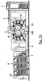
- FIGS 1A and 1B are side views of a sheet-fed offset printing press with an inspection system according to a first embodiment of the invention.
- the printing group of the press which is adapted in this case to perform simultaneous recto-verso offset printing of the sheets, comprises in a conventional manner two blanket cylinders (or printing cylinders) 10, 20 rotating in the direction indicated by the arrows and between which the sheets are fed to receive multicoloured impressions.
- blanket cylinders 10, 20 are three-segment cylinders, i.e. cylinder having a peripheral length approximately three times that of the printing length on the sheets.
- the blanket cylinders 10, 20 receive different inked patterns in their respective colours from plate cylinders 15 and 25 (four on each side) which are distributed around the circumference of the blanket cylinders 10, 20.
- These plate cylinders 15 and 25, which each carry a corresponding printing plate, are themselves inked by corresponding inking devices 13 and 23, respectively, in a manner known in the art.
- the two groups of inking devices 13 and 23 are advantageously placed in two inking carriages that can be moved toward or away from the centrally-located plate cylinders 15, 25 and blanket cylinders 10, 20.
- Sheets are fed from a feeding station 1 located at the right-hand side of the printing group onto a feeding table 2 and then to a succession of transfer cylinders 3 (three cylinders in this example) placed upstream of the blanket cylinders 10, 20. While being transported by the transfer cylinders 3, the sheets may optionally receive a first impression on one side of the sheets using an additional printing group (not illustrated) as described in EP 0 949 069 , one of the transfer cylinders 3 (namely the two-segment cylinder in Figure 1A ) fulfilling the additional function of impression cylinder. In case the sheets are printed by means of the optional additional printing group, these are first dried before being transferred to the blanket cylinders 10, 20 for simultaneous recto-verso printing.
- the sheets are transferred onto the surface of the first blanket cylinder 10 where a leading edge of each sheet is held by appropriate gripper means disposed in cylinder pits between each segment of the blanket cylinder. Each sheet is thus transported by the first blanket cylinder 10 to the printing nip between the blanket cylinders 10 and 20 where simultaneous recto-verso printing occurs. Once printed on both sides, the printed sheets are then transferred as known in the art to a chain gripper system 5 for delivery in a sheet delivery station 6 comprising multiple delivery piles (three in this example).
- the chain gripper system 5 typically comprises a pair of chains holding a plurality of spaced-apart gripper bars (not shown) each provided with a series of grippers for holding a leading edge of the sheets.
- the chain gripper system extends from below the two blanket cylinders 10, 20, through a floor part of the printing press and on top of the three delivery piles of the delivery station 6.
- the gripper bars are driven along this path in a clockwise direction, the path of the chain gripper system 5 going from the printing group to the sheet delivery station 6 running below the return path of the chain gripper system 5.
- Drying means 7 are disposed along the path of the chain gripper system in order to dry both sides of the sheets, drying being performed using infrared lamps and/or UV lamps depending on the type of inks used.
- the drying means 7 are located at a vertical portion of the chain gripper system 5 where the gripper bars are led from the floor part of the printing press to the top of the sheet delivery station 6.
- the pair of chain wheels 51 are disposed in the immediate vicinity of the first blanket cylinder 10 so that printed sheets can be taken away from the surface of the first blanket cylinder 10 and transferred directly to the chain gripper system 5.
- the pair of chain wheels 51 can be disposed at a location where they are not anymore adjacent the first blanket cylinder 10 to accommodate space for one or more transfer cylinders between the blanket cylinder 10 and the chain gripper system 5.
- this inspection device 100 for taking an image of a first side of the printed sheets.
- this inspection device 100 comprises a first line image sensor 110 for performing line-scanning image acquisition of a first side of the printed sheets.
- Line-scanning image acquisition shall be understood as an image acquisition process whereby a surface or object is scanned line after line and the complete image of the surface or object is reconstructed from the plurality of scanned line portions. It is to be understood that line-scanning image acquisition involves a relative displacement of the image sensor with respect of the surface or object to be imaged. In this example, the relative displacement is caused by the rotation of the blanket cylinder 10 transporting the sheet to inspect.
- the first inspection device 100 is disposed in such a way that the first line image sensor 110 visually acquires an image of a printed sheet while the printed sheet is still adhering onto the surface of the first blanket cylinder 10 of the printing press and immediately before the printed sheet is transferred to the chain gripper system 5.
- the first inspection device 100 further comprises a mirror 120 for diverting the optical path of the line image sensor 110 onto the surface of the printing cylinder. This mirror 120 advantageously permits to locate and orient the first inspection device 100 in a very compact manner in the printing press.
- the mirror 120 permits to by-pass the chain wheels 51 and get access to the portion of the circumference of the blanket cylinder 10 between the printing nip and the sheet transfer location where the sheets are transferred to the chain gripper system 5.
- Carrying out inspection at this location has shown to be advantageous as the freshly printed sheet is still adhering to the surface of the blanket cylinder 10.
- the fresh ink has a sticking effect which prevent the sheets from detaching too easily from the surface of the blanket cylinder 10. No smearing problems can accordingly occur as the sheet is still in contact with the printing form.
- the distance between the printing nip and the sheet transfer location being less than the length of the sheet, inspection is carried out at a time where the sheet is still held between the blanket cylinders 10, 20 at the printing nip thereof and/or held by its leading edge by the chain gripper system 5.
- the line image sensor 110 and mirror 120 are disposed below the second blanket cylinder 20 and are oriented in such a manner that a first portion of the optical path of the line image sensor 110 extending between the first line image sensor 110 and the mirror 120 is approximately tangential to the circumference of the second blanket cylinder 20 and that a second portion of the optical path of the line image sensor 110 extending between the mirror 120 and the surface of the first blanket cylinder 10 is approximately perpendicular to the circumference of the blanket cylinder 10.
- a light source 130 is further disposed immediately below the printing nip so as to illuminate the inspected zone on the sheet carried by the blanket cylinder 10.
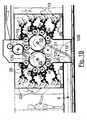
- Figure 2 is a side view of a sheet-fed recto-verso printing press similar to that of Figures 1A and 1B according to a further embodiment of the invention and which shows only the printing group of the printing press with its inspection system.
- the features that are common with those of Figures 1A and 1B are designated by the same reference numerals.
- the only difference with respect to the embodiment of Figures 1A and 1B resides in the provision of additional bearing arrangements for supporting the chain wheels 51 of the chain gripper system 5 as well as additional transfer cylinders (not shown in Figure 2 ).
- four bearings are provided and are designated by reference numerals 301, 302, 303, 304 respectively.
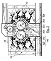
- FIG 3 is a side view of the sheet-fed recto-verso printing press of Figure 2 with the following modifications:
- the machine configuration illustrated in Figure 3 is meant to permit recto-verso inspection of the printed sheets.
- a first side of the sheets is inspected by means of the first inspection device 100 (as in the other embodiments), while the other side of the sheets is inspected by means of the second inspection device 200.
- the second inspection device 200 also comprises a line image sensor 210 for performing line-scanning image acquisition of the other side of the printed sheets. No mirror is required in this example, as the first transfer cylinder 60 enables presenting the other side of the printed sheets directly in front of the line image sensor 210.
- a light source 230 is also disposed in order to appropriately illuminate the inspected zone on the sheet carried by the transfer cylinder 60.
- the transfer cylinder 60 (as well as transfer cylinder 65) is preferably a one-segment cylinder for carrying one sheet at a time and is preferably treated with or comprises an ink-repellent coating for preventing smearing of the printed sheets.
- the transfer cylinders 60, 65 are designed as suction drums with integrated means for aspirating the transported sheet against the surface of the cylinder. Smearing problems are not as such critical in the example of Figure 3 as the printed sheets are directly transferred from the blanket cylinder 10 to the transfer cylinder 60, and from the transfer cylinder 60 to the other transfer cylinder 65.
- first printing cylinder and “second printing cylinder” can designate any of the two printing cylinders.
- second printing cylinder can designate any of the two printing cylinders.
- the invention has been described in connection with a printing press for performing simultaneous recto-verso offset printing, the machine might perform simultaneous printing according to other printing processes.
Landscapes
- Engineering & Computer Science (AREA)
- Quality & Reliability (AREA)
- Inking, Control Or Cleaning Of Printing Machines (AREA)
- Rotary Presses (AREA)
- Supply, Installation And Extraction Of Printed Sheets Or Plates (AREA)
Claims (12)
- Bogenprüfungssystem für eine Schön- und Widerdruck-Bogendruckmaschine, die zwei Druckzylinder (10, 20) zur gleichzeitigen Ausführung von Schön- und Widerdruck der Bogen aufweist, wobei das Bogenprüfungssystem mindestens eine erste Prüfungsvorrichtung (100) zur Aufnahme eines Bildes einer ersten Seite der bedruckten Bogen aufweist,
dadurch gekennzeichnet, dass die erste Prüfungsvorrichtung (100) einen ersten Zeilenbildsensor (110) zur Ausführung einer Zeilenabtastungs-Bilderfassung der ersten Seite der bedruckten Bogen aufweist, und
dass die erste Prüfungsvorrichtung (100) derart angeordnet ist, dass der erste Zeilenbildsensor (110) visuell ein Bild eines bedruckten Bogens erfasst, während der bedruckte Bogen noch auf der Oberfläche eines ersten (10) der zwei Druckzylinder (10, 20) der Druckmaschine anhaftet, und unmittelbar bevor der bedruckte Bogen zu einem Kettengreifersystem (5) der Druckmaschine übertragen wird. - Bogenprüfungssystem nach Anspruch 1, dadurch gekennzeichnet, dass die erste Prüfungsvorrichtung (100) weiterhin einen Spiegel (120) zum Umleiten des Strahlengangs des ersten Zeilenbildsensors (110) auf die Oberfläche des ersten Druckzylinders (10) aufweist.
- Bogenprüfungssystem nach Anspruch 2, dadurch gekennzeichnet, dass der erste Zeilenbildsensor (110) und der Spiegel (120) unter dem zweiten (20) der zwei Druckzylinder (10, 20) angeordnet sind, und dass der erste Zeilenbildsensor (110) und der Spiegel (120) derart ausgerichtet sind, dass ein erster Abschnitt des Strahlengangs des ersten Zeilenbildsensors (110), der sich zwischen dem ersten Zeilenbildsensor (110) und dem Spiegel (120) erstreckt, annähernd tangential zu dem Umfang des zweiten Druckzylinders (20) verläuft, und dass ein zweiter Abschnitt des Strahlengangs des ersten Zeilenbildsensors (110), der sich zwischen dem Spiegel (120) und der Oberfläche des ersten Druckzylinders (10) erstreckt, annähernd senkrecht zu dem Umfang des ersten Druckzylinders (10) verläuft.
- Bogenprüfungssystem nach einem der Ansprüche 1 bis 3, dadurch gekennzeichnet, dass der Strahlengang des ersten Zeilenbildsensors (110) zu einer Position auf dem Umfang des ersten Druckzylinders (10) geleitet wird, der unmittelbar vor einer Bogenübertragungsstelle angeordnet ist, an der die bedruckten Bogen von der Oberfläche des ersten Druckzylinders (10) weggenommen werden.
- Bogenprüfungssystem nach Anspruch 4, dadurch gekennzeichnet, dass die Länge zwischen dem Druckspalt der zwei Druckzylinder (10, 20) und der Bogenübertragungsstelle kleiner als die Länge der bedruckten Bogen ist.
- Bogenprüfungssystem nach einem der vorangehenden Ansprüche, dadurch gekennzeichnet, dass es weiterhin eine zweite Prüfungsvorrichtung (200) zur Aufnahme eines Bildes der anderen Seite der bedruckten Bogen aufweist, wobei die zweite Prüfungsvorrichtung (200) einen zweiten Zeilenbildsensor (210) zur Ausführung einer Zeilenabtastungs-Bilderfassung der anderen Seite der bedruckten Bogen aufweist, wobei das Bogenprüfungssystem mindestens einen zwischen dem ersten Druckzylinder (10) und dem Kettengreifersystem (5) zwischengeschalteten Übertragungszylinder (60; 65) aufweist, um die bedruckten Bogen von der Oberfläche des ersten Druckzylinders (10) wegzunehmen und die andere Seite der bedruckten Bogen der zweiten Prüfungsvorrichtung (200) zur Untersuchung vorzulegen.
- Bogenprüfungssystem nach Anspruch 6, dadurch gekennzeichnet, dass der mindestens eine Übertragungszylinder (60; 65) ein Einzelsegment-Zylinder ist, der jeweils nur einen Bogen trägt.
- Bogenprüfungssystem nach Anspruch 6 oder 7, dadurch gekennzeichnet, dass die Oberfläche des mindestens einen Übertragungszylinders (60; 65) mit einer Druckfarbe abweisenden Beschichtung behandelt ist, um Verschmieren der bedruckten Bogen zu vermeiden.
- Bogenprüfungssystem nach Anspruch 6, 7 oder 8, das zwischen dem ersten Druckzylinder (10) und dem Kettengreifersystem (5) der Druckmaschine positionierte erste und zweite Übertragungszylinder (60, 65) aufweist.
- Bogenprüfungssystem nach einem der Ansprüche 6 bis 9, dadurch gekennzeichnet, dass der mindestens eine Übertragungszylinder (60; 65) als Saugtrommel konstruiert ist.
- Schön- und Widerdruckmaschine zur Ausführung von gleichzeitigem Schön- und Widerdruck auf Bogen, die Folgendes aufweist:ein Druckwerk (10, 13, 15, 20, 23, 25) mit ersten und zweiten berührenden Druckzylindern (10, 20) zum gleichzeitigen Bedrucken beider Seiten von Bogen, die dem Druckspalt zwischen den ersten und zweiten Druckzylindern (10, 20) zugeführt werden;ein Kettengreifersystem (5, 51, 52) zum Transportieren der von dem Druckwerk (10, 13, 15, 20, 23, 25) bedruckten Bogen zu einer Bogenauslegestation (6); undein Prüfungssystem (100; 200) zur Ausführung einer In-Line-Prüfung der bedruckten Bogen,wobei das Prüfungssystem (100; 200) ein System nach einem der vorhergehenden Ansprüche ist.
- Schön- und Widerdruckmaschine nach Anspruch 11, dadurch gekennzeichnet, dass das Kettengreifersystem (5) ein Paar von Kettenrädern (51) aufweist, die in der Nähe des Druckwerkes (10, 13, 15, 20, 23, 25) angeordnet sind, um eine Übertragung der bedruckten Bogen von dem Druckwerk (10, 13, 15, 20, 23, 25) zu dem Kettengreifersystem (5) zu ermöglichen, und dass die Druckmaschine zwei getrennte Lager (302, 304) zum Tragen des Paares von Kettenrädern (51) aufweist, nämlich erste Lager (302) zum Tragen des Paares von Kettenrädern (51) an einer Stelle, an der die Kettenräder (51) an den ersten Druckzylinder (10) angrenzen, so dass die bedruckten Bogen von der Oberfläche des ersten Druckzylinders (10) weggenommen und direkt zu dem Kettengreifersystem (5) übertragen werden, und zweite Lager (304) zum Tragen des Paares von Kettenrädern (51) an einer Stelle, an der die Kettenräder (51) nicht an den ersten Druckzylinder (10) angrenzen, um Raum für zwei Übertragungszylinder (60, 65) bereitzustellen, die in Reihe zwischen den ersten Druckzylinder (10) und das Kettengreifersystem (5) zwischengeschaltet sind.
Priority Applications (1)
| Application Number | Priority Date | Filing Date | Title |
|---|---|---|---|
| EP07713112A EP1996403B1 (de) | 2006-03-14 | 2007-03-08 | Inspektionssystem für eine beidseitig druckende bogendruckmaschine |
Applications Claiming Priority (3)
| Application Number | Priority Date | Filing Date | Title |
|---|---|---|---|
| EP06005169A EP1834779A1 (de) | 2006-03-14 | 2006-03-14 | Inspektionsvorrichtung für eine beidseitige Bogendruckmaschine |
| EP07713112A EP1996403B1 (de) | 2006-03-14 | 2007-03-08 | Inspektionssystem für eine beidseitig druckende bogendruckmaschine |
| PCT/IB2007/000564 WO2007105061A1 (en) | 2006-03-14 | 2007-03-08 | Inspection system for a sheet-fed recto-verso printing press |
Publications (2)
| Publication Number | Publication Date |
|---|---|
| EP1996403A1 EP1996403A1 (de) | 2008-12-03 |
| EP1996403B1 true EP1996403B1 (de) | 2011-05-11 |
Family
ID=36829841
Family Applications (3)
| Application Number | Title | Priority Date | Filing Date |
|---|---|---|---|
| EP06005169A Withdrawn EP1834779A1 (de) | 2006-03-14 | 2006-03-14 | Inspektionsvorrichtung für eine beidseitige Bogendruckmaschine |
| EP07713112A Active EP1996403B1 (de) | 2006-03-14 | 2007-03-08 | Inspektionssystem für eine beidseitig druckende bogendruckmaschine |
| EP07733934A Active EP1996404B1 (de) | 2006-03-14 | 2007-03-08 | Inspektionssystem für eine beidseitige bogendruckmaschine |
Family Applications Before (1)
| Application Number | Title | Priority Date | Filing Date |
|---|---|---|---|
| EP06005169A Withdrawn EP1834779A1 (de) | 2006-03-14 | 2006-03-14 | Inspektionsvorrichtung für eine beidseitige Bogendruckmaschine |
Family Applications After (1)
| Application Number | Title | Priority Date | Filing Date |
|---|---|---|---|
| EP07733934A Active EP1996404B1 (de) | 2006-03-14 | 2007-03-08 | Inspektionssystem für eine beidseitige bogendruckmaschine |
Country Status (8)
| Country | Link |
|---|---|
| US (2) | US8065957B2 (de) |
| EP (3) | EP1834779A1 (de) |
| JP (2) | JP5064418B2 (de) |
| CN (2) | CN101400519B (de) |
| AT (2) | ATE508873T1 (de) |
| ES (2) | ES2364503T3 (de) |
| RU (2) | RU2413618C2 (de) |
| WO (2) | WO2007105059A1 (de) |
Cited By (3)
| Publication number | Priority date | Publication date | Assignee | Title |
|---|---|---|---|---|
| DE102012218423A1 (de) * | 2012-10-10 | 2014-04-10 | Koenig & Bauer Aktiengesellschaft | Farbwerk eines Druckwerks, Druckwerk sowie Verfahren zum Betreiben eines Farbwerks |
| DE102012218417A1 (de) | 2012-10-10 | 2014-04-10 | Koenig & Bauer Aktiengesellschaft | Farbwerk eines Druckwerks, Druckwerk sowie Verfahren zum Betreiben eines Druckwerks |
| WO2014056711A1 (de) | 2012-10-10 | 2014-04-17 | Koenig & Bauer Aktiengesellschaft | Farbwerke eines druckwerks, druckwerk sowie verfahren zum betreiben eines druckwerks |
Families Citing this family (26)
| Publication number | Priority date | Publication date | Assignee | Title |
|---|---|---|---|---|
| EP1995062A1 (de) * | 2007-05-25 | 2008-11-26 | Kba-Giori S.A. | Tiefdruckpressensysteme zum beidseitigem Bedrucken von Bogen, insbesondere zur Herstellung von Banknoten und ähnlichen Wertdokumenten |
| DE102007046163B4 (de) * | 2007-09-27 | 2018-12-20 | Manroland Web Systems Gmbh | Druckeinheit für eine Rotationsdruckmaschine |
| EP2045783A1 (de) | 2007-10-02 | 2009-04-08 | Kba-Giori S.A. | Verfahren und System für die kontrollierte Produktion von Sicherheitsdokumenten, vor allem Banknoten |
| WO2010039135A1 (en) | 2008-10-01 | 2010-04-08 | Hewlett-Packard Development Company, L.P. | Camera web support |
| EP2399745A1 (de) * | 2010-06-25 | 2011-12-28 | KBA-NotaSys SA | Inspektionssystem für Inline-Inspektion von auf einer Intaglio-Druckpresse hergestelltem Druckmaterial |
| JP2012061602A (ja) * | 2010-09-14 | 2012-03-29 | Komori Corp | 凹版印刷機 |
| EP2439071A1 (de) | 2010-10-11 | 2012-04-11 | KBA-NotaSys SA | Farbsteuerungsmuster zur optischen Messung von mit einer mehrfarbigen Druckpresse auf einem blatt- oder bahnförmigen Substrat gedruckten Farben und Verwendungen dafür |
| JP5798742B2 (ja) * | 2010-12-24 | 2015-10-21 | 株式会社小森コーポレーション | 番号印刷機 |
| EP2505356A1 (de) | 2011-03-30 | 2012-10-03 | KBA-NotaSys SA | Vorrichtung zur Offline-Prüfung und Farbmessung von Druckbögen |
| CA2839394C (en) | 2011-06-30 | 2016-01-05 | Koenig & Bauer Aktiengesellschaft | Method of mounting and registering a printing plate on a plate cylinder of a multicolour offset printing press |
| JP2013107388A (ja) * | 2011-10-26 | 2013-06-06 | Komori Corp | 凹版印刷機 |
| EP2637396A1 (de) | 2012-03-07 | 2013-09-11 | KBA-NotaSys SA | Verfahren zur Überprüfung der Herstellbarkeit eines zusammengestelltes Sicherheitsdesigns eines Sicherheitsdokumentes auf einer Druckstrasse, und digitale Computerumgebung zur Umsetzung davon |
| EP2650131A1 (de) | 2012-04-10 | 2013-10-16 | KBA-NotaSys SA | Druckpresse mit mobilem Tintenschlitten |
| JP6075598B2 (ja) * | 2012-07-03 | 2017-02-08 | 株式会社小森コーポレーション | 両面印刷機の検査装置 |
| CN103522733B (zh) | 2012-07-03 | 2017-04-12 | 小森公司 | 双面印刷机 |
| JP2014100819A (ja) * | 2012-11-19 | 2014-06-05 | Komori Corp | 印刷機 |
| EP2774759A1 (de) | 2013-03-07 | 2014-09-10 | KBA-NotaSys SA | Formzylinder einer Rotationsdruckpresse mit Bogenzuführung zur Herstellung von Banknoten und ähnlichen Wertdokumenten |
| CN103434268B (zh) * | 2013-08-21 | 2016-09-14 | 北京华夏视科图像技术有限公司 | 用于印刷设备的检测系统 |
| EP2998117A1 (de) | 2014-09-19 | 2016-03-23 | KBA-NotaSys SA | Farbwerk einer Druckermaschine, Druckmaschine und Verfahren zur Herstellung einer Heberwalze |
| EP3017946A1 (de) * | 2014-11-07 | 2016-05-11 | KBA-NotaSys SA | Druckpresse zum gleichzeitigen Schöndruck/Widerdruck |
| EP3246160A1 (de) | 2016-05-19 | 2017-11-22 | KBA-NotaSys SA | Messung und korrektur des print-to-print-registers eines mehrfarbendrucks auf druckmaterial |
| EP3366474B1 (de) | 2017-02-22 | 2020-06-24 | KBA-NotaSys SA | Druckpresse mit inline-giessvorrichtung zur replizierung und bildung einer mikrooptischen struktur |
| HUE044887T2 (hu) | 2017-03-14 | 2019-11-28 | Kba Notasys Sa | Ívadagolós nyomógép ívek elülsõ- és hátoldalának egyidejû nyomtatására, különösen biztonsági dokumentumok elõállításához |
| EP3489029B1 (de) | 2017-11-27 | 2019-12-25 | KBA-Notasys SA | Gedrucktes sicherheitselement mit einem regenbogenmerkmal und verfahren zur herstellung davon |
| CN109228614B (zh) * | 2018-09-12 | 2020-10-27 | 西安印钞有限公司 | 双面一次性涂布设备 |
| CN110001193B (zh) * | 2019-04-24 | 2021-04-27 | 浙江宏晟包装科技有限公司 | 一种图像印刷管理装置 |
Family Cites Families (31)
| Publication number | Priority date | Publication date | Assignee | Title |
|---|---|---|---|---|
| CH502897A (de) | 1970-05-26 | 1971-02-15 | De La Rue Giori Sa | Mehrfarben-Offset-Rotationsdruckmaschine |
| US3835777A (en) * | 1973-01-16 | 1974-09-17 | Harris Intertype Corp | Ink density control system |
| US4210078A (en) * | 1974-06-24 | 1980-07-01 | M.A.N.-Roland Druckmaschinen Aktiengesellschaft | Apparatus for use on printing presses to insure optimum color density and to assist in making corrective adjustment |
| JPS57205153A (en) * | 1981-06-13 | 1982-12-16 | Komori Printing Mach Co Ltd | Inspecting rotary press |
| JPS6225047A (ja) * | 1985-07-25 | 1987-02-03 | Toppan Printing Co Ltd | 印刷物検査装置 |
| JP2617102B2 (ja) * | 1986-09-08 | 1997-06-04 | 株式会社 小森コーポレーション | 枚葉輪転印刷機 |
| US4836104A (en) * | 1987-06-05 | 1989-06-06 | Duarte Products, Inc. | Sheet transfer mechanism for a freshly printed sheet |
| ATE61286T1 (de) | 1987-11-27 | 1991-03-15 | Komori Printing Mach | Bogenrotationsdruckmaschine. |
| US5205217A (en) | 1990-12-31 | 1993-04-27 | Howard W. DeMoore | Vacuum transfer apparatus for rotary sheet-fed printing presses |
| DE9116439U1 (de) | 1991-08-14 | 1992-11-12 | Koenig & Bauer Ag, 8700 Wuerzburg, De | |
| DE4217942A1 (de) | 1992-05-30 | 1993-12-02 | Koenig & Bauer Ag | Druck-Qualitätskontrolleinrichtung für eine Schön- und Widerdruck-Rotationsdruckmaschine |
| SE501564C2 (sv) | 1993-06-18 | 1995-03-13 | Btg Kaelle Inventing Ab | Bestrykningsanordning för en eller tvåsidig bestrykning av en löpande bana |
| DE4321177A1 (de) * | 1993-06-25 | 1995-01-05 | Heidelberger Druckmasch Ag | Vorrichtung zur parallelen Bildinspektion und Farbregelung an einem Druckprodukt |
| MY119247A (en) * | 1994-10-31 | 2005-04-30 | Tdk Corp | Manufacturing method and manufacturing apparatus for ceramic electronic components |
| DE19624196C2 (de) * | 1996-06-18 | 1999-09-23 | Koenig & Bauer Ag | Vorrichtung und Verfahren Bogenführung bei einer qualitativen Beurteilung von bearbeiteten Bogen |
| EP1054771B1 (de) * | 1998-02-13 | 2002-06-26 | Koenig & Bauer Aktiengesellschaft | Verfahren und vorrichtungen zum transport von bogen |
| CA2266090C (en) | 1998-04-08 | 2007-07-03 | De La Rue Giori S.A. | Rotary printing machine for security papers |
| JP2001096713A (ja) | 1999-09-30 | 2001-04-10 | Komori Corp | 印刷機 |
| JP4421066B2 (ja) | 2000-04-07 | 2010-02-24 | 株式会社小森コーポレーション | 両面印刷機の品質検査装置 |
| KR20030007585A (ko) * | 2000-05-08 | 2003-01-23 | 케이비에이-지오리 에스.에이. | 인쇄지 형태의 재료를 운반하기 위한 장치 |
| UA73186C2 (en) * | 2000-05-08 | 2005-06-15 | Kba Giori Sa | Installation and method for treatment of paper sheets with two-sided printing |
| JP4950374B2 (ja) | 2000-06-23 | 2012-06-13 | 株式会社小森コーポレーション | シート状物識別方法および識別装置 |
| JP4616451B2 (ja) * | 2000-09-22 | 2011-01-19 | 株式会社小森コーポレーション | 印刷品質検査装置 |
| DE10128833B4 (de) * | 2001-06-15 | 2006-11-02 | Koenig & Bauer Ag | Qualitätskontrollvorrichtung |
| JP2003251789A (ja) * | 2001-12-27 | 2003-09-09 | Komori Corp | 印刷機の印刷品質検査装置 |
| ATE398528T1 (de) * | 2003-03-13 | 2008-07-15 | Bieffebi Spa | Andruckpresse zur befestigung von flexodruckplatten |
| JP2005007858A (ja) * | 2003-06-18 | 2005-01-13 | Heidelberger Druckmas Ag | 被印刷体枚葉紙を処理する機械を運転する方法 |
| DE10332212A1 (de) * | 2003-07-16 | 2005-02-24 | Koenig & Bauer Ag | Vorrichtungen zur Qualitätsprüfung von Prüfkörpern und ein Verfahren zum Prüfen der Qualität von Bogen |
| JP4437392B2 (ja) * | 2003-09-22 | 2010-03-24 | 大日本スクリーン製造株式会社 | インキ供給方法およびインキ供給装置 |
| DE102004021597B4 (de) * | 2004-05-03 | 2017-04-13 | Heidelberger Druckmaschinen Ag | Registermarke |
| ITMI20041054A1 (it) * | 2004-05-26 | 2004-08-26 | Riparazioni Macchine Grafi Ce | Apparecchiatura di verifica per fogli valore e relativo metodo di controllo di una macchina da stampa |
-
2006
- 2006-03-14 EP EP06005169A patent/EP1834779A1/de not_active Withdrawn
-
2007
- 2007-03-08 WO PCT/IB2007/000562 patent/WO2007105059A1/en active Application Filing
- 2007-03-08 RU RU2008140521/12A patent/RU2413618C2/ru not_active IP Right Cessation
- 2007-03-08 CN CN2007800087944A patent/CN101400519B/zh not_active Expired - Fee Related
- 2007-03-08 EP EP07713112A patent/EP1996403B1/de active Active
- 2007-03-08 AT AT07713112T patent/ATE508873T1/de active
- 2007-03-08 JP JP2008558928A patent/JP5064418B2/ja active Active
- 2007-03-08 WO PCT/IB2007/000564 patent/WO2007105061A1/en active Application Filing
- 2007-03-08 ES ES07713112T patent/ES2364503T3/es active Active
- 2007-03-08 US US12/281,248 patent/US8065957B2/en active Active
- 2007-03-08 US US12/281,244 patent/US8528477B2/en active Active
- 2007-03-08 ES ES07733934T patent/ES2364436T3/es active Active
- 2007-03-08 JP JP2008558930A patent/JP5064419B2/ja active Active
- 2007-03-08 RU RU2008140520/12A patent/RU2413617C2/ru not_active IP Right Cessation
- 2007-03-08 AT AT07733934T patent/ATE508874T1/de active
- 2007-03-08 EP EP07733934A patent/EP1996404B1/de active Active
- 2007-03-08 CN CN2007800088218A patent/CN101400520B/zh not_active Expired - Fee Related
Cited By (4)
| Publication number | Priority date | Publication date | Assignee | Title |
|---|---|---|---|---|
| DE102012218423A1 (de) * | 2012-10-10 | 2014-04-10 | Koenig & Bauer Aktiengesellschaft | Farbwerk eines Druckwerks, Druckwerk sowie Verfahren zum Betreiben eines Farbwerks |
| DE102012218417A1 (de) | 2012-10-10 | 2014-04-10 | Koenig & Bauer Aktiengesellschaft | Farbwerk eines Druckwerks, Druckwerk sowie Verfahren zum Betreiben eines Druckwerks |
| WO2014056711A1 (de) | 2012-10-10 | 2014-04-17 | Koenig & Bauer Aktiengesellschaft | Farbwerke eines druckwerks, druckwerk sowie verfahren zum betreiben eines druckwerks |
| DE102012218423B4 (de) | 2012-10-10 | 2022-02-24 | Koenig & Bauer Ag | Farbwerk eines Druckwerks, Druckwerk sowie Verfahren zum Betreiben eines Farbwerks |
Also Published As
| Publication number | Publication date |
|---|---|
| US20090025594A1 (en) | 2009-01-29 |
| WO2007105059A1 (en) | 2007-09-20 |
| US20090007807A1 (en) | 2009-01-08 |
| RU2008140520A (ru) | 2010-04-20 |
| RU2413617C2 (ru) | 2011-03-10 |
| JP2009530131A (ja) | 2009-08-27 |
| CN101400519B (zh) | 2011-11-16 |
| EP1996403A1 (de) | 2008-12-03 |
| RU2413618C2 (ru) | 2011-03-10 |
| RU2008140521A (ru) | 2010-04-20 |
| JP5064419B2 (ja) | 2012-10-31 |
| CN101400520A (zh) | 2009-04-01 |
| EP1996404A1 (de) | 2008-12-03 |
| CN101400520B (zh) | 2010-09-08 |
| CN101400519A (zh) | 2009-04-01 |
| JP5064418B2 (ja) | 2012-10-31 |
| EP1996404B1 (de) | 2011-05-11 |
| JP2009530130A (ja) | 2009-08-27 |
| US8528477B2 (en) | 2013-09-10 |
| WO2007105061A1 (en) | 2007-09-20 |
| ATE508873T1 (de) | 2011-05-15 |
| ES2364503T3 (es) | 2011-09-05 |
| ES2364436T3 (es) | 2011-09-02 |
| US8065957B2 (en) | 2011-11-29 |
| EP1834779A1 (de) | 2007-09-19 |
| ATE508874T1 (de) | 2011-05-15 |
Similar Documents
| Publication | Publication Date | Title |
|---|---|---|
| EP1996403B1 (de) | Inspektionssystem für eine beidseitig druckende bogendruckmaschine | |
| CN110402196B (zh) | 同时印刷片材的正反面尤其是用于生产安全文件的单张片材印刷机 | |
| EP3130467B1 (de) | Druckpresse zur nummerierung und lackierung von sicherheitsdokumenten, insbesondere von banknoten | |
| US11772374B2 (en) | Printing press with in-line casting device for the replication and formation of a micro-optical structure | |
| JP2013099952A (ja) | 紙幣および同様の有価証券を製造するために枚葉紙の表面−裏面に凹版印刷する凹版印刷機システム | |
| US20010027730A1 (en) | Quality inspection apparatus for double-sided printing machine | |
| EP3215366B1 (de) | Druckpresse zum gleichzeitigen schöndruck/widerdruck | |
| US11312125B2 (en) | Sheet-fed printing machine having a simultaneous printing unit for security printing | |
| US20210086498A1 (en) | Sheet-fed printing machine for different printing methods | |
| CA2052714C (en) | Sheet-fed offset rotary printing machine | |
| US11390064B2 (en) | Printing press and method for producing security products or security intermediate products | |
| US6546862B1 (en) | Method and device for producing a multicolor print | |
| EP4037905B1 (de) | Druckmaschine mit einer vorrichtung zum erfassen der anwesenheit einer auftragsform und verfahren zum zuführen einer auftragsform |
Legal Events
| Date | Code | Title | Description |
|---|---|---|---|
| PUAI | Public reference made under article 153(3) epc to a published international application that has entered the european phase |
Free format text: ORIGINAL CODE: 0009012 |
|
| 17P | Request for examination filed |
Effective date: 20081002 |
|
| AK | Designated contracting states |
Kind code of ref document: A1 Designated state(s): AT BE BG CH CY CZ DE DK EE ES FI FR GB GR HU IE IS IT LI LT LU LV MC MT NL PL PT RO SE SI SK TR |
|
| 17Q | First examination report despatched |
Effective date: 20090323 |
|
| RAP1 | Party data changed (applicant data changed or rights of an application transferred) |
Owner name: KBA-GIORI S.A. |
|
| GRAP | Despatch of communication of intention to grant a patent |
Free format text: ORIGINAL CODE: EPIDOSNIGR1 |
|
| RAP1 | Party data changed (applicant data changed or rights of an application transferred) |
Owner name: KBA-NOTASYS SA |
|
| GRAS | Grant fee paid |
Free format text: ORIGINAL CODE: EPIDOSNIGR3 |
|
| GRAA | (expected) grant |
Free format text: ORIGINAL CODE: 0009210 |
|
| AK | Designated contracting states |
Kind code of ref document: B1 Designated state(s): AT BE BG CH CY CZ DE DK EE ES FI FR GB GR HU IE IS IT LI LT LU LV MC MT NL PL PT RO SE SI SK TR |
|
| REG | Reference to a national code |
Ref country code: GB Ref legal event code: FG4D |
|
| REG | Reference to a national code |
Ref country code: CH Ref legal event code: EP |
|
| REG | Reference to a national code |
Ref country code: IE Ref legal event code: FG4D |
|
| REG | Reference to a national code |
Ref country code: DE Ref legal event code: R096 Ref document number: 602007014487 Country of ref document: DE Effective date: 20110622 |
|
| REG | Reference to a national code |
Ref country code: SE Ref legal event code: TRGR |
|
| REG | Reference to a national code |
Ref country code: NL Ref legal event code: T3 |
|
| REG | Reference to a national code |
Ref country code: ES Ref legal event code: FG2A Ref document number: 2364503 Country of ref document: ES Kind code of ref document: T3 Effective date: 20110905 |
|
| PG25 | Lapsed in a contracting state [announced via postgrant information from national office to epo] |
Ref country code: PT Free format text: LAPSE BECAUSE OF FAILURE TO SUBMIT A TRANSLATION OF THE DESCRIPTION OR TO PAY THE FEE WITHIN THE PRESCRIBED TIME-LIMIT Effective date: 20110912 Ref country code: LT Free format text: LAPSE BECAUSE OF FAILURE TO SUBMIT A TRANSLATION OF THE DESCRIPTION OR TO PAY THE FEE WITHIN THE PRESCRIBED TIME-LIMIT Effective date: 20110511 |
|
| PG25 | Lapsed in a contracting state [announced via postgrant information from national office to epo] |
Ref country code: FI Free format text: LAPSE BECAUSE OF FAILURE TO SUBMIT A TRANSLATION OF THE DESCRIPTION OR TO PAY THE FEE WITHIN THE PRESCRIBED TIME-LIMIT Effective date: 20110511 Ref country code: BE Free format text: LAPSE BECAUSE OF FAILURE TO SUBMIT A TRANSLATION OF THE DESCRIPTION OR TO PAY THE FEE WITHIN THE PRESCRIBED TIME-LIMIT Effective date: 20110511 Ref country code: CY Free format text: LAPSE BECAUSE OF FAILURE TO SUBMIT A TRANSLATION OF THE DESCRIPTION OR TO PAY THE FEE WITHIN THE PRESCRIBED TIME-LIMIT Effective date: 20110511 Ref country code: SI Free format text: LAPSE BECAUSE OF FAILURE TO SUBMIT A TRANSLATION OF THE DESCRIPTION OR TO PAY THE FEE WITHIN THE PRESCRIBED TIME-LIMIT Effective date: 20110511 Ref country code: GR Free format text: LAPSE BECAUSE OF FAILURE TO SUBMIT A TRANSLATION OF THE DESCRIPTION OR TO PAY THE FEE WITHIN THE PRESCRIBED TIME-LIMIT Effective date: 20110812 Ref country code: LV Free format text: LAPSE BECAUSE OF FAILURE TO SUBMIT A TRANSLATION OF THE DESCRIPTION OR TO PAY THE FEE WITHIN THE PRESCRIBED TIME-LIMIT Effective date: 20110511 Ref country code: IS Free format text: LAPSE BECAUSE OF FAILURE TO SUBMIT A TRANSLATION OF THE DESCRIPTION OR TO PAY THE FEE WITHIN THE PRESCRIBED TIME-LIMIT Effective date: 20110911 |
|
| PG25 | Lapsed in a contracting state [announced via postgrant information from national office to epo] |
Ref country code: EE Free format text: LAPSE BECAUSE OF FAILURE TO SUBMIT A TRANSLATION OF THE DESCRIPTION OR TO PAY THE FEE WITHIN THE PRESCRIBED TIME-LIMIT Effective date: 20110511 Ref country code: CZ Free format text: LAPSE BECAUSE OF FAILURE TO SUBMIT A TRANSLATION OF THE DESCRIPTION OR TO PAY THE FEE WITHIN THE PRESCRIBED TIME-LIMIT Effective date: 20110511 |
|
| PG25 | Lapsed in a contracting state [announced via postgrant information from national office to epo] |
Ref country code: RO Free format text: LAPSE BECAUSE OF FAILURE TO SUBMIT A TRANSLATION OF THE DESCRIPTION OR TO PAY THE FEE WITHIN THE PRESCRIBED TIME-LIMIT Effective date: 20110511 Ref country code: DK Free format text: LAPSE BECAUSE OF FAILURE TO SUBMIT A TRANSLATION OF THE DESCRIPTION OR TO PAY THE FEE WITHIN THE PRESCRIBED TIME-LIMIT Effective date: 20110511 Ref country code: SK Free format text: LAPSE BECAUSE OF FAILURE TO SUBMIT A TRANSLATION OF THE DESCRIPTION OR TO PAY THE FEE WITHIN THE PRESCRIBED TIME-LIMIT Effective date: 20110511 Ref country code: PL Free format text: LAPSE BECAUSE OF FAILURE TO SUBMIT A TRANSLATION OF THE DESCRIPTION OR TO PAY THE FEE WITHIN THE PRESCRIBED TIME-LIMIT Effective date: 20110511 |
|
| PLBE | No opposition filed within time limit |
Free format text: ORIGINAL CODE: 0009261 |
|
| STAA | Information on the status of an ep patent application or granted ep patent |
Free format text: STATUS: NO OPPOSITION FILED WITHIN TIME LIMIT |
|
| 26N | No opposition filed |
Effective date: 20120214 |
|
| REG | Reference to a national code |
Ref country code: DE Ref legal event code: R097 Ref document number: 602007014487 Country of ref document: DE Effective date: 20120214 |
|
| PG25 | Lapsed in a contracting state [announced via postgrant information from national office to epo] |
Ref country code: MC Free format text: LAPSE BECAUSE OF NON-PAYMENT OF DUE FEES Effective date: 20120331 |
|
| REG | Reference to a national code |
Ref country code: IE Ref legal event code: MM4A |
|
| PG25 | Lapsed in a contracting state [announced via postgrant information from national office to epo] |
Ref country code: IE Free format text: LAPSE BECAUSE OF NON-PAYMENT OF DUE FEES Effective date: 20120308 |
|
| PG25 | Lapsed in a contracting state [announced via postgrant information from national office to epo] |
Ref country code: BG Free format text: LAPSE BECAUSE OF FAILURE TO SUBMIT A TRANSLATION OF THE DESCRIPTION OR TO PAY THE FEE WITHIN THE PRESCRIBED TIME-LIMIT Effective date: 20110811 |
|
| PG25 | Lapsed in a contracting state [announced via postgrant information from national office to epo] |
Ref country code: MT Free format text: LAPSE BECAUSE OF FAILURE TO SUBMIT A TRANSLATION OF THE DESCRIPTION OR TO PAY THE FEE WITHIN THE PRESCRIBED TIME-LIMIT Effective date: 20110511 |
|
| PG25 | Lapsed in a contracting state [announced via postgrant information from national office to epo] |
Ref country code: TR Free format text: LAPSE BECAUSE OF FAILURE TO SUBMIT A TRANSLATION OF THE DESCRIPTION OR TO PAY THE FEE WITHIN THE PRESCRIBED TIME-LIMIT Effective date: 20110511 |
|
| PG25 | Lapsed in a contracting state [announced via postgrant information from national office to epo] |
Ref country code: LU Free format text: LAPSE BECAUSE OF NON-PAYMENT OF DUE FEES Effective date: 20120308 |
|
| PG25 | Lapsed in a contracting state [announced via postgrant information from national office to epo] |
Ref country code: HU Free format text: LAPSE BECAUSE OF FAILURE TO SUBMIT A TRANSLATION OF THE DESCRIPTION OR TO PAY THE FEE WITHIN THE PRESCRIBED TIME-LIMIT Effective date: 20070308 |
|
| REG | Reference to a national code |
Ref country code: FR Ref legal event code: PLFP Year of fee payment: 10 |
|
| REG | Reference to a national code |
Ref country code: FR Ref legal event code: PLFP Year of fee payment: 11 |
|
| PGFP | Annual fee paid to national office [announced via postgrant information from national office to epo] |
Ref country code: NL Payment date: 20170321 Year of fee payment: 11 |
|
| REG | Reference to a national code |
Ref country code: FR Ref legal event code: PLFP Year of fee payment: 12 |
|
| REG | Reference to a national code |
Ref country code: NL Ref legal event code: MM Effective date: 20180401 |
|
| PG25 | Lapsed in a contracting state [announced via postgrant information from national office to epo] |
Ref country code: NL Free format text: LAPSE BECAUSE OF NON-PAYMENT OF DUE FEES Effective date: 20180401 |
|
| PGFP | Annual fee paid to national office [announced via postgrant information from national office to epo] |
Ref country code: IT Payment date: 20200331 Year of fee payment: 14 Ref country code: GB Payment date: 20200324 Year of fee payment: 14 Ref country code: SE Payment date: 20200320 Year of fee payment: 14 Ref country code: AT Payment date: 20200323 Year of fee payment: 14 |
|
| PGFP | Annual fee paid to national office [announced via postgrant information from national office to epo] |
Ref country code: ES Payment date: 20200402 Year of fee payment: 14 Ref country code: FR Payment date: 20200401 Year of fee payment: 14 |
|
| REG | Reference to a national code |
Ref country code: AT Ref legal event code: MM01 Ref document number: 508873 Country of ref document: AT Kind code of ref document: T Effective date: 20210308 |
|
| GBPC | Gb: european patent ceased through non-payment of renewal fee |
Effective date: 20210308 |
|
| PG25 | Lapsed in a contracting state [announced via postgrant information from national office to epo] |
Ref country code: SE Free format text: LAPSE BECAUSE OF NON-PAYMENT OF DUE FEES Effective date: 20210309 Ref country code: GB Free format text: LAPSE BECAUSE OF NON-PAYMENT OF DUE FEES Effective date: 20210308 Ref country code: FR Free format text: LAPSE BECAUSE OF NON-PAYMENT OF DUE FEES Effective date: 20210331 Ref country code: AT Free format text: LAPSE BECAUSE OF NON-PAYMENT OF DUE FEES Effective date: 20210308 |
|
| PG25 | Lapsed in a contracting state [announced via postgrant information from national office to epo] |
Ref country code: IT Free format text: LAPSE BECAUSE OF NON-PAYMENT OF DUE FEES Effective date: 20210308 |
|
| REG | Reference to a national code |
Ref country code: ES Ref legal event code: FD2A Effective date: 20220523 |
|
| PG25 | Lapsed in a contracting state [announced via postgrant information from national office to epo] |
Ref country code: ES Free format text: LAPSE BECAUSE OF NON-PAYMENT OF DUE FEES Effective date: 20210309 |
|
| PGFP | Annual fee paid to national office [announced via postgrant information from national office to epo] |
Ref country code: CH Payment date: 20230402 Year of fee payment: 17 |
|
| PGFP | Annual fee paid to national office [announced via postgrant information from national office to epo] |
Ref country code: DE Payment date: 20240301 Year of fee payment: 18 |