EP1990481A2 - Mantelstein für Schornsteinsysteme - Google Patents
Mantelstein für Schornsteinsysteme Download PDFInfo
- Publication number
- EP1990481A2 EP1990481A2 EP08007922A EP08007922A EP1990481A2 EP 1990481 A2 EP1990481 A2 EP 1990481A2 EP 08007922 A EP08007922 A EP 08007922A EP 08007922 A EP08007922 A EP 08007922A EP 1990481 A2 EP1990481 A2 EP 1990481A2
- Authority
- EP
- European Patent Office
- Prior art keywords
- mantle
- jacket
- chimney
- stone
- separating ring
- Prior art date
- Legal status (The legal status is an assumption and is not a legal conclusion. Google has not performed a legal analysis and makes no representation as to the accuracy of the status listed.)
- Granted
Links
Images


Classifications
-
- E—FIXED CONSTRUCTIONS
- E04—BUILDING
- E04F—FINISHING WORK ON BUILDINGS, e.g. STAIRS, FLOORS
- E04F17/00—Vertical ducts; Channels, e.g. for drainage
- E04F17/02—Vertical ducts; Channels, e.g. for drainage for carrying away waste gases, e.g. flue gases; Building elements specially designed therefor, e.g. shaped bricks or sets thereof
- E04F17/023—Vertical ducts; Channels, e.g. for drainage for carrying away waste gases, e.g. flue gases; Building elements specially designed therefor, e.g. shaped bricks or sets thereof made of masonry, concrete or other stone-like material; Insulating measures and joints therefor
-
- F—MECHANICAL ENGINEERING; LIGHTING; HEATING; WEAPONS; BLASTING
- F23—COMBUSTION APPARATUS; COMBUSTION PROCESSES
- F23J—REMOVAL OR TREATMENT OF COMBUSTION PRODUCTS OR COMBUSTION RESIDUES; FLUES
- F23J13/00—Fittings for chimneys or flues
- F23J13/02—Linings; Jackets; Casings
-
- F—MECHANICAL ENGINEERING; LIGHTING; HEATING; WEAPONS; BLASTING
- F23—COMBUSTION APPARATUS; COMBUSTION PROCESSES
- F23J—REMOVAL OR TREATMENT OF COMBUSTION PRODUCTS OR COMBUSTION RESIDUES; FLUES
- F23J2213/00—Chimneys or flues
- F23J2213/30—Specific materials
- F23J2213/305—Specific materials glass
-
- F—MECHANICAL ENGINEERING; LIGHTING; HEATING; WEAPONS; BLASTING
- F23—COMBUSTION APPARATUS; COMBUSTION PROCESSES
- F23J—REMOVAL OR TREATMENT OF COMBUSTION PRODUCTS OR COMBUSTION RESIDUES; FLUES
- F23J2213/00—Chimneys or flues
- F23J2213/40—Heat insulation fittings
Definitions
- the invention relates to a casing brick for chimney systems and its use of the already known under the trademark "ABSOLUT" the Schiedel AG genus.
- mantle stones are arranged one above the other to form the chimney system. They have a particular cylindrical opening, which serves to receive an inner tube through which, for example, the combustion air is passed through the chimney into the open air.
- the inner wall is made around the opening of heat-insulating material, such as foam concrete.
- This inner wall is in particular radially outwardly surrounded by a jacket made of a load-bearing material, such as lightweight concrete. Its load bearing capacity is determined by the height and weight of the other mantle stones or other accessories used for forming the chimney.
- the invention has the object to improve bricks of the type mentioned in that with the help of the same chimneys for low-energy houses or so-called "passive houses” are easy to assemble.
- the chimney extending from top to bottom through a building does not form a "cold bridge” or "cold vein".
- "cold bridges” occur in known double-walled cladding with a thermally insulating inner wall and a durable jacket around the inner wall around. Cooling air flowing over the building roof or the building cover then leads to a cooling in the rooms below the building cover around the mantle stones placed one above the other there.
- the invention provides a kind of "cold barrier", in particular transversely to the longitudinal direction of the chimney, specifically in the area of the building cover.
- the heat insulating according to the invention and the viable material of the jacket of the jacket stone separating separating ring is just like the viable material above and below the separator ring integral part of the jacket stone. It is therefore not necessary to take any additional measures to set up the "cold barrier" when constructing the chimney system. It is only necessary, in particular at the critical point of the opening through the roof covering, to use a casing stone according to the invention instead of the known casing stones in the row of casing stones to be arranged one above the other.
- foamed glass material in particular foamglass
- foamglass is particularly suitable for the separating ring.
- its good heat insulating properties of the separating ring then has a sufficient load capacity.
- the length of the separating ring in the longitudinal direction of the chimney should be between 5 and 15 cm, while the thickness of the Separating ring (transverse to the longitudinal direction of the chimney) should be about the same thickness as the inner wall of particular heat-insulating material.
- the mantle according to the invention in the passage area of the chimney through the building cover is installed so that the upper part is surrounded by a cuff-shaped, heat-insulating outer shell to the separating ring, as an additional "cold barrier" in the area and above the building cover is effective.
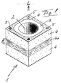
- the mantle 1 has a longitudinally extending L and here cylindrical aperture 2.
- an inner tube 3 is formed as an integral part of the casing stone 1; this inner tube 3 is made of foam concrete, in which the thermal insulation effect is favored by air bubbles in the concrete.
- the jacket 4 is also formed as an integral part of the jacket stone 1. This is made of durable material, such as lightweight concrete. Longitudinally through the casing stone 1 further openings 5 can be arranged in the longitudinal direction L in order to produce additional connecting channels in the longitudinal direction of the chimney system.
- Fig. 4 is within the building 6 in the vertical longitudinal direction L a chimney system 7 over several floors to the building cover 8 also built.
- the inner tube not shown here, is surrounded by individual casing blocks 1 to the outside.
- an inventive coat stone with the not shown here separating ring. This mantle at the point X is within the chimney head 9 and a further below the same surrounded by a cuff-shaped outer shell 10 of heat-insulating material, as even better with reference to Fig. 5 is illustrated.
Landscapes
- Engineering & Computer Science (AREA)
- Architecture (AREA)
- Mechanical Engineering (AREA)
- General Engineering & Computer Science (AREA)
- Civil Engineering (AREA)
- Structural Engineering (AREA)
- Chimneys And Flues (AREA)
- Building Environments (AREA)
Abstract
Description
- Die Erfindung bezieht sich auf einen Mantelstein für Schornsteinsysteme und dessen Verwendung der bereits unter der Marke "ABSOLUT" der Schiedel AG bekannten Gattung. Derartige Mantelsteine werden zur Bildung des Schornsteinsystems übereinander angeordnet. Sie weisen eine insbesondere zylindrische Durchbrechung auf, welche zur Aufnahme eines Innenrohres dient durch das beispielsweise die Verbrennungsluft über den Schornstein ins Freie geleitet wird. Bei dem Mantelstein dieser Gattung besteht die Innenwand rings um die Durchbrechung aus wärmedämmendem Material, beispielsweise Schaumbeton. Diese Innenwand ist insbesondere radial nach außen von einem Mantel aus tragfähigem Material, wie Leichtbeton umgeben. Dessen Tragfähigkeit wird bestimmt durch die Höhe und das Gewicht der sich darauf abstützenden anderen Mantelsteine oder weiteren zur Schornsteinbildung dienendem Zubehör.
- Bei Mantelsteinen ähnlicher Art (
DE-OS 24 15 281 EP 0 874 107 B1 ) ist es bereits bekannt, zwischen den übereinander gesetzten Mantelsteinen Zwischenlagen aus Mörtel und zusammenpreßbare Wärmdammmatten einzufügen, welche das Erhitzen der Mörtelschicht durch innen entlang strömende Abgase verhindern und gleichzeitig als zusätzliche Abstützung der übereinander gesetzten Mantelsteine vor dem Einbringen der Mörtelschicht und dem Verputzen dienen. Darüber hinaus ist es bei anderen Schornsteinsysteme mit einem Stahlinnenrohr und einem glasfaserverstärkten Außenrohr bekannt (DE 89 13 493 U ), oberhalb eines Rauchabzugs eine Temperaturbremsschicht auf der Innenseite des Mantelrohrs anzuordnen. - Schließlich ist es auch bekannt (
DE-OS 2 032 689 - Der Erfindung liegt die Aufgabe zugrunde, Mauersteine der eingangs genannten Gattung dahingehend zu verbessern, dass mit Hilfe derselben Schornsteine auch für Niedrigstenergiehäuser bzw. so genannten "Passivhäusern" einfach aufbaubar sind.
- Die Erfindung ist im Anspruch 1 gekennzeichnet und in Unteransprüchen sind weitere Ausbildungen derselben beansprucht. Anhand der Figurenbeschreibung sind weitere Verbesserungen der Erfindung näher beschrieben.
- Bei der Erfindung wird dafür gesorgt, dass der sich von oben nach unten durch ein Gebäude erstreckende Schornstein keine "Kältebrücke" bzw. "Kaltader" bildet. Es hat sich gezeigt, dass bei bekannten doppelwandigen Mantelsteine mit einer wärmedämmenden Innenwand und einem tragfähigem Mantel rings um die Innenwand herum nicht unerhebliche "Kältebrücken" entstehen. Über das Gebäudedach bzw. die Gebäudeabdeckung hinwegströmende Kaltluft führt dann zu einer Abkühlung in den Räumen unterhalb der Gebäudeabdeckung rings um um die dort übereinander gesetzten Mantelsteine. Durch die Erfindung wird dagegen eine Art "Kältesperre" insbesondere quer zur Längsrichtung des Schornsteins und zwar insbesondere im Bereich der Gebäudeabdeckung gesorgt.
- Der erfindungsgemäße wärmedämmende und das tragfähige Material des Mantels des Mantelsteins trennende Trennring ist ebenso wie das tragfähige Material oberhalb und unterhalb des Trennrings integraler Bestandteil des Mantelsteins. Es ist deshalb keine zusätzliche Maßnahme zu ergreifen, um die "Kältesperre" beim Aufbau des Schornsteinsystems einzurichten. Es ist lediglich erforderlich, insbesondere an der kritischen Stelle der Durchbrechung durch die Dachabdeckung einen erfindungsgemäßen Mantelstein anstelle der bekannten Mantelsteine in die Reihe der übereinander anzuordnenden Mantelsteine einzusetzen.
- Es hat sich gezeigt, dass geschäumtes Glasmaterial, insbesondere foamglass, besonders gut für den Trennring geeignet ist. Neben seinen guten wärmeisolierenden Eigenschaften hat der Trennring dann auch eine ausreichende Tragfähigkeit.
- Die Länge des Trennrings in Längsrichtung des Schornsteins sollte zwischen 5 und 15 cm betragen, während die Dicke des Trennrings (quer zur Längsrichtung des Schornsteins) etwa gleich dick wie die Innenwand aus insbesondere wärmedämmendem Material bestehen sollte.
- Es versteht sich, dass die Dicke des Trennrings dann variieren kann, wenn der Mantelstein keine zylindrische Durchbrechung aufweistn außen aber rechteckförmig, insbesondere quadratisch ausgebildet ist.
- Nach einer besonderen Ausbildung der Erfindung wird der erfindungsgemäße Mantelstein im Durchgangsbereich des Schornsteins durch die Gebäudeabdeckung und zwar so eingebaut, dass der obere Teil bis zum Trennring von einem manschettenförmigen, wärmedämmenden Außenmantel umgeben ist, der als zusätzliche "Kältesperre" im Bereich und oberhalb der Gebäudeabdeckung wirksam ist.
- Beispiele der Erfindung werden anhand der Zeichnungen im Folgenden näher erläutert. Dabei zeigen:
-
Fig. 1 eine schematische Ansicht auf einen erfindungsgemäßen Mantelstein schräg von oben; -
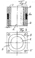
Fig. 2 einen Querschnitt durch einen erfindungsgemäßen Mantelstein; -
Fig. 3 eine Aufsicht auf den inFig. 2 gezeigten Mantelstein von oben (oder unten); -
Fig. 4 einen schematischen Querschnitt durch einen Gebäudeteil im Bereich eines Schornsteins; -
Fig. 5 einen schematischen Querschnitt durch einen Teil des Schornsteins im Bereich der Dachabdeckung und -
Fig. 6 einen Querschnitt durch einen Schornstein unter Verwendung eines erfindungsgemäßen Mantelsteins im Bereich der Dachabdeckung. - Gemäß
Fig. 1 weist der Mantelstein 1 eine sich in Längsrichtung L hinziehende und hier zylindrische Durchbrechung 2 auf. Ringsum die Durchbrechung 2 ist ein Innenrohr 3 als integraler Bestandteil des Mantelsteins 1 geformt; dieses Innenrohr 3 besteht aus Schaumbeton, bei dem die thermische Isolierwirkung durch Lufteinschlüsse im Beton begünstigt ist. Rings um das Innenrohr 3 ist der Mantel 4 ebenfalls als integraler Bestandteils des Mantelsteins 1 geformt. Dieser besteht aus tragfähigem Material, wie Leichtbeton. Längs durch den Mantelstein 1 können in Längsrichtung L weitere Durchbrechungen 5 angeordnet sein, um zusätzliche Verbindungskanäle in Längsrichtung des Schornsteinsystems herzustellen. - In Längsrichtung L ist der Mantelstein 1 hinsichtlich des tragfähigen Materials, 1 wie Leichtbeton, durch einen Trennring 4a unterbrochen. Die Länge 1 dieses Trennrings 4a in Längsrichtung L beträgt bei diesem Beispiel etwa 10 cm. Eine gleiche Längsausstreckung weisen die zum Trennring 4a benachbarten Teile des Mantels 4 aus tragfähigem Material auf.
- Aus
Fig. 2 ergibt sich, dass sich der Trennring 4a über den gesamten Querschnitt des Mantels 4 hinsichtlich seiner Dicke d erstreckt. - Gemäß
Fig. 4 ist innerhalb des Gebäudes 6 in senkrechter Längsrichtung L ein Schornsteinsystem 7 über mehrere Etagen bis über die Gebäudeabdeckung 8 hinaus aufgebaut. Dabei wird das hier nicht gezeigte Innenrohr von einzelnen Mantelsteinen 1 nach außen umgeben. An der Stelle X der Durchbrechung durch die Gebäudeabdeckung 8 befindet sich ein erfindungsgemäßer Mantelstein mit dem hier nicht gezeichneten Trennring. Dieser Mantelstein an der Stelle X ist innerhalb des Schornsteinkopfes 9 und noch ein Stück unterhalb desselben von einem manschettenförmigen Außenmantel 10 aus gleichfalls wärmedämmendem Material umgeben, wie dies noch besser anhand vonFig. 5 illustriert wird. - In dem Querschnittsbild von
Fig. 6 durch einen Teil des Schornsteinsystems befindet sich der erfindungsgemäße Mantelstein 1 mit dem Trennring 4a im Bereich X der hier nicht dargestellten Dachdurchbrechung. Innerhalb der übereinander gesetzten Mantelsteine 1 ist durch deren Durchbrechung 2 ein durchgehendes, insbesondere außen profiliertes Innenrohr 11 verlegt. Am oberen Ende des hier dargestellten Innenrohres 11 ist ein ringförmiger Abstandhalter 12 gezeigt, in den ein weiteres hier nicht gezeigtes Innenrohr eingesteckt werden kann und der gleichzeitig als Abstandhalter zum Zentrieren des Innenrohrs 11 innerhalb der Durchbrechung 2 verwendet werden kann.
Claims (6)
- Mantelstein für Schornsteinsysteme, mit mindestens einer insbesondere zylindrischen Durchbrechung (2) zur Aufnahme eines Innenrohrs (11), bei dem die Innenwand (3) des Mantelsteins (1) rings um die Durchbrechung (2) aus wärmedämmenden Material besteht und dieses insbesondere radial nach außen von einem Mantel (4) aus tragfähigem Material, wie Leichtbeton, umgeben ist,
dadurch gekennzeichnet,
dass der Mantel (4) in Längsrichtung (L) der Durchbrechung (2) mit einem wärmedämmenden, das tragfähige Material trennenden Trennring (4a) versehen ist. - Mantelstein nach Anspruch 1,
dadurch gekennzeichnet,
dass der Trennring (4a) aus geschäumtem Glasmaterial, wie foam glass, besteht. - Mantelstein nach Anspruch 1 oder 2,
dadurch gekennzeichnet,
dass die Länge (1) des Trennrings (4a) zwischen 5 und 15 cm beträgt. - Mantelstein nach einem der vorhergehenden Ansprüche,
dadurch gekennzeichnet,
dass die Dicke (d) des Trennrings etwa gleich dick wie der Mantel (4) ausgebildet ist. - Verwendung eines Mantelsteins nach einem der vorhergehenden Ansprüchen zum Einbau im Durchgangsbereich (X) des Schornsteins durch eine Gebäudeabdeckung (8).
- Verwendung (8) nach Anspruch 5 zum Einbau teilweise innerhalb eines den Mantelstein (1) teilweise überragenden wärmedämmenden Außenmantels (10).
Priority Applications (1)
| Application Number | Priority Date | Filing Date | Title |
|---|---|---|---|
| PL08007922T PL1990481T3 (pl) | 2007-05-10 | 2008-04-24 | Kształtka pierścieniowa do budowy systemów kominowych |
Applications Claiming Priority (1)
| Application Number | Priority Date | Filing Date | Title |
|---|---|---|---|
| DE102007021894A DE102007021894B4 (de) | 2007-05-10 | 2007-05-10 | Mantelstein für Schornsteinsysteme |
Publications (3)
| Publication Number | Publication Date |
|---|---|
| EP1990481A2 true EP1990481A2 (de) | 2008-11-12 |
| EP1990481A3 EP1990481A3 (de) | 2009-05-13 |
| EP1990481B1 EP1990481B1 (de) | 2013-08-07 |
Family
ID=39687934
Family Applications (1)
| Application Number | Title | Priority Date | Filing Date |
|---|---|---|---|
| EP08007922.1A Active EP1990481B1 (de) | 2007-05-10 | 2008-04-24 | Mantelstein für Schornsteinsysteme |
Country Status (3)
| Country | Link |
|---|---|
| EP (1) | EP1990481B1 (de) |
| DE (1) | DE102007021894B4 (de) |
| PL (1) | PL1990481T3 (de) |
Cited By (4)
| Publication number | Priority date | Publication date | Assignee | Title |
|---|---|---|---|---|
| CN101962992A (zh) * | 2010-09-19 | 2011-02-02 | 池州轻型建材有限公司 | 一种排气道及其生产方法 |
| CN102071790A (zh) * | 2010-12-02 | 2011-05-25 | 王晓东 | 节能型组合式排烟气道 |
| CN102108781A (zh) * | 2010-12-29 | 2011-06-29 | 潘长锦 | 楼房用集中排气管道及其用途 |
| CN110756729A (zh) * | 2019-10-17 | 2020-02-07 | 吉林省诚鼎精密铸造有限公司 | 汽车模具泡沫模型起吊孔的加工制作方法 |
Citations (4)
| Publication number | Priority date | Publication date | Assignee | Title |
|---|---|---|---|---|
| DE2032689A1 (de) | 1970-07-02 | 1972-01-05 | Tonwerke Schmitz GmbH, 5351 Antwei- | Schornstein |
| DE2415281A1 (de) | 1974-03-29 | 1975-10-09 | Hans Grille | Fugendichtung fuer schornstein - fertigelemente |
| DE8913493U1 (de) | 1988-12-23 | 1990-01-18 | Delta-Wohnbau GmbH, 7913 Senden | Kaminrohr |
| EP0874107B1 (de) | 1997-04-21 | 2003-11-19 | Imerys Toiture | Tonkörperrohrelement zur Herstellung von Rauchgasabzugsrohren |
Family Cites Families (9)
| Publication number | Priority date | Publication date | Assignee | Title |
|---|---|---|---|---|
| US1603968A (en) * | 1925-11-17 | 1926-10-19 | John F Metten | Heat-insulating structure |
| DE1950362U (de) * | 1966-06-20 | 1966-11-24 | Hans Anger | Kaminfertigelement fuer hausschornsteine und staerkere feuerungsanlagen. |
| AT369477B (de) * | 1980-09-16 | 1983-01-10 | Mario Sottopietra | Fertigteil fuer kamine |
| AT374873B (de) * | 1982-06-11 | 1984-06-12 | Betonwerk Neunkirchen Ges M B | Fang, insbesondere rauchfang |
| DE8520590U1 (de) * | 1985-07-17 | 1985-09-26 | Union-Bau Frankfurt GmbH, 6052 Mühlheim | Mantelstein für mehrschalige Schornsteine |
| DE3736723A1 (de) * | 1987-10-29 | 1989-05-11 | Otavi Minen Ag | Mehrschaliger schornstein |
| AT400347B (de) * | 1993-03-25 | 1995-12-27 | Schiedel Kaminwerke Gmbh | Schornstein |
| CH690133A5 (de) * | 1995-03-07 | 2000-05-15 | Stefan Schmid | Ausrollung für ein Metallkaminrohr. |
| ATE183798T1 (de) * | 1998-02-02 | 1999-09-15 | Schiedel Kaminwerke Gmbh | Mantelstein für einen mehrschaligen kamin |
-
2007
- 2007-05-10 DE DE102007021894A patent/DE102007021894B4/de not_active Expired - Fee Related
-
2008
- 2008-04-24 PL PL08007922T patent/PL1990481T3/pl unknown
- 2008-04-24 EP EP08007922.1A patent/EP1990481B1/de active Active
Patent Citations (4)
| Publication number | Priority date | Publication date | Assignee | Title |
|---|---|---|---|---|
| DE2032689A1 (de) | 1970-07-02 | 1972-01-05 | Tonwerke Schmitz GmbH, 5351 Antwei- | Schornstein |
| DE2415281A1 (de) | 1974-03-29 | 1975-10-09 | Hans Grille | Fugendichtung fuer schornstein - fertigelemente |
| DE8913493U1 (de) | 1988-12-23 | 1990-01-18 | Delta-Wohnbau GmbH, 7913 Senden | Kaminrohr |
| EP0874107B1 (de) | 1997-04-21 | 2003-11-19 | Imerys Toiture | Tonkörperrohrelement zur Herstellung von Rauchgasabzugsrohren |
Cited By (5)
| Publication number | Priority date | Publication date | Assignee | Title |
|---|---|---|---|---|
| CN101962992A (zh) * | 2010-09-19 | 2011-02-02 | 池州轻型建材有限公司 | 一种排气道及其生产方法 |
| CN102071790A (zh) * | 2010-12-02 | 2011-05-25 | 王晓东 | 节能型组合式排烟气道 |
| CN102108781A (zh) * | 2010-12-29 | 2011-06-29 | 潘长锦 | 楼房用集中排气管道及其用途 |
| CN110756729A (zh) * | 2019-10-17 | 2020-02-07 | 吉林省诚鼎精密铸造有限公司 | 汽车模具泡沫模型起吊孔的加工制作方法 |
| CN110756729B (zh) * | 2019-10-17 | 2020-12-29 | 吉林省诚鼎精密铸造有限公司 | 汽车模具泡沫模型起吊孔的加工制作方法 |
Also Published As
| Publication number | Publication date |
|---|---|
| EP1990481B1 (de) | 2013-08-07 |
| DE102007021894B4 (de) | 2009-10-01 |
| EP1990481A3 (de) | 2009-05-13 |
| PL1990481T3 (pl) | 2013-12-31 |
| DE102007021894A1 (de) | 2008-11-20 |
Similar Documents
| Publication | Publication Date | Title |
|---|---|---|
| EP1990481B1 (de) | Mantelstein für Schornsteinsysteme | |
| DE202009019012U1 (de) | Skelettbau für ein Gebäude | |
| DE2203822A1 (de) | Verschmutzungsfreier Schornstein | |
| DE1922581C3 (de) | Kamin aus Fertigteilen | |
| DE19608702A1 (de) | Wandkonstruktion | |
| EP0209815A2 (de) | Mantelstein für mehrschalige Schornsteine | |
| DE3317266A1 (de) | Fang, insbesondere rauchfang, sowie formstein zur herstellung desselben | |
| DE19538536B4 (de) | Fertig-Kondensationskamin insbesondere für Heizanlagen mit niedriger Abgastemperatur | |
| EP1503143B1 (de) | Hinterlüfteter Kamin | |
| CH670858A5 (de) | ||
| DE1815516C3 (de) | Durchgehende Isolationsschicht aus Mineralfasern eines Schornsteins oder Schornsteinformstücks, Schornsteinkopf und Schornsteinformstück mit einer solchen Isolationsschicht, Verfahren zum nachträglichen Einbringen einer solchen Isolationsschicht sowie Anwendungen dieses Verfahrens | |
| DE3317308C2 (de) | Schornsteinstück mit Anschlußmöglichkeit an mindestens eine Einzelfeuerung | |
| DE19616268C2 (de) | Vorrichtung zur Führung und Ausleitung von durch eine, in einem Gebäude zu Heizzwecken installierte Verbrennungseinrichtung | |
| EP1988318B1 (de) | Wanddurchführung | |
| DE102007010910A1 (de) | Vorrichtung zur Ableitung von Verbrennungsabgasen aus einem Gebäude | |
| EP0906995B1 (de) | Mantelstein für einen mehrschaligen Kamin | |
| DE8429277U1 (de) | Mehrschaliger Schornstein | |
| DE8913493U1 (de) | Kaminrohr | |
| DE3402612A1 (de) | Mehrschaliger kamin aus fertigteilen | |
| EP1532397B1 (de) | VORRICHTUNG ZUR FüHRUNG UND AUSLEITUNG VON ABLUFT | |
| DE862662C (de) | Bauweise | |
| DE1922389C3 (de) | Mehrschaliges Kaminfertigteil | |
| DE29616563U1 (de) | Schacht für Abgasanlagen in Gebäuden und Bauelemente zu dessen Herstellung | |
| CH488078A (de) | Kaminfertigteil | |
| DE3942154A1 (de) | Fertigkamin aus gas- oder schaumbeton und verfahren zu seiner herstellung |
Legal Events
| Date | Code | Title | Description |
|---|---|---|---|
| PUAI | Public reference made under article 153(3) epc to a published international application that has entered the european phase |
Free format text: ORIGINAL CODE: 0009012 |
|
| AK | Designated contracting states |
Kind code of ref document: A2 Designated state(s): AT BE BG CH CY CZ DE DK EE ES FI FR GB GR HR HU IE IS IT LI LT LU LV MC MT NL NO PL PT RO SE SI SK TR |
|
| AX | Request for extension of the european patent |
Extension state: AL BA MK RS |
|
| PUAL | Search report despatched |
Free format text: ORIGINAL CODE: 0009013 |
|
| AK | Designated contracting states |
Kind code of ref document: A3 Designated state(s): AT BE BG CH CY CZ DE DK EE ES FI FR GB GR HR HU IE IS IT LI LT LU LV MC MT NL NO PL PT RO SE SI SK TR |
|
| AX | Request for extension of the european patent |
Extension state: AL BA MK RS |
|
| 17P | Request for examination filed |
Effective date: 20090821 |
|
| AKX | Designation fees paid |
Designated state(s): AT BE BG CH CY CZ DE DK EE ES FI FR GB GR HR HU IE IS IT LI LT LU LV MC MT NL NO PL PT RO SE SI SK TR |
|
| GRAP | Despatch of communication of intention to grant a patent |
Free format text: ORIGINAL CODE: EPIDOSNIGR1 |
|
| GRAS | Grant fee paid |
Free format text: ORIGINAL CODE: EPIDOSNIGR3 |
|
| GRAA | (expected) grant |
Free format text: ORIGINAL CODE: 0009210 |
|
| AK | Designated contracting states |
Kind code of ref document: B1 Designated state(s): AT BE BG CH CY CZ DE DK EE ES FI FR GB GR HR HU IE IS IT LI LT LU LV MC MT NL NO PL PT RO SE SI SK TR |
|
| REG | Reference to a national code |
Ref country code: GB Ref legal event code: FG4D Free format text: NOT ENGLISH |
|
| REG | Reference to a national code |
Ref country code: CH Ref legal event code: EP Ref country code: AT Ref legal event code: REF Ref document number: 625855 Country of ref document: AT Kind code of ref document: T Effective date: 20130815 |
|
| REG | Reference to a national code |
Ref country code: IE Ref legal event code: FG4D Free format text: LANGUAGE OF EP DOCUMENT: GERMAN |
|
| REG | Reference to a national code |
Ref country code: DE Ref legal event code: R096 Ref document number: 502008010431 Country of ref document: DE Effective date: 20131010 |
|
| REG | Reference to a national code |
Ref country code: SK Ref legal event code: T3 Ref document number: E 14840 Country of ref document: SK |
|
| REG | Reference to a national code |
Ref country code: PL Ref legal event code: T3 |
|
| REG | Reference to a national code |
Ref country code: NL Ref legal event code: VDEP Effective date: 20130807 |
|
| REG | Reference to a national code |
Ref country code: LT Ref legal event code: MG4D |
|
| PG25 | Lapsed in a contracting state [announced via postgrant information from national office to epo] |
Ref country code: HR Free format text: LAPSE BECAUSE OF FAILURE TO SUBMIT A TRANSLATION OF THE DESCRIPTION OR TO PAY THE FEE WITHIN THE PRESCRIBED TIME-LIMIT Effective date: 20130807 Ref country code: LT Free format text: LAPSE BECAUSE OF FAILURE TO SUBMIT A TRANSLATION OF THE DESCRIPTION OR TO PAY THE FEE WITHIN THE PRESCRIBED TIME-LIMIT Effective date: 20130807 Ref country code: CY Free format text: LAPSE BECAUSE OF FAILURE TO SUBMIT A TRANSLATION OF THE DESCRIPTION OR TO PAY THE FEE WITHIN THE PRESCRIBED TIME-LIMIT Effective date: 20130619 Ref country code: IS Free format text: LAPSE BECAUSE OF FAILURE TO SUBMIT A TRANSLATION OF THE DESCRIPTION OR TO PAY THE FEE WITHIN THE PRESCRIBED TIME-LIMIT Effective date: 20131207 Ref country code: SE Free format text: LAPSE BECAUSE OF FAILURE TO SUBMIT A TRANSLATION OF THE DESCRIPTION OR TO PAY THE FEE WITHIN THE PRESCRIBED TIME-LIMIT Effective date: 20130807 Ref country code: NO Free format text: LAPSE BECAUSE OF FAILURE TO SUBMIT A TRANSLATION OF THE DESCRIPTION OR TO PAY THE FEE WITHIN THE PRESCRIBED TIME-LIMIT Effective date: 20131107 Ref country code: PT Free format text: LAPSE BECAUSE OF FAILURE TO SUBMIT A TRANSLATION OF THE DESCRIPTION OR TO PAY THE FEE WITHIN THE PRESCRIBED TIME-LIMIT Effective date: 20131209 |
|
| PG25 | Lapsed in a contracting state [announced via postgrant information from national office to epo] |
Ref country code: ES Free format text: LAPSE BECAUSE OF FAILURE TO SUBMIT A TRANSLATION OF THE DESCRIPTION OR TO PAY THE FEE WITHIN THE PRESCRIBED TIME-LIMIT Effective date: 20130807 Ref country code: FI Free format text: LAPSE BECAUSE OF FAILURE TO SUBMIT A TRANSLATION OF THE DESCRIPTION OR TO PAY THE FEE WITHIN THE PRESCRIBED TIME-LIMIT Effective date: 20130807 Ref country code: GR Free format text: LAPSE BECAUSE OF FAILURE TO SUBMIT A TRANSLATION OF THE DESCRIPTION OR TO PAY THE FEE WITHIN THE PRESCRIBED TIME-LIMIT Effective date: 20131108 Ref country code: NL Free format text: LAPSE BECAUSE OF FAILURE TO SUBMIT A TRANSLATION OF THE DESCRIPTION OR TO PAY THE FEE WITHIN THE PRESCRIBED TIME-LIMIT Effective date: 20130807 Ref country code: SI Free format text: LAPSE BECAUSE OF FAILURE TO SUBMIT A TRANSLATION OF THE DESCRIPTION OR TO PAY THE FEE WITHIN THE PRESCRIBED TIME-LIMIT Effective date: 20130807 Ref country code: LV Free format text: LAPSE BECAUSE OF FAILURE TO SUBMIT A TRANSLATION OF THE DESCRIPTION OR TO PAY THE FEE WITHIN THE PRESCRIBED TIME-LIMIT Effective date: 20130807 |
|
| PG25 | Lapsed in a contracting state [announced via postgrant information from national office to epo] |
Ref country code: CY Free format text: LAPSE BECAUSE OF FAILURE TO SUBMIT A TRANSLATION OF THE DESCRIPTION OR TO PAY THE FEE WITHIN THE PRESCRIBED TIME-LIMIT Effective date: 20130807 |
|
| PG25 | Lapsed in a contracting state [announced via postgrant information from national office to epo] |
Ref country code: RO Free format text: LAPSE BECAUSE OF FAILURE TO SUBMIT A TRANSLATION OF THE DESCRIPTION OR TO PAY THE FEE WITHIN THE PRESCRIBED TIME-LIMIT Effective date: 20130807 Ref country code: EE Free format text: LAPSE BECAUSE OF FAILURE TO SUBMIT A TRANSLATION OF THE DESCRIPTION OR TO PAY THE FEE WITHIN THE PRESCRIBED TIME-LIMIT Effective date: 20130807 Ref country code: DK Free format text: LAPSE BECAUSE OF FAILURE TO SUBMIT A TRANSLATION OF THE DESCRIPTION OR TO PAY THE FEE WITHIN THE PRESCRIBED TIME-LIMIT Effective date: 20130807 |
|
| PG25 | Lapsed in a contracting state [announced via postgrant information from national office to epo] |
Ref country code: IT Free format text: LAPSE BECAUSE OF FAILURE TO SUBMIT A TRANSLATION OF THE DESCRIPTION OR TO PAY THE FEE WITHIN THE PRESCRIBED TIME-LIMIT Effective date: 20130807 |
|
| PLBE | No opposition filed within time limit |
Free format text: ORIGINAL CODE: 0009261 |
|
| STAA | Information on the status of an ep patent application or granted ep patent |
Free format text: STATUS: NO OPPOSITION FILED WITHIN TIME LIMIT |
|
| 26N | No opposition filed |
Effective date: 20140508 |
|
| REG | Reference to a national code |
Ref country code: DE Ref legal event code: R097 Ref document number: 502008010431 Country of ref document: DE Effective date: 20140508 |
|
| PG25 | Lapsed in a contracting state [announced via postgrant information from national office to epo] |
Ref country code: MC Free format text: LAPSE BECAUSE OF FAILURE TO SUBMIT A TRANSLATION OF THE DESCRIPTION OR TO PAY THE FEE WITHIN THE PRESCRIBED TIME-LIMIT Effective date: 20130807 Ref country code: LU Free format text: LAPSE BECAUSE OF FAILURE TO SUBMIT A TRANSLATION OF THE DESCRIPTION OR TO PAY THE FEE WITHIN THE PRESCRIBED TIME-LIMIT Effective date: 20140424 |
|
| REG | Reference to a national code |
Ref country code: CH Ref legal event code: PL |
|
| GBPC | Gb: european patent ceased through non-payment of renewal fee |
Effective date: 20140424 |
|
| REG | Reference to a national code |
Ref country code: FR Ref legal event code: ST Effective date: 20141231 |
|
| REG | Reference to a national code |
Ref country code: IE Ref legal event code: MM4A |
|
| PG25 | Lapsed in a contracting state [announced via postgrant information from national office to epo] |
Ref country code: GB Free format text: LAPSE BECAUSE OF NON-PAYMENT OF DUE FEES Effective date: 20140424 Ref country code: LI Free format text: LAPSE BECAUSE OF NON-PAYMENT OF DUE FEES Effective date: 20140430 Ref country code: CH Free format text: LAPSE BECAUSE OF NON-PAYMENT OF DUE FEES Effective date: 20140430 |
|
| PG25 | Lapsed in a contracting state [announced via postgrant information from national office to epo] |
Ref country code: FR Free format text: LAPSE BECAUSE OF NON-PAYMENT OF DUE FEES Effective date: 20140430 |
|
| PG25 | Lapsed in a contracting state [announced via postgrant information from national office to epo] |
Ref country code: IE Free format text: LAPSE BECAUSE OF NON-PAYMENT OF DUE FEES Effective date: 20140424 |
|
| PG25 | Lapsed in a contracting state [announced via postgrant information from national office to epo] |
Ref country code: MT Free format text: LAPSE BECAUSE OF FAILURE TO SUBMIT A TRANSLATION OF THE DESCRIPTION OR TO PAY THE FEE WITHIN THE PRESCRIBED TIME-LIMIT Effective date: 20130807 |
|
| PG25 | Lapsed in a contracting state [announced via postgrant information from national office to epo] |
Ref country code: BG Free format text: LAPSE BECAUSE OF FAILURE TO SUBMIT A TRANSLATION OF THE DESCRIPTION OR TO PAY THE FEE WITHIN THE PRESCRIBED TIME-LIMIT Effective date: 20130807 |
|
| PG25 | Lapsed in a contracting state [announced via postgrant information from national office to epo] |
Ref country code: TR Free format text: LAPSE BECAUSE OF FAILURE TO SUBMIT A TRANSLATION OF THE DESCRIPTION OR TO PAY THE FEE WITHIN THE PRESCRIBED TIME-LIMIT Effective date: 20130807 Ref country code: BE Free format text: LAPSE BECAUSE OF FAILURE TO SUBMIT A TRANSLATION OF THE DESCRIPTION OR TO PAY THE FEE WITHIN THE PRESCRIBED TIME-LIMIT Effective date: 20140430 Ref country code: HU Free format text: LAPSE BECAUSE OF FAILURE TO SUBMIT A TRANSLATION OF THE DESCRIPTION OR TO PAY THE FEE WITHIN THE PRESCRIBED TIME-LIMIT; INVALID AB INITIO Effective date: 20080424 |
|
| P01 | Opt-out of the competence of the unified patent court (upc) registered |
Effective date: 20230516 |
|
| PGFP | Annual fee paid to national office [announced via postgrant information from national office to epo] |
Ref country code: PL Payment date: 20250414 Year of fee payment: 18 Ref country code: DE Payment date: 20250417 Year of fee payment: 18 |
|
| PGFP | Annual fee paid to national office [announced via postgrant information from national office to epo] |
Ref country code: AT Payment date: 20250416 Year of fee payment: 18 |
|
| PGFP | Annual fee paid to national office [announced via postgrant information from national office to epo] |
Ref country code: SK Payment date: 20250422 Year of fee payment: 18 |
|
| PGFP | Annual fee paid to national office [announced via postgrant information from national office to epo] |
Ref country code: CZ Payment date: 20250411 Year of fee payment: 18 |