EP1990207A1 - Druckverfahren, Druckvorrichtung und gedrucktes Dokument - Google Patents
Druckverfahren, Druckvorrichtung und gedrucktes Dokument Download PDFInfo
- Publication number
- EP1990207A1 EP1990207A1 EP20080155783 EP08155783A EP1990207A1 EP 1990207 A1 EP1990207 A1 EP 1990207A1 EP 20080155783 EP20080155783 EP 20080155783 EP 08155783 A EP08155783 A EP 08155783A EP 1990207 A1 EP1990207 A1 EP 1990207A1
- Authority
- EP
- European Patent Office
- Prior art keywords
- ink
- pressure
- sensitive adhesive
- adhesive layer
- printing
- Prior art date
- Legal status (The legal status is an assumption and is not a legal conclusion. Google has not performed a legal analysis and makes no representation as to the accuracy of the status listed.)
- Granted
Links
- 238000007639 printing Methods 0.000 title claims abstract description 178
- 238000000034 method Methods 0.000 title claims abstract description 55
- 239000004820 Pressure-sensitive adhesive Substances 0.000 claims abstract description 219
- 239000010410 layer Substances 0.000 claims abstract description 134
- 238000007641 inkjet printing Methods 0.000 claims description 24
- 239000007788 liquid Substances 0.000 claims description 24
- 230000001678 irradiating effect Effects 0.000 claims 1
- 239000000976 ink Substances 0.000 description 330
- 239000000049 pigment Substances 0.000 description 48
- 239000003795 chemical substances by application Substances 0.000 description 25
- 239000002585 base Substances 0.000 description 24
- 239000000463 material Substances 0.000 description 21
- 238000001723 curing Methods 0.000 description 17
- 239000012530 fluid Substances 0.000 description 17
- 229920005989 resin Polymers 0.000 description 17
- 239000011347 resin Substances 0.000 description 17
- XLYOFNOQVPJJNP-UHFFFAOYSA-N water Substances O XLYOFNOQVPJJNP-UHFFFAOYSA-N 0.000 description 16
- 238000011156 evaluation Methods 0.000 description 15
- 239000000123 paper Substances 0.000 description 15
- 239000000203 mixture Substances 0.000 description 10
- 230000032258 transport Effects 0.000 description 10
- 239000011248 coating agent Substances 0.000 description 9
- 238000000576 coating method Methods 0.000 description 9
- QSHDDOUJBYECFT-UHFFFAOYSA-N mercury Chemical compound [Hg] QSHDDOUJBYECFT-UHFFFAOYSA-N 0.000 description 9
- 229910052753 mercury Inorganic materials 0.000 description 9
- 239000000178 monomer Substances 0.000 description 9
- 238000011084 recovery Methods 0.000 description 8
- 239000002904 solvent Substances 0.000 description 8
- 239000000126 substance Substances 0.000 description 8
- 239000006229 carbon black Substances 0.000 description 7
- 150000001875 compounds Chemical class 0.000 description 7
- 239000012466 permeate Substances 0.000 description 7
- 239000006185 dispersion Substances 0.000 description 6
- 238000011049 filling Methods 0.000 description 6
- 238000012545 processing Methods 0.000 description 6
- 239000000853 adhesive Substances 0.000 description 5
- 239000003999 initiator Substances 0.000 description 5
- 229920000642 polymer Polymers 0.000 description 5
- 239000007787 solid Substances 0.000 description 5
- PEDCQBHIVMGVHV-UHFFFAOYSA-N Glycerine Chemical compound OCC(O)CO PEDCQBHIVMGVHV-UHFFFAOYSA-N 0.000 description 4
- PPBRXRYQALVLMV-UHFFFAOYSA-N Styrene Chemical compound C=CC1=CC=CC=C1 PPBRXRYQALVLMV-UHFFFAOYSA-N 0.000 description 4
- 239000000654 additive Substances 0.000 description 4
- 230000000996 additive effect Effects 0.000 description 4
- 238000005259 measurement Methods 0.000 description 4
- 239000002245 particle Substances 0.000 description 4
- 230000035699 permeability Effects 0.000 description 4
- BASFCYQUMIYNBI-UHFFFAOYSA-N platinum Chemical compound [Pt] BASFCYQUMIYNBI-UHFFFAOYSA-N 0.000 description 4
- -1 polyethylene Polymers 0.000 description 4
- 238000002360 preparation method Methods 0.000 description 4
- 239000004094 surface-active agent Substances 0.000 description 4
- 238000012546 transfer Methods 0.000 description 4
- VGGSQFUCUMXWEO-UHFFFAOYSA-N Ethene Chemical compound C=C VGGSQFUCUMXWEO-UHFFFAOYSA-N 0.000 description 3
- 239000005977 Ethylene Substances 0.000 description 3
- 238000003848 UV Light-Curing Methods 0.000 description 3
- 238000010521 absorption reaction Methods 0.000 description 3
- 230000015572 biosynthetic process Effects 0.000 description 3
- 238000006243 chemical reaction Methods 0.000 description 3
- 238000004140 cleaning Methods 0.000 description 3
- 238000004891 communication Methods 0.000 description 3
- MTHSVFCYNBDYFN-UHFFFAOYSA-N diethylene glycol Chemical compound OCCOCCO MTHSVFCYNBDYFN-UHFFFAOYSA-N 0.000 description 3
- 150000002148 esters Chemical class 0.000 description 3
- 230000006870 function Effects 0.000 description 3
- 239000012535 impurity Substances 0.000 description 3
- 238000005342 ion exchange Methods 0.000 description 3
- 229910052751 metal Inorganic materials 0.000 description 3
- 239000002184 metal Substances 0.000 description 3
- 238000007645 offset printing Methods 0.000 description 3
- SMZOUWXMTYCWNB-UHFFFAOYSA-N 2-(2-methoxy-5-methylphenyl)ethanamine Chemical compound COC1=CC=C(C)C=C1CCN SMZOUWXMTYCWNB-UHFFFAOYSA-N 0.000 description 2
- LEJBBGNFPAFPKQ-UHFFFAOYSA-N 2-(2-prop-2-enoyloxyethoxy)ethyl prop-2-enoate Chemical compound C=CC(=O)OCCOCCOC(=O)C=C LEJBBGNFPAFPKQ-UHFFFAOYSA-N 0.000 description 2
- NIXOWILDQLNWCW-UHFFFAOYSA-N 2-Propenoic acid Natural products OC(=O)C=C NIXOWILDQLNWCW-UHFFFAOYSA-N 0.000 description 2
- INQDDHNZXOAFFD-UHFFFAOYSA-N 2-[2-(2-prop-2-enoyloxyethoxy)ethoxy]ethyl prop-2-enoate Chemical compound C=CC(=O)OCCOCCOCCOC(=O)C=C INQDDHNZXOAFFD-UHFFFAOYSA-N 0.000 description 2
- HCLJOFJIQIJXHS-UHFFFAOYSA-N 2-[2-[2-(2-prop-2-enoyloxyethoxy)ethoxy]ethoxy]ethyl prop-2-enoate Chemical compound C=CC(=O)OCCOCCOCCOCCOC(=O)C=C HCLJOFJIQIJXHS-UHFFFAOYSA-N 0.000 description 2
- KUDUQBURMYMBIJ-UHFFFAOYSA-N 2-prop-2-enoyloxyethyl prop-2-enoate Chemical compound C=CC(=O)OCCOC(=O)C=C KUDUQBURMYMBIJ-UHFFFAOYSA-N 0.000 description 2
- NIXOWILDQLNWCW-UHFFFAOYSA-M Acrylate Chemical compound [O-]C(=O)C=C NIXOWILDQLNWCW-UHFFFAOYSA-M 0.000 description 2
- SOGAXMICEFXMKE-UHFFFAOYSA-N Butylmethacrylate Chemical compound CCCCOC(=O)C(C)=C SOGAXMICEFXMKE-UHFFFAOYSA-N 0.000 description 2
- LYCAIKOWRPUZTN-UHFFFAOYSA-N Ethylene glycol Chemical compound OCCO LYCAIKOWRPUZTN-UHFFFAOYSA-N 0.000 description 2
- 244000043261 Hevea brasiliensis Species 0.000 description 2
- BAPJBEWLBFYGME-UHFFFAOYSA-N Methyl acrylate Chemical compound COC(=O)C=C BAPJBEWLBFYGME-UHFFFAOYSA-N 0.000 description 2
- 229920002433 Vinyl chloride-vinyl acetate copolymer Polymers 0.000 description 2
- 230000001464 adherent effect Effects 0.000 description 2
- 230000003064 anti-oxidating effect Effects 0.000 description 2
- 239000004599 antimicrobial Substances 0.000 description 2
- 150000001767 cationic compounds Chemical class 0.000 description 2
- 230000008859 change Effects 0.000 description 2
- 229920001577 copolymer Polymers 0.000 description 2
- 239000004148 curcumin Substances 0.000 description 2
- 238000001514 detection method Methods 0.000 description 2
- 238000011161 development Methods 0.000 description 2
- 238000010586 diagram Methods 0.000 description 2
- 238000009792 diffusion process Methods 0.000 description 2
- 239000002270 dispersing agent Substances 0.000 description 2
- 238000001035 drying Methods 0.000 description 2
- 238000000295 emission spectrum Methods 0.000 description 2
- QFXZANXYUCUTQH-UHFFFAOYSA-N ethynol Chemical compound OC#C QFXZANXYUCUTQH-UHFFFAOYSA-N 0.000 description 2
- 239000004744 fabric Substances 0.000 description 2
- 230000002349 favourable effect Effects 0.000 description 2
- 239000006260 foam Substances 0.000 description 2
- 230000004927 fusion Effects 0.000 description 2
- 235000011187 glycerol Nutrition 0.000 description 2
- 238000007646 gravure printing Methods 0.000 description 2
- 150000002576 ketones Chemical class 0.000 description 2
- 229920003052 natural elastomer Polymers 0.000 description 2
- 229920001194 natural rubber Polymers 0.000 description 2
- 239000003921 oil Substances 0.000 description 2
- 239000003960 organic solvent Substances 0.000 description 2
- 239000002985 plastic film Substances 0.000 description 2
- 229920006255 plastic film Polymers 0.000 description 2
- 229910052697 platinum Inorganic materials 0.000 description 2
- 239000002952 polymeric resin Substances 0.000 description 2
- 230000008569 process Effects 0.000 description 2
- 238000010526 radical polymerization reaction Methods 0.000 description 2
- 229920003002 synthetic resin Polymers 0.000 description 2
- LDHQCZJRKDOVOX-UHFFFAOYSA-N trans-crotonic acid Natural products CC=CC(O)=O LDHQCZJRKDOVOX-UHFFFAOYSA-N 0.000 description 2
- 238000009281 ultraviolet germicidal irradiation Methods 0.000 description 2
- MJQHDSIEDGPFAM-UHFFFAOYSA-N (3-benzoylphenyl)-phenylmethanone Chemical compound C=1C=CC(C(=O)C=2C=CC=CC=2)=CC=1C(=O)C1=CC=CC=C1 MJQHDSIEDGPFAM-UHFFFAOYSA-N 0.000 description 1
- UUGXDEDGRPYWHG-UHFFFAOYSA-N (dimethylamino)methyl 2-methylprop-2-enoate Chemical compound CN(C)COC(=O)C(C)=C UUGXDEDGRPYWHG-UHFFFAOYSA-N 0.000 description 1
- MYWOJODOMFBVCB-UHFFFAOYSA-N 1,2,6-trimethylphenanthrene Chemical compound CC1=CC=C2C3=CC(C)=CC=C3C=CC2=C1C MYWOJODOMFBVCB-UHFFFAOYSA-N 0.000 description 1
- DKEGCUDAFWNSSO-UHFFFAOYSA-N 1,8-dibromooctane Chemical compound BrCCCCCCCCBr DKEGCUDAFWNSSO-UHFFFAOYSA-N 0.000 description 1
- 239000012956 1-hydroxycyclohexylphenyl-ketone Substances 0.000 description 1
- GZBSIABKXVPBFY-UHFFFAOYSA-N 2,2-bis(hydroxymethyl)propane-1,3-diol;prop-2-enoic acid Chemical compound OC(=O)C=C.OC(=O)C=C.OC(=O)C=C.OC(=O)C=C.OCC(CO)(CO)CO GZBSIABKXVPBFY-UHFFFAOYSA-N 0.000 description 1
- BTJPUDCSZVCXFQ-UHFFFAOYSA-N 2,4-diethylthioxanthen-9-one Chemical compound C1=CC=C2C(=O)C3=CC(CC)=CC(CC)=C3SC2=C1 BTJPUDCSZVCXFQ-UHFFFAOYSA-N 0.000 description 1
- FTALTLPZDVFJSS-UHFFFAOYSA-N 2-(2-ethoxyethoxy)ethyl prop-2-enoate Chemical compound CCOCCOCCOC(=O)C=C FTALTLPZDVFJSS-UHFFFAOYSA-N 0.000 description 1
- JAHNSTQSQJOJLO-UHFFFAOYSA-N 2-(3-fluorophenyl)-1h-imidazole Chemical compound FC1=CC=CC(C=2NC=CN=2)=C1 JAHNSTQSQJOJLO-UHFFFAOYSA-N 0.000 description 1
- QHVBLSNVXDSMEB-UHFFFAOYSA-N 2-(diethylamino)ethyl prop-2-enoate Chemical compound CCN(CC)CCOC(=O)C=C QHVBLSNVXDSMEB-UHFFFAOYSA-N 0.000 description 1
- DPBJAVGHACCNRL-UHFFFAOYSA-N 2-(dimethylamino)ethyl prop-2-enoate Chemical compound CN(C)CCOC(=O)C=C DPBJAVGHACCNRL-UHFFFAOYSA-N 0.000 description 1
- GOXQRTZXKQZDDN-UHFFFAOYSA-N 2-Ethylhexyl acrylate Chemical compound CCCCC(CC)COC(=O)C=C GOXQRTZXKQZDDN-UHFFFAOYSA-N 0.000 description 1
- TXBCBTDQIULDIA-UHFFFAOYSA-N 2-[[3-hydroxy-2,2-bis(hydroxymethyl)propoxy]methyl]-2-(hydroxymethyl)propane-1,3-diol Chemical compound OCC(CO)(CO)COCC(CO)(CO)CO TXBCBTDQIULDIA-UHFFFAOYSA-N 0.000 description 1
- POAOYUHQDCAZBD-UHFFFAOYSA-N 2-butoxyethanol Chemical compound CCCCOCCO POAOYUHQDCAZBD-UHFFFAOYSA-N 0.000 description 1
- PTJDGKYFJYEAOK-UHFFFAOYSA-N 2-butoxyethyl prop-2-enoate Chemical compound CCCCOCCOC(=O)C=C PTJDGKYFJYEAOK-UHFFFAOYSA-N 0.000 description 1
- KMNCBSZOIQAUFX-UHFFFAOYSA-N 2-ethoxy-1,2-diphenylethanone Chemical compound C=1C=CC=CC=1C(OCC)C(=O)C1=CC=CC=C1 KMNCBSZOIQAUFX-UHFFFAOYSA-N 0.000 description 1
- WDQMWEYDKDCEHT-UHFFFAOYSA-N 2-ethylhexyl 2-methylprop-2-enoate Chemical compound CCCCC(CC)COC(=O)C(C)=C WDQMWEYDKDCEHT-UHFFFAOYSA-N 0.000 description 1
- QPXVRLXJHPTCPW-UHFFFAOYSA-N 2-hydroxy-2-methyl-1-(4-propan-2-ylphenyl)propan-1-one Chemical compound CC(C)C1=CC=C(C(=O)C(C)(C)O)C=C1 QPXVRLXJHPTCPW-UHFFFAOYSA-N 0.000 description 1
- XMLYCEVDHLAQEL-UHFFFAOYSA-N 2-hydroxy-2-methyl-1-phenylpropan-1-one Chemical compound CC(C)(O)C(=O)C1=CC=CC=C1 XMLYCEVDHLAQEL-UHFFFAOYSA-N 0.000 description 1
- OMIGHNLMNHATMP-UHFFFAOYSA-N 2-hydroxyethyl prop-2-enoate Chemical compound OCCOC(=O)C=C OMIGHNLMNHATMP-UHFFFAOYSA-N 0.000 description 1
- KXGFMDJXCMQABM-UHFFFAOYSA-N 2-methoxy-6-methylphenol Chemical compound [CH]OC1=CC=CC([CH])=C1O KXGFMDJXCMQABM-UHFFFAOYSA-N 0.000 description 1
- LWRBVKNFOYUCNP-UHFFFAOYSA-N 2-methyl-1-(4-methylsulfanylphenyl)-2-morpholin-4-ylpropan-1-one Chemical compound C1=CC(SC)=CC=C1C(=O)C(C)(C)N1CCOCC1 LWRBVKNFOYUCNP-UHFFFAOYSA-N 0.000 description 1
- RZVINYQDSSQUKO-UHFFFAOYSA-N 2-phenoxyethyl prop-2-enoate Chemical compound C=CC(=O)OCCOC1=CC=CC=C1 RZVINYQDSSQUKO-UHFFFAOYSA-N 0.000 description 1
- KTALPKYXQZGAEG-UHFFFAOYSA-N 2-propan-2-ylthioxanthen-9-one Chemical compound C1=CC=C2C(=O)C3=CC(C(C)C)=CC=C3SC2=C1 KTALPKYXQZGAEG-UHFFFAOYSA-N 0.000 description 1
- CYXODUIWJAVDAK-UHFFFAOYSA-N 3-(oxiran-2-yl)propyl prop-2-enoate Chemical compound C=CC(=O)OCCCC1CO1 CYXODUIWJAVDAK-UHFFFAOYSA-N 0.000 description 1
- FQMIAEWUVYWVNB-UHFFFAOYSA-N 3-prop-2-enoyloxybutyl prop-2-enoate Chemical compound C=CC(=O)OC(C)CCOC(=O)C=C FQMIAEWUVYWVNB-UHFFFAOYSA-N 0.000 description 1
- JHWGFJBTMHEZME-UHFFFAOYSA-N 4-prop-2-enoyloxybutyl prop-2-enoate Chemical compound C=CC(=O)OCCCCOC(=O)C=C JHWGFJBTMHEZME-UHFFFAOYSA-N 0.000 description 1
- FIHBHSQYSYVZQE-UHFFFAOYSA-N 6-prop-2-enoyloxyhexyl prop-2-enoate Chemical compound C=CC(=O)OCCCCCCOC(=O)C=C FIHBHSQYSYVZQE-UHFFFAOYSA-N 0.000 description 1
- RSWGJHLUYNHPMX-UHFFFAOYSA-N Abietic-Saeure Natural products C12CCC(C(C)C)=CC2=CCC2C1(C)CCCC2(C)C(O)=O RSWGJHLUYNHPMX-UHFFFAOYSA-N 0.000 description 1
- 239000004925 Acrylic resin Substances 0.000 description 1
- 229920000178 Acrylic resin Polymers 0.000 description 1
- NLHHRLWOUZZQLW-UHFFFAOYSA-N Acrylonitrile Chemical compound C=CC#N NLHHRLWOUZZQLW-UHFFFAOYSA-N 0.000 description 1
- 238000004438 BET method Methods 0.000 description 1
- OKTJSMMVPCPJKN-UHFFFAOYSA-N Carbon Chemical compound [C] OKTJSMMVPCPJKN-UHFFFAOYSA-N 0.000 description 1
- 229920000742 Cotton Polymers 0.000 description 1
- LFQSCWFLJHTTHZ-UHFFFAOYSA-N Ethanol Chemical compound CCO LFQSCWFLJHTTHZ-UHFFFAOYSA-N 0.000 description 1
- JIGUQPWFLRLWPJ-UHFFFAOYSA-N Ethyl acrylate Chemical compound CCOC(=O)C=C JIGUQPWFLRLWPJ-UHFFFAOYSA-N 0.000 description 1
- JOYRKODLDBILNP-UHFFFAOYSA-N Ethyl urethane Chemical compound CCOC(N)=O JOYRKODLDBILNP-UHFFFAOYSA-N 0.000 description 1
- IAYPIBMASNFSPL-UHFFFAOYSA-N Ethylene oxide Chemical group C1CO1 IAYPIBMASNFSPL-UHFFFAOYSA-N 0.000 description 1
- YCKRFDGAMUMZLT-UHFFFAOYSA-N Fluorine atom Chemical compound [F] YCKRFDGAMUMZLT-UHFFFAOYSA-N 0.000 description 1
- UFHFLCQGNIYNRP-UHFFFAOYSA-N Hydrogen Chemical compound [H][H] UFHFLCQGNIYNRP-UHFFFAOYSA-N 0.000 description 1
- CERQOIWHTDAKMF-UHFFFAOYSA-N Methacrylic acid Chemical compound CC(=C)C(O)=O CERQOIWHTDAKMF-UHFFFAOYSA-N 0.000 description 1
- VVQNEPGJFQJSBK-UHFFFAOYSA-N Methyl methacrylate Chemical compound COC(=O)C(C)=C VVQNEPGJFQJSBK-UHFFFAOYSA-N 0.000 description 1
- CNCOEDDPFOAUMB-UHFFFAOYSA-N N-Methylolacrylamide Chemical compound OCNC(=O)C=C CNCOEDDPFOAUMB-UHFFFAOYSA-N 0.000 description 1
- CTQNGGLPUBDAKN-UHFFFAOYSA-N O-Xylene Chemical compound CC1=CC=CC=C1C CTQNGGLPUBDAKN-UHFFFAOYSA-N 0.000 description 1
- 239000004952 Polyamide Substances 0.000 description 1
- 239000004698 Polyethylene Substances 0.000 description 1
- 239000002202 Polyethylene glycol Substances 0.000 description 1
- 239000004721 Polyphenylene oxide Substances 0.000 description 1
- 239000004743 Polypropylene Substances 0.000 description 1
- KWYUFKZDYYNOTN-UHFFFAOYSA-M Potassium hydroxide Chemical compound [OH-].[K+] KWYUFKZDYYNOTN-UHFFFAOYSA-M 0.000 description 1
- OFOBLEOULBTSOW-UHFFFAOYSA-N Propanedioic acid Natural products OC(=O)CC(O)=O OFOBLEOULBTSOW-UHFFFAOYSA-N 0.000 description 1
- GOOHAUXETOMSMM-UHFFFAOYSA-N Propylene oxide Chemical group CC1CO1 GOOHAUXETOMSMM-UHFFFAOYSA-N 0.000 description 1
- KHPCPRHQVVSZAH-HUOMCSJISA-N Rosin Natural products O(C/C=C/c1ccccc1)[C@H]1[C@H](O)[C@@H](O)[C@@H](O)[C@@H](CO)O1 KHPCPRHQVVSZAH-HUOMCSJISA-N 0.000 description 1
- 229920002125 Sokalan® Polymers 0.000 description 1
- 229920007962 Styrene Methyl Methacrylate Polymers 0.000 description 1
- DAKWPKUUDNSNPN-UHFFFAOYSA-N Trimethylolpropane triacrylate Chemical compound C=CC(=O)OCC(CC)(COC(=O)C=C)COC(=O)C=C DAKWPKUUDNSNPN-UHFFFAOYSA-N 0.000 description 1
- XSQUKJJJFZCRTK-UHFFFAOYSA-N Urea Chemical compound NC(N)=O XSQUKJJJFZCRTK-UHFFFAOYSA-N 0.000 description 1
- XTXRWKRVRITETP-UHFFFAOYSA-N Vinyl acetate Chemical compound CC(=O)OC=C XTXRWKRVRITETP-UHFFFAOYSA-N 0.000 description 1
- LFOXEOLGJPJZAA-UHFFFAOYSA-N [(2,6-dimethoxybenzoyl)-(2,4,4-trimethylpentyl)phosphoryl]-(2,6-dimethoxyphenyl)methanone Chemical compound COC1=CC=CC(OC)=C1C(=O)P(=O)(CC(C)CC(C)(C)C)C(=O)C1=C(OC)C=CC=C1OC LFOXEOLGJPJZAA-UHFFFAOYSA-N 0.000 description 1
- HVVWZTWDBSEWIH-UHFFFAOYSA-N [2-(hydroxymethyl)-3-prop-2-enoyloxy-2-(prop-2-enoyloxymethyl)propyl] prop-2-enoate Chemical compound C=CC(=O)OCC(CO)(COC(=O)C=C)COC(=O)C=C HVVWZTWDBSEWIH-UHFFFAOYSA-N 0.000 description 1
- DBHQYYNDKZDVTN-UHFFFAOYSA-N [4-(4-methylphenyl)sulfanylphenyl]-phenylmethanone Chemical compound C1=CC(C)=CC=C1SC1=CC=C(C(=O)C=2C=CC=CC=2)C=C1 DBHQYYNDKZDVTN-UHFFFAOYSA-N 0.000 description 1
- 238000005299 abrasion Methods 0.000 description 1
- 239000002253 acid Substances 0.000 description 1
- 125000005396 acrylic acid ester group Chemical group 0.000 description 1
- 230000003213 activating effect Effects 0.000 description 1
- 150000001298 alcohols Chemical class 0.000 description 1
- 150000001338 aliphatic hydrocarbons Chemical class 0.000 description 1
- 239000003513 alkali Substances 0.000 description 1
- 229920000180 alkyd Polymers 0.000 description 1
- 150000001408 amides Chemical class 0.000 description 1
- 239000002280 amphoteric surfactant Substances 0.000 description 1
- 238000004458 analytical method Methods 0.000 description 1
- 150000008064 anhydrides Chemical class 0.000 description 1
- 239000002518 antifoaming agent Substances 0.000 description 1
- 239000003429 antifungal agent Substances 0.000 description 1
- 229940121375 antifungal agent Drugs 0.000 description 1
- 239000002216 antistatic agent Substances 0.000 description 1
- 150000004945 aromatic hydrocarbons Chemical class 0.000 description 1
- LFYJSSARVMHQJB-QIXNEVBVSA-N bakuchiol Chemical compound CC(C)=CCC[C@@](C)(C=C)\C=C\C1=CC=C(O)C=C1 LFYJSSARVMHQJB-QIXNEVBVSA-N 0.000 description 1
- RWCCWEUUXYIKHB-UHFFFAOYSA-N benzophenone Chemical compound C=1C=CC=CC=1C(=O)C1=CC=CC=C1 RWCCWEUUXYIKHB-UHFFFAOYSA-N 0.000 description 1
- 239000012965 benzophenone Substances 0.000 description 1
- AOJOEFVRHOZDFN-UHFFFAOYSA-N benzyl 2-methylprop-2-enoate Chemical compound CC(=C)C(=O)OCC1=CC=CC=C1 AOJOEFVRHOZDFN-UHFFFAOYSA-N 0.000 description 1
- 125000001797 benzyl group Chemical group [H]C1=C([H])C([H])=C(C([H])=C1[H])C([H])([H])* 0.000 description 1
- GCTPMLUUWLLESL-UHFFFAOYSA-N benzyl prop-2-enoate Chemical compound C=CC(=O)OCC1=CC=CC=C1 GCTPMLUUWLLESL-UHFFFAOYSA-N 0.000 description 1
- MQDJYUACMFCOFT-UHFFFAOYSA-N bis[2-(1-hydroxycyclohexyl)phenyl]methanone Chemical compound C=1C=CC=C(C(=O)C=2C(=CC=CC=2)C2(O)CCCCC2)C=1C1(O)CCCCC1 MQDJYUACMFCOFT-UHFFFAOYSA-N 0.000 description 1
- 230000000740 bleeding effect Effects 0.000 description 1
- 230000000903 blocking effect Effects 0.000 description 1
- 238000005282 brightening Methods 0.000 description 1
- 235000012745 brilliant blue FCF Nutrition 0.000 description 1
- CQEYYJKEWSMYFG-UHFFFAOYSA-N butyl acrylate Chemical compound CCCCOC(=O)C=C CQEYYJKEWSMYFG-UHFFFAOYSA-N 0.000 description 1
- 239000004202 carbamide Substances 0.000 description 1
- 229910052799 carbon Inorganic materials 0.000 description 1
- 150000001732 carboxylic acid derivatives Chemical class 0.000 description 1
- 230000015556 catabolic process Effects 0.000 description 1
- 239000003054 catalyst Substances 0.000 description 1
- 239000003093 cationic surfactant Substances 0.000 description 1
- 150000001768 cations Chemical class 0.000 description 1
- PZTQVMXMKVTIRC-UHFFFAOYSA-L chembl2028348 Chemical compound [Ca+2].[O-]S(=O)(=O)C1=CC(C)=CC=C1N=NC1=C(O)C(C([O-])=O)=CC2=CC=CC=C12 PZTQVMXMKVTIRC-UHFFFAOYSA-L 0.000 description 1
- 208000013114 circling movement Diseases 0.000 description 1
- 238000007796 conventional method Methods 0.000 description 1
- 238000007334 copolymerization reaction Methods 0.000 description 1
- XCJYREBRNVKWGJ-UHFFFAOYSA-N copper(II) phthalocyanine Chemical compound [Cu+2].C12=CC=CC=C2C(N=C2[N-]C(C3=CC=CC=C32)=N2)=NC1=NC([C]1C=CC=CC1=1)=NC=1N=C1[C]3C=CC=CC3=C2[N-]1 XCJYREBRNVKWGJ-UHFFFAOYSA-N 0.000 description 1
- LDHQCZJRKDOVOX-NSCUHMNNSA-N crotonic acid Chemical compound C\C=C\C(O)=O LDHQCZJRKDOVOX-NSCUHMNNSA-N 0.000 description 1
- 238000005520 cutting process Methods 0.000 description 1
- KBLWLMPSVYBVDK-UHFFFAOYSA-N cyclohexyl prop-2-enoate Chemical compound C=CC(=O)OC1CCCCC1 KBLWLMPSVYBVDK-UHFFFAOYSA-N 0.000 description 1
- 230000002950 deficient Effects 0.000 description 1
- 238000006731 degradation reaction Methods 0.000 description 1
- 125000004386 diacrylate group Chemical group 0.000 description 1
- 235000014113 dietary fatty acids Nutrition 0.000 description 1
- VFHVQBAGLAREND-UHFFFAOYSA-N diphenylphosphoryl-(2,4,6-trimethylphenyl)methanone Chemical compound CC1=CC(C)=CC(C)=C1C(=O)P(=O)(C=1C=CC=CC=1)C1=CC=CC=C1 VFHVQBAGLAREND-UHFFFAOYSA-N 0.000 description 1
- VPWFPZBFBFHIIL-UHFFFAOYSA-L disodium 4-[(4-methyl-2-sulfophenyl)diazenyl]-3-oxidonaphthalene-2-carboxylate Chemical compound [Na+].[Na+].[O-]S(=O)(=O)C1=CC(C)=CC=C1N=NC1=C(O)C(C([O-])=O)=CC2=CC=CC=C12 VPWFPZBFBFHIIL-UHFFFAOYSA-L 0.000 description 1
- GMSCBRSQMRDRCD-UHFFFAOYSA-N dodecyl 2-methylprop-2-enoate Chemical compound CCCCCCCCCCCCOC(=O)C(C)=C GMSCBRSQMRDRCD-UHFFFAOYSA-N 0.000 description 1
- 238000002296 dynamic light scattering Methods 0.000 description 1
- 238000010828 elution Methods 0.000 description 1
- 230000002708 enhancing effect Effects 0.000 description 1
- 239000005038 ethylene vinyl acetate Substances 0.000 description 1
- 229920006244 ethylene-ethyl acrylate Polymers 0.000 description 1
- 239000000194 fatty acid Substances 0.000 description 1
- 229930195729 fatty acid Natural products 0.000 description 1
- 150000004665 fatty acids Chemical class 0.000 description 1
- 238000001914 filtration Methods 0.000 description 1
- 239000011737 fluorine Substances 0.000 description 1
- 229910052731 fluorine Inorganic materials 0.000 description 1
- 238000005187 foaming Methods 0.000 description 1
- 239000004088 foaming agent Substances 0.000 description 1
- 239000011888 foil Substances 0.000 description 1
- 125000000524 functional group Chemical group 0.000 description 1
- 239000007789 gas Substances 0.000 description 1
- 150000002314 glycerols Chemical class 0.000 description 1
- VOZRXNHHFUQHIL-UHFFFAOYSA-N glycidyl methacrylate Chemical compound CC(=C)C(=O)OCC1CO1 VOZRXNHHFUQHIL-UHFFFAOYSA-N 0.000 description 1
- 238000010559 graft polymerization reaction Methods 0.000 description 1
- 239000001257 hydrogen Substances 0.000 description 1
- 229910052739 hydrogen Inorganic materials 0.000 description 1
- WGCNASOHLSPBMP-UHFFFAOYSA-N hydroxyacetaldehyde Natural products OCC=O WGCNASOHLSPBMP-UHFFFAOYSA-N 0.000 description 1
- YAMHXTCMCPHKLN-UHFFFAOYSA-N imidazolidin-2-one Chemical compound O=C1NCCN1 YAMHXTCMCPHKLN-UHFFFAOYSA-N 0.000 description 1
- 235000019239 indanthrene blue RS Nutrition 0.000 description 1
- 239000003112 inhibitor Substances 0.000 description 1
- LDHQCZJRKDOVOX-IHWYPQMZSA-N isocrotonic acid Chemical compound C\C=C/C(O)=O LDHQCZJRKDOVOX-IHWYPQMZSA-N 0.000 description 1
- 239000002650 laminated plastic Substances 0.000 description 1
- PBOSTUDLECTMNL-UHFFFAOYSA-N lauryl acrylate Chemical compound CCCCCCCCCCCCOC(=O)C=C PBOSTUDLECTMNL-UHFFFAOYSA-N 0.000 description 1
- 239000007791 liquid phase Substances 0.000 description 1
- 238000012423 maintenance Methods 0.000 description 1
- 230000014759 maintenance of location Effects 0.000 description 1
- VZCYOOQTPOCHFL-UPHRSURJSA-N maleic acid Chemical compound OC(=O)\C=C/C(O)=O VZCYOOQTPOCHFL-UPHRSURJSA-N 0.000 description 1
- 239000011976 maleic acid Substances 0.000 description 1
- 238000004519 manufacturing process Methods 0.000 description 1
- 238000000691 measurement method Methods 0.000 description 1
- 239000012528 membrane Substances 0.000 description 1
- 229910001507 metal halide Inorganic materials 0.000 description 1
- 150000005309 metal halides Chemical class 0.000 description 1
- 125000005397 methacrylic acid ester group Chemical group 0.000 description 1
- 125000005395 methacrylic acid group Chemical group 0.000 description 1
- YDKNBNOOCSNPNS-UHFFFAOYSA-N methyl 1,3-benzoxazole-2-carboxylate Chemical compound C1=CC=C2OC(C(=O)OC)=NC2=C1 YDKNBNOOCSNPNS-UHFFFAOYSA-N 0.000 description 1
- ADFPJHOAARPYLP-UHFFFAOYSA-N methyl 2-methylprop-2-enoate;styrene Chemical compound COC(=O)C(C)=C.C=CC1=CC=CC=C1 ADFPJHOAARPYLP-UHFFFAOYSA-N 0.000 description 1
- LVHBHZANLOWSRM-UHFFFAOYSA-N methylenebutanedioic acid Natural products OC(=O)CC(=C)C(O)=O LVHBHZANLOWSRM-UHFFFAOYSA-N 0.000 description 1
- 239000002480 mineral oil Substances 0.000 description 1
- 235000010446 mineral oil Nutrition 0.000 description 1
- 238000012986 modification Methods 0.000 description 1
- 230000004048 modification Effects 0.000 description 1
- 239000003607 modifier Substances 0.000 description 1
- OMNKZBIFPJNNIO-UHFFFAOYSA-N n-(2-methyl-4-oxopentan-2-yl)prop-2-enamide Chemical compound CC(=O)CC(C)(C)NC(=O)C=C OMNKZBIFPJNNIO-UHFFFAOYSA-N 0.000 description 1
- 229920006173 natural rubber latex Polymers 0.000 description 1
- 238000006386 neutralization reaction Methods 0.000 description 1
- 239000002736 nonionic surfactant Substances 0.000 description 1
- 229920002601 oligoester Polymers 0.000 description 1
- 230000010355 oscillation Effects 0.000 description 1
- 239000012188 paraffin wax Substances 0.000 description 1
- 230000000149 penetrating effect Effects 0.000 description 1
- 229940059574 pentaerithrityl Drugs 0.000 description 1
- WXZMFSXDPGVJKK-UHFFFAOYSA-N pentaerythritol Chemical compound OCC(CO)(CO)CO WXZMFSXDPGVJKK-UHFFFAOYSA-N 0.000 description 1
- PNJWIWWMYCMZRO-UHFFFAOYSA-N pent‐4‐en‐2‐one Natural products CC(=O)CC=C PNJWIWWMYCMZRO-UHFFFAOYSA-N 0.000 description 1
- 239000003208 petroleum Substances 0.000 description 1
- 239000002006 petroleum coke Substances 0.000 description 1
- 239000012071 phase Substances 0.000 description 1
- 229920001568 phenolic resin Polymers 0.000 description 1
- 239000005011 phenolic resin Substances 0.000 description 1
- LYXOWKPVTCPORE-UHFFFAOYSA-N phenyl-(4-phenylphenyl)methanone Chemical compound C=1C=C(C=2C=CC=CC=2)C=CC=1C(=O)C1=CC=CC=C1 LYXOWKPVTCPORE-UHFFFAOYSA-N 0.000 description 1
- IEQIEDJGQAUEQZ-UHFFFAOYSA-N phthalocyanine Chemical compound N1C(N=C2C3=CC=CC=C3C(N=C3C4=CC=CC=C4C(=N4)N3)=N2)=C(C=CC=C2)C2=C1N=C1C2=CC=CC=C2C4=N1 IEQIEDJGQAUEQZ-UHFFFAOYSA-N 0.000 description 1
- 229940110337 pigment blue 1 Drugs 0.000 description 1
- 229940099800 pigment red 48 Drugs 0.000 description 1
- 229940104573 pigment red 5 Drugs 0.000 description 1
- 229940067265 pigment yellow 138 Drugs 0.000 description 1
- 229920003023 plastic Polymers 0.000 description 1
- 239000004033 plastic Substances 0.000 description 1
- 229920001200 poly(ethylene-vinyl acetate) Polymers 0.000 description 1
- 239000004584 polyacrylic acid Substances 0.000 description 1
- 229920002647 polyamide Polymers 0.000 description 1
- 229920006122 polyamide resin Polymers 0.000 description 1
- 229920001225 polyester resin Polymers 0.000 description 1
- 239000004645 polyester resin Substances 0.000 description 1
- 229920000570 polyether Polymers 0.000 description 1
- 229920000573 polyethylene Polymers 0.000 description 1
- 229920001223 polyethylene glycol Polymers 0.000 description 1
- 229920000139 polyethylene terephthalate Polymers 0.000 description 1
- 239000005020 polyethylene terephthalate Substances 0.000 description 1
- 238000006116 polymerization reaction Methods 0.000 description 1
- 229920005672 polyolefin resin Polymers 0.000 description 1
- 229920001155 polypropylene Polymers 0.000 description 1
- 229920005650 polypropylene glycol diacrylate Polymers 0.000 description 1
- 229920000915 polyvinyl chloride Polymers 0.000 description 1
- 239000004800 polyvinyl chloride Substances 0.000 description 1
- 238000004321 preservation Methods 0.000 description 1
- 238000003825 pressing Methods 0.000 description 1
- 238000010424 printmaking Methods 0.000 description 1
- KCTAWXVAICEBSD-UHFFFAOYSA-N prop-2-enoyloxy prop-2-eneperoxoate Chemical compound C=CC(=O)OOOC(=O)C=C KCTAWXVAICEBSD-UHFFFAOYSA-N 0.000 description 1
- FBCQUCJYYPMKRO-UHFFFAOYSA-N prop-2-enyl 2-methylprop-2-enoate Chemical compound CC(=C)C(=O)OCC=C FBCQUCJYYPMKRO-UHFFFAOYSA-N 0.000 description 1
- 125000001436 propyl group Chemical group [H]C([*])([H])C([H])([H])C([H])([H])[H] 0.000 description 1
- 239000008213 purified water Substances 0.000 description 1
- 150000003254 radicals Chemical class 0.000 description 1
- 230000009467 reduction Effects 0.000 description 1
- 150000003839 salts Chemical class 0.000 description 1
- 239000004576 sand Substances 0.000 description 1
- 230000035945 sensitivity Effects 0.000 description 1
- 238000000926 separation method Methods 0.000 description 1
- 229920002545 silicone oil Polymers 0.000 description 1
- 230000003068 static effect Effects 0.000 description 1
- 238000003860 storage Methods 0.000 description 1
- 230000003746 surface roughness Effects 0.000 description 1
- 229920003051 synthetic elastomer Polymers 0.000 description 1
- 239000005061 synthetic rubber Substances 0.000 description 1
- MUTNCGKQJGXKEM-UHFFFAOYSA-N tamibarotene Chemical compound C=1C=C2C(C)(C)CCC(C)(C)C2=CC=1NC(=O)C1=CC=C(C(O)=O)C=C1 MUTNCGKQJGXKEM-UHFFFAOYSA-N 0.000 description 1
- 238000012360 testing method Methods 0.000 description 1
- 239000002562 thickening agent Substances 0.000 description 1
- VZCYOOQTPOCHFL-UHFFFAOYSA-N trans-butenedioic acid Natural products OC(=O)C=CC(O)=O VZCYOOQTPOCHFL-UHFFFAOYSA-N 0.000 description 1
- KHPCPRHQVVSZAH-UHFFFAOYSA-N trans-cinnamyl beta-D-glucopyranoside Natural products OC1C(O)C(O)C(CO)OC1OCC=CC1=CC=CC=C1 KHPCPRHQVVSZAH-UHFFFAOYSA-N 0.000 description 1
- 238000002604 ultrasonography Methods 0.000 description 1
- 239000006097 ultraviolet radiation absorber Substances 0.000 description 1
- 229920006305 unsaturated polyester Polymers 0.000 description 1
- 238000011144 upstream manufacturing Methods 0.000 description 1
- 150000003672 ureas Chemical class 0.000 description 1
- 150000003673 urethanes Chemical class 0.000 description 1
- 239000001993 wax Substances 0.000 description 1
- 229910052724 xenon Inorganic materials 0.000 description 1
- FHNFHKCVQCLJFQ-UHFFFAOYSA-N xenon atom Chemical compound [Xe] FHNFHKCVQCLJFQ-UHFFFAOYSA-N 0.000 description 1
- 239000008096 xylene Substances 0.000 description 1
- 239000001052 yellow pigment Substances 0.000 description 1
Images


Classifications
-
- B—PERFORMING OPERATIONS; TRANSPORTING
- B41—PRINTING; LINING MACHINES; TYPEWRITERS; STAMPS
- B41M—PRINTING, DUPLICATING, MARKING, OR COPYING PROCESSES; COLOUR PRINTING
- B41M7/00—After-treatment of prints, e.g. heating, irradiating, setting of the ink, protection of the printed stock
- B41M7/0072—After-treatment of prints, e.g. heating, irradiating, setting of the ink, protection of the printed stock using mechanical wave energy, e.g. ultrasonics; using magnetic or electric fields, e.g. electric discharge, plasma
-
- B—PERFORMING OPERATIONS; TRANSPORTING
- B41—PRINTING; LINING MACHINES; TYPEWRITERS; STAMPS
- B41M—PRINTING, DUPLICATING, MARKING, OR COPYING PROCESSES; COLOUR PRINTING
- B41M5/00—Duplicating or marking methods; Sheet materials for use therein
-
- B—PERFORMING OPERATIONS; TRANSPORTING
- B41—PRINTING; LINING MACHINES; TYPEWRITERS; STAMPS
- B41M—PRINTING, DUPLICATING, MARKING, OR COPYING PROCESSES; COLOUR PRINTING
- B41M7/00—After-treatment of prints, e.g. heating, irradiating, setting of the ink, protection of the printed stock
- B41M7/0081—After-treatment of prints, e.g. heating, irradiating, setting of the ink, protection of the printed stock using electromagnetic radiation or waves, e.g. ultraviolet radiation, electron beams
-
- Y—GENERAL TAGGING OF NEW TECHNOLOGICAL DEVELOPMENTS; GENERAL TAGGING OF CROSS-SECTIONAL TECHNOLOGIES SPANNING OVER SEVERAL SECTIONS OF THE IPC; TECHNICAL SUBJECTS COVERED BY FORMER USPC CROSS-REFERENCE ART COLLECTIONS [XRACs] AND DIGESTS
- Y10—TECHNICAL SUBJECTS COVERED BY FORMER USPC
- Y10T—TECHNICAL SUBJECTS COVERED BY FORMER US CLASSIFICATION
- Y10T428/00—Stock material or miscellaneous articles
- Y10T428/24—Structurally defined web or sheet [e.g., overall dimension, etc.]
- Y10T428/24628—Nonplanar uniform thickness material
Definitions
- the present invention relates to a printing method, a printing apparatus, and a printed document as a resulting printed matter by which liquid ink is applied to a pressure-sensitive adhesive layer of a pressure-sensitive adhesive sheet including minute concave section and convex section to print an image.
- the present invention relates to preferred printing method, printing apparatus, and printed document as a resulting printed matter used to print an image on a superposed surface as an information-supporting face of an information-supporting sheet.
- the information-supporting sheet includes, for example, a folded sheet in which a superposed surface obtained by folding or a cutting is used as the information-supporting face, an information communication sheet having confidentiality like the one provided by a superposed sheet, or an information communication sheet such as an organizing sheet that can have an enlarged size.
- the superposed surfaces In the information-supporting sheet in which information is supported by superposed surfaces of a superposed base sheet, the superposed surfaces generally have thereon pressure-sensitive adhesive layers of pressure-sensitive adhesive agent so that the superposed surfaces can be adhered to each other in a peelable manner.
- the pressure-sensitive adhesive layers are formed on the entire face or a specific part of the surfaces to be superposed, and are formed in a predetermined pattern or linear form so that the pressure-sensitive adhesive layers can be opposed to each other when the surfaces are superposed together.
- This pressure-sensitive adhesive agent is also called as autohesion pressure-sensitive adhesive agent.
- the information-supporting sheet having a peelable superposed surface also may be called as a "pressure-sensitive adhesive sheet" hereinafter.
- the inkjet printing method has been increasingly used as a method to print an address, a name, and individual information on the superposed surface of the pressure-sensitive adhesive sheet.
- the diffusion of color ink has enabled a high-level color printing (process printing) equal to a conventional printmaking technique.
- the superposed surfaces on which information is printed are adhered to each other by the pressure-sensitive adhesive layer to subsequently peel these superposed surfaces.
- This peeling process has caused some cases where information printed on one superposed surface is transferred onto the other superposed surface (hereinafter referred to as "ink offset").
- ink offset also may be caused in the use of the inkjet printing method.
- ink used for the inkjet printing method is water-soluble dye ink, a printed image may have an insufficient water resistance.
- Japanese Patent Laid-Open No. 11-48651 Japanese Patent Laid-Open No. 11-334201 , and Japanese Patent Laid-Open No. 09-058118 suggest a method to add a cationic compound to the pressure-sensitive adhesive layer of the pressure-sensitive adhesive sheet used for the inkjet printing method and a method to use ink including pigment having a superior water resistance as a main component for example.
- the present invention provides a printing method and a printing apparatus, and a printed document by which the ink offset can be prevented while providing the pressure-sensitive adhesive layer with a sufficient adhesion force.
- the present invention in its first aspect provides a printing method as specified in claims 1 to 11.
- the present invention in its second aspect provides a printing apparatus as specified in claims 12 to 14.
- the present invention in its third aspect provides a printed document as specified in claims 15 and 16.
- the ink is applied in order to print an image such that, when the ink applied to the pressure-sensitive adhesive layer of the pressure-sensitive adhesive sheet cures, the convex section of the pressure-sensitive adhesive layer is exposed out of the cured ink.
- This can prevent the ink offset while providing the pressure-sensitive adhesive layer with a sufficient adhesion force.
- the ink cured within the concave section of the pressure-sensitive adhesive layer can suppress the reduction in the reflection of the printed image while maintaining the adhesiveness of the pressure-sensitive adhesive layer.
- a printed document can be prepared that shows less image bleeding even under an environment having a high temperature and high humidity for example and that has superior storage stability.
- the inkjet printing head can be used to use a relatively small thermal energy to eject ink to apply the ink in a noncontact manner, thus eliminating a risk of the deteriorated adhesiveness of the pressure-sensitive adhesive layer.
- the active energy ray-curable and water-based ink such as the ultraviolet ray-curable ink can be used for example to provide an inkjet printing method and an inkjet printing apparatus having superior maintenance.
- the use of the active energy ray-curable and water-based ink can print, through the inkjet printing method, an image even on a part of the pressure-sensitive adhesive sheet having no pressure-sensitive adhesive layer.
- Fig. 1A is a cross-sectional view illustrating a configuration example of a pressure-sensitive adhesive sheet of the present invention
- Fig. 1B is a top view illustrating the pressure-sensitive adhesive sheet of the present invention.
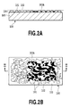
- Fig. 2A is a cross-sectional view illustrating a printed document in which an image is printed on the pressure-sensitive adhesive sheet of Fig. 1A ;
- Fig. 2B is a top view illustrating the printed document
- Fig. 3A to Fig. 3D are cross-sectional views illustrating steps of printing an image on the pressure-sensitive adhesive sheet of Fig. 1A , respectively;
- Fig. 4A to Fig. 4D are top views illustrating steps of printing the image on the pressure-sensitive adhesive sheet of Fig. 1A , respectively;
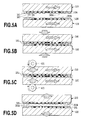
- Fig. 5A to Fig. 5D are cross-sectional views illustrating a step of adhering the pressure-sensitive adhesive sheets of Fig. 1A to each other and a peeling step;
- Fig. 6 is a cross-sectional view illustrating another configuration example of a printed document in which an image is printed on a pressure-sensitive adhesive sheet;
- Fig. 7 is a cross-sectional view illustrating still another configuration example of a printed document in which an image is printed on the pressure-sensitive adhesive sheet;
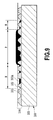
- Fig. 8 is a cross-sectional view illustrating still another configuration example of a printed document in which an image is printed on the pressure-sensitive adhesive sheet;
- Fig. 9 is a cross-sectional view illustrating still another configuration example of a printed document in which an image is printed on the pressure-sensitive adhesive sheet;
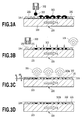
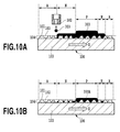
- Fig. 10A and Fig. 10B are cross-sectional views illustrating steps of preparing the printed document of Fig. 9 , respectively;
- Fig. 11A and Fig. 11B are top views illustrating the steps of preparing the printed document of Fig. 9 , respectively;
- Fig. 12 is a schematic side view illustrating the configuration example of the printing apparatus of the present invention.
- Fig. 13 is a perspective view illustrating the main part of the printing apparatus of Fig. 12 ;
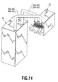
- Fig. 14 is a perspective view illustrating a print module installed in the printing apparatus of Fig. 12 ;
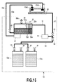
- Fig. 15 illustrates an ink flow path in the print module of Fig. 14 ;
- Fig. 16 is a block diagram illustrating a control system of the printing apparatus of Fig. 12 .
- Fig. 1A and Fig. 1B are schematic views illustrating the configuration example of a pressure-sensitive adhesive sheet 100 of the present invention.
- Fig. 1A is a cross-sectional view illustrating the pressure-sensitive adhesive sheet 100.
- Fig. 1B is a top view illustrating the pressure-sensitive adhesive sheet 100.
- Fig. 1A is a cross-sectional view taken along the line I-I of Fig. 1B .
- the pressure-sensitive adhesive sheet 100 of this example is structured so that a base member 103 has thereon a layer 104 of pressure-sensitive adhesive agent (the pressure-sensitive adhesive layer) and the pressure-sensitive adhesive layer 104 includes convex sections 101 and concave sections 102.
- the pressure-sensitive adhesive layer 104 is formed by applying pressure-sensitive adhesive agent onto the base member 103 by coating for example.
- the convex sections 101 are formed so as to have a close contact with the base member 103 and are independently sprinkled or are partially connected to one another.
- the convex sections 101 are partially connected to one another on the base member 103.
- the concave sections 102 are continuous to draw a groove-like pattern between the convex sections 101 or are individually divided.
- the pressure-sensitive adhesive layers 104 are not adhered to each other.
- the pressure-sensitive adhesive layers 104 are adhered to each other in a peelable manner.
- the pressure-sensitive adhesive layer 104 is not limited to a particular type so long as the pressure-sensitive adhesive layer 104 can achieve the function as described above.
- the pressure-sensitive adhesive sheet of this example is structured so that one face of the base member 103 has thereon the pressure-sensitive adhesive layer 104.
- a pattern forming method to form the convex sections 101 at the surface of the pressure-sensitive adhesive layer 104 is not limited to the particular one.
- a method can be used in which the pressure-sensitive adhesive layer 104 is formed on the base member 103 to subsequently use an embossed roll or the like to perform the pattern forming processing.
- the surface of the pressure-sensitive adhesive layer 104 subjected to the pattern forming processing preferably has a ten point average roughness (Rz) of 30 ⁇ m to 100 ⁇ m measured by a sensing pin-type surface roughness measuring instrument specified by JIS-B-0651 at a cutoff value of 0.8 mm specified by JIS-B-0601.
- Rz ten point average roughness
- a value of Rz lower than 30 ⁇ m may cause a printed image to be fixed to the surface of the pressure-sensitive adhesive layer 104, which tends to cause the ink offset.
- a value of Rz exceeding 100 ⁇ m causes ink ton sink in the concave section 102 formed among the plurality of convex sections 101, which tends to cause uneven density or white spot in the printed image.
- the surface of the pressure-sensitive adhesive layer 104 preferably has the ten point average roughness (Rz) in a range from 30 ⁇ m to 100 ⁇ m at the cutoff value of 0.8 mm. Furthermore, a ratio Rz' /Rz between Rz and the ten point average roughness (Rz') after the image printing stage is preferably in a range from 0.3 to 0.9.
- the percentage of the area of the convex section 101 to the total area of the pressure-sensitive adhesive layer 104 is preferably in a range from 30% to 80%.
- the percentage smaller than 30% causes a deteriorated adhesion force to cause a risk where the adhered pressure-sensitive adhesive layers peel from each other easily.
- the percentage exceeding 80% causes an excessively-strong adhesion force to cause a broken base member when the adhered pressure-sensitive adhesive layers are peeled to cause a risk of damage in printed information.
- the area of the convex section 101 means the area of the uppermost face of the convex section 101 when the surface of the pressure-sensitive adhesive layer 104 is seen from the top in the vertical direction.
- the pressure-sensitive adhesive layer of the pressure-sensitive adhesive sheet preferably has a contact angle to water of 90 degrees or less.
- the contact angle less than 90 degrees causes an insufficient amount of ink sunk in the concave section, which tends to cause the ink offset when the pressure-sensitive adhesive layers are compressed and peeled.
- the contact angle is an angle at an intersecting point of the surface of aqueous droplets placed on the pressure-sensitive adhesive layer and the pressure-sensitive adhesive layer that is formed by the tangent line to aqueous droplets and the pressure-sensitive adhesive layer.
- the value of the contact angle in the present invention is obtained by a measurement method as described below. Specifically, a pressure-sensitive adhesive paper including the pressure-sensitive adhesive layer was left in an environment of 23 degrees C and 50%RH for 12 hours to subsequently drip purified water on the pressure-sensitive adhesive layer. Then, in a range within which the fluid volume does not change (a range within which liquid droplets are not absorbed by the pressure-sensitive adhesive layer and are not evaporated), the contact angle when the spread of liquid droplets was maximum (after the 0.1 to 60 seconds after the dripping) was measured by a contact angle measurement tool. This measurement was carried out by an automatic contact angle measurement tool CA-VP (made by Kyowa Interface Science Co., Ltd.).
- the base member 103 used for the pressure-sensitive adhesive sheet 100 is not limited to the particular one.
- the base member 103 may be a noncoated paper such as a high-quality paper, a medium quality paper, a rough paper, a cotton paper, a coated paper such as an art paper, a coated paper, a light-weight coated paper, a resin-coated paper, cloth, a plastic laminate cloth, a plastic film, or a metal foil.
- the base member generally may have a basis weight of about 56 to 160g/m 2 .
- the surfaces of the base member are preferably subjected to an easy-adhesion processing by corona discharge for example.
- the coating thickness of the pressure-sensitive adhesive layer on the surface of the base after a drying step is not limited to the particular one.
- the coating thickness is preferably in a range from 1 ⁇ m to 20 ⁇ m in order to allow the pressure-sensitive adhesive layer to maintain the adhesiveness, peel property, or transparency or the like.
- the adhesive agent mainly included in the composition of the pressure-sensitive adhesive layer 104 is not limited to the particular one so long as the adhesive agent is not adherent in a normal status and is adherent when being pressurized.
- the adhesive agent may be any adhesive agent that can be selected from among substances used for substances generally used for the composition of the pressure-sensitive adhesive layer (e.g., natural rubber, synthetic rubber).
- natural rubber latex obtained by the graft copolymerization of natural rubber with styrene methyl methacrylate is preferred in view of the blocking resistance, heat resistance, abrasion resistance or the like.
- the pressure-sensitive adhesive layer 104 also can be appropriately blended with other additive agents (e.g., dispersant, thickener, flow modifier, antifoam agent, foam control agent, release agent, foaming agent, penetrating agent, fluorescent brightening agent, ultraviolet absorber, antioxidizing agent, antiseptic agent, antifungal agent, water resistant additive, wet strength agent, dry paper force enhancing agent, antistatic agent, age inhibitor).
- additive agents e.g., dispersant, thickener, flow modifier, antifoam agent, foam control agent, release agent, foaming agent, penetrating agent, fluorescent brightening agent, ultraviolet absorber, antioxidizing agent, antiseptic agent, antifungal agent, water resistant additive, wet strength agent, dry paper force enhancing agent, antistatic agent, age inhibitor.
- the composition of the pressure-sensitive adhesive layer 104 can be coated on the base member 103 by the same method as a conventional method to coat the pressure-sensitive adhesive agent on the pressure-sensitive adhesive sheet.
- the dry coating amount of the pressure-sensitive adhesive layer is generally in a range from 3 to 30g/m 2 , preferably 3 to 20g/m 2 , and more preferably 3 to 15g/m 2 .
- the dry coating amount of the pressure-sensitive adhesive layer lower than 3g/m 2 tends to cause an insufficient adhesion force.
- the dry coating amount of the pressure-sensitive adhesive layer exceeding 30g/m 2 may cause a risk where an excessively-strong adhesion force breaks the base member during the peeling to break the printed information.
- Fig. 2A is a cross-sectional view illustrating the active energy ray-curable aqueous ink that is applied to the pressure-sensitive adhesive sheet 100 and is cured.
- Fig. 2B is a top view illustrating the pressure-sensitive adhesive sheet 100.
- Fig. 2A is a cross-sectional view taken along the line II-II of Fig. 2B .
- the active energy ray-curable aqueous ink is ejected as described later through the inkjet printing head onto the pressure-sensitive adhesive layer 104. Thereafter, the active energy line-curable aqueous ink permeates the concave sections 102 among the plurality of the convex sections 101. As a result, the convex section 101 is exposed without being covered by color material 303A of aqueous ink.
- Ink used in this example is composed of color material, photopolymerization initiator, active energy ray-curable monomer, oligomer, polymer, and the mixture thereof.
- ink in this example also may be added with ion-exchange water, organic solvent, surface acting agent or the like in order to obtain an inkjet adequacy.
- nonabsorbable printing medium not absorbing ink e.g. , plastic, metal
- ultraviolet ray-curable monomer or oligomer can be used as solvent to provide a printed document that causes no burden on an environment and that has a superior adhesiveness.
- the active energy ray-curable monomer, oligomer, and polymer are preferably a compound having an ethylene unsaturated bond that can be subjected to a radical polymerization and may be any compound so long as the compound has in molecules one or more ethylene unsaturated bonds that can be subjected to a radical polymerization.
- the compound must be selected in consideration of the compatibility to pigment dispersant or solvent.
- two or more compounds also can be combined with a predetermined ratio in order to obtain the inkjet adequacy and the robustness of a printed document.
- a compound having an ethylene unsaturated bond that can radically polymerized may be, for example, unsaturated carboxylic acid(e.g., acrylic acid, methacrylic acid, itaconic acid, crotonic acid, isocrotonic acid, maleic acid) and the salt thereof, ester, urethane, amide, anhydride, acrylonitrile, and styrene.
- unsaturated carboxylic acid e.g., acrylic acid, methacrylic acid, itaconic acid, crotonic acid, isocrotonic acid, maleic acid
- Various radical polymerizable compounds such as unsaturated polyester, unsaturated polyether, unsaturated polyamide, or unsaturated urethane can be used.
- monofunctional acrylate may be: methyl acrylate, ethyl acrylate, butyl acrylate, dodecyl acrylate, 2-ethylhexyl acrylate, 2-hydroxyethyl acrylate, butoxyethyl acrylate, carbitol acrylate, cyclohexyl acrylate, tetrahydrofurfuryl acrylate, benzyl acrylate, diethylaminoethyl acrylate, dimethylaminoethyl acrylate, phenoxyethyl acrylate, glycidylethyl acrylate, methyl methacrylate, n-butyl methacrylate, 2-ethylhexyl methacrylate, lauryl methacrylate, allyl methacrylate, glycidyl methacrylate, benzyl methacrylate, dimethylaminomethyl methacrylate or the like.
- those having two or more functional groups may be: 1,4 butylene glycol diacrylate, 1,3 butylene glycol diacrylate, neopentyl glycol diacrylate, 1,6-hexanediol diacrylate, ethylene glycol diacrylate, diethylene glycol diacrylate, triethylene glycol diacrylate, tetraethylene glycol diacrylate, polyethylene glycol diacrylate, polypropylene glycol diacrylate, pentaerythritol triacrylate, pentaerythritol tetraacrylate, dipentaerythritol tetraacrylate, trimethylolpropane triacrylate, tetramethylolmethane tetraacrylate or the like.
- oligoester acrylate, N-methylol acrylamide, diacetone acrylamide, epoxy acrylate or the like also may be used. These substances are included in the printing fluid in a range from 5 weight% to 90 weight%.
- Photopolymerization initiator can be the known one used to cure ultraviolet cure monomer, oligomer, and polymer. Photopolymerization initiator is preferably the molecule cleaved one or the hydrogen abstraction-one. Specifically, photoinitiator may be: benzoin isobutyl ether, 2,4-diethyl thioxanthone, 2-isopropyl thioxanthone, benzyl, 2,4,6-trimethylbenzoyl diphenyl phosphine oxide, 2-benzyl-2-dimethyl amino-1-(4-morpholinophenyl)-butane-1-on, bis(2,6-dimethoxybenzoyl)-2,4,4-trimethylpentyl phosphine oxide, 1-hydroxycyclohexyl phenyl ketone, benzoin ethyl ether, benzyl dimethyl ketal, 2-hydroxy-2-methyl-1-phenylpropane-1-on, 1-(4-iso
- Color material used for ink can be any of dye and pigment. From the viewpoints of the stability to the irradiation of active energy line and the reliability of a printed document, pigment is more preferred. When dye is used, metal-containing dye having a strong light resistance is preferred. Ink (printing fluid) used in the present invention preferably includes color material having a weight ratio in a range from 1 to 20% (preferably in a range from 2 to 12%).
- Carbon black used for black ink may be the one by the Furness method, the one by the channel method, or the one obtained by subjecting high-specific surface area carbon (carbon black material) manufactured by activating petroleum coke by a great amount of alkali to a fluorine processing from a gas phase, a plasma processing of hydrophilic polymerizable monomer, a graft polymerization of hydrophilic monomer from liquid phase or the like.
- the carbon black as described above has the first particle diameter form 15 to 40 ⁇ m, a specific surface area by the BET method from 50 to 3000 square m/g, a DBP oil absorption amount from 40 to 150ml/100g, a volatile matter content from 0.5 to 10%, and a pH value from 2 to 9.
- a yellow pigment may be pigment yellow 1, 2, 3, 12, pigment yellow 13, pigment yellow 14, pigment yellow 16, pigment yellow 17, pigment yellow 55, pigment yellow 73, pigment yellow 74, pigment yellow 75, pigment yellow 83, pigment yellow 93, pigment yellow 95, pigment yellow 97, pigment yellow 98, pigment yellow 109, pigment yellow 110, pigment yellow 114, pigment yellow 128, pigment yellow 138, pigment yellow 139, pigment yellow 150, pigment yellow 151, pigment yellow 154, pigment yellow 180 or the like.
- Magenta pigment may be pigment red 5, pigment red 7, pigment 12, pigment 48 (Ca), pigment red 48(Mn), pigment red 57:1, pigment red 57(Sr), pigment red 57:2, pigment red 122, pigment red 123, pigment red 168, pigment 184, pigment red 202, pigment red 238 or the like.
- Cyan pigment may be pigment blue 1, pigment blue 2, pigment blue 3, pigment blue 16, pigment blue 22, pigment blue 60, pigment blue 15:2, pigment 15:3, bat blue 1, bat blue 60 or the like.
- the pigment as described above is dispersed by polymer resin and is used for printing fluid.
- Polymer resin is selected that has a superior compatibility with used solvent, monomer, oligomer, and polymer.
- the printing fluid can include a component such as ion-exchange water, glycol-base solvent, pyrrolidone-base solvent, lower alcohol-base solvent, glycol ether-base solvent, glycerin, glycerin derivative, urea, ethylene urea, urea derivative or the like.
- ink printing fluid
- aromatic hydrocarbons aliphatic hydrocarbons
- Pigment dispersing resin may be acrylic resin (e.g., acrylic acid ester resin, methacrylic acid ester resin, polyacrylic acid ester resin, ethylene-ethyl acrylate copolymer), olefin resin, phenolic resin, xylene resin, polyamide resin, polyester resin, ketone resin, alkyd resin, rosin resin, petroleum resin, ethylene-vinyl acetate copolymer resin, vinyl acetate resin, vinyl chloride-vinyl acetate copolymer resin, ethylene-vinyl chloride-vinyl acetate copolymer resin, ethyleneimine-hydroxy stearic acid copolymer or the like.
- acrylic resin e.g., acrylic acid ester resin, methacrylic acid ester resin, polyacrylic acid ester resin, ethylene-ethyl acrylate copolymer
- olefin resin e.g., phenolic resin, xylene resin, polyamide resin, polyester resin,
- the ink used in the present invention can be added with surfactant, antiseptic agent, antioxidizing agent, and other subsidiary materials for adjusting the property.
- the surfactant may be nonionic surfactant, amphoteric surfactant, cationic surfactant or the like. These surfactant are added for the purpose of achieving the permeability of printing fluid to a printing medium such as a paper, the wettability to a constituting member of the inkjet printing head, the flow property, or auxiliary substance to the dispersion stability or the like.
- the ink (printing fluid) used in the present invention is preferably used after cleaning and purifying color material in order to remove impurities.
- a constituting component adapted to a used inkjet method may be mixed in the printing fluid to subsequently subject the mixture to filtering and centrifugal separation or the like to remove impurities to obtain the printing fluid used in the present invention.
- Water is preferably added to aqueous ink with an additive amount in a range from 50 weight% to 80 weight% and more preferably in a range from 60 weight% to 70 weight%.
- the addition in a range lower than 50 weight% causes a higher viscosity to cause not only a deteriorated ink ejecting performance but also an ink surface tension to tend to cause a defective fixing and the ink offset.
- the addition in a range exceeding 80 weight% may cause a problem of a slower curing speed for example.
- the ink viscosity preferably does not have nonlinearity in a wide range and is lower than 15mPa ⁇ s. More preferably, the ink viscosity is lower than 5 to 10mPa ⁇ s. The ink viscosity exceeding 15mPa ⁇ s tends to cause ink to be adhered to the nozzle to cause the clogged nozzle.
- the ink surface tension is preferably from 20mN/m to 50mN/m.
- the surface tension lower than 20mN/m may cause ink to permeate the pressure-sensitive adhesive layer to cause a deteriorated reflection image density to fail to prevent the formation of a high-definition image required for a bar code printing.
- the surface tension exceeding 50mN/m can allow ink droplets to be effectively cured at the surface of a printing medium to sufficiently suppress the bleed and to obtain a high image density.
- an active energy irradiation (which will be described later) requires a printing medium to be wetted by ink droplets to a certain level.
- the upper limit of the surface tension is more preferably about 50m N/m.
- the surface tension here means a static surface tension that is measured by using an automatic surface tensiometer CBVP-Z (made by Kyowa Interface Science Co. , Ltd.) to use a platinum plate to measure the surface tension at 25 degrees C.
- the pressure-sensitive adhesive sheet of the present invention was caused to absorb water to use a dynamic permeability tester for measuring the fluid absorption by ultrasound to measure the time during which the maximum ultrasonic permeates the sheet. It was found that the time during which the maximum ultrasonic permeates the sheet is preferably 1 second or more to cause the maximum ultrasonic permeation rate 80% or more.
- the spread of ink dots formed by an inkjet printing method (which will be described later) is increased.
- the printed image has a lower reflection density to cause a risk to deteriorate fine printing small characters and the accuracy at which bar codes are read.
- the active energy ray-curable aqueous ink is ejected to the pressure-sensitive adhesive sheet as described later.
- Fig. 3A to Fig. 3D and Fig. 4A to Fig. 4D illustrate steps of using the inkjet printing head to eject the ultraviolet ray-curable cure aqueous ink as the active energy ray-curable aqueous ink (hereinafter also referred to as "UV ink") 303 onto the pressure-sensitive adhesive sheet 100 to fix the ink.
- UV ink active energy ray-curable aqueous ink
- the pressure-sensitive adhesive sheet 100 is transported in the direction shown by the arrow X.
- ink is ejected from the printing head 302.
- the UV ink 303 is ejected through a plurality of the nozzles of the printing head 302 to apply the UV ink 303 to the pressure-sensitive adhesive sheet 100.
- the ink 303 applied to the pressure-sensitive adhesive sheet 100 lands on the island-like convex section 101 and the groove-like concave section 102 in the pressure-sensitive adhesive layer 104 as shown in Fig. 3A and Fig. 4A .
- the ink 303 lands on the convex section 101 gradually permeates the concave section 102 through the capillary phenomenon and a part or the entirety thereof is stored in the concave section 102 as shown in Fig. 3B and Fig. 4B .
- the top of the convex section 101 is gradually exposed.
- Fig. 3B and Fig. 4B show the status where the permeation phenomenon of the ink 303 as described above is completed or the permeation still continues and the top of the convex section 101 is substantially exposed.
- the pressure-sensitive adhesive sheet 100 is transported in the direction shown by the arrow X and the printing region applied with the ink 303 is opposed to an ultraviolet irradiation lamp 306. Then, ultraviolet ray is emitted from the lamp 306 to the printing region.
- the ultraviolet ray causes ultraviolet ray curing agent (UV curing agent) included in the ink 303 to start a curing reaction.
- UV curing agent ultraviolet curing agent
- the ink 303 contained in the concave section 102 starts the curing while extruding water therein as shown in Fig. 3C and Fig. 4C .
- ultraviolet ray or a heat source causes moisture to be evaporated to cause the color material 303A to be fixed into the concave section 102.
- the ultraviolet ray cure aqueous ink is used as the ink 303 to allow the ink 303 to permeate the concave section 102 to subject ink to ultraviolet light while the convex section 101 is being exposed.
- the pressure-sensitive adhesive layer 104 includes ultraviolet ray curing agent (UV curing agent)
- UV curing agent ultraviolet curing agent
- the irradiation of ultraviolet ray causes the convex section 101 to start the curing reaction to subsequently shift to a status where a pressure-contacting step (which will be described later) is waited.
- the ink 303 may be applied to the pressure-sensitive adhesive sheet 100 in an amount not limited to a particular amount so long as the ink 303 is stored in the concave section 102.
- the applied amount of the ink 303 can be appropriately adjusted in accordance with the pressure-sensitive adhesive sheet 100.
- the applied amount of ink is excessive, a risk may be caused where ink covers the convex section of the pressure-sensitive adhesive layer to fail to provide the predetermined adhesion force (which will be described later).
- the ultraviolet irradiation lamp 306 is preferably a so-called low-pressure mercury lamp, a high-pressure mercury lamp, or a mercury lamp coated with fluorescent substance or the like that has a vapor pressure of mercury during lighting in a range from 1 to 10Pa.
- These mercury lamps have an emission spectrum in an ultraviolet ray region of 450nm or less (in particular, an emission spectrum in an ultraviolet ray region in a range from 184nm to 450nm in order to provide an effective reaction of polymerizable substances in a black color or a colored ink).
- the lamp 306 as described above can use a small power source and thus is suitable when the power source is provided in the printing apparatus.
- the mercury lamp may be, for example, a metal halide lamp, a high-pressure mercury lamp, an ultrahigh-pressure mercury lamp, a xenon flash tube, a deep UV lamp, a lamp using a microwave to excite a mercury lamp from outside in an electrodeless manner, or a UV laser or the like. Since these emission wavelength regions include the above range, various lamps as described above can be basically used so long as the power source size, an input intensity, the lamp shape or the like is permissible.
- the light source is also selected depending on the sensitivity of catalyst to be used.
- a required ultraviolet intensity is preferably in a range from about 1mW/cm 2 to 5,000mW/cm 2 in view of the relation with the ink polymerization speed.
- An insufficient irradiation intensity fails to provide sufficient curing of ink, causing a risk where the ink offset phenomenon may be caused.
- An excessive irradiation intensity may cause a damage in the base member of the pressure-sensitive adhesive sheet, the color degradation of color material of ink, or a deteriorated adhesion force of the pressure-sensitive adhesive layer.
- a plurality of ultraviolet lamps having UV wavelengths suitable for the adhesive agent and ink forming the pressure-sensitive adhesive layer also may be provided, respectively.
- ink When ink (printing fluid) includes water-soluble organic solvent, ink may be heated by a dryer, a microwave oscillation apparatus, or a far-infrared lamp or the like before ultraviolet irradiation to remove solvent left in the ink. As a result, the ink offset phenomenon can be reduced.
- a timing at which ink is heated is not limited to a particular timing so long as the timing is before the ultraviolet irradiation.
- the pressure-sensitive adhesive sheet also may be heated prior to the inkjet printing.
- the aqueous ink of this example includes at least moisture of 50% or more.
- the thickness H when ink is fixed on the pressure-sensitive adhesive sheet is 50% or lower of the thickness HO when ink is applied on the pressure-sensitive adhesive sheet.
- ink may partially cover the convex section 101 to cause a deteriorated adhesion force of the pressure-sensitive adhesive layer or to cause the ink offset.
- Ink applied to the pressure-sensitive adhesive layer preferably has a thickness reduced in a range from 10% to 70% when being cured.
- the ink 303 is applied on the pressure-sensitive adhesive sheet 100 to subsequently emit ultraviolet to the ink, thereby preparing a printed document.
- the following section will describe the adhesion and peeling between the pressure-sensitive adhesive sheets 100 as the printed document as described above.
- the two pressure-sensitive adhesive sheets 100 as a printed document are opposed to each other or the one pressure-sensitive adhesive sheet 100 is bent to oppose and abut the pressure-sensitive adhesive layers 104.
- the method to oppose and abut the pressure-sensitive adhesive layers 104 is not limited to a particular method.
- the pressure-sensitive adhesive sheet 100 also may be folded to provide two or three parts. Then, as shown in Fig. 5B , the pressure-sensitive adhesive layers 104 are caused to abut to each other. Then, a predetermined pressure is applied as shown in Fig. 5C to adhere the pressure-sensitive adhesive layers 104 to each other.
- a pressurization roller 401 is used to apply a pressure to the pressure-sensitive adhesive sheets 100 while transporting the pressure-sensitive adhesive sheets 100 in the direction shown by the arrow Y in Fig. 5C .
- the pressurization roller 401 preferably provides a pressurization force in a range from about 1kg/cm 2 to 10kg/cm 2 .
- the color material 303A of the ink is fixed in the concave section 102 and the convex section 101 is exposed without being covered by the color material 303A.
- the pressure-sensitive adhesive layers 104 are adhered to each other by allowing the respective convex sections 101 to be abutted to each other. Since the color material 303A is fixed in the concave section 102, the color material 303A is not positioned on the adhesion surfaces of the pressure-sensitive adhesive layers 104.
- the color material 303A in the concave section 102 is surrounded by the convex section 101 and is prevented from having a contact with the other pressure-sensitive adhesive layer 104. This can prevent the occurrence of the ink offset as will be described later.
- UV-curing agent ultraviolet curing agent
- ultraviolet light also may be emitted to increase the adhesion force of the convex sections 101 to be adhered to one another or the convex sections 101 also may be partially welded to adhere the pressure-sensitive adhesive layers 104 in a more secure manner.
- Fig. 5D is a schematic cross-sectional view when the interface of the information-supporting sheet as described above is peeled.
- a phenomenon can be suppressed from occurring in which the color material 303A at one of the pressure-sensitive adhesive layers is transferred to the convex section 101 at the other pressure-sensitive adhesive layer (i.e., ink offset phenomenon).
- the convex sections 101 of the respective pressure-sensitive adhesive layers adhered without being covered by the color material 303 can suppress the ink offset phenomenon from occurring without causing a deteriorated adhesion force.
- the following section will describe another example of the printed document obtained by applying the ink 303 on the pressure-sensitive adhesive sheet 100 to subsequently emit ultraviolet light thereto.
- the ink 501 that is the same as or different from the above-described ink 303 is used to print various information and images on parts other than the pressure-sensitive adhesive layer 104 of the pressure-sensitive adhesive sheet 100.
- the printed document of this example can be used for a postcard or the like.
- the pressure-sensitive adhesive layer 104 can be opposed and abutted to another pressure-sensitive adhesive layer to support individual information or the like and to use the ink 304 to print information for an address or the like.
- one surface of the pressure-sensitive adhesive sheet 100 includes a region in which the pressure-sensitive adhesive layer 104 is formed and a region in which the pressure-sensitive adhesive layer 104 is not formed, the latter region also may be subjected to a printing operation by the ink 501.
- the printed document shown in Fig. 7 is structured so that various information and images is printed (pre-printed) by the ink 502 on the base member 103 on which the pressure-sensitive adhesive layer 104 is not yet formed.
- the pre-printing may use a method such as the offset printing or a gravure printing or the like.
- the inkjet printing method also may be used to preferably use the above-described ink 303 as the ink 502.
- the printed contents by the ink 502 can be visually recognized through the transparent or translucent pressure-sensitive adhesive layer 104.
- the information and image printed by the ink 502 and the information and image printed by the ink 303 also can be partially superposed or dislocated from each other.
- the printed document shown in Fig. 8 is structured so that the ink 503 is used to form a covering layer over the base member 103 on which the pressure-sensitive adhesive layer 104 is not yet formed.
- This covering layer can be formed by the offset printing or the gravure printing or the like.
- This covering layer also can be formed by the inkjet printing method by the above-described ink 303 as the ink 503.
- the ink 503 forming this covering layer can be visually recognized through the transparent or translucent pressure-sensitive adhesive layer 104.
- the information and image printed by the ink 503 and the information and image printed by the ink 303 also can be partially superposed or dislocated from each other.
- the printed document shown in Fig. 9 is structured so that a great amount of the ink 303 is partially applied to the pressure-sensitive adhesive layer 104.
- the ink 303 cures while covering the convex section 101 of the pressure-sensitive adhesive layer 104 to cause a reduced adhesion force.
- the ink 303 cures without covering the convex section 101 of the pressure-sensitive adhesive layer 104 as described above, thus securing a sufficient adhesion force. In this manner, the adhesion force can be partially changed depending on the amount of applied ink 303.
- Fig. 10A, Fig. 10B , Fig. 11A, and Fig. 11B illustrate steps of manufacturing the printed document shown in Fig. 9 .
- Fig. 10A and Fig. 10B are a cross-sectional view taken along the X-X line in Fig. 11A and Fig. 11B , respectively.
- an appropriate amount of ink 303 enough to secure the sufficient adhesion force as in Fig. 3A as described above is applied to the region N on the pressure-sensitive adhesive layer 104.
- a great amount of the ink 303 is applied to the region P.
- the region A is a region to which the ink 303 is not applied.
- ultraviolet is emitted to cure the ink 303.
- the convex section 101 in the region N is exposed without being covered by the color material 303A of the ink 303 and the convex section 101 in the region P is covered by the color material 303A and is not exposed.
- the sufficient adhesion force is secured as in the region A with regard to the region N on the pressure-sensitive adhesive layer 104 and the adhesion force is weakened with regard to the region P.
- Fig. 12 is a schematic side view illustrating a configuration example of a printing apparatus to which the present invention can be applied.
- the printing apparatus of this example constitutes a line printer 10 in which a print module (print unit which will be described later) is installed.
- a printing head unit 20 and a transport unit 40 are provided.
- inkjet printing heads K1, K2, K3, K4, K5, and K6 are mounted for ejecting ink onto the pressure-sensitive adhesive sheet 100 to print an image.
- the transport unit 40 transports the pressure-sensitive adhesive sheet 100 in the direction shown by the arrow X. Black ink is ejected from all of the printing heads K1, K2, K3, K4, K5, and K6.
- the printing head unit 20 includes a head up-down motor 118 (see Fig. 16 ) or the like to move the respective printing heads K1 to K6 to a capping position, a printing position, and a wiping position (which will be described later).
- the printing head unit 20 is fixed to a plate-like engine base 30. The printing head unit 20 and the engine base 30 are moved in the up-and-down direction as will be described later.
- the engine base 30 fixed with the printing head unit 20 has a planar rectangle shape.
- the four corners are fixed with nuts 32.
- These nuts 32 are screwed to corresponding screw axes 34, respectively.
- the lower parts of these four screw axes 34 are fixed with sprockets 36.
- These four sprockets 36 have thereamong a hung chain 38.
- the chain 38 is rotated by a driving motor 41 to synchronously rotate the four screw axes 34 to move the printing head unit 20 in the up-and-down direction together with the nut 32 and the engine base 30.
- the transport unit 40 includes four transport belts 42 in order to transport the pressure-sensitive adhesive sheet 100 to the lower position of the printing head unit 20.
- the transport belt 42 is hung among driven rollers 44, 45, and 46, an encoder roller 47, and a driving roller 48 and is given with the tension by a tensioner 49.
- the driving roller 48 is rotated by the driving motor 41 via a timing belt 43 to cause the transport belt 42 to have a circling movement in the transportation direction shown by the arrow X.
- the line printer 10 includes an ink supply unit 50 to supply ink to the printing head unit 20.
- the ink supply unit 50 includes therein sub tanks 52a to 52f storing ink supplied to the respective printing heads K1 to K6.
- the ink supply unit 50 also includes therein ink tanks 53a to 53f (among which only the ink tank 53a is shown in Fig. 15 ) or the like to store ink supplied to the respective sub tanks 52a to 52f.
- the ink stored in the sub tank 52a is supplied to the printing head K1.
- the ink stored in the sub tank 52b is supplied to the printing head K2.
- inks are supplied from the sub tanks 52c to 52f to the printing heads K3 to K6, respectively.
- Through a tube 56 see Fig. 15 ), ink is supplied from the ink tank 53a to the sub tank 52a.
- inks are supplied from the ink tanks 53b to 53e through the tubes to the sub tanks 52b to 52e, respectively.
- the ink supply unit 50 and the printing head unit 20 have therebetween bundled ink supply tubes 60a to 60f and ink regression tubes 62a to 62f connected in a detachable manner.
- the ink supply tubes 60a to 60f form an ink supply path extending from the respective sub tanks 52a to 52f to the respective printing heads K1 to K6.
- the ink regression tubes 62a to 62f form an ink return flow path extending from the respective printing heads K1 to K6 to the respective sub tanks 52a to 52f.
- the printing head unit 20 includes a recovery unit 22 (see Fig. 15 ) in order to maintain the favorable status of ink ejected from the respective printing heads K1 to K6.
- Reference numeral 306 denotes the above-described ultraviolet irradiation lamp (UV lamp).
- the ultraviolet irradiation lamp is provided at a position at which ultraviolet light can be emitted to the pressure-sensitive adhesive sheet 100 applied with ink.
- Fig. 13 is a perspective view illustrating the main part of the printing head unit 20, the transport unit 40, and the ink supply unit 50.
- the printing head unit 20 is integrated with the ink supply unit 50 by the ink supply tubes 60a to 60f and the ink regression tubes 62a to 62f.
- This print module includes therein a control system of Fig. 16 .
- the respective printing heads K1 to K6 provided in the printing head unit 20 include a plurality of ejection openings through which ink can be ejected. These ejection openings are arranged in lines in a direction intersecting with the transportation direction shown by the arrow X (a direction orthogonal to the transportation direction in this example).
- the respective ejection opening lines have a length corresponding to the width of a printed image and are arranged along the transportation direction shown by the arrow X.
- black ink is ejected in an order of the respective printing heads K1 to K6 positioned at the upstream side in the transportation direction (i.e., in an order of the printing heads K6, K5, K4, K3, K2, and K1).
- the ink supply unit 50 is positioned to be away from the printing head unit 20 among which the ink supply tubes 60a to 60f and the ink regression tubes 62a to 62 are connected as described above (see Fig. 14 ).
- Fig. 15 illustrates ink flow paths in the printing head unit 20 and the ink supply unit 50.
- Fig. 15 typically shows the ink flow paths between the printing head K1 and the tanks (the sub tanks 52a and the ink tank 35a) corresponding to the printing head K1.
- the same structure applies to other ink flow paths of the printing heads K2 to K6.
- the ink tank 53a storing therein black ink is connected via an ink suction tube 56 to the sub tank 52a.
- a suction pump 58 is provided to suck the ink in the ink tank 53a to send ink into the sub tank 52a.
- valves 81 and 85 are closed and valves 82, 83, and 84 are opened to drive the suction pump 58 to suck ink in the ink tank 53a at the left side of Fig. 15 to send ink into the sub tank 52a.
- the two ink tanks 53a are provided so as to prevent ink shortage during a printing operation.
- valves 83, 84, 85, and 86 can be appropriately switched to connect the ink suction tube 56 to the other ink tank 53a.
- the valves 84 and 86 are an atmospheric pressure valve in order to introduce the atmospheric pressure into the ink tanks 53a.
- the interior of the sub tank 52a is connected to an air communication hole 88a.
- the valve 88 is opened to allow the interior of the sub tank 52a to communicate with outside air to provide the atmospheric pressure.
- the sub tank 52a is attached with an ink level sensor (fluid level detection sensor) 51 including electrodes 51a, 51b, and 51c in order to detect the existence of ink therein and the ink level. Based on a change in the resistance among these electrodes 51a, 51b, and 51c, the existence of ink is detected and the suction pump 58 and the valve are controlled so as to always provide a fixed ink level in the sub tank 52a.
- the sub tank 52a and the printing head K1 are positioned so that a difference in the ink hydraulic head is used to apply an optimal negative pressure to the ink ejection opening of the printing head K1.
- the sub tank 52a and the printing head K1 are connected with the ink supply tube 60a and the ink regression tube 62a so that ink can circulate between the sub tank 52a and the printing head K1.
- the sub tank 52a is connected to the ink supply tube 60a via an ink supply pump 59.
- the ink supply pump 59 is driven to pressurize the ink in the sub tank 52a to supply ink to the printing head K1.
- the valve 87 is opened to return ink in the printing head K1 to the sub tank 52a via the ink regression tube 62a.
- the recovery unit 22 is positioned. Ink supplied to the printing head K1 through pressurization is pushed out from the ejection opening by the closed valve 87 and is received by a cap of the recovery unit 22.
- the recovery unit 22 is connected to the sub tank 52a via an ink collection tube 57 and a part of an ink suction tube 56.
- the valve 82 is closed and the valve 81 is opened to drive the suction pump 58 so that the sub tank 52a collects the ink received in the cap of the recovery unit 22.
- the following section will describe an initial ink filling operation to fill ink, when the line printer 10 is newly provided, from the respective ink tank 53a or the like to the respective printing heads K1 to K6.
- the initial ink filling operation is carried out when the line printer 10 is in an initial startup status.
- the sub tank 52a, the ink suction tube 56, the ink supply tube 60a, the ink regression tube 62a, and the printing head K1 include therein no ink at all.
- an operation to fill ink in the sub tank 52a, the ink supply tube 60a, and the ink regression tube 62a or an operation to fill ink only in the sub tank 52a is carried out.
- the operation to fill ink in the sub tank 52a, the ink supply tube 60a, and the ink regression tube 62a causes, prior to the supply of ink from the sub tank 52a to the printing head K1, a not-connected status between the ink supply tube 60a and the printing head K1.
- the sub tank 52a and the ink supply tube 60a are filled with ink from a main tank 53a.
- the ink supply tube 60a is connected to the printing head K1 to supply the ink in the ink supply tube 60a to the printing head K1.
- An ejection opening face of the printing head K1 on which the ink ejection openings are formed is wiped by a cleaning blade (not shown) after the completion of the ink initial filling operation to wipe off the ink attached to the ejection opening face.
- one end 60at of the ink supply tube 60a is directly or indirectly connected to one end 62at of the ink regression tube 62a. Then, the ink supply pumps 58 and 59 are driven to circulate ink from the main tank 53a through the sub tank 52a, the ink supply tube 60a, and the ink regression tube 62a. This allows air existing in the ink supply tube 60a to be exchanged with ink to fill ink in the ink supply tube 60a.
- connection between the ink supply tube 60a and the ink regression tube 62a is cancelled to connect the ink supply tube 60a to the printing head K1 to supply ink in the ink supply tube 60a to the printing head K1.
- no air is introduced from the ink supply tube 60a into the printing head K1.
- the initial ink filling operation as described above also can be carried out by filling ink from the ink tank 53a only to the sub tank 52a. In this case, the valves 81 and 87 are closed and the valve 82 is opened to drive the suction pump 58.
- Fig. 16 is a block diagram illustrating the control system of the line printer 10. This control system is accommodated in the print module as described above.
- Printing data or a command sent from a host PC (host apparatus) 11 to a control system of Fig. 16 is received a CPU 101 via an interface controller 102.
- the CPU 101 is a computation processing apparatus that carries out the entire control in the line printer 10 such as the reception of the printing data and the printing operation or the like.
- the CPU 101 analyzes the received command to subject the image data of the respective color components of printing data to a bit map development in an image memory 106 to draw the image.
- the image memory 106 is used as an image development section.
- a capping motor 122 and a head up-down motor 118 are firstly driven via an input/output port 114 and a motor driving section 116 to move the respective printing heads K1 to K6 from the cap of the recovery unit 22 to move the respective printing heads K1 to K6 to the printing position (image formation position).
- a tip end detection sensor provided at a fixed position of the line printer 10 (not shown) is used to detect the tip end position of the pressure-sensitive adhesive sheet 100.
- the CPU 101 sequentially reads, based on an output signal from the encoder roller 47 (see Fig.
- the printing data of the corresponding color from the image memory 106 in synchronization with the transportation of the pressure-sensitive adhesive sheet 100. Then, the read printing data is transferred via a printing head control circuit 112 to the respective corresponding printing heads K1 to K6.
- the operation of the CPU 101 is carried out based on a processing program stored in the program ROM 104.
- the program ROM 104 stores therein a processing program corresponding to the control flow and a table or the like.
- a work RAM 108 is used as an operation memory.
- the CPU 101 drives the pump motor 124 via the input/output port 114 and the motor driving section 116.
- ink in the respective printing heads K1 to K6 can be pressurized to discharge ink through the ejection opening or to suck and discharge ink through the ejection opening to maintain the favorable ink ejection status of the respective printing heads K1 to K6.
- An image is printed on the pressure-sensitive adhesive sheet 100 based on a printing horizontal synchronization signal in synchronization with the transportation of the sheet. Then, the printing data of one image is divided and the divided pieces of data are allocated to the six printing heads K1 to K6, respectively so that the one image is printed through the cooperation by the six printing heads K1 to K6. Specifically, the printing data is divided to pieces of data in a raster direction (raster division) to allocate the pieces of data to the printing heads K1 to K6.
- the printing data corresponding to one raster allocated to the printing head K1 is sent from the image memory 106 from the printing head control circuit 112 in synchronization with a timing at which the position of the pressure-sensitive adhesive sheet 100 to be printed with the printing data is opposed to the printing head K1. Then, based on the printing data corresponding to the one raster, ink is ejected from the printing head K1. This also applies to other printing heads K2 to K6.
- the six printing heads K1 to K6 through which the same ink is ejected are provided.
- the printing data is allocated to the respective printing heads K1 to K6 for each raster or for a plurality of rasters.
- a plurality of printing heads that can eject different inks also can be provided as a printing head.
- the printing data can be subjected to the raster division as in the above-described case.
- potassium hydroxide solution neutralization rate of 110%, resin solid content of 15 parts
- styrene/acrylic acid/butyl acrylate copolymer acid number 150, weight average molecule amount 1100
- diethylene glycol diethylene glycol
- This solution was added with 15 parts of carbon black to subsequently use a sand mill to disperse the solution to prepare the aqueous dispersion element of carbon black.
- This aqueous dispersion element showed a solid content density of 14.5% and an average particle diameter of 110 nm.
- the average particle diameter was measured by a dynamic light scattering method (laser particle diameter analysis system PARIII, Otsuka Electronics, Co., Ltd.).
- the following section will describe specific examples of the composition of the aqueous ink prepared by the above aqueous dispersion element (Illustrative Embodiments 1 and 2 and Comparison Examples 1 and 2).
- the following section also will describe an image printing method, ultraviolet irradiation conditions, the evaluation result of the exposure level of the convex section of the pressure-sensitive adhesive layer, the evaluation result of the image curing, and the evaluation result of ink offset when these aqueous inks are used.
- compositions were mixed and were agitated for two hours. Then, the mixture was filtered by a 3 ⁇ m membrane filter to remove impurities to prepare ink.
- the ink was prepared in the same manner as in Illustrative Embodiment 1 except for that Acetylenol E100 of Illustrative Embodiment 1 was added with an additive amount of 3.0 parts.
- the ink was prepared in the same manner as in Illustrative Embodiment 1 except for that Acetylenol of Preparation Example 1 was deleted.
- the ink was prepared in the same manner as in Illustrative Embodiment 1 except for that ethylene glycol monobutyl ether of 5.0 parts and glycerin of 5.0 parts were added instead of the water-soluble the ultraviolet curing monomer, the water-soluble ultraviolet curing oligomer, and the photopolymerization initiator of Illustrative Embodiment 1.
- a printer BJ S600 marketed by Canon Inc. was used to use a pressure-sensitive adhesive printing sheet POSTEX (made by TOPPAN FORMS CO., LTD.) and the inks of the above Illustrative Embodiments 1 and 2 and Comparison Examples 1 and 2 to print a solid image with 100% duty. Thereafter, the images were irradiated with ultraviolet light based on the following conditions. Since the ink of Comparison Example 2 does not have an ultraviolet curing function, the printed image by the ink was not irradiated with ultraviolet light.
- Irradiation apparatus F300S (made by FUSION UV SYSTEMS)
- the inks of Illustrative Embodiments 1 and 2 and Comparison Examples 1 and 2 were used to print images based on the above printing method.
- the resultant images were visually evaluated for a timing before the ultraviolet irradiation based on the above irradiation conditions and a timing after the ultraviolet irradiation based on the above irradiation conditions.
- the evaluation before the ultraviolet irradiation was carried out based on three levels ( ⁇ , ⁇ , and ⁇ )
- the evaluation after the ultraviolet irradiation was carried out based on two levels ( ⁇ and ⁇ ).
- the printed image by the ink of Comparison Example 2 was not irradiated with ultraviolet light and was subjected to the same evaluation.
- the inks of Illustrative Embodiments 1 and 2 and Comparison Examples 1 and 2 were used to use the above printing method to print images.
- the images were irradiated with ultraviolet light under the above irradiation conditions.
- the images were touched by a finger to check the drying status of the images (tackiness, ink adherence to finger).
- the evaluation of the image curing as described above was carried out based on three levels ( ⁇ , ⁇ , and ⁇ ) as shown below.
- the printed image by the ink of Comparison Example 2 was subjected to the same evaluation without being irradiated with ultraviolet light.
- the evaluation result of the images are as shown in Table below.
- the pressure-sensitive adhesive layer of the pressure-sensitive adhesive sheet on which an image has been printed based on the above printing method and ultraviolet has been irradiated under the above irradiation conditions was opposed to and abutted to the pressure-sensitive adhesive layer of the pressure-sensitive adhesive sheet not printed with an image. Then, these sheets were compressed and peeled from each other. Then, the peeled sheets were visually evaluated with regard to the image transfer (ink offset).
- the evaluation of the ink offset as described above was carried out based on the three levels ( ⁇ , ⁇ , and ⁇ ).
- the evaluation result of the sheets is as shown in Table 2 below.
- the image printed by the ink of Comparison Example 2 was left and dried in a room (in RH at 25 degrees C) for 20 minutes or more after the image printing. However, the image printed by the ink of Comparison Example 2 was not yet dried and was still sticky and thus could not be evaluated with regard to the ink offset.
- the amount of the applied ink is specified. Specifically, the liquid ink is applied to the pressure-sensitive adhesive layer and is cured so that the convex section of the pressure-sensitive adhesive layer is exposed out of the cured ink, thereby printing an image.
- the present invention may apply liquid ink to cure the ink so that the convex section of the pressure-sensitive adhesive layer is exposed out of the cured ink.
- the ink type and the curing method may be selected appropriately.
- aqueous ink or oil-based ink can be used and energy line or heat other than ultraviolet or the like also can be used to cure ink.
- the ink application means is not limited to a configuration using the inkjet printing head and various ink application methods can be used.
- the inkjet printing head also can use various methods to eject ink using an electrical thermal converter (heater) or a piezo element or the like. When the electrical thermal converter is used, the generated heat can be used to foam ink to use the foaming energy to eject ink through the ink ejection opening.
- the image printing method also may be a so-called serial scan method to repeat printing operations by scanning the printing head in the main scanning direction and a transportation operation to transport the pressure-sensitive adhesive sheet as a printing medium in a direction intersecting with the main scanning direction.
- the present invention relates to a printing method, a printing apparatus, and a printed document by which an ink offset can be prevented while securing a sufficient adhesion force of the pressure-sensitive adhesive layer.
- Ink (303) is applied so that, when ink (303) applied to a pressure-sensitive adhesive layer (104) of a pressure-sensitive adhesive sheet (100) cures, a convex section (101) of the pressure-sensitive adhesive layer (104) exposed out of the curried ink, thereby printing an image.
Landscapes
- Physics & Mathematics (AREA)
- Health & Medical Sciences (AREA)
- Electromagnetism (AREA)
- General Health & Medical Sciences (AREA)
- Toxicology (AREA)
- Engineering & Computer Science (AREA)
- Mechanical Engineering (AREA)
- Plasma & Fusion (AREA)
- Ink Jet (AREA)
- Ink Jet Recording Methods And Recording Media Thereof (AREA)
- Inks, Pencil-Leads, Or Crayons (AREA)
Applications Claiming Priority (1)
| Application Number | Priority Date | Filing Date | Title |
|---|---|---|---|
| JP2007123583A JP4960143B2 (ja) | 2007-05-08 | 2007-05-08 | 記録方法、記録装置、および記録物 |
Publications (3)
| Publication Number | Publication Date |
|---|---|
| EP1990207A1 true EP1990207A1 (de) | 2008-11-12 |
| EP1990207B1 EP1990207B1 (de) | 2015-09-02 |
| EP1990207B8 EP1990207B8 (de) | 2016-01-27 |
Family
ID=39689106
Family Applications (1)
| Application Number | Title | Priority Date | Filing Date |
|---|---|---|---|
| EP08155783.7A Ceased EP1990207B8 (de) | 2007-05-08 | 2008-05-07 | Tintenstrahldruckverfahren und Vorrichtung |
Country Status (4)
| Country | Link |
|---|---|
| US (1) | US8246157B2 (de) |
| EP (1) | EP1990207B8 (de) |
| JP (1) | JP4960143B2 (de) |
| CN (1) | CN101342830B (de) |
Families Citing this family (9)
| Publication number | Priority date | Publication date | Assignee | Title |
|---|---|---|---|---|
| JP5114454B2 (ja) * | 2009-06-04 | 2013-01-09 | 株式会社ミマキエンジニアリング | インクおよびインクジェットプリンタ並びにプリント方法 |
| US9340693B2 (en) * | 2011-03-28 | 2016-05-17 | Konica Minolta, Inc. | Actinic ray curable inkjet ink and image recording method using same |
| JP6094054B2 (ja) * | 2012-05-01 | 2017-03-15 | セイコーエプソン株式会社 | 記録物の製造方法 |
| JP6094055B2 (ja) * | 2012-05-02 | 2017-03-15 | セイコーエプソン株式会社 | 記録物の製造方法 |
| JP6268947B2 (ja) * | 2013-11-06 | 2018-01-31 | セイコーエプソン株式会社 | 記録物の製造方法 |
| JP6268946B2 (ja) * | 2013-11-06 | 2018-01-31 | セイコーエプソン株式会社 | 記録物の製造方法 |
| JP2016175985A (ja) * | 2015-03-19 | 2016-10-06 | 富士ゼロックス株式会社 | インク、インクカートリッジ、記録装置、及び記録方法 |
| JP6374418B2 (ja) * | 2016-01-27 | 2018-08-15 | キヤノンファインテックニスカ株式会社 | 転写材、記録物、記録物の製造装置、および記録物の製造方法 |
| US10308057B2 (en) * | 2016-12-02 | 2019-06-04 | Canon Finetech Nisca Inc. | Transfer material, printed material, and manufacturing method for printed material |
Citations (7)
| Publication number | Priority date | Publication date | Assignee | Title |
|---|---|---|---|---|
| JPH0958118A (ja) | 1995-08-30 | 1997-03-04 | Mitsubishi Paper Mills Ltd | 感圧接着性記録シート |
| JPH1148651A (ja) | 1997-07-31 | 1999-02-23 | Toppan Forms Co Ltd | インクジェット記録用情報担持用シート |
| JPH11334201A (ja) | 1998-05-27 | 1999-12-07 | Daio Paper Corp | インクジェット記録用圧着紙 |
| JP2001262105A (ja) * | 2000-03-23 | 2001-09-26 | Toppan Forms Co Ltd | インクジェットインクの定着性に優れた感圧接着剤組成物およびそれを用いた情報担持用シート |
| JP2004090593A (ja) * | 2002-09-04 | 2004-03-25 | Hokuetsu Paper Mills Ltd | 再剥離性圧着記録用紙 |
| US20060203024A1 (en) * | 2005-03-10 | 2006-09-14 | Fuji Photo Film Co., Ltd. | Image forming apparatus and method |
| EP1712603A1 (de) * | 2000-04-24 | 2006-10-18 | Avery Dennison Corporation | Klebstoffartikel mit verbessertem Luftaustritt und Verfahren zu deren Herstellung |
Family Cites Families (6)
| Publication number | Priority date | Publication date | Assignee | Title |
|---|---|---|---|---|
| JPH0410082U (de) * | 1990-05-18 | 1992-01-28 | ||
| JP3677685B2 (ja) * | 1992-03-31 | 2005-08-03 | トッパン・フォームズ株式会社 | 情報担体用シート |
| JPH1148650A (ja) * | 1997-07-31 | 1999-02-23 | Toppan Forms Co Ltd | インクジェット記録用情報担持用シート |
| US6130024A (en) * | 1998-11-20 | 2000-10-10 | Eastman Kodak Company | Strippable repositionable back sheet for photographic element |
| JP3717439B2 (ja) * | 2001-10-01 | 2005-11-16 | 大王製紙株式会社 | 疑似接着用紙 |
| CN100429128C (zh) * | 2006-08-25 | 2008-10-29 | 广州咏顺包装材料有限公司 | 立体防伪拉线的制造方法 |
-
2007
- 2007-05-08 JP JP2007123583A patent/JP4960143B2/ja active Active
-
2008
- 2008-05-02 US US12/114,386 patent/US8246157B2/en not_active Expired - Fee Related
- 2008-05-07 EP EP08155783.7A patent/EP1990207B8/de not_active Ceased
- 2008-05-08 CN CN2008100818556A patent/CN101342830B/zh not_active Expired - Fee Related
Patent Citations (7)
| Publication number | Priority date | Publication date | Assignee | Title |
|---|---|---|---|---|
| JPH0958118A (ja) | 1995-08-30 | 1997-03-04 | Mitsubishi Paper Mills Ltd | 感圧接着性記録シート |
| JPH1148651A (ja) | 1997-07-31 | 1999-02-23 | Toppan Forms Co Ltd | インクジェット記録用情報担持用シート |
| JPH11334201A (ja) | 1998-05-27 | 1999-12-07 | Daio Paper Corp | インクジェット記録用圧着紙 |
| JP2001262105A (ja) * | 2000-03-23 | 2001-09-26 | Toppan Forms Co Ltd | インクジェットインクの定着性に優れた感圧接着剤組成物およびそれを用いた情報担持用シート |
| EP1712603A1 (de) * | 2000-04-24 | 2006-10-18 | Avery Dennison Corporation | Klebstoffartikel mit verbessertem Luftaustritt und Verfahren zu deren Herstellung |
| JP2004090593A (ja) * | 2002-09-04 | 2004-03-25 | Hokuetsu Paper Mills Ltd | 再剥離性圧着記録用紙 |
| US20060203024A1 (en) * | 2005-03-10 | 2006-09-14 | Fuji Photo Film Co., Ltd. | Image forming apparatus and method |
Also Published As
| Publication number | Publication date |
|---|---|
| CN101342830A (zh) | 2009-01-14 |
| EP1990207B8 (de) | 2016-01-27 |
| EP1990207B1 (de) | 2015-09-02 |
| CN101342830B (zh) | 2010-12-22 |
| JP4960143B2 (ja) | 2012-06-27 |
| US8246157B2 (en) | 2012-08-21 |
| JP2008279612A (ja) | 2008-11-20 |
| US20090033730A1 (en) | 2009-02-05 |
Similar Documents
| Publication | Publication Date | Title |
|---|---|---|
| EP1990207B1 (de) | Tintenstrahldruckverfahren und Vorrichtung | |
| US8118419B2 (en) | Ink jet recording method, recording device, ink/recording medium set, recording matter | |
| US7914108B2 (en) | Image forming apparatus and method, and ink set | |
| EP3524648B1 (de) | Transfer von uv-druck auf gekrümmte oberflächen mit dehnbaren uv-tinten | |
| CN104797665A (zh) | 光固化型喷墨印刷用油墨组合物以及印刷物 | |
| US20120156444A1 (en) | Transfer medium, production method thereof, and transferred matter | |
| JPWO2015151833A1 (ja) | 光硬化性組成物、及びそれを含有する光硬化性インクジェットインク、光硬化性組成物を用いた記録方法、並びに光硬化性インクジェットインクを用いた記録方法 | |
| JP2003191601A (ja) | インクジェット記録方法、インクジェット記録画像及びインクジェット記録画像における光沢感の差の緩和方法 | |
| JP2002225415A (ja) | インクジェット印刷方法、印刷装置、及びこの方法で形成された印刷物 | |
| CN100581819C (zh) | 改进的喷墨印刷系统 | |
| US20150210087A1 (en) | Ink jet recording method and recording apparatus | |
| JP5707752B2 (ja) | 液体吐出装置 | |
| JP2007245630A (ja) | インクジェット記録方法 | |
| JP4105422B2 (ja) | 記録装置 | |
| JP4540718B2 (ja) | 記録装置 | |
| CN102673136B (zh) | 印刷物及印刷物的制造方法 | |
| JP6518296B2 (ja) | 転写材、記録物、および記録物の製造方法 | |
| EP1574352B1 (de) | Tintenstrahlaufzeichnungsverfahren | |
| JP2013215994A (ja) | 印刷装置及び印刷方法 | |
| JP2009119872A (ja) | インクジェット画像形成方法 | |
| JP4760269B2 (ja) | インクジェット画像形成装置 | |
| US12459254B2 (en) | Printing apparatus and control method | |
| JP2007296808A (ja) | インクジェット記録方法、記録装置、該装置用インクセットおよび記録物 | |
| JP2006082378A (ja) | インクジェット記録方法および記録媒体 | |
| JP2011084025A (ja) | 印刷装置及び印刷方法 |
Legal Events
| Date | Code | Title | Description |
|---|---|---|---|
| PUAI | Public reference made under article 153(3) epc to a published international application that has entered the european phase |
Free format text: ORIGINAL CODE: 0009012 |
|
| AK | Designated contracting states |
Kind code of ref document: A1 Designated state(s): AT BE BG CH CY CZ DE DK EE ES FI FR GB GR HR HU IE IS IT LI LT LU LV MC MT NL NO PL PT RO SE SI SK TR |
|
| AX | Request for extension of the european patent |
Extension state: AL BA MK RS |
|
| 17P | Request for examination filed |
Effective date: 20090407 |
|
| 17Q | First examination report despatched |
Effective date: 20090528 |
|
| AKX | Designation fees paid |
Designated state(s): DE FR GB |
|
| REG | Reference to a national code |
Ref country code: DE Ref legal event code: R079 Ref document number: 602008039898 Country of ref document: DE Free format text: PREVIOUS MAIN CLASS: B41J0011000000 Ipc: B41M0005000000 |
|
| GRAP | Despatch of communication of intention to grant a patent |
Free format text: ORIGINAL CODE: EPIDOSNIGR1 |
|
| INTG | Intention to grant announced |
Effective date: 20130704 |
|
| RIC1 | Information provided on ipc code assigned before grant |
Ipc: B41M 5/00 20060101AFI20130624BHEP Ipc: B41J 11/00 20060101ALI20130624BHEP Ipc: B41M 7/00 20060101ALI20130624BHEP |
|
| GRAJ | Information related to disapproval of communication of intention to grant by the applicant or resumption of examination proceedings by the epo deleted |
Free format text: ORIGINAL CODE: EPIDOSDIGR1 |
|
| INTC | Intention to grant announced (deleted) | ||
| GRAP | Despatch of communication of intention to grant a patent |
Free format text: ORIGINAL CODE: EPIDOSNIGR1 |
|
| RAP1 | Party data changed (applicant data changed or rights of an application transferred) |
Owner name: CANON FINETECH INC. |
|
| INTG | Intention to grant announced |
Effective date: 20150323 |
|
| GRAS | Grant fee paid |
Free format text: ORIGINAL CODE: EPIDOSNIGR3 |
|
| GRAA | (expected) grant |
Free format text: ORIGINAL CODE: 0009210 |
|
| AK | Designated contracting states |
Kind code of ref document: B1 Designated state(s): DE FR GB |
|
| REG | Reference to a national code |
Ref country code: GB Ref legal event code: FG4D |
|
| REG | Reference to a national code |
Ref country code: DE Ref legal event code: R096 Ref document number: 602008039898 Country of ref document: DE |
|
| RIN2 | Information on inventor provided after grant (corrected) |
Inventor name: HAYASHI, KUNITOSHI Inventor name: OKUTSU, JIN Inventor name: HIRASAWA, AKIRA Inventor name: SHINO, YOSHIYUKE Inventor name: NONAKA, KUMIKO Inventor name: SUGA, YUKO |
|
| RIN2 | Information on inventor provided after grant (corrected) |
Inventor name: SHINO, YOSHIYUKE Inventor name: NONAKA, KUMIKO Inventor name: OKUTSU, JIN Inventor name: HIRASAWA, AKIRA Inventor name: HAYASHI, KUNITOSHI Inventor name: SUGA, YUKO |
|
| RIN2 | Information on inventor provided after grant (corrected) |
Inventor name: SUGA, YUKO Inventor name: HAYASHI, KUNITOSHI Inventor name: SHINO, YOSHIYUKI Inventor name: HIRASAWA, AKIRA Inventor name: OKUTSU, JIN Inventor name: NONAKA, KUMIKO |
|
| REG | Reference to a national code |
Ref country code: FR Ref legal event code: PLFP Year of fee payment: 9 |
|
| REG | Reference to a national code |
Ref country code: DE Ref legal event code: R097 Ref document number: 602008039898 Country of ref document: DE |
|
| PLBE | No opposition filed within time limit |
Free format text: ORIGINAL CODE: 0009261 |
|
| STAA | Information on the status of an ep patent application or granted ep patent |
Free format text: STATUS: NO OPPOSITION FILED WITHIN TIME LIMIT |
|
| 26N | No opposition filed |
Effective date: 20160603 |
|
| REG | Reference to a national code |
Ref country code: FR Ref legal event code: PLFP Year of fee payment: 10 |
|
| REG | Reference to a national code |
Ref country code: FR Ref legal event code: PLFP Year of fee payment: 11 |
|
| PGFP | Annual fee paid to national office [announced via postgrant information from national office to epo] |
Ref country code: DE Payment date: 20190423 Year of fee payment: 12 |
|
| PGFP | Annual fee paid to national office [announced via postgrant information from national office to epo] |
Ref country code: FR Payment date: 20190410 Year of fee payment: 12 |
|
| PGFP | Annual fee paid to national office [announced via postgrant information from national office to epo] |
Ref country code: GB Payment date: 20190501 Year of fee payment: 12 |
|
| REG | Reference to a national code |
Ref country code: DE Ref legal event code: R119 Ref document number: 602008039898 Country of ref document: DE |
|
| GBPC | Gb: european patent ceased through non-payment of renewal fee |
Effective date: 20200507 |
|
| PG25 | Lapsed in a contracting state [announced via postgrant information from national office to epo] |
Ref country code: FR Free format text: LAPSE BECAUSE OF NON-PAYMENT OF DUE FEES Effective date: 20200531 Ref country code: GB Free format text: LAPSE BECAUSE OF NON-PAYMENT OF DUE FEES Effective date: 20200507 |
|
| PG25 | Lapsed in a contracting state [announced via postgrant information from national office to epo] |
Ref country code: DE Free format text: LAPSE BECAUSE OF NON-PAYMENT OF DUE FEES Effective date: 20201201 |