EP1982948A2 - Tampon glissant pour flèche - Google Patents
Tampon glissant pour flèche Download PDFInfo
- Publication number
- EP1982948A2 EP1982948A2 EP08152244A EP08152244A EP1982948A2 EP 1982948 A2 EP1982948 A2 EP 1982948A2 EP 08152244 A EP08152244 A EP 08152244A EP 08152244 A EP08152244 A EP 08152244A EP 1982948 A2 EP1982948 A2 EP 1982948A2
- Authority
- EP
- European Patent Office
- Prior art keywords
- jib
- pad
- jib structure
- supporting member
- sliding
- Prior art date
- Legal status (The legal status is an assumption and is not a legal conclusion. Google has not performed a legal analysis and makes no representation as to the accuracy of the status listed.)
- Withdrawn
Links
Images


Classifications
-
- B—PERFORMING OPERATIONS; TRANSPORTING
- B66—HOISTING; LIFTING; HAULING
- B66C—CRANES; LOAD-ENGAGING ELEMENTS OR DEVICES FOR CRANES, CAPSTANS, WINCHES, OR TACKLES
- B66C23/00—Cranes comprising essentially a beam, boom, or triangular structure acting as a cantilever and mounted for translatory of swinging movements in vertical or horizontal planes or a combination of such movements, e.g. jib-cranes, derricks, tower cranes
- B66C23/62—Constructional features or details
- B66C23/64—Jibs
- B66C23/70—Jibs constructed of sections adapted to be assembled to form jibs or various lengths
- B66C23/701—Jibs constructed of sections adapted to be assembled to form jibs or various lengths telescopic
- B66C23/707—Jibs constructed of sections adapted to be assembled to form jibs or various lengths telescopic guiding devices for telescopic jibs
Definitions
- the present invention relates to an extendable and stowable jib of a working machine such as a crane. Particularly, the present invention relates to a structure of a sliding pad to be attached to the above jib.
- An example of a working machine to which the present invention is applied includes a crane and an elevating work vehicle.
- An extendable and stowable jib provided in the above working machine has a plurality of jib structures which are telescopically inserted into each other.
- a sliding pad is provided between an inner jib structure and an outer jib structure arranged on the outside of the inner jib structure. This kind of sliding pad is installed to an outer surface in the base end portion of the inner jib structure and an inner surface on the front end portion of the outer jib structure so as to stably support the jib structures when a base end portion of the inner jib structure is located anywhere inside the inner jib structure.
- an inner boom is extendably and stowably inserted into an outer boom in a square cylindrical shape, and to the both sides of a base end portion of the inner boom, side pads sliding on an inner surface of the outer boom are attached.
- the side pad is screwed into a side surface of the inner boom by a screw.
- a shearable pin stretching from the side pad to the inner boom is provided.
- a shim having a cutout portion in a U shape is disposed. In the side pad, by adjusting a thickness of the shim, it is possible to adjust a clearance between the side pad and the outer boom.
- a side pad disclosed in Japanese Utility Model Laid-Open No. Hei7-35484 .
- fitting holes are provided in the base end portions of the boom structures to be inserted, and the pads are fitted into the fitting holes in a state of protruding from surfaces of the booms.
- a stopper portion for resisting against suppress strength worked on the pad from the outside.
- the stopper portion an example in which the pad fitted into the fitting hole of the boom base end portion is fixed by a bolt from the inside of the boom is disclosed.
- the jib according to the present invention is an extendable and stowable jib comprises a plurality of jib structures which are telescopically inserted into each other.
- the jib according to the present invention is provided with an inner jib structure, an outer jib structure arranged on the outside of the inner jib structure, and a sliding pad arranged between the inner jib structure and the outer jib structure.
- the sliding pad is attached on the base end portion of the inner jib structure slidably on an inner surface of the outer jib structure.
- the first aspect of the present invention is that a supporting member protruding towards the inner surface of the outer jib structure is provided in the inner jib structure, and the sliding pad is connected to the supporting member so as to restrict movement in the perpendicular direction to the protruding direction of the supporting member.
- the sliding pad is attached in a state of being sandwiched by the outer jib structure and the supporting member in the protruding direction of the supporting member, and the movement of them in the protruding direction is restricted by the outer jib structure. In the perpendicular direction to the protruding direction, the movement is restricted by the supporting member. Thereby, it is possible to surely prevent the sliding pad from dropping off.
- the supporting member is installed in the jib structure so that the sliding pad can be attached to the jib structure through the supporting member. Therefore, there is no need for forming a hole which lowers the strength of the jib structure in the jib structure. Consequently, it is possible to prevent the lowering of the strength of the jib structure.
- the jib includes a main jib capable of raising and lowering mounted in an upper rotating body of a crane or the like, for example, and an auxiliary jib connected to a front end of the main jib. That is, there is a case where the main jib and constituent components thereof are called the "boom". In such a case, the auxiliary jib is sometimes simply called the "jib". However, the term "jib" in the present specification includes not only the main jib but also the auxiliary jib.
- the sliding pad has a pad head portion having a sliding surface sliding on the inner surface of the outer jib structure, and a pad body portion formed in a hollow shape and extending from an end on the opposite side of the sliding surface of the pad head portion.
- the pad body portion is connected to an end of the supporting member.
- a protruding length of the supporting member is adjustable from the inner jib structure.
- the supporting member is formed in an axial shape, and a male screw is threaded on at least a part of the axial portion of the supporting member.
- the supporting member is screwed into a screw hole formed in the inner jib structure.
- the supporting member by rotating the supporting member, the supporting member is inserted into or out of the screw hole so that the protruding length of the supporting member from the inner jib structure can be continuously adjusted.
- the clearance between the sliding surface of the sliding pad and the inner surface of the outer jib structure with a simple mechanism, and adjustment is also easily and precisely performed.
- the protruding length of the supporting member is adjustable from the inside of the inner jib structure.
- the supporting member is formed in an axial shape, and a male screw is threaded on at least a part of the axial portion of the supporting member.
- the supporting member is screwed into a screw hole formed in the inner jib structure in a state that an end of the supporting member protrudes towards the inside of the inner jib structure.
- An engaging portion is provided in the end and the supporting member can be rotated around an axis by the engaging portion.
- the end of the supporting member protrudes towards the inside of the jib, and the engaging portion is provided in the end. Therefore, it is possible to rotate the supporting member by engaging a tool or the like with the engaging portion. Thereby, since operation of rotating and moving the supporting member to the jib is easily performed, it is possible to efficiently adjust the clearance between the sliding surface of the sliding pad and the inner surface of the outer jib structure.
- the supporting member extends towards the inner surface of the outer jib structure and is formed in a hollow shape.
- the sliding pad is fitted into the inside of the supporting member so as to outwardly protrude one end serving as a sliding surface.
- the sliding pad by inserting the sliding pad into the supporting member, it is possible to mount the sliding pad to the jib structure. Therefore, the mounting operation is easily performed. Since the sliding pad is formed in a simple shape, forming the sliding pad is easily performed.
- a positioning member for supporting an end surface on the opposite side of the sliding surface in the sliding pad is provided therewith.
- a male screw is threaded on at least a part of the axial portion of the positioning member, and the positioning member is screwed into a screw hole formed in the inner jib structure.
- opening portions are formed on wall surfaces of a plurality of the jib structures constituting the jib.
- the opening portions are formed at a position where the outside of the jib are linearly communicated to the supporting member through the opening portions in a state that the jib is stowed.
- the mounting and positioning adjustment of the sliding pad are easily performed. Maintenance of the sliding pad or the like is also easily performed.
- the inner jib structure is provided with a bracket extending from an end surface of a base end portion of the inner jib structure in the stowing direction.
- the bracket has a pair of supporting walls extending opposing to each other in a clearance narrower than a width of the inner jib structure, and the supporting member is fixed to the supporting walls.
- a pair of the supporting walls are arranged in the clearance narrower than the width of the inner jib structure. Therefore, it is possible to widen the clearance between the supporting walls and the inner surface of the outer jib structure. In such a case, it is possible to further increase the length of the supporting member protruding from the supporting walls, and it is also possible to increase the length of the sliding pad to be fitted into the supporting member in the protruding direction. Therefore, it is possible to further increase the depth for fitting the sliding pad into the supporting member, and it is possible to surely fix the sliding pad by the supporting member.
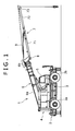
- Fig. 1 is an entire view showing a wheel crane provided with a sliding pad for a jib according to the first embodiment of the present invention.
- a wheel crane 1 is provided with a lower traveling body 2 having wheels 2a and 2b, and an upper rotating body 4 mounted on the lower traveling body 2 rotatably around a vertical shaft through a rotation bearing 3.
- a cab 5 serving as an operator cab at the time of traveling and a control cab at the time of performing a crane work.
- a main jib 6 extending towards the front side of the cab 5 and an auxiliary jib 7 connected to a front end portion of the main jib 6 in the extending direction.
- the main jib 6 is formed into a box structure, and it comprises a basic jib structure 6a and a plurality of movable jib structures 6b which are telescopically, extendably and stowably inserted into each other.
- a base end portion of the most outer basic jib structure 6a is pivoted by a jib foot pin (not shown) on the upper rotating body 4. It is possible to raise and lower the main jib 6.
- the jib foot pin functions as a supporting point.
- the auxiliary jib 7 is also formed into a box structure, and it comprises a first jib structure 71, a second jib structure 72 and a third jib structure 73 which are telescopically and extendably inserted into each other. It should be noted that Fig. 1 shows an intermediate projecting state in which the second jib structure 72 housing the third jib structure 73 extends forward from the first jib structure 71.
- a base end portion of the first jib structure 71 located at the most outer part of the auxiliary jib 7 is axially supported by a supporting axis 8 located on the lower side of the front end portion of the main jib 6.
- a front end portion of the first jib structure 71 and the front end portion of the main jib 6 are coupled with each other through a jib suspension rod 9 serving as a coupling member in a rod shape.
- both ends of the first jib structure 71 of the auxiliary jib 7 are coupled with the main jib 6 and the auxiliary jib 7 is raised and lowered in accordance with raising and lowering of the main jib 6.
- the sliding pad for a jib according to the embodiment of the present invention is applicable to the main jib 6 and the auxiliary jib 7 serving as working attachment of the wheel crane 1 mentioned above.
- the case where the sliding pad according to the present invention is applied to the auxiliary jib 7 will be mentioned as an example.
- the sliding pad according to the present embodiment is applied to a sliding pad 10 disposed between the second jib structure 72 and the third jib structure 73 of the auxiliary jib 7.
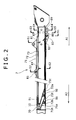
- Fig. 2 is a partially sectional view showing the auxiliary jib 7 in Fig. 1 , and a view schematically showing a state that the auxiliary jib 7 is completely stowed. That is, the second jib structure 72 and the third jib structure 73 are drawn to the side of the first jib structure 71.
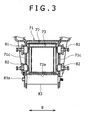
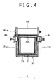
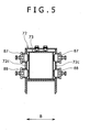
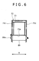
- Figs. 3 to 6 are sectional arrow views by lines S1-S1, S2-S2, S3-S3 and S4-S4 respectively in Fig. 2 .
- the first jib structure 71, the second jib structure 72 and the third jib structure 73 are telescopically fitted in order from outside.
- vertical cross sections of the jib structures 71 to 73 in the longitudinal direction are substantially formed into rectangular shape.
- the first jib structure 71 is a square cylindrical jib structure located on the outermost side in the auxiliary jib 7.
- the second jib structure 72 can slide along an inner surface of a peripheral wall of the first jib structure 71.
- the second jib structure 72 is a square cylindrical jib structure located adjacent to and inside the first jib structure 71.
- the second jib structure 72 is movable in the extending direction of the jib structure or in the stowing direction which is the opposite direction to the extending direction in a state that movement thereof in the width direction is restricted within a predetermined range by sliding pads 81 and 82 installed on side walls 71c of the first jib structure 71.
- the width direction indicates a direction shown by an arrow B in Figs. 3 to 6 .
- the stowing direction indicates a direction shown by an arrow A2 in Fig. 2 .
- a lower portion 72a of the second jib structure 72 is supported by a lower roller 83 having a rotation axis 83a extending in the width direction which is installed in the front end of the first jib structure 71.
- the movement of the second jib structure 72 in the width direction is restricted from the front end of the first jib structure 71 within a predetermined range by sliding pads 84 installed in side walls 71c of the first jib structure 71.
- the second jib structure 72 is provided with an inclined wall portion 72t inclined so as to come apart from a lower portion 71a of the first jib structure 71 as coming close to the base end side, in the vicinity of a base end portion thereof.
- a roller 86 having a rotation axis extending in the width direction of the second jib structure 72.
- the base end portion of the second jib structure 72 is supported by the lower portion 71a of the first jib structure 71 by the roller 86.
- the third jib structure 73 is a square cylinder jib structure disposed adjacent to and inside the second jib structure 72, and has a main body formed in a square cylinder and a bracket 20 installed in the base end portion of the main body.
- the third jib structure 73 is slidable in the extending direction or the stowing direction in a state that movement thereof in the width direction is restricted within a predetermined range by sliding pads 87 and 88 installed in a pair of side walls 72c of the second jib structure 72.
- the front end portion in the extending direction as shown in Fig.
- the lower portion 73a of the third jib structure 73 is supported by a lower roller 89 having a rotation axis 89a extending in the width direction which is installed in the front end of the second jib structure 72.
- the sliding pads 87 and 88 of the second jib structure 72 and the lower roller 89 are installed in the vicinity of the front end portion of the second jib structure 72 extending towards the outside of the first jib structure 71 in a state that the auxiliary jib 7 is completely stowed.
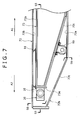
- Fig. 7 is an enlarged partially sectional view of the second jib structure 72 and the third jib structure 73 in the base end portion of the auxiliary jib 7 shown in Fig. 2 .
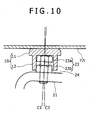
- Fig. 8 is a partially sectional arrow view by the line S5-S5 in Fig. 7 , showing a cross section of the second jib structure 72 and the sliding pad 10.
- Fig. 9 is a partially sectional arrow view by the line S6-S6 in Fig. 7 , showing a cross section of the second jib structure 72.
- the third jib structure 73 is provided with an inclined wall portion 73t inclined so as to come apart from a lower portion 72a of the second jib structure 72 as closer to the base end side, in the vicinity of a base end portion.
- a roller 90 having a rotation axis extending in the width direction of the third jib structure 73.
- the base end portion of the third jib structure 73 is supported by the lower portion 72a of the second jib structure 72 by the roller 90.
- sliding pads 91 substantially formed into a rectangular shape extending in parallel with the longitudinal direction of the third jib structure 73.
- the sliding pads 91 are formed so as to slide on the upper portion 72b of the second jib structure 72. It should be noted that the sliding pad 91 is fixed to the upper portion 73b of the third jib structure 73 at two points in the longitudinal direction.
- the bracket 20 extending from the end surface 73e in the stowing direction is integrally formed.
- the bracket 20 is formed of a steel plate substantially curved in a U shape and it is provided with a pair of supporting walls 21 extending in parallel from the end surface 73e of the base end portion of the third jib structure 73 in the width direction with leaving a predetermined clearance, and a coupling wall 22 for linking front ends of a pair of the supporting walls to each other.
- the bracket 20 is fixed to the end surface 73e of the base end portion of the third jib structure 73 by welding, for example.
- a pair of the supporting walls 21 are formed so as to oppose to each other in a clearance narrower than a width of the third jib structure 73.
- the supporting walls 21 are formed so that the clearance is approximately one half of the width of the third jib structure 73.
- an opening portion 72h In the inclined wall portion 72t of the second jib structure 72 is formed an opening portion 72h.
- the opening portion 72h is an opening with a diameter of approximately 100mm, and formed at a position where the outside of the second jib structure 72 are linearly communicated to the bracket 20 through the opening portion 72h.
- the opening portion 72h is formed so as to include at least a part of a position where the bracket 20 is orthographically projected to the inclined wall portion 72t.
- the lower portion 71a of the first jib structure 71 has an opening portion 71h at a position in the vicinity of the opening portion 72h of the second jib structure 72.
- the outside of the auxiliary jib 7 is linearly communicated to the bracket 20 and the sliding pad 10 installed in the bracket 20 through the opening portions 71h and 72h.
- a screw hole 21a passing through the supporting wall 21 in the width direction.
- a pad supporting bolt 23 (supporting member) having a head portion 23a and an axis portion 23b.
- the pad supporting bolt 23 is screwed so that the head portion 23a protrudes towards an inner surface 72i of the second jib structure 72 from a surface of the supporting wall 21 opposing to the inner surface 72i of the second jib structure 72.
- a nut 24 is fastened for fixing a position of the pad supporting bolt 23.
- a position of the sliding pad 10 installed and fitted so as to house the head portion 23a described later is properly adjusted. That is, a clearance between a sliding surface 11a of the sliding pad 10 and the inner surface 72i of the second jib structure 72 is adjusted.
- the sliding pad 10 formed into a cap shape is fitted into the pad supporting bolt 23 so as to cover the head portion 23a.
- the sliding pad 10 has a pad head portion 11 having the sliding surface 11a sliding on the inner surface 72i of the second jib structure 72, and a pad body portion 12 formed in a hollow shape and extending from an end on the opposite side of the sliding surface 11a in the pad head portion 11.
- An edge portion of the sliding surface 11a in the pad head portion 11 is formed into a curved surface.
- An inner diameter of the pad body portion 12 is formed larger than an outer diameter of the head portion 23a so as to make predetermined clearance between the pad body portion 12 and the head portion23a when the pad body portion 12 is fitted into the head portion 23a of the pad supporting bolt 23.
- the outer diameter of the head portion 23a is approximately 24mm, while the inner diameter of the pad body portion 12 is formed to be approximately 25mm. That is, the inner diameter of the pad body portion 12 is formed approximately 1mm larger than the outer diameter of the head portion 23a.
- the positions of the head portions 23a are adjusted so that a clearance between the sliding surfaces 11a located on the both sides of the third jib structure 73 is wider than a clearance in the width direction between outer surfaces 73i of the third jib structure 73, and so that the clearance is approximately 2mm to 3mm narrower than a clearance in the width direction between the inner surfaces 72i of the second jib structure 72 (approximately 200mm).
- the adjustment is desirably performed so that a pair of the sliding pads 10 are located substantially symmetrically about a central surface in the width direction of the third jib structure 73.
- the sliding pad 10 and the inner surface 72i of the second jib structure 72 are brought into abutment with each other. Thereby, movement of the third jib structure 73 in the width direction is within a predetermined range, and it is possible to reduce sliding resistance of the third jib structure 73 and the second jib structure 72.
- the first jib structure 71 is a jib structure located on the outermost side in the auxiliary jib 7. Therefore, a supporting member of the sliding pads 81, 82 and 84 and a positioning member such as a bolt can protrude outwards.
- the sliding pads 87 and 88 provided in the second jib structure 72 are always provided in the second jib structure 72 extending towards the outside of the first jib structure 71 in order to guide sliding movement of the third jib structure 73 inside the second jib structure 72.
- the sliding pad 10 is attached to the third jib structure 73 and the third jib structure 73 can slide on the inner surface 72i of the second jib structure 72.
- the sliding pad 10 in an extendable and stowable jib having at least three jib structures telescopically inserted into each other, is particularly effective in the case where the sliding pad is mounted to the base end portions of the jib structure which at least two jib structures are arranged in the outer sides thereof.
- the sliding pad for a jib according to the first embodiment is applied to the extendable and stowable auxiliary jib 7 having the three jib structures 71, 72 and 73 which are telescopically inserted into each other.
- the above sliding pad for a jib is disposed between the third jib structure 73 and the second jib structure 72, and movable with sliding on the inner surface 72i of the second jib structure 72.
- the pad supporting bolt 23 protruding towards the inner surface 72i of the second jib structure 72.
- the sliding pad 10 is fitted into the pad supporting bolt 23 so as to restrict movement of them in the perpendicular direction to the protruding direction of the pad supporting bolt 23. That is, when the third jib structure 73 is moved in the extending direction or the stowing direction, the sliding pad 10 is moved together with the pad supporting bolt 23 installed in the third jib structure 73.
- the sliding pad 10 is attached in a state of being sandwiched by the second jib structure 72 and the pad supporting bolt 23 in the protruding direction of the pad supporting bolt 23, and their movement in the protruding direction is restricted by the second jib structure 72.
- the movement of the sliding pad 10 is restricted by bringing the inner surface of the pad body portion 12 into abutment with the pad supporting bolt 23. Thereby, it is possible to surely prevent dropping-off of the sliding pad 10.
- the pad supporting bolt 23 is installed in the third jib structure 73, and it is possible to mount the sliding pad 10 to the third jib structure 73 through the pad supporting bolt 23. Therefore, there is no need for forming an excessively large hole which lowers strength of the third jib structure 73 in the third jib structure 73. Thereby, by the mounting of the sliding pad 10, it is possible to prevent the lowering of the strength of the third jib structure 73.
- the sliding pad 10 is formed as a cap-shaped pad having an opening end provided with the pad head portion 11 having the sliding surface 11a sliding on the inner surface 72i of the second jib structure 72, and having the pad body portion 12 formed in a hollow shape, the pad body portion 12 extending from the end on the opposite side of the sliding surface 11a in the pad head portion 11.
- the pad body portion 12 is fitted onto a front end of the pad supporting bolt 23.
- the protruding length of the pad supporting bolt 23 from the bracket 20 towards the inner surface 72i of the second jib structure 72 is adjustable. Therefore, by adjusting the protruding length of the pad supporting bolt 23, it is possible to adjust a clearance between the sliding surface 11a of the sliding pad 10 covered on the pad supporting bolt 23 and the inner surface 72i of the second jib structure 72.
- the pad supporting bolt 23 in which a male screw is threaded on the axis portion 23b is formed as an axial shape member.
- the pad supporting bolt 23 is screwed into the screw hole 21a formed in the bracket 20 provided in an end of the third jib structure 73. Therefore, by rotating the pad supporting bolt 23, the pad supporting bolt 23 is inserted into or out of the screw hole 21a so that the protruding length of the pad supporting bolt 23 from the bracket 20 can be continuously adjusted. Thereby, it is possible to continuously adjust the clearance between the sliding surface 11a of the sliding pad 10 by which the pad supporting bolt 23 is covered and the inner surface 72i of the second jib structure 72 with a simple mechanism, and adjustment is also easily and precisely performed.
- the clearance adjusting mechanism can be simply formed, it is possible to reduce the number of parts required for constituting the sliding pad, and it is possible to reduce manufacturing the cost. In comparison with the case where the clearance is adjusted by a shim or the like, a clearance adjustment operation can be more easily and rapidly performed.
- the opening portions 71h and 72h are formed on the wall surfaces of the first jib structure 71 on the outermost side in the auxiliary jib 7 and the second jib structure 72 disposed adjacent to and inside the first jib structure 71.
- the opening portions 71h and 72h are formed at a position where the outside of the auxiliary jib 7 are linearly communicated to the pad supporting bolt 23 through the opening portions 71h and 72h in a state that the auxiliary jib 7 is stowed.
- the third jib structure 73 is provided with the bracket 20 extending from the end surface 73e of the base end portion in the stowing direction.
- the bracket 20 has a pair of the supporting walls 21 opposing to each other in a clearance narrower than a width of the third jib structure 73 and extending in substantially parallel with the extending direction of the auxiliary jib 7.
- the pad supporting bolt 23 is screwed into the screw hole 21a formed in the supporting walls 21.
- a pair of the supporting walls 21 are arranged in the clearance narrower than the width of the third jib structure 73, and it is possible to widen the clearance between the supporting wall 21 and the inner surface 72i of the second jib structure 72.
- the sliding pad 10 and the head portion 23a of the pad supporting bolt 23 are fitted to each other so as to have a predetermined clearance in the radial direction. Therefore, within the pad body portion 12, inclination of the pad supporting bolt 23 is allowable to a predetermined extent.
- the above inclination indicates inclination of the axis portion 23b to a cylindrical axis of the pad body portion 12.
- the clearance between the sliding surfaces 11a of the sliding pad 10 is formed wider than the clearance in the width direction between the outer surfaces 73i of the third jib structure 73. Therefore, it is possible to prevent that the outer surface 73i of the third jib structure 73 is brought into abutment with the inner surface 72i of the second jib structure 72.
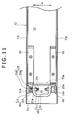
- Figs. 11 and 12 are partially sectional views showing an attachment structure of a sliding pad for a jib according to the second embodiment.
- Figs. 11 and 12 respectively correspond to Fig. 8 of the sectional arrow view by the line S5-S5 and Fig. 9 of the sectional arrow view by the line S6-S6 in Fig. 7 used in the description of the first embodiment.
- the sliding pad for a jib according to the second embodiment is different from the sliding pad according to the first embodiment in terms of a configuration of the pad supporting bolt 23 for supporting the sliding pad 10 in the first embodiment.
- Other configurations of the auxiliary jib 7 are the same as in the first embodiment.
- the same members are given the same reference numerals as the first embodiment and an explanation thereof will be omitted.
- a pad supporting bolt 25 has a head portion 25a and an axis portion 25b, and screwed into the screw hole 21a formed in the supporting wall 21 of the bracket 20.
- the pad supporting bolt 25 is screwed into the screw hole 21a so that an end of on the opposite side of the head portion 25a in the axis portion 25b extends from the supporting wall 21 to the central portion in width of the third jib structure 73.
- a plan portion 25c (engaging portion) chamfered symmetrically about the axis is partially formed.
- the axis portion 25b arranged on the opposite side of the head portion 25a sandwiching the supporting wall 21 is fastened by a nut 26 for fixing a position of the pad supporting bolt 25. It should be noted , as well as the first embodiment, that the pad supporting bolt 25 is screwed so that the head portion 25a protrudes from the surface of the supporting wall 21 opposing to the inner surface 72i of the second jib structure 72 towards the inner surface 72i of the second jib structure 72.
- the pad supporting bolt 25 is attached so that the protruding length thereof towards the inner surface 72i of the second jib structure 72 is adjustable from the inside of the bracket 20. That is, by loosening the nut 26 installed in the axis portion 25b extending to the central portion in width of the third jib structure 73, engaging a tool such as a spanner with the plan portion 25c formed in an end of the axis portion 25b and rotating the pad supporting bolt 25 to the screw hole, the protruding length of the head portion 25a is adjustable from the inside of the bracket 20.
- the protruding length of the head portion 25a is adjustable from the inside of the bracket 20 to which the pad supporting bolt 25 is attached in a state that the sliding pad 10 is attached to the pad supporting bolt 25.
- the protruding length of the head portion 25a is adjustable from the surface side opposite to the surface on the side opposing to the second jib structure 72 in the supporting wall 21, the protruding length of the head portion 25a is adjustable. Thereby, the adjustment of the clearance between the sliding surface 11a of the sliding pad 10 and the inner surface 72i of the second jib structure 72 is easily performed.
- a male screw is threaded over the substantially entire area of the axis portion 25b, and the pad supporting bolt 25 is formed as an axial shape member as a whole.
- the pad supporting bolt 25 is screwed into the screw hole 21a formed in the bracket 20 provided in the third jib structure 73 in a state that one end of the axis portion 25b protrudes towards the inside of the bracket 20.
- the plan portion 25c which is used when the pad supporting bolt 25 is rotated around the axis. It should be noted that the axis portion 25b has at least two plan portions 25c in parallel with each other.
- the end of the axis portion 25b of the pad supporting bolt 25 protrudes towards the central portion in width of the third jib structure 73, and the plan portion 25c is provided in the end. Therefore, it is possible to easily give a rotation force to the pad supporting bolt 25 by engaging the tool such as a spanner with the chamfered plan portion 25c. Thereby, since an operation of rotating and moving the pad supporting bolt 25 to the third jib structure 73 is easily performed, it is possible to efficiently adjust the clearance between the sliding surface 11a of the sliding pad 10 and the inner surface 72i of the second jib structure 72.
- the present invention is not limited to the case where the plan portion 25c is formed by cutting out the end of the axis portion 25b, but an engaging member which is used when the pad supporting bolt 25 is rotated around the axis may be fixed to the end of the axis portion 25b.
- the pad supporting bolt 25 has a function of the supporting member for supporting the sliding pad 10, as well as a function of the positioning member for adjusting the position of the sliding pad 10. Thereby, it is possible to reduce the number of parts of the sliding pad capable of adjusting the position of the sliding pad 10.
- the opening portions 71h and 72h are formed in the first jib structure 71 and the second jib structure 72 located on the outside of the third jib structure 73. Therefore, in a state that the auxiliary jib 7 is stowed, it is possible to rotate the pad supporting bolt 25 by the tool or the like through the opening portions 71h and 72h. Thereby, it is possible to further improve workability of adjusting the clearance.
- the size of the opening portions 71h and 72h are formed so that the tool is insertable.
- a lid for covering the opening portions 71h and 72h can be provided so as to make them closed except for while adjusting the clearance and performing the maintenance. Thereby, it is possible to prevent sand, water and the like from penetrating into the inside of the jib structure through the opening portions 71h and 72h.
- the present invention is not limited to a configuration that the bracket is provided in the base end portion of the jib structure and the supporting member for supporting the sliding pad such as the pad supporting bolt is attached to the bracket as in the present embodiment.
- a screw hole may be formed on a pair of left and right side walls forming a main body of a jib structure extending in the longitudinal direction so that the supporting member is attached.
- the axis portion of the pad supporting bolt extending towards the inside of the jib structure that is, the space sandwiched by a pair of the left and right side walls, is installed and the rotation force is added to the extending axis portion, then it is possible to easily adjust the position of the sliding pad fitted into the head portion of the pad supporting bolt from the inside of the jib structure.
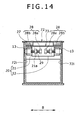
- Figs. 13 and 14 are partially sectional views showing a sliding pad for a jib according to the third embodiment.
- Figs. 13 and 14 respectively correspond to Fig. 8 of the sectional arrow view by the line S5-S5 and Fig. 9 of the sectional arrow view by the line S6-S6 in Fig. 7 used in the description of the first embodiment.
- the sliding pad for a jib according to the third embodiment is different from the sliding pad according to the first embodiment in terms of a configuration of the sliding pad 10 and the pad supporting bolt 23 in the first embodiment.
- Other configurations of the auxiliary jib 7 are the same as in the first embodiment.
- the same members are given the same reference numerals as the first embodiment and an explanation thereof will be omitted.
- a hollow supporting member 27 in a cylindrical shape is joined to a surface on the side opposing to the inner surface 72i of the second jib structure 72.
- the hollow supporting member 27 is installed so that a cylindrical center axis is substantially coaxial to a center axis of the screw hole 21a. It should be noted that the hollow supporting member 27 is joined to the bracket 20 by welding, for example.
- a bolt 28 (positioning member) is screwed into the screw hole 21a.
- the bolt 28 is screwed into the screw hole 21a so that a head portion 28a is located on the central portion in width of the third jib structure 73.
- An end of an axis portion 28b can protrude from the supporting wall 21 towards the side of the inner surface 72i of the second jib structure 72.
- a sliding pad 13 is formed into a substantially columnar shape whose outer diameter is approximately 1mm smaller than an inner diameter of the hollow supporting member 27.
- the sliding pad 13 is fitted into the inside of the hollow supporting member 27 in a state that a sliding surface 13a serving as an end surface substantially orthogonal to the columnar axial direction faces to the inner surface 72i of the second jib structure 72.
- An edge portion of the sliding surface 13a is formed into a curved surface.
- An end surface 13b on the opposite side of the sliding surface 13a is brought into abutment with the end of the axis portion 28b of the bolt 28 screwed into the screw hole 21a so that movement of the sliding pad 13 to the side of the supporting wall 21 is restricted.
- the supporting member for supporting the sliding pad 13 is formed as the hollow supporting member 27 extending towards the inner surface 72i of the second jib structure 72.
- the sliding pad 13 is formed into a columnar shape with one end serving as the sliding surface 13a, and fitted into the inside of the hollow supporting member 27 so that the sliding surface 13a protrudes outwards.
- the sliding pad 13 is formed so that a columnar height of the sliding pad 13 formed into a columnar shape is substantially the same as a columnar height of the hollow supporting member 27 formed into a cylindrical shape.
- the axis portion 28b of the bolt 28 protrudes from the supporting wall 21 towards the inside of the hollow supporting member 27 so that the sliding surface 13a of the sliding pad 13 is in a state of protruding outwards from the hollow supporting member 27. Therefore, it is possible to prevent that the hollow supporting member 27 is brought into abutment with the inner surface 72i of the second jib structure 72.
- the bolt 28 serving as the positioning member for supporting the end surface 13b on the opposite side of the sliding surface 13a in the sliding pad 13 is provided.
- the bolt 28 is formed as an axial shape member in which a male screw is threaded on the axis portion 28b thereof, and the bolt 28 is screwed into the screw hole 21a formed in the bracket 20 provided in the third jib structure 73 so as to move coaxially to the hollow supporting member 27.
- An extendable and stowable jib (7) comprises a plurality of jib structures (71, 72 and 73) telescopically inserted into each other.
- a sliding pad (10) sliding on an inner surface (72i) of an outer jib structure (72) is attached to the base end portion of an inner jib structure (73).
- the inner jib structure (73) is provided with a supporting member (23) protruding towards the inner surface (72i) of the outer jib structure (72).
- the sliding pad (10) is connected to the supporting member (23) so as to restrict movement in the perpendicular direction to the protruding direction of the supporting member (23).
- the present invention can prevent from damaging the jib structure due to a screw and drop-off of the sliding pad.
- the present invention does not lower strength of the jib structure.
Landscapes
- Engineering & Computer Science (AREA)
- Mechanical Engineering (AREA)
- Jib Cranes (AREA)
Applications Claiming Priority (1)
| Application Number | Priority Date | Filing Date | Title |
|---|---|---|---|
| JP2007109488A JP4333772B2 (ja) | 2007-04-18 | 2007-04-18 | ジブ用スライドパッド取付構造 |
Publications (2)
| Publication Number | Publication Date |
|---|---|
| EP1982948A2 true EP1982948A2 (fr) | 2008-10-22 |
| EP1982948A3 EP1982948A3 (fr) | 2010-10-27 |
Family
ID=39689482
Family Applications (1)
| Application Number | Title | Priority Date | Filing Date |
|---|---|---|---|
| EP08152244A Withdrawn EP1982948A3 (fr) | 2007-04-18 | 2008-03-04 | Tampon glissant pour flèche |
Country Status (2)
| Country | Link |
|---|---|
| EP (1) | EP1982948A3 (fr) |
| JP (1) | JP4333772B2 (fr) |
Cited By (6)
| Publication number | Priority date | Publication date | Assignee | Title |
|---|---|---|---|---|
| ITMO20120019A1 (it) * | 2012-01-27 | 2013-07-28 | Cosben S R L | Braccio telescopico |
| ITMO20130158A1 (it) * | 2013-05-31 | 2014-12-01 | Cnh Italia Spa | Dispositivo anti-usura regolabile per un braccio telescopico. |
| EP3431667A1 (fr) * | 2017-07-13 | 2019-01-23 | CNH Industrial Belgium NV | Système de patin d'usure |
| WO2021234066A1 (fr) * | 2020-05-20 | 2021-11-25 | Siemens Aktiengesellschaft | Montant télescopique pour un dispositif destiné à soulever des charges |
| RU2796336C1 (ru) * | 2020-05-20 | 2023-05-22 | Сименс Акциенгезелльшафт | Телескопическая стойка для устройства для подъема грузов |
| GB2620454A (en) * | 2022-07-08 | 2024-01-10 | Caterpillar Inc | Wear pad assembly |
Citations (2)
| Publication number | Priority date | Publication date | Assignee | Title |
|---|---|---|---|---|
| JPS6116306A (ja) | 1984-07-02 | 1986-01-24 | Nippon Atom Ind Group Co Ltd | プラントの非常用系自動試験装置 |
| JPH0735484U (ja) | 1993-12-13 | 1995-07-04 | 株式会社神戸製鋼所 | 伸縮ブーム |
Family Cites Families (3)
| Publication number | Priority date | Publication date | Assignee | Title |
|---|---|---|---|---|
| US4337601A (en) * | 1980-04-24 | 1982-07-06 | Harnischfeger Corporation | High-strength light-weight boom section for telescopic crane boom |
| US4759452A (en) * | 1987-02-20 | 1988-07-26 | Faint Richard C | Articulated load bearing wear pad assembly |
| US5865328A (en) * | 1993-06-16 | 1999-02-02 | Ec Engineering + Consulting Spezialmaschinen Gmbh | Telescopic boom |
-
2007
- 2007-04-18 JP JP2007109488A patent/JP4333772B2/ja not_active Expired - Fee Related
-
2008
- 2008-03-04 EP EP08152244A patent/EP1982948A3/fr not_active Withdrawn
Patent Citations (2)
| Publication number | Priority date | Publication date | Assignee | Title |
|---|---|---|---|---|
| JPS6116306A (ja) | 1984-07-02 | 1986-01-24 | Nippon Atom Ind Group Co Ltd | プラントの非常用系自動試験装置 |
| JPH0735484U (ja) | 1993-12-13 | 1995-07-04 | 株式会社神戸製鋼所 | 伸縮ブーム |
Cited By (9)
| Publication number | Priority date | Publication date | Assignee | Title |
|---|---|---|---|---|
| ITMO20120019A1 (it) * | 2012-01-27 | 2013-07-28 | Cosben S R L | Braccio telescopico |
| ITMO20130158A1 (it) * | 2013-05-31 | 2014-12-01 | Cnh Italia Spa | Dispositivo anti-usura regolabile per un braccio telescopico. |
| WO2014191561A1 (fr) * | 2013-05-31 | 2014-12-04 | Cnh Industrial Italia S.P.A. | Ensemble plaque d'usure réglable destiné à une flèche télescopique |
| US9950911B2 (en) | 2013-05-31 | 2018-04-24 | Cnh Industrial America Llc | Adjustable wear pad assembly for a telescopic boom |
| EP3431667A1 (fr) * | 2017-07-13 | 2019-01-23 | CNH Industrial Belgium NV | Système de patin d'usure |
| WO2021234066A1 (fr) * | 2020-05-20 | 2021-11-25 | Siemens Aktiengesellschaft | Montant télescopique pour un dispositif destiné à soulever des charges |
| RU2796336C1 (ru) * | 2020-05-20 | 2023-05-22 | Сименс Акциенгезелльшафт | Телескопическая стойка для устройства для подъема грузов |
| GB2620454A (en) * | 2022-07-08 | 2024-01-10 | Caterpillar Inc | Wear pad assembly |
| GB2620454B (en) * | 2022-07-08 | 2024-11-27 | Caterpillar Inc | Wear pad assembly |
Also Published As
| Publication number | Publication date |
|---|---|
| JP4333772B2 (ja) | 2009-09-16 |
| JP2008265928A (ja) | 2008-11-06 |
| EP1982948A3 (fr) | 2010-10-27 |
Similar Documents
| Publication | Publication Date | Title |
|---|---|---|
| EP1982948A2 (fr) | Tampon glissant pour flèche | |
| EP3348714B1 (fr) | Dispositif de vérin | |
| CA2465464C (fr) | Dispositif de flexion du pinacle pliant | |
| US12371307B2 (en) | Mobile telescopic hydraulic crane | |
| CN108529454A (zh) | 用于吊臂收纳的吊臂联接系统 | |
| KR101487459B1 (ko) | 휴대형 파이프 적입 장치 | |
| EP1992584B1 (fr) | Appareil pour amarrer une flèche | |
| JP2019073391A (ja) | 伸縮ブーム | |
| JP5166352B2 (ja) | 多段伸縮ブーム | |
| EP3650394A1 (fr) | Dispositif de retenue pour outil de manutention de charges et grue hydraulique comprenant un tel dispositif de retenue | |
| CN118617395A (zh) | 助力机械臂 | |
| EP2096075A1 (fr) | Poutre télescopique | |
| JP3160176U (ja) | リフト用スイングアーム構造 | |
| RU99100199A (ru) | Крано-манипуляторная установка | |
| WO2011028155A1 (fr) | Bielle de direction pour un véhicule et véhicule avec une bielle de direction | |
| KR101716501B1 (ko) | 틸팅캐빈이 설치된 중장비용 호스가이드 | |
| FR3112993B1 (fr) | Timon rétractable | |
| EP4269317B1 (fr) | Extrémité de grue et agencement de connexion | |
| JP2010037045A (ja) | 筒型構造体 | |
| EP1373120A1 (fr) | Fleche telescopique pour une grue automotrice | |
| EP3099621B1 (fr) | Grue de levage dotée d'un mécanisme d'élévation de mat | |
| CN103086284B (zh) | 自导向伸缩臂装置 | |
| EP3524564B1 (fr) | Grue pour déplacer des charges | |
| JP7300178B2 (ja) | 吹流し用ポール固定台 | |
| CN212403325U (zh) | 应用于支撑结构的收折装置 |
Legal Events
| Date | Code | Title | Description |
|---|---|---|---|
| PUAI | Public reference made under article 153(3) epc to a published international application that has entered the european phase |
Free format text: ORIGINAL CODE: 0009012 |
|
| 17P | Request for examination filed |
Effective date: 20080304 |
|
| AK | Designated contracting states |
Kind code of ref document: A2 Designated state(s): AT BE BG CH CY CZ DE DK EE ES FI FR GB GR HR HU IE IS IT LI LT LU LV MC MT NL NO PL PT RO SE SI SK TR |
|
| AX | Request for extension of the european patent |
Extension state: AL BA MK RS |
|
| PUAL | Search report despatched |
Free format text: ORIGINAL CODE: 0009013 |
|
| AK | Designated contracting states |
Kind code of ref document: A3 Designated state(s): AT BE BG CH CY CZ DE DK EE ES FI FR GB GR HR HU IE IS IT LI LT LU LV MC MT NL NO PL PT RO SE SI SK TR |
|
| AX | Request for extension of the european patent |
Extension state: AL BA MK RS |
|
| AKX | Designation fees paid |
Designated state(s): AT BE BG CH CY CZ DE DK EE ES FI FR GB GR HR HU IE IS IT LI LT LU LV MC MT NL NO PL PT RO SE SI SK TR |
|
| 17Q | First examination report despatched |
Effective date: 20140926 |
|
| STAA | Information on the status of an ep patent application or granted ep patent |
Free format text: STATUS: THE APPLICATION IS DEEMED TO BE WITHDRAWN |
|
| 18D | Application deemed to be withdrawn |
Effective date: 20150207 |