EP1981013A1 - Messsteuerung für ein Fahrzeug - Google Patents
Messsteuerung für ein Fahrzeug Download PDFInfo
- Publication number
- EP1981013A1 EP1981013A1 EP08013876A EP08013876A EP1981013A1 EP 1981013 A1 EP1981013 A1 EP 1981013A1 EP 08013876 A EP08013876 A EP 08013876A EP 08013876 A EP08013876 A EP 08013876A EP 1981013 A1 EP1981013 A1 EP 1981013A1
- Authority
- EP
- European Patent Office
- Prior art keywords
- vehicle
- time
- processing
- measuring
- radar
- Prior art date
- Legal status (The legal status is an assumption and is not a legal conclusion. Google has not performed a legal analysis and makes no representation as to the accuracy of the status listed.)
- Granted
Links
- 238000012545 processing Methods 0.000 claims abstract description 157
- 230000005540 biological transmission Effects 0.000 abstract description 15
- 238000000034 method Methods 0.000 abstract description 13
- 238000005259 measurement Methods 0.000 description 16
- 238000010586 diagram Methods 0.000 description 14
- 230000007274 generation of a signal involved in cell-cell signaling Effects 0.000 description 6
- 238000005070 sampling Methods 0.000 description 3
- 238000006243 chemical reaction Methods 0.000 description 1
- 238000002485 combustion reaction Methods 0.000 description 1
- 238000004891 communication Methods 0.000 description 1
- 238000007796 conventional method Methods 0.000 description 1
- 238000011161 development Methods 0.000 description 1
- 230000010355 oscillation Effects 0.000 description 1
- 230000000630 rising effect Effects 0.000 description 1
- 230000001360 synchronised effect Effects 0.000 description 1
- 230000009466 transformation Effects 0.000 description 1
Images


Classifications
-
- G—PHYSICS
- G01—MEASURING; TESTING
- G01S—RADIO DIRECTION-FINDING; RADIO NAVIGATION; DETERMINING DISTANCE OR VELOCITY BY USE OF RADIO WAVES; LOCATING OR PRESENCE-DETECTING BY USE OF THE REFLECTION OR RERADIATION OF RADIO WAVES; ANALOGOUS ARRANGEMENTS USING OTHER WAVES
- G01S13/00—Systems using the reflection or reradiation of radio waves, e.g. radar systems; Analogous systems using reflection or reradiation of waves whose nature or wavelength is irrelevant or unspecified
- G01S13/86—Combinations of radar systems with non-radar systems, e.g. sonar, direction finder
- G01S13/867—Combination of radar systems with cameras
-
- B—PERFORMING OPERATIONS; TRANSPORTING
- B60—VEHICLES IN GENERAL
- B60W—CONJOINT CONTROL OF VEHICLE SUB-UNITS OF DIFFERENT TYPE OR DIFFERENT FUNCTION; CONTROL SYSTEMS SPECIALLY ADAPTED FOR HYBRID VEHICLES; ROAD VEHICLE DRIVE CONTROL SYSTEMS FOR PURPOSES NOT RELATED TO THE CONTROL OF A PARTICULAR SUB-UNIT
- B60W10/00—Conjoint control of vehicle sub-units of different type or different function
- B60W10/04—Conjoint control of vehicle sub-units of different type or different function including control of propulsion units
- B60W10/06—Conjoint control of vehicle sub-units of different type or different function including control of propulsion units including control of combustion engines
-
- B—PERFORMING OPERATIONS; TRANSPORTING
- B60—VEHICLES IN GENERAL
- B60W—CONJOINT CONTROL OF VEHICLE SUB-UNITS OF DIFFERENT TYPE OR DIFFERENT FUNCTION; CONTROL SYSTEMS SPECIALLY ADAPTED FOR HYBRID VEHICLES; ROAD VEHICLE DRIVE CONTROL SYSTEMS FOR PURPOSES NOT RELATED TO THE CONTROL OF A PARTICULAR SUB-UNIT
- B60W10/00—Conjoint control of vehicle sub-units of different type or different function
- B60W10/10—Conjoint control of vehicle sub-units of different type or different function including control of change-speed gearings
-
- B—PERFORMING OPERATIONS; TRANSPORTING
- B60—VEHICLES IN GENERAL
- B60W—CONJOINT CONTROL OF VEHICLE SUB-UNITS OF DIFFERENT TYPE OR DIFFERENT FUNCTION; CONTROL SYSTEMS SPECIALLY ADAPTED FOR HYBRID VEHICLES; ROAD VEHICLE DRIVE CONTROL SYSTEMS FOR PURPOSES NOT RELATED TO THE CONTROL OF A PARTICULAR SUB-UNIT
- B60W10/00—Conjoint control of vehicle sub-units of different type or different function
- B60W10/18—Conjoint control of vehicle sub-units of different type or different function including control of braking systems
- B60W10/184—Conjoint control of vehicle sub-units of different type or different function including control of braking systems with wheel brakes
-
- B—PERFORMING OPERATIONS; TRANSPORTING
- B60—VEHICLES IN GENERAL
- B60W—CONJOINT CONTROL OF VEHICLE SUB-UNITS OF DIFFERENT TYPE OR DIFFERENT FUNCTION; CONTROL SYSTEMS SPECIALLY ADAPTED FOR HYBRID VEHICLES; ROAD VEHICLE DRIVE CONTROL SYSTEMS FOR PURPOSES NOT RELATED TO THE CONTROL OF A PARTICULAR SUB-UNIT
- B60W30/00—Purposes of road vehicle drive control systems not related to the control of a particular sub-unit, e.g. of systems using conjoint control of vehicle sub-units
- B60W30/14—Adaptive cruise control
- B60W30/16—Control of distance between vehicles, e.g. keeping a distance to preceding vehicle
-
- G—PHYSICS
- G01—MEASURING; TESTING
- G01S—RADIO DIRECTION-FINDING; RADIO NAVIGATION; DETERMINING DISTANCE OR VELOCITY BY USE OF RADIO WAVES; LOCATING OR PRESENCE-DETECTING BY USE OF THE REFLECTION OR RERADIATION OF RADIO WAVES; ANALOGOUS ARRANGEMENTS USING OTHER WAVES
- G01S13/00—Systems using the reflection or reradiation of radio waves, e.g. radar systems; Analogous systems using reflection or reradiation of waves whose nature or wavelength is irrelevant or unspecified
- G01S13/02—Systems using reflection of radio waves, e.g. primary radar systems; Analogous systems
- G01S13/06—Systems determining position data of a target
- G01S13/08—Systems for measuring distance only
- G01S13/32—Systems for measuring distance only using transmission of continuous waves, whether amplitude-, frequency-, or phase-modulated, or unmodulated
- G01S13/34—Systems for measuring distance only using transmission of continuous waves, whether amplitude-, frequency-, or phase-modulated, or unmodulated using transmission of continuous, frequency-modulated waves while heterodyning the received signal, or a signal derived therefrom, with a locally-generated signal related to the contemporaneously transmitted signal
- G01S13/345—Systems for measuring distance only using transmission of continuous waves, whether amplitude-, frequency-, or phase-modulated, or unmodulated using transmission of continuous, frequency-modulated waves while heterodyning the received signal, or a signal derived therefrom, with a locally-generated signal related to the contemporaneously transmitted signal using triangular modulation
-
- G—PHYSICS
- G01—MEASURING; TESTING
- G01S—RADIO DIRECTION-FINDING; RADIO NAVIGATION; DETERMINING DISTANCE OR VELOCITY BY USE OF RADIO WAVES; LOCATING OR PRESENCE-DETECTING BY USE OF THE REFLECTION OR RERADIATION OF RADIO WAVES; ANALOGOUS ARRANGEMENTS USING OTHER WAVES
- G01S13/00—Systems using the reflection or reradiation of radio waves, e.g. radar systems; Analogous systems using reflection or reradiation of waves whose nature or wavelength is irrelevant or unspecified
- G01S13/02—Systems using reflection of radio waves, e.g. primary radar systems; Analogous systems
- G01S13/50—Systems of measurement based on relative movement of target
- G01S13/58—Velocity or trajectory determination systems; Sense-of-movement determination systems
- G01S13/583—Velocity or trajectory determination systems; Sense-of-movement determination systems using transmission of continuous unmodulated waves, amplitude-, frequency-, or phase-modulated waves and based upon the Doppler effect resulting from movement of targets
- G01S13/584—Velocity or trajectory determination systems; Sense-of-movement determination systems using transmission of continuous unmodulated waves, amplitude-, frequency-, or phase-modulated waves and based upon the Doppler effect resulting from movement of targets adapted for simultaneous range and velocity measurements
-
- G—PHYSICS
- G01—MEASURING; TESTING
- G01S—RADIO DIRECTION-FINDING; RADIO NAVIGATION; DETERMINING DISTANCE OR VELOCITY BY USE OF RADIO WAVES; LOCATING OR PRESENCE-DETECTING BY USE OF THE REFLECTION OR RERADIATION OF RADIO WAVES; ANALOGOUS ARRANGEMENTS USING OTHER WAVES
- G01S13/00—Systems using the reflection or reradiation of radio waves, e.g. radar systems; Analogous systems using reflection or reradiation of waves whose nature or wavelength is irrelevant or unspecified
- G01S13/88—Radar or analogous systems specially adapted for specific applications
- G01S13/93—Radar or analogous systems specially adapted for specific applications for anti-collision purposes
- G01S13/931—Radar or analogous systems specially adapted for specific applications for anti-collision purposes of land vehicles
- G01S2013/93185—Controlling the brakes
-
- G—PHYSICS
- G01—MEASURING; TESTING
- G01S—RADIO DIRECTION-FINDING; RADIO NAVIGATION; DETERMINING DISTANCE OR VELOCITY BY USE OF RADIO WAVES; LOCATING OR PRESENCE-DETECTING BY USE OF THE REFLECTION OR RERADIATION OF RADIO WAVES; ANALOGOUS ARRANGEMENTS USING OTHER WAVES
- G01S13/00—Systems using the reflection or reradiation of radio waves, e.g. radar systems; Analogous systems using reflection or reradiation of waves whose nature or wavelength is irrelevant or unspecified
- G01S13/88—Radar or analogous systems specially adapted for specific applications
- G01S13/93—Radar or analogous systems specially adapted for specific applications for anti-collision purposes
- G01S13/931—Radar or analogous systems specially adapted for specific applications for anti-collision purposes of land vehicles
- G01S2013/9319—Controlling the accelerator
-
- G—PHYSICS
- G01—MEASURING; TESTING
- G01S—RADIO DIRECTION-FINDING; RADIO NAVIGATION; DETERMINING DISTANCE OR VELOCITY BY USE OF RADIO WAVES; LOCATING OR PRESENCE-DETECTING BY USE OF THE REFLECTION OR RERADIATION OF RADIO WAVES; ANALOGOUS ARRANGEMENTS USING OTHER WAVES
- G01S13/00—Systems using the reflection or reradiation of radio waves, e.g. radar systems; Analogous systems using reflection or reradiation of waves whose nature or wavelength is irrelevant or unspecified
- G01S13/88—Radar or analogous systems specially adapted for specific applications
- G01S13/93—Radar or analogous systems specially adapted for specific applications for anti-collision purposes
- G01S13/931—Radar or analogous systems specially adapted for specific applications for anti-collision purposes of land vehicles
- G01S2013/932—Radar or analogous systems specially adapted for specific applications for anti-collision purposes of land vehicles using own vehicle data, e.g. ground speed, steering wheel direction
-
- G—PHYSICS
- G01—MEASURING; TESTING
- G01S—RADIO DIRECTION-FINDING; RADIO NAVIGATION; DETERMINING DISTANCE OR VELOCITY BY USE OF RADIO WAVES; LOCATING OR PRESENCE-DETECTING BY USE OF THE REFLECTION OR RERADIATION OF RADIO WAVES; ANALOGOUS ARRANGEMENTS USING OTHER WAVES
- G01S13/00—Systems using the reflection or reradiation of radio waves, e.g. radar systems; Analogous systems using reflection or reradiation of waves whose nature or wavelength is irrelevant or unspecified
- G01S13/88—Radar or analogous systems specially adapted for specific applications
- G01S13/93—Radar or analogous systems specially adapted for specific applications for anti-collision purposes
- G01S13/931—Radar or analogous systems specially adapted for specific applications for anti-collision purposes of land vehicles
- G01S2013/9321—Velocity regulation, e.g. cruise control
-
- G—PHYSICS
- G01—MEASURING; TESTING
- G01S—RADIO DIRECTION-FINDING; RADIO NAVIGATION; DETERMINING DISTANCE OR VELOCITY BY USE OF RADIO WAVES; LOCATING OR PRESENCE-DETECTING BY USE OF THE REFLECTION OR RERADIATION OF RADIO WAVES; ANALOGOUS ARRANGEMENTS USING OTHER WAVES
- G01S13/00—Systems using the reflection or reradiation of radio waves, e.g. radar systems; Analogous systems using reflection or reradiation of waves whose nature or wavelength is irrelevant or unspecified
- G01S13/88—Radar or analogous systems specially adapted for specific applications
- G01S13/93—Radar or analogous systems specially adapted for specific applications for anti-collision purposes
- G01S13/931—Radar or analogous systems specially adapted for specific applications for anti-collision purposes of land vehicles
- G01S2013/9323—Alternative operation using light waves
-
- G—PHYSICS
- G01—MEASURING; TESTING
- G01S—RADIO DIRECTION-FINDING; RADIO NAVIGATION; DETERMINING DISTANCE OR VELOCITY BY USE OF RADIO WAVES; LOCATING OR PRESENCE-DETECTING BY USE OF THE REFLECTION OR RERADIATION OF RADIO WAVES; ANALOGOUS ARRANGEMENTS USING OTHER WAVES
- G01S13/00—Systems using the reflection or reradiation of radio waves, e.g. radar systems; Analogous systems using reflection or reradiation of waves whose nature or wavelength is irrelevant or unspecified
- G01S13/88—Radar or analogous systems specially adapted for specific applications
- G01S13/93—Radar or analogous systems specially adapted for specific applications for anti-collision purposes
- G01S13/931—Radar or analogous systems specially adapted for specific applications for anti-collision purposes of land vehicles
- G01S2013/9325—Radar or analogous systems specially adapted for specific applications for anti-collision purposes of land vehicles for inter-vehicle distance regulation, e.g. navigating in platoons
Definitions
- the present invention relates to a measuring and controlling apparatus for a vehicle which measures a circumferential state of an automobile and controls the running of the automobile based on the measured result.
- some of measuring and controlling apparatuses for vehicles employ a method of radiating radio wave or light and measuring a distance to a target such as an automobile or obstacle ahead of the automobile and a relative speed with respect to the target.
- a camera is mounted on a vehicle, then the camera photographs or picks up an image of a vehicle ahead, and the image thus image picked-up or photographed is subjected to an image recognition processing thereby to recognize the vehicle ahead.
- JP-A-11-321379 A method in which a vehicle trying to cut in is detected in advance by using both the radar apparatus utilizing light or radio wave and the image processing apparatus utilizing a camera is described in JP-A-11-321379 .
- a method of improving recognition efficiency of a vehicle ahead is described in JP-A-6-231398 etc.
- JP-A-10-160835 describes a technique in which a camera and a scanning type laser radar are used in a manner that a beam of the laser radar is scanned in synchronism with the synchronizing signal of the camera, whereby even if plural vehicles ahead are photographed in an overlapped manner, distances to subjects within an image photographed by the camera are grasped on a pixel unit basis and an overlapped state of the plural vehicles ahead are recognized.
- a time length required for signal processing in each of the radar apparatus and the image processing apparatus becomes a delay time until the result of the signal processing is outputted after the signal is inputted into the apparatus.
- This processing time largely differs depending on an environment condition of the road.
- an object of the present invention is, in a measuring and controlling apparatus for a vehicle which performs a sensing operation by a radar apparatus or an image processing apparatus and controls the vehicle by using the sensing result, to realize the measuring and controlling apparatus for a vehicle which can control the vehicle at a high accuracy by taking into consideration of a variation of a time difference between a time point where the radar apparatus or the image processing apparatus measures or photographs and a time point where the signals from these apparatuses are processed.
- the present invention is configured as follows.
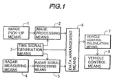
- Fig. 1 is a system diagram of a measuring and controlling apparatus for a vehicle according to the embodiment of the present invention.
- the measuring and controlling apparatus for a vehicle includes an image pick-up means 1 , an image processing means 2, a time signal generation means 3, a radar measuring means 4, a radar signal processing means 5, a data arrangement means 6, a vehicle control calculation means 7 and a vehicle control means 8.
- the image pick-up means (camera) 1 photographs or picks up an image of a status ahead of an own vehicle and sends information thus photographed to the image processing means 2.
- the image processing means 2 records an image input timing at which the mage is photographed in the form of a time signal from the time signal generation means 3.
- t(n) corresponds to the image input timing.
- the image processing means 2 executes a processing of recognizing a target recognition subject from the image information sent from the image pick-up means 1. After the completion of the recognition processing, the image processing means 2 outputs the recognition result to the data arrangement means 6.
- the radar measuring means 4 transmits and receives radio wave or light, and the radar signal processing means 5 processes transmission and receiving signals to calculate a distance between the own vehicle and a vehicle ahead and a relative speed.
- the radar signal processing means 5 records a signal input timing at which the measurement is performed by the radar measuring means 4 in the form of the time signal from the time signal generation means 3.
- t(n + m) corresponds to the radar input timing.
- the information of the distance and the relative speed calculated by the radar signal processing means 5 is outputted to the data arrangement means 6 after the completion of the radar signal processing.
- the image input timing t(n) at the camera 1 is earlier than the input timing t(n + m) at the radar 4.
- the data arrangement means 6 compares the time information t(n) sent in accompany with the camera information with the time information t(n + m) sent in accompany with the radar information, then changes the order of the camera information and the radar information in the originally measured order, and outputs the radar measurement information and the image recognition information to the vehicle control calculation means 7 in the order thus changed.
- the vehicle control calculation means 7 inputs the radar measurement information and the image recognition information together with their time information accompanied therewith, then performs calculation for the vehicle control and outputs an instruction for the vehicle control to the vehicle control means 8.
- the embodiment of the present invention is configured in a manner that the information measured by the radar and the information photographed by the camera are arranged in the order of the respective time point information of the measured and photographed timings thereby to perform the vehicle control.
- the measuring and controlling apparatus for a vehicle which performs the sensing operation by the radar apparatus and the image processing apparatus and controls the vehicle by using the sensing results, it is possible to realize the measuring and controlling apparatus for a vehicle which can control the vehicle at high accuracy by taking into consideration of a variation of a time difference between the time points where the radar apparatus and the image processing apparatus measures and photographs and the time point where the signals from these apparatuses are processed.
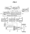
- Fig. 3 is a block diagram showing the system for controlling a distance to a vehicle ahead according to another embodiment of the present invention.
- an image pick-up apparatus 31 photographs or picks up an image of a state ahead of the own vehicle, then subjects a target subject thus photographed to an image processing and outputs the image thus processed.
- the image pick-up apparatus executes both the function of the image pick-up means 1 and the function of the image processing means 2 in Fig. 1 .
- the image pick-up apparatus 31 photographs an image
- the image pick-up apparatus records a time point where the image has been photographed based on the time signal from a time signal generation unit 33.
- the image pick-up apparatus 31 performs a processing of recognizing a target recognition subject from the image information, and outputs the image recognition information as the result of the recognition and the time information to a vehicle controller 32 after the completion of the recognition processing.
- a radar apparatus 30 transmits and receives radio wage or light to calculate a distance to a vehicle ahead and a relative speed with respect to the vehicle ahead. That is, the radar apparatus 30 executes both the function of the radar measuring means 4 and the function of the radar signal processing means 5 in Fig. 1 .
- the radar apparatus 30 records a time point where the subject has been measured by the radar based on the time signal from the time signal generation unit 33.
- the radar apparatus 30 outputs the information of the distance between the own vehicle and a vehicle ahead and the relative speed as the radar measurement information and the time information to the vehicle controller 32 after the completion of the radar measurement processing.
- the vehicle controller 32 has a function of calculating and outputting an instruction for controlling a speed of the vehicle based on the data of the distance to a vehicle ahead and the relative speed sent from the radar apparatus 30 and the image pick-up apparatus 31 and the respective time information.
- a sensor input data processing unit 34 within the vehicle controller 32 executes the function of the data arrangement means 6 in Fig. 1 and so executes a processing of reading the time information accompanied to the respective data sent from the radar apparatus 30 and the image pick-up apparatus 31 and arranging the respective data in the order of the respective time information.
- the respective information arranged in the order of the respective time information is sent to a vehicle control calculation unit 35.
- the vehicle control calculation unit 35 executes the function of the vehicle control calculation means 7 in Fig. 1 in a manner that an instruction for controlling a throttle valve, a transmission and a brake is outputted to a throttle valve controller 36, a transmission controller 37 and a brake controller 38 based on the sensing information inputted from the sensor input data processing unit 34 and speed information of the own vehicle etc. so that a speed of the own vehicle becomes a predetermined speed.
- the throttle valve controller 36 controls a throttle valve actuator 40 for operating the throttle valve of an internal combustion engine 41 based on an instruction from the vehicle controller 37.
- the transmission controller 37 controls a transmission 42 based on an instruction from the vehicle controller 37.
- the brake controller 38 controls a brake actuator 43.
- the throttle valve controller 36, the transmission controller 37 and the brake controller 38 execute the function of the vehicle control means 8 in Fig. 1 .
- the vehicle control with a high accuracy can be realized.
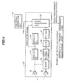
- Fig. 4 is a block diagram showing an example of the inner configuration of a radio wave radar which transmits radio wave and receives reflection wave thereof.
- a modulator 50 sends a modulation signal for the measurement by the radar to an oscillator 51, which in turn oscillates a high frequency signal having a frequency based on the modulation signal thus sent.
- the high frequency signal oscillated from the oscillator 51 is sent to a transmission antenna 52 and radiated therefrom.
- a radio wave signal of a millimeter wave band having a function of returning a reflection wave even from a small target is usually utilized as the high frequency signal.
- the receiving antenna 53 receives a radio wave signal reflected and returned from a target such as a vehicle, an obstacle etc., and the signal thus received is subject to a frequency conversion by a mixer 54.
- the mixer 54 is supplied with a part of the oscillation signal of the oscillator 51 through a directional coupler.
- a beat signal generated through the mixing operation with the signal from the oscillator 51 and the received signal from the antenna 54 is sent to an analog circuit unit 55.
- Fig. 5 shows an example of the transmission signal being modulated, the received signal and the beat signal having been mixed in the FMCW (frequency modulated continuous wave) method using the triangular-wave modulation.
- the frequency is deviated between the transmission signal and the receiving signal depending on a distance to a target and a relative speed with respect to the target.
- the distance to the target and the relative speed with respect to the target can be obtained from the deviation.
- the beat signal can be obtained at each of a rising section and a falling section of the rectangular wave.
- the beat signal thus obtained is converted into digital data by an A/D converter 56, then subjected to frequency analysis by an FET (fast Fourier transformation) unit 57 and then a signal processing unit 58 calculates the distance and the relative speed.
- FET fast Fourier transformation
- the information of the distance and the relative speed calculated by the signal processing unit 58 is added with the time information representing the measuring timing obtained from the time signal sent from the time signal generation unit 33 and the modulation timing signal at the time of the radio wave transmission, and these information added with the time information is outputted to the vehicle controller 32.
- Fig 4 also shows an example of radar measurement output data of the radar apparatus 30.
- the radar measurement output data is configured in a format having the measurement time information in addition to the measured data such as the distance to a vehicle ahead and the relative speed etc.
- the measuring timing in the radio wave radar may be an intermediate point of the sampling time of the data subjected to the FFT processing.
- Fig. 5 the triangular wave signal for the modulation and an example of the measuring timing are shown.
- the radio wave radar employs a method of continuously measuring the data for a predetermined time period in order to reduce measurement error due to the influence such as noise etc.
- the information of the distance and the relative speed at this time is outputted as decided information.
- an intermediate timing of the N times of the triangular wave modulation is used as the distance measurement timing of the radar.
- an example of the repetition number N of the triangular wave is set to be about 10 in ordinary environment.
- the vehicle control with higher accuracy can be realized by using this time information.
- Fig. 6 is a block diagram showing an example of the image pick-up apparatus 31 which photographs or picks up an image of a circumferential state by the camera, then subjects the photographed image to the image processing and outputs the recognition result.
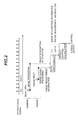
- Fig. 7 shows an example of the vertical synchronizing signal of the image and the image input timing.
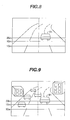
- Figs. 8 and 9 show examples of images for recognizing a vehicle trying to cut in.
- the image pick-up apparatus 31 shown in Fig. 6 includes an image pick-up unit 60 and an image processing unit 61.
- the image pick-up unit 60 photographs an image in the forward direction of the own vehicle.
- the image processing unit 61 processes the image thus photographed thereby to recognize a vehicle ahead, a traffic lane of the road etc.
- Figs. 8 and 9 show an example of the image in the case where a vehicle 91 trying to cut in exists at a point about 20 m ahead of the own vehicle.
- a CCD (charge coupled device) camera is used as the image pick-up unit 60, for example.
- the CCD camera photographs images of n (for example, 30) frames per second.
- the image data corresponding to the respective frames is transferred to the image processing unit 61.
- the respective frames are outputted in synchronous with the vertical synchronizing signal of the image.
- the output timings of the respective frames are shown in Fig. 7 . That is, the image signal photographed within the time section of a frame (i) is started to be outputted in response to the vertical synchronizing signal of the next frame (i + 1) serving as a trigger. After the completion of the output of the image signal of the frame (i), the image processing unit 61 executes the processing of recognizing the image photographed at the frame (i).
- the time information of the image input is sent to the vehicle controller 32 together with the image recognition information.
- the time information sent at this time represents the image input timing of the frame (i) where the image was photographed.
- Fig. 8 shows the example where only one vehicle exists ahead of the own vehicle. In this case, a time period required for the image processing is not so long.
- Fig. 9 shows the example where many vehicles and buildings exist ahead of the own vehicle. In this case, a time period required for the image processing becomes long. Although the time period required for the image processing differs depending on the ability of a signal processing processor, there is a case requiring several ten to several hundred m sec.
- the vehicle control with high accuracy can be realized by using this time information.
- the radar measurement information sent from the radar apparatus 30 is inputted, and at step 101, the image recognition information sent from the image pick-up apparatus 31 is inputted.
- the respective input information are arranged in the order of the time sequence of the respective measurement timings of the radar apparatus 30 and the image pick-up apparatus 31 based on the respective time information accompanied to the two input information.
- the radar measurement information and the image recognition information thus arranged in the order of the time sequence are outputted to the vehicle control calculation unit 35, and the process returns to step 100.
- the vehicle control calculation unit can treat data in the order of the measured time sequence even if the plural sensors are employed, the vehicle control with higher accuracy can be realized.
- the processing flowchart shown in Fig. 10 can be recorded on a recording medium as the control program for the measuring and controlling apparatus for a vehicle.
- a recording medium is an example of the embodiment of the present invention.
- the recording medium records therein the control program for the measuring and controlling apparatus for a vehicle which includes a first processing for processing the signal from the image pick-up means 1 which is mounted on the vehicle and photographs a circumferential state of the vehicle; a second processing for processing the signal from the radar measuring means 4 which radiates radio wave or light to measure a distance to a subject at the periphery of the vehicle; a time information adding processing for adding respective time information to the output information of the first processing and the output information of the second processing, respectively; a time adjusting processing for adjusting time order of the respective output information based on the time information contained in the output information of the first processing and the time information contained in the output information of the second processing; and a control processing for controlling at least one of the brake, the throttle valve and the transmission based on the output of the first processing and the output of the second processing subjected to the time adjusting processing.
- an automobile provided with the aforesaid measuring and controlling apparatus for a vehicle is an example of the embodiment of the present invention.
- the processing means A for processing the signal from the image pick-up means; the radar measuring means which radiates radio wave or light to measure a distance to a subject at the periphery of the automobile; the processing means B for processing the signal from the radar measuring means; and the control means for controlling at least one of the brake, the throttle valve and the transmission based on the output of the processing means A and the output of the processing means B, each of the output information of the processing means A and the output information of the processing means B includes the time information and the vehicle is controlled based on these time information.
- the running state of the vehicle can be controlled with high accuracy while taking into consideration of the order relation of the time points where the respective information is sensed and photographed by the radar apparatus and the image processing apparatus, respectively.
- the measuring and controlling apparatus for a vehicle which controls the operation of the vehicle in accordance with the information photographed by the image pick-up means, it is arranged to add the information representing the photographed time to the photographed information.
- the image processing time differs between the cases where a subject to be photographed is simple and complicated, since the photographed time can be identified, the suitable processing according to the image processing time can be executed.
- the running state of the vehicle can be controlled with high accuracy.
- the measuring and controlling apparatus for a vehicle which mounts the radar measuring means thereon and controls the operation of the vehicle in accordance with the information measured by the radar measuring means, it is arranged to add the information representing the measured time to the measured information.
- the processing time differs between the cases where a subject to be measured is simple and complicated, since the measured time can be identified, the suitable processing according to the processing time can be executed.
- the running state of the vehicle can be controlled with high accuracy.
Landscapes
- Engineering & Computer Science (AREA)
- Radar, Positioning & Navigation (AREA)
- Remote Sensing (AREA)
- Combustion & Propulsion (AREA)
- Chemical & Material Sciences (AREA)
- Mechanical Engineering (AREA)
- Transportation (AREA)
- Physics & Mathematics (AREA)
- General Physics & Mathematics (AREA)
- Computer Networks & Wireless Communication (AREA)
- Signal Processing (AREA)
- Automation & Control Theory (AREA)
- Traffic Control Systems (AREA)
- Radar Systems Or Details Thereof (AREA)
- Controls For Constant Speed Travelling (AREA)
- Control Of Vehicle Engines Or Engines For Specific Uses (AREA)
- Regulating Braking Force (AREA)
- Control Of Throttle Valves Provided In The Intake System Or In The Exhaust System (AREA)
- Electrical Control Of Air Or Fuel Supplied To Internal-Combustion Engine (AREA)
Priority Applications (1)
| Application Number | Priority Date | Filing Date | Title |
|---|---|---|---|
| DE60044043T DE60044043D1 (de) | 2000-08-17 | 2000-08-17 | Messsteuerung für ein Fahrzeug |
Applications Claiming Priority (3)
| Application Number | Priority Date | Filing Date | Title |
|---|---|---|---|
| EP06007603A EP1679674B1 (de) | 2000-08-17 | 2000-08-17 | Messsteuerung für ein Fahrzeug |
| PCT/JP2000/005506 WO2002015152A1 (en) | 2000-08-17 | 2000-08-17 | Measurement controller for vehicle |
| EP00953464A EP1310931B1 (de) | 2000-08-17 | 2000-08-17 | Messteuerung für ein fahrzeug |
Related Parent Applications (3)
| Application Number | Title | Priority Date | Filing Date |
|---|---|---|---|
| EP00953464.5 Division | 2000-08-17 | ||
| EP06007603A Division EP1679674B1 (de) | 2000-08-17 | 2000-08-17 | Messsteuerung für ein Fahrzeug |
| EP06007603.1 Division | 2006-04-11 |
Publications (2)
| Publication Number | Publication Date |
|---|---|
| EP1981013A1 true EP1981013A1 (de) | 2008-10-15 |
| EP1981013B1 EP1981013B1 (de) | 2010-03-17 |
Family
ID=11736362
Family Applications (3)
| Application Number | Title | Priority Date | Filing Date |
|---|---|---|---|
| EP06007603A Expired - Lifetime EP1679674B1 (de) | 2000-08-17 | 2000-08-17 | Messsteuerung für ein Fahrzeug |
| EP00953464A Expired - Lifetime EP1310931B1 (de) | 2000-08-17 | 2000-08-17 | Messteuerung für ein fahrzeug |
| EP08013876A Expired - Lifetime EP1981013B1 (de) | 2000-08-17 | 2000-08-17 | Messsteuerung für ein Fahrzeug |
Family Applications Before (2)
| Application Number | Title | Priority Date | Filing Date |
|---|---|---|---|
| EP06007603A Expired - Lifetime EP1679674B1 (de) | 2000-08-17 | 2000-08-17 | Messsteuerung für ein Fahrzeug |
| EP00953464A Expired - Lifetime EP1310931B1 (de) | 2000-08-17 | 2000-08-17 | Messteuerung für ein fahrzeug |
Country Status (5)
| Country | Link |
|---|---|
| US (1) | US6941211B1 (de) |
| EP (3) | EP1679674B1 (de) |
| JP (1) | JP3920769B2 (de) |
| DE (3) | DE60029841T2 (de) |
| WO (1) | WO2002015152A1 (de) |
Cited By (2)
| Publication number | Priority date | Publication date | Assignee | Title |
|---|---|---|---|---|
| CN104670243A (zh) * | 2015-01-29 | 2015-06-03 | 柳州市二和汽车零部件有限公司 | 具有语音控制的车辆安全辅助控制系统 |
| CN107791943A (zh) * | 2017-10-26 | 2018-03-13 | 南京越博电驱动系统有限公司 | 一种纯电动汽车的前碰撞预警系统及预警方法 |
Families Citing this family (20)
| Publication number | Priority date | Publication date | Assignee | Title |
|---|---|---|---|---|
| JP3766909B2 (ja) * | 2001-11-30 | 2006-04-19 | 株式会社日立製作所 | 走行環境認識方法および装置 |
| JP4608631B2 (ja) * | 2005-06-08 | 2011-01-12 | 国立大学法人名古屋大学 | 車両用画像処理装置、運転支援装置 |
| EP3624086B1 (de) * | 2007-01-25 | 2025-07-09 | Magna Electronics Inc. | Radarerfassungssystem für fahrzeug |
| US8068135B2 (en) * | 2007-07-06 | 2011-11-29 | Chol Kim | Device and method for detection and prevention of motor vehicle accidents |
| JP5593946B2 (ja) * | 2010-08-11 | 2014-09-24 | トヨタ自動車株式会社 | 車両制御装置 |
| JP2013002927A (ja) * | 2011-06-15 | 2013-01-07 | Honda Elesys Co Ltd | 障害物検知装置及びコンピュータプログラム |
| DE112012006868B4 (de) * | 2012-09-03 | 2022-09-22 | Toyota Jidosha Kabushiki Kaisha | Kollisionsbestimmungsvorrichtung und Kollisionsbestimmungsverfahren |
| US9052393B2 (en) * | 2013-01-18 | 2015-06-09 | Caterpillar Inc. | Object recognition system having radar and camera input |
| CN103411532B (zh) * | 2013-08-02 | 2016-08-24 | 上海锅炉厂有限公司 | 一种空间接管安装测量的方法 |
| CN103645473B (zh) * | 2013-12-27 | 2016-01-13 | 吉林大学 | 高速公路通道动态车辆车速检测方法 |
| CN104295385B (zh) * | 2014-02-13 | 2017-07-28 | 郑州宇通客车股份有限公司 | 汽车用电子油门踏板输出电压偏差大的处理方法 |
| FR3031192B1 (fr) * | 2014-12-30 | 2017-02-10 | Thales Sa | Procede de suivi optique assiste par radar et systeme de mission pour la mise en oeuvre de procede |
| JP6787102B2 (ja) | 2016-12-14 | 2020-11-18 | 株式会社デンソー | 物体検出装置、物体検出方法 |
| US10877148B2 (en) | 2017-09-07 | 2020-12-29 | Magna Electronics Inc. | Vehicle radar sensing system with enhanced angle resolution using synthesized aperture |
| US10962638B2 (en) | 2017-09-07 | 2021-03-30 | Magna Electronics Inc. | Vehicle radar sensing system with surface modeling |
| US10962641B2 (en) | 2017-09-07 | 2021-03-30 | Magna Electronics Inc. | Vehicle radar sensing system with enhanced accuracy using interferometry techniques |
| US11150342B2 (en) | 2017-09-07 | 2021-10-19 | Magna Electronics Inc. | Vehicle radar sensing system with surface segmentation using interferometric statistical analysis |
| JP7185547B2 (ja) * | 2019-02-07 | 2022-12-07 | 株式会社デンソー | 車両検出装置 |
| US11035945B2 (en) * | 2019-04-18 | 2021-06-15 | GM Global Technology Operations LLC | System and method of controlling operation of a device with a steerable optical sensor and a steerable radar unit |
| JP7140291B2 (ja) | 2019-10-08 | 2022-09-21 | 株式会社デンソー | 同期装置、同期方法、同期プログラム |
Citations (9)
| Publication number | Priority date | Publication date | Assignee | Title |
|---|---|---|---|---|
| US4833469A (en) * | 1987-08-03 | 1989-05-23 | David Constant V | Obstacle proximity detector for moving vehicles and method for use thereof |
| US5163319A (en) * | 1987-11-11 | 1992-11-17 | Messerschmitt-Bolkow-Blohm Gmbh | Method and a device for recognizing the condition of a road |
| JPH06231398A (ja) | 1993-02-01 | 1994-08-19 | Fujitsu Ten Ltd | 画像情報を利用したfm−cwレーダシステム |
| US5535144A (en) * | 1993-03-24 | 1996-07-09 | Fuji Jukogyo Kabushiki Kaisha | Distance detection method and system using a stereoscopical imaging apparatus |
| US5546086A (en) * | 1993-05-12 | 1996-08-13 | Honda Giken Kogyo Kabushiki Kaisha | Ranging sensor system for vehicle |
| JPH08261753A (ja) | 1995-03-27 | 1996-10-11 | Hitachi Ltd | 光レーダ装置 |
| JPH10160835A (ja) | 1996-11-29 | 1998-06-19 | Sumitomo Electric Ind Ltd | 先行車両認識方法 |
| EP0939297A2 (de) * | 1998-02-27 | 1999-09-01 | Hitachi, Ltd. | Vorrichtung und Verfahren zum Anzeigen von Fahzeugpositionsinformation |
| JPH11321379A (ja) | 1998-05-15 | 1999-11-24 | Hitachi Ltd | 車両走行制御装置 |
Family Cites Families (9)
| Publication number | Priority date | Publication date | Assignee | Title |
|---|---|---|---|---|
| US4272800A (en) * | 1978-09-01 | 1981-06-09 | Asatourian Rolin K | Safe-speed indicator system |
| JPS59203975A (ja) * | 1983-05-06 | 1984-11-19 | Nissan Motor Co Ltd | 車両用光レ−ダ装置 |
| US4641136A (en) * | 1985-04-18 | 1987-02-03 | Thaddeus Kowalczyk | Security eyes for prevention of car accidents |
| JP3552249B2 (ja) * | 1993-07-09 | 2004-08-11 | ソニー株式会社 | 画像および音声信号処理方法とその装置 |
| JP3492403B2 (ja) * | 1993-12-14 | 2004-02-03 | 古野電気株式会社 | 自動レーダ追尾装置 |
| JP3400875B2 (ja) * | 1994-10-20 | 2003-04-28 | 本田技研工業株式会社 | 移動体の検出装置 |
| JP3402054B2 (ja) * | 1996-03-05 | 2003-04-28 | 三菱自動車工業株式会社 | 道路白線認識装置 |
| JPH1123291A (ja) * | 1997-07-04 | 1999-01-29 | Nissan Motor Co Ltd | 車両用画像処理装置 |
| JP2000099875A (ja) * | 1998-09-24 | 2000-04-07 | Mitsubishi Electric Corp | 車両検出装置 |
-
2000
- 2000-08-17 DE DE60029841T patent/DE60029841T2/de not_active Expired - Lifetime
- 2000-08-17 EP EP06007603A patent/EP1679674B1/de not_active Expired - Lifetime
- 2000-08-17 US US10/239,151 patent/US6941211B1/en not_active Expired - Lifetime
- 2000-08-17 DE DE60044043T patent/DE60044043D1/de not_active Expired - Lifetime
- 2000-08-17 JP JP2002520197A patent/JP3920769B2/ja not_active Expired - Lifetime
- 2000-08-17 WO PCT/JP2000/005506 patent/WO2002015152A1/ja not_active Ceased
- 2000-08-17 EP EP00953464A patent/EP1310931B1/de not_active Expired - Lifetime
- 2000-08-17 EP EP08013876A patent/EP1981013B1/de not_active Expired - Lifetime
- 2000-08-17 DE DE60040309T patent/DE60040309D1/de not_active Expired - Lifetime
Patent Citations (9)
| Publication number | Priority date | Publication date | Assignee | Title |
|---|---|---|---|---|
| US4833469A (en) * | 1987-08-03 | 1989-05-23 | David Constant V | Obstacle proximity detector for moving vehicles and method for use thereof |
| US5163319A (en) * | 1987-11-11 | 1992-11-17 | Messerschmitt-Bolkow-Blohm Gmbh | Method and a device for recognizing the condition of a road |
| JPH06231398A (ja) | 1993-02-01 | 1994-08-19 | Fujitsu Ten Ltd | 画像情報を利用したfm−cwレーダシステム |
| US5535144A (en) * | 1993-03-24 | 1996-07-09 | Fuji Jukogyo Kabushiki Kaisha | Distance detection method and system using a stereoscopical imaging apparatus |
| US5546086A (en) * | 1993-05-12 | 1996-08-13 | Honda Giken Kogyo Kabushiki Kaisha | Ranging sensor system for vehicle |
| JPH08261753A (ja) | 1995-03-27 | 1996-10-11 | Hitachi Ltd | 光レーダ装置 |
| JPH10160835A (ja) | 1996-11-29 | 1998-06-19 | Sumitomo Electric Ind Ltd | 先行車両認識方法 |
| EP0939297A2 (de) * | 1998-02-27 | 1999-09-01 | Hitachi, Ltd. | Vorrichtung und Verfahren zum Anzeigen von Fahzeugpositionsinformation |
| JPH11321379A (ja) | 1998-05-15 | 1999-11-24 | Hitachi Ltd | 車両走行制御装置 |
Non-Patent Citations (2)
| Title |
|---|
| "Trend of Development of Millimeter Wave Radar for Vehicle", THE JOURNAL OF THE INSTITUTE OF ELECTRONICS. INFORMATION AND COMMUNICATION ENGINEERS, October 1996 (1996-10-01), pages 977 - 981 |
| YOUCEF-TOUMI K ET AL: "THE APPLICATION OF TIME DELAY CONTROL TO AN INTELLIGENT CRUISE CONTROL SYSTEM", PROCEEDINGS OF THE AMERICAN CONTROL CONFERENCE (ACC). CHICAGO, JUNE 24, vol. VOL. 2, 24 June 1992 (1992-06-24), pages 1743 - 1747, XP000343593, ISBN: 0-7803-0210-9 * |
Cited By (2)
| Publication number | Priority date | Publication date | Assignee | Title |
|---|---|---|---|---|
| CN104670243A (zh) * | 2015-01-29 | 2015-06-03 | 柳州市二和汽车零部件有限公司 | 具有语音控制的车辆安全辅助控制系统 |
| CN107791943A (zh) * | 2017-10-26 | 2018-03-13 | 南京越博电驱动系统有限公司 | 一种纯电动汽车的前碰撞预警系统及预警方法 |
Also Published As
| Publication number | Publication date |
|---|---|
| DE60029841D1 (de) | 2006-09-14 |
| US6941211B1 (en) | 2005-09-06 |
| EP1310931A1 (de) | 2003-05-14 |
| EP1679674B1 (de) | 2008-09-17 |
| EP1310931B1 (de) | 2006-08-02 |
| EP1679674A2 (de) | 2006-07-12 |
| DE60040309D1 (de) | 2008-10-30 |
| EP1310931A4 (de) | 2005-08-17 |
| EP1679674A3 (de) | 2006-11-15 |
| DE60044043D1 (de) | 2010-04-29 |
| EP1981013B1 (de) | 2010-03-17 |
| JP3920769B2 (ja) | 2007-05-30 |
| DE60029841T2 (de) | 2007-01-11 |
| WO2002015152A1 (en) | 2002-02-21 |
Similar Documents
| Publication | Publication Date | Title |
|---|---|---|
| EP1679674B1 (de) | Messsteuerung für ein Fahrzeug | |
| JPWO2002015152A1 (ja) | 車両用計測制御装置 | |
| EP1385021B1 (de) | Funkwellen- Radarsystem und adaptive Tempokontrolle | |
| US6320531B1 (en) | FM-CW radar system for measuring distance to and relative speed of target | |
| US7054467B1 (en) | Information processing apparatus, information capturing apparatus, information integration apparatus, controller, object detector, and information processing method | |
| WO2014136718A1 (ja) | 物標認識装置 | |
| JPH1138129A (ja) | 物体検知装置 | |
| JPH10148669A (ja) | Fmレーダ装置 | |
| CN101273281A (zh) | 车辆雷达方法和车辆雷达系统 | |
| CN107003399A (zh) | 使用了物标的反射点信息的物标检测装置 | |
| JP6027365B2 (ja) | レーダ装置、車両制御システム、および、信号処理方法 | |
| US20070143004A1 (en) | Road configuration recognizing system for vehicle | |
| US10442428B2 (en) | Vehicle control system | |
| JP2000321352A (ja) | 車載用レーダ装置 | |
| US11709259B2 (en) | Method for operating a sensor of a motor vehicle | |
| WO2019151110A1 (ja) | 路面情報取得方法 | |
| JP2003329767A (ja) | レーダ装置 | |
| JP3620459B2 (ja) | レーダ装置 | |
| JPH11144199A (ja) | 車両用同期制御装置及びその記録装置並びにそのシステム | |
| JP4314262B2 (ja) | 車載用レーダ装置 | |
| JP2001158384A (ja) | 情報処理装置および方法、並びに記録媒体 | |
| JP2004226120A (ja) | レーダ装置,プログラム | |
| JPH10115677A (ja) | Fm−cwレーダ | |
| JPH0755925A (ja) | Fmcwレーダの距離補正方法およびfmcwレーダ | |
| JPH09145827A (ja) | Fm−cwレーダ装置 |
Legal Events
| Date | Code | Title | Description |
|---|---|---|---|
| PUAI | Public reference made under article 153(3) epc to a published international application that has entered the european phase |
Free format text: ORIGINAL CODE: 0009012 |
|
| AC | Divisional application: reference to earlier application |
Ref document number: 1679674 Country of ref document: EP Kind code of ref document: P Ref document number: 1310931 Country of ref document: EP Kind code of ref document: P |
|
| AK | Designated contracting states |
Kind code of ref document: A1 Designated state(s): AT BE CH CY DE DK ES FI FR GB GR IE IT LI LU MC NL PT SE |
|
| 17P | Request for examination filed |
Effective date: 20081201 |
|
| 17Q | First examination report despatched |
Effective date: 20090120 |
|
| AKX | Designation fees paid |
Designated state(s): DE FR |
|
| GRAP | Despatch of communication of intention to grant a patent |
Free format text: ORIGINAL CODE: EPIDOSNIGR1 |
|
| GRAS | Grant fee paid |
Free format text: ORIGINAL CODE: EPIDOSNIGR3 |
|
| GRAA | (expected) grant |
Free format text: ORIGINAL CODE: 0009210 |
|
| AC | Divisional application: reference to earlier application |
Ref document number: 1679674 Country of ref document: EP Kind code of ref document: P Ref document number: 1310931 Country of ref document: EP Kind code of ref document: P |
|
| AK | Designated contracting states |
Kind code of ref document: B1 Designated state(s): DE FR |
|
| REF | Corresponds to: |
Ref document number: 60044043 Country of ref document: DE Date of ref document: 20100429 Kind code of ref document: P |
|
| PLBE | No opposition filed within time limit |
Free format text: ORIGINAL CODE: 0009261 |
|
| STAA | Information on the status of an ep patent application or granted ep patent |
Free format text: STATUS: NO OPPOSITION FILED WITHIN TIME LIMIT |
|
| 26N | No opposition filed |
Effective date: 20101220 |
|
| REG | Reference to a national code |
Ref country code: FR Ref legal event code: PLFP Year of fee payment: 17 |
|
| REG | Reference to a national code |
Ref country code: FR Ref legal event code: PLFP Year of fee payment: 18 |
|
| REG | Reference to a national code |
Ref country code: FR Ref legal event code: PLFP Year of fee payment: 19 |
|
| PGFP | Annual fee paid to national office [announced via postgrant information from national office to epo] |
Ref country code: FR Payment date: 20190711 Year of fee payment: 20 Ref country code: DE Payment date: 20190806 Year of fee payment: 20 |
|
| REG | Reference to a national code |
Ref country code: DE Ref legal event code: R071 Ref document number: 60044043 Country of ref document: DE |