EP1972452B1 - Druckersystem sowie Verfahren zur Versorgung mit Tinte - Google Patents
Druckersystem sowie Verfahren zur Versorgung mit Tinte Download PDFInfo
- Publication number
- EP1972452B1 EP1972452B1 EP08004784.8A EP08004784A EP1972452B1 EP 1972452 B1 EP1972452 B1 EP 1972452B1 EP 08004784 A EP08004784 A EP 08004784A EP 1972452 B1 EP1972452 B1 EP 1972452B1
- Authority
- EP
- European Patent Office
- Prior art keywords
- printer
- ink
- tank
- sub
- supply
- Prior art date
- Legal status (The legal status is an assumption and is not a legal conclusion. Google has not performed a legal analysis and makes no representation as to the accuracy of the status listed.)
- Ceased
Links
- 238000000034 method Methods 0.000 title claims description 13
- 230000007246 mechanism Effects 0.000 claims description 34
- 230000001105 regulatory effect Effects 0.000 claims description 23
- 238000009434 installation Methods 0.000 claims description 19
- 238000004891 communication Methods 0.000 claims description 7
- 238000007599 discharging Methods 0.000 claims description 5
- 239000000976 ink Substances 0.000 description 231
- 239000003086 colorant Substances 0.000 description 11
- 230000006870 function Effects 0.000 description 11
- 239000002699 waste material Substances 0.000 description 11
- 238000010926 purge Methods 0.000 description 7
- 230000000694 effects Effects 0.000 description 6
- 239000012530 fluid Substances 0.000 description 5
- 239000013589 supplement Substances 0.000 description 5
- 238000010586 diagram Methods 0.000 description 4
- 230000003247 decreasing effect Effects 0.000 description 2
- 239000007788 liquid Substances 0.000 description 2
- 238000003032 molecular docking Methods 0.000 description 2
- 230000006378 damage Effects 0.000 description 1
- 230000001419 dependent effect Effects 0.000 description 1
- 238000001514 detection method Methods 0.000 description 1
- 238000011161 development Methods 0.000 description 1
- 230000018109 developmental process Effects 0.000 description 1
- 230000005499 meniscus Effects 0.000 description 1
- 239000000049 pigment Substances 0.000 description 1
Images


Classifications
-
- B—PERFORMING OPERATIONS; TRANSPORTING
- B41—PRINTING; LINING MACHINES; TYPEWRITERS; STAMPS
- B41J—TYPEWRITERS; SELECTIVE PRINTING MECHANISMS, i.e. MECHANISMS PRINTING OTHERWISE THAN FROM A FORME; CORRECTION OF TYPOGRAPHICAL ERRORS
- B41J2/00—Typewriters or selective printing mechanisms characterised by the printing or marking process for which they are designed
- B41J2/005—Typewriters or selective printing mechanisms characterised by the printing or marking process for which they are designed characterised by bringing liquid or particles selectively into contact with a printing material
- B41J2/01—Ink jet
- B41J2/17—Ink jet characterised by ink handling
- B41J2/175—Ink supply systems ; Circuit parts therefor
- B41J2/17503—Ink cartridges
- B41J2/1752—Mounting within the printer
-
- B—PERFORMING OPERATIONS; TRANSPORTING
- B41—PRINTING; LINING MACHINES; TYPEWRITERS; STAMPS
- B41J—TYPEWRITERS; SELECTIVE PRINTING MECHANISMS, i.e. MECHANISMS PRINTING OTHERWISE THAN FROM A FORME; CORRECTION OF TYPOGRAPHICAL ERRORS
- B41J2/00—Typewriters or selective printing mechanisms characterised by the printing or marking process for which they are designed
- B41J2/005—Typewriters or selective printing mechanisms characterised by the printing or marking process for which they are designed characterised by bringing liquid or particles selectively into contact with a printing material
- B41J2/01—Ink jet
- B41J2/17—Ink jet characterised by ink handling
- B41J2/175—Ink supply systems ; Circuit parts therefor
- B41J2/17503—Ink cartridges
- B41J2/17506—Refilling of the cartridge
- B41J2/17509—Whilst mounted in the printer
-
- B—PERFORMING OPERATIONS; TRANSPORTING
- B41—PRINTING; LINING MACHINES; TYPEWRITERS; STAMPS
- B41J—TYPEWRITERS; SELECTIVE PRINTING MECHANISMS, i.e. MECHANISMS PRINTING OTHERWISE THAN FROM A FORME; CORRECTION OF TYPOGRAPHICAL ERRORS
- B41J2/00—Typewriters or selective printing mechanisms characterised by the printing or marking process for which they are designed
- B41J2/005—Typewriters or selective printing mechanisms characterised by the printing or marking process for which they are designed characterised by bringing liquid or particles selectively into contact with a printing material
- B41J2/01—Ink jet
- B41J2/17—Ink jet characterised by ink handling
- B41J2/175—Ink supply systems ; Circuit parts therefor
- B41J2/17566—Ink level or ink residue control
-
- B—PERFORMING OPERATIONS; TRANSPORTING
- B41—PRINTING; LINING MACHINES; TYPEWRITERS; STAMPS
- B41J—TYPEWRITERS; SELECTIVE PRINTING MECHANISMS, i.e. MECHANISMS PRINTING OTHERWISE THAN FROM A FORME; CORRECTION OF TYPOGRAPHICAL ERRORS
- B41J2/00—Typewriters or selective printing mechanisms characterised by the printing or marking process for which they are designed
- B41J2/005—Typewriters or selective printing mechanisms characterised by the printing or marking process for which they are designed characterised by bringing liquid or particles selectively into contact with a printing material
- B41J2/01—Ink jet
- B41J2/17—Ink jet characterised by ink handling
- B41J2/175—Ink supply systems ; Circuit parts therefor
- B41J2/17596—Ink pumps, ink valves
-
- B—PERFORMING OPERATIONS; TRANSPORTING
- B41—PRINTING; LINING MACHINES; TYPEWRITERS; STAMPS
- B41J—TYPEWRITERS; SELECTIVE PRINTING MECHANISMS, i.e. MECHANISMS PRINTING OTHERWISE THAN FROM A FORME; CORRECTION OF TYPOGRAPHICAL ERRORS
- B41J3/00—Typewriters or selective printing or marking mechanisms characterised by the purpose for which they are constructed
- B41J3/36—Typewriters or selective printing or marking mechanisms characterised by the purpose for which they are constructed for portability, i.e. hand-held printers or laptop printers
-
- B—PERFORMING OPERATIONS; TRANSPORTING
- B41—PRINTING; LINING MACHINES; TYPEWRITERS; STAMPS
- B41J—TYPEWRITERS; SELECTIVE PRINTING MECHANISMS, i.e. MECHANISMS PRINTING OTHERWISE THAN FROM A FORME; CORRECTION OF TYPOGRAPHICAL ERRORS
- B41J3/00—Typewriters or selective printing or marking mechanisms characterised by the purpose for which they are constructed
- B41J3/42—Two or more complete typewriters coupled for simultaneous operation
Definitions
- the present invention relates to a printer system which is composed of a main printer and a sub printer, , wherein the main printer has a first tank and a first head, and wherein the sub printer has a second tank having a volume smaller than that of the first tank and a second head.
- the invention relates also to an ink supply method for such printer system.
- an ink jet printer for recording graphic and photo quality images which includes a frame; a recording medium handling assembly mounted to the frame; and printing assembly including supplies of black, magenta, cyan and yellow liquid inks, and a printhead assembly mounted to the frame.
- the printhead assembly consists of (i) a first printhead including nozzles each having a first uniform size for recording high quality graphic images on a recording medium, and (ii) a second printhead including a printhead segment for each of the black, magenta, cyan and yellow liquid inks, and each printhead segment including a first set of nozzles having the first uniform size and a second set of nozzles having a second and different size, relative to the first uniform size, for recording photo quality images on the recording medium.
- JP 09 300718 A it is known a manual printer that enables a user to accurately grasp a printing start position to obtain a good printing result. This is achieved by markings that are provided at the positions corresponding to both lateral parts of a transfer roller 2 of a body.
- the scanning direction distances from the center part of the transfer roller to the markings are set to the length of the circular arc of the transfer roller from the position of the part where the ink jetted from a recording head is bonded of the transfer roller to a position where a recording medium and the transfer roller are brought to a contact state to transfer ink.
- a portable type printer has been suggested, which is small in size as compared with a stationary type printer provided with a paper feed/discharge mechanism and which can be carried about, for example, with one hand (see, for example, Japanese Patent Application Laid-open No. 2002-361934 ).
- the portable type printer has a small casing. Therefore, the portable type printer cannot carry any large volume ink tank as the ink tank for storing the discharge ink to be discharged to a recording member or medium.
- an exclusive station is prepared, to which the portable type printer is subjected to the docking.
- an exclusive station disclosed in Japanese Patent Application Laid-open No. 2002-361934 , when the portable type printer is subjected to the docking, the ink tank of the portable type printer is supplemented with the ink from the exclusive station.
- the exclusive station as described above finds no way of use except when the portable printer is supplemented with the ink. Further, the installation space is not small as well. In this viewpoint, it is not affirmed that the exclusive station as described above is convenient for the user. On the other hand, if the ink tank of the portable type printer itself is exchangeable, then the volume of the ink tank is small, and hence it is necessary that the exchange operation should be performed frequently, which is not preferred.
- an object of the present invention is to provide a printer system for which it is unnecessary to provide any exclusive station that finds no way of use except for the ink supplement and requires any excessive installation space, while a portable type printer is of the ink supplement type, provide a main printer and a sub printer to be used for such a printer system, and provide an ink supply method.
- the object of the invention is attained by a printer system according to claim 1 and by a method for supplying an ink for such printer system. Further developments of the invention are specified in the dependent claims.
- the ink can be supplied from the first tank of the main printer to the second tank of the sub printer by installing the sub printer to the main printer, the second tank having the volume smaller than that of the first tank.
- the main printer which has the first head, is provided with the first tank having the large volume. Therefore, the main printer can be used as an ordinary printer except when the sub printer is supplemented with the ink.
- the main printer as described above is equivalent to the stationary type printer which is widely used in homes, and the main printer is replaceable with the stationary type printer. Therefore, when the main printer is installed in the space in which the stationary type printer is originally installed, it is unnecessary to provide any excessive installation space, which is convenient.
- the supply mechanism may include a first regulating section which regulates a flow of the ink between the first tank and the first head, and the regulating mechanism may regulate to stop the flow of the ink between the first tank and the first head when the ink is supplied from the first tank to the second tank.
- the regulating mechanism may regulate to stop the flow of the ink between the first tank and the first head when the ink is supplied from the first tank to the second tank.
- the supply mechanism may include a first supply mechanism which is provided in the main printer and a second supply mechanism which is provided in the sub printer;
- the first supply mechanism may include a first regulating section which regulates flow of the ink between the first tank and the first head, a first connecting section which is communicated with the first tank and which is connected the sub printer, and a second regulating section which regulates flow of the ink between the first tank and the first connecting section;
- the second supply mechanism may include a second connecting section which is connected to the first connecting section to make communication between the first tank and the second tank when the second supply mechanism is communicated with the second tank and installed to the main printer; and the first regulating section and the second regulating section may be operable independently from each other.
- the first regulating section and the second regulating section can be appropriately operated in accordance with the ink supplying operation for supplying the ink to the second tank possessed by the sub printer and the ink discharge operation for discharging the ink from the first head.
- the ink supplying operation for supplying the ink to the second tank possessed by the sub printer
- the ink discharge operation for discharging the ink from the first head.
- the flow of the ink is regulated by the first regulating section between the first tank and the first head.
- the ink is discharged from the first head, it is appropriate that the flow of the ink is regulated between the first tank and the second tank by means of the second regulating section even when the sub printer is installed to the main printer.
- the supply mechanism may supply the ink from the first tank to the second tank when the first connecting section and the second connecting section are connected to one another.
- the ink supply can be started to supply the ink to the second tank of the sub printer by using the trigger of the installation of the sub printer to the main printer and the connection of the first connecting section and the second connecting section without performing any other operation.
- the supply mechanism may supply the ink from the first tank to the second tank when the first connecting section and the second connecting section are connected to one another and a residual amount of the ink contained in the second tank of the sub printer may not be more than a predetermined value.
- the supply of the ink to the second tank can be executed when the residual amount of the second tank is decreased and the ink supply is required.
- the printer system may further include an input device which inputs a predetermined instruction, wherein the supply mechanism supplies the ink from the first tank to the second tank when the first connecting section and the second connecting section are connected to one another and an instruction to execute ink supply to the second tank of the sub printer is inputted via the input device.
- the ink can be supplied to the second tank in accordance with the timing determined by the user.
- the supply mechanism may include a pump which supplies the ink contained in the first tank to the first head and which supplies the ink from the first tank to the second tank.
- the pump for example, the pump for the purge
- the pump can be also used as the pump which supplies the ink from the first tank to the second tank.
- the main printer may include a casing in which the first head is accommodated, a first installing section in which the first tank is accommodated detachably, and a second installing section to which the sub printer is installed detachably, and the first installing section and the second installing section may be arranged adjacently on an identical wall surface of the casing.
- the supply mechanism may include a detecting mechanism which detects an installation of the sub printer to the second installing section, and an ink amount-detecting mechanism which detects an ink amount contained in the second tank of the sub printer.
- the supply mechanism of the printer system has the detecting mechanism for detecting the installation of the sub printer and the ink amount-detecting mechanism for detecting the ink amount contained in the second tank of the sub printer. Therefore, the information obtained therefrom can be utilized as the trigger information for the operation to supply the ink from the first tank to the second tank.
- Fig. 1 schematically shows a perspective view illustrating a structural appearance of a printer system 1.
- the printer system 1 comprises a main printer (master printer or server printer) 2 of the stationary type which has a substantially rectangular parallelepiped-shaped casing 3, and a portable type sub printer (slave printer or client printer) 4 which is detachably installed to the main printer 2 and which has a casing 5 that is relatively smaller than the casing 3.
- the main printer 2 is a multifunction machine.
- the main printer 2 has a printer section 6 which is provided at a lower portion of the casing 3 and which has a first head 41 (see Fig. 4 ) for recording the image by means of the ink-jet system.
- the main printer 2 has a scanner section 7 which is provided at an upper portion of the casing 3 and which has an image sensor (not shown) to read the image of a manuscript.
- a paper feed port 8 is formed at a lower portion of a front wall 3a of the casing 3.
- a paper feed tray 8a which accommodates the recording paper (recording member or recording medium), is installed thereto. In this arrangement, a plurality of sheets of the recording paper, which have the A4 size at the maximum, can be accommodated in the paper feed tray 8a.
- a paper discharge port 9 is formed over the paper feed port 8 of the front wall 3a.
- the recording paper, on which the image is formed by the printer section 6, is discharged from the paper discharge port 9.
- the scanner section 7 is a so-called flat bed scanner.
- the scanner section 7 has a manuscript stand (not shown) which is formed on the upper surface of the casing 3, and a manuscript cover 10 which is provided openably/closably to cover the manuscript stand.
- the first ink tank 13 has a large volume or capacity (for example, 10 cc), which stores the ink to be discharged to the recording paper when the image is formed by the printer section 6.
- a large volume or capacity for example, 10 cc
- those used as the inks employed to form the image include four color inks, i.e., cyan (C), magenta (M), and yellow (Y) as the dye inks and black (Bk) as the pigment ink. Therefore, the four first ink tanks 13 in total, which correspond to the respective colors, are detachably installed to the tank-installing section 12.
- a sub printer-installing port 14, to which the sub printer 4 is installed, is provided on the front wall 3a of the casing 3 at a side portion with respect to the tank-installing section 12.
- both of the tank-installing section 12 and the sub printer-installing port 14 are provided on the identical wall surface (front wall 3a) of the casing 3. Therefore, the degree of freedom is increased for the installation of the main printer 2 as compared with a case in which the both are provided on distinct wall surfaces, which is convenient for the user.
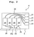
- Fig. 2 schematically shows a side view illustrating an arrangement of the sub printer 4, which depicts an internal structure as viewed when one side surface of the casing 5 is removed.
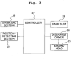
- Fig. 3 shows a block diagram illustrating the function of the sub printer 4 shown in Fig. 2 .
- the sub printer 4 has the rectangular parallelepiped-shaped casing 5 and four second ink tanks 20 each having a small volume (for example, 1 cc) provided in the casing 5.
- the second ink tanks 20 correspond to the four color inks described above.
- Four subsidiary-side connecting sections 21, which make communication between the second ink tanks 20 and the first ink tanks 12 installed to the main printer 2, are provided on one side wall of the casing 5.
- the subsidiary-side connecting sections 21 correspond to the four second ink tanks 20.
- the subsidiary-side connecting sections 21 are connected to the second ink tanks 20 one to one via tubes 22.
- a second head 23 (see Fig. 3 ) having a nozzle surface 23a and a head cover 24 to openably/closably cover the nozzle surface 23a of the second head 23 are provided on another side wall of the casing 5.
- the nozzle surface 23a is provided so that the nozzle surface 23a is exposed to the outside of the second head 23.
- the head cover 24 is closed (as shown by broken lines in Fig. 2 )
- the nozzle surface 23a is covered with the head cover 24 substantially hermetically.
- the head cover 24 is opened (as shown by solid lines in Fig. 2 )
- the nozzle surface 23a is exposed to the outside of the second head 23.
- the second ink tanks 20 of the respective colors are connected to the second head 23 via tubes 25. The inks, which are supplied from the second ink tanks 20, are discharged to the outside.
- the sub printer 4 includes a discharge driver 26 for driving the second head 23.
- the discharge driver 26 is connected to a controller 27.
- the controller 27 is composed of, for example, an IC chip, RAM, and ROM, which is operable in accordance with a program recorded in ROM.
- the sub printer 4 is provided with a card slot 28 which is connected to the controller 27, an operating section 29, and a position-detecting section 30.
- Various types of small-sized memory cards as storage media can be installed to the card slot 28.
- the image data which is stored in the small-sized memory card installed to the card slot 28, can be read by performing the predetermined operation with the operating section 29.
- the read image data is once stored in RAM possessed by the controller 27.
- the second head 23 discharges the inks in accordance with the instruction supplied from the controller 27, and thus the image represented by the image data can be formed on the recording medium.
- the sub printer 4 is provided with a roller or rollers (not shown) for maintaining a constant distance from the recording paper, for example, when the manual scanning is performed on the recording paper.
- the position-detecting section 30 is capable of detecting the position of the sub printer 4 in accordance with the angle of rotation of the roller.
- the controller 27 controls the ink discharge from the second head 23 on the basis of the information in relation to the position inputted from the position-detecting section 30.
- the sub printer 4 can receive the ink supplied to the second ink tank 20 of the sub printer 4 from the first tank 12 installed to the main printer 2 when the sub printer 4 is installed to the main printer 2. An explanation will be made below in respective embodiments about forms of connection brought about when the sub printer 4 is installed to the main printer 2.
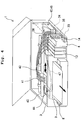
- Fig. 4 schematically shows a perspective view illustrating an internal arrangement of the main printer 2 to which the sub printer 4 as described above is installed.
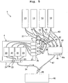
- Fig. 5 schematically shows the printer system 1, which depicts a form of connection according to a first embodiment when the sub printer 4 is installed to the main printer 2.
- a guide rod 40 which extends in the left-right direction, is provided in the casing 3 of the main printer 2.
- a first head 41 (see Fig. 5 ) is supported by the guide rod 40 so that the first head 41 is capable of being subjected to the scanning in the left-right direction.
- Four tubes 42 which correspond to the respective colors of the inks, are provided to extend from the first head 41.
- the tubes 42 are connected to the tank-installing section 12 respectively.
- first valves (first regulating sections) 43 which regulate the flow of the inks, are provided for the tubes 42 respectively.
- the respective first valves 43 are operable independently from each other.
- the first ink tanks 13 and the first head 41 are communicated with each other via the tubes 42 in a state in which the first valves 43 are opened. Therefore, the inks of the respective colors can be independently supplied from the first ink tanks 13 to the first head 41. On the other hand, the inks are not allowed to flow via the tubes 42 between the first ink tanks 13 and the first head 41 in a state in which the first valves 43 are closed, because the closing is effected between the first ink tanks 13 and the first head 41.
- a first cap (cap for the first head) 44 which hermetically seals the nozzle surface 41a of the first head 41 (see Fig. 5 ) from the lower portion, is provided in the casing 3 of the main printer 2.
- the first cap 44 is provided at the position at which the first cap 44 is opposed to the nozzle surface (ink discharge surface) 41a when the first head 41 is positioned at one end in the scanning range.
- the first cap 44 is provided opposingly to the left end of the scanning range of the first head 41.
- a pump 45 and a waste ink-accommodating section 46 are provided at the back of the tank-installing section 12 at the right end in the casing 3.
- the waste ink-accommodating section 46 has an unillustrated case and an ink-absorbing member such as sponge accommodated in the case. As shown in Fig. 5 , the waste ink-accommodating section 46 is communicated with the first cap 44 via a tube (communication passage) 47.
- the pump 45 is capable of sucking the fluid via the tube 47.
- a second cap 33 is arranged in the vicinity of the lower portion of the sub printer-installing port 14 in the casing 3.
- the second cap 33 hermetically seals the nozzle surface (ink discharge surface) 23a of the second head 23 of the sub printer 4 from the lower position when the sub printer 4 is installed to the sub printer-installing port 14.
- the second cap 33 is connected to the waste ink-accommodating section 46 via a tube (communication passage) 34.
- the fluid, which is contained in the tube 34, is also sucked by the pump 45 described above.
- Main-side connecting sections 35 are provided in the sub printer-installing port 14 in the main printer 2.
- the main-side connecting sections 35 are connected to the subsidiary-side connecting sections 21 (see Fig. 5 ).
- Tubes 36 are allowed to extend from the main-side connecting sections 35. Forward ends of the tubes 36 are connected to the first ink tanks 13 installed to the tank-installing section 12.
- Second valves (second regulating sections) 37 which regulate the flow of the inks in the tubes 36, are provided at intermediate positions of the tubes 36 which are allowed to extend from the main-side connecting sections 35 to the first ink tanks 13.
- the respective second valves 37 are operable independently from each other.
- Fig. 6 shows a block diagram illustrating the function of the main printer 2 described above.
- the main printer 2 is provided with a controller 50.
- the operation panel 11 is connected to the controller 50.
- the first head 41 is connected to the controller 50 via a discharge driver 51.
- the main printer 2 further comprises a carriage motor 52 which moves the first head 41 in the scanning direction, and a scanning driver 53 which drives the carriage motor 52.
- the carriage motor 52 is connected to the controller 50 via the scanning driver 53. Therefore, when the user operates the operation panel 11, the controller 50 outputs control signals to the discharge driver 51 and the scanning driver 53 respectively.
- the scanning driver 53 moves the first head 41 by a predetermined distance in the scanning direction on the basis of the control signal.
- the discharge driver 51 allows the head 41 to discharge the inks on the basis of the control signal.
- the pump 45 described above is connected to the controller 50 via a pump driver 54. Further, the valves 37, 43 are connected to the controller 50 via a valve driver 55.
- the pump driver 54 and the valve driver 55 output driving signals on the basis of control signals supplied from the controller 50 to drive the pump 45 and the valves 37, 43 in accordance with the driving signals.
- a sub printer-detecting section 56 and a residual amount-detecting section 57 are connected to the controller 50.
- the sub printer-detecting section 56 detects whether or not the sub printer 4 is connected to the main printer 2, in particular whether or not the sub printer 4 is installed to the sub printer-installing port 14 to connect the sub printer side connecting sections 21 with respect to the main printer side connecting sections 35. The information thereof is outputted to the controller 50.
- the residual amount-detecting section 57 detects the ink residual amount in the second ink tank 20 of each of the colors possessed by the sub printer 4 when the sub printer 4 is installed to the main printer 2. The information thereof is outputted to the controller 50.
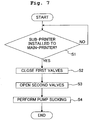
- Fig. 7 shows a flow chart illustrating the operation of the main printer 2 when the inks are supplied from the main printer 2 to the sub printer 4 by using the trigger of the installation of the sub printer 4 in the printer system 1.
- the controller 50 of the main printer 2 judges whether or not the sub printer 4 is installed to the main printer 2 on the basis of the signal supplied from the sub printer-detecting section 56 (S1). If it is judged that the sub printer 4 is not installed (S1: NO), the operation of Step 1 is repeated. If it is judged that the sub printer 4 is installed (S1: YES), the routine proceeds to the next step.
- Fig. 5 when the sub printer 4 is installed to the main printer 2, the both are connected to one another by means of the main printer side connecting sections 35 and the sub printer side connecting sections 21. The head cover 24 of the sub printer 4 is opened, and the exposed nozzle surface 23a of the second head 23 is hermetically sealed by the second cap 33.
- Step 1 If it is judged in Step 1 that the sub printer 4 is installed to the main printer 2, then the ink flow is regulated between the first ink tanks 13 and the first head 41 by closing the first valves 43 (S2), and the second valves 37 are opened (S3). Accordingly, the first ink tanks 13 of the main printer 2 and the second ink tanks 20 of the sub printer 4 are communicated with each other via the main printer-side connecting sections 35 and the sub printer side-connecting sections 21. Subsequently, the pump 45 is driven by the controller 50 to effect the sucking (S4). Accordingly, the inks are supplied from the first ink tanks 13 to the second ink tanks 20. The first valves 43 are closed during the ink supply. Therefore, the inks are not allowed to flow from the first ink tanks 13 to the first head 41.
- the printer system 1 When the printer system 1 is operated as described above, the user does not especially worry about the ink residual amounts in the second ink tanks 20 of the sub printer 4, and the inks can be supplied from the main printer 2 to the sub printer 4 merely by installing the sub printer 4 to the main printer 2 when the sub printer 4 is not used.
- Fig. 8 shows a flow chart illustrating the operation of the main printer 2 when the inks are supplied depending on the ink residual amounts in the second ink tanks 20 by using the trigger of the installation of the sub printer 4 to the main printer 2 in the printer system 1.
- the controller 50 of the main printer 2 judges whether or not the sub printer 4 is installed to the main printer 2 on the basis of the signal supplied from the sub printer-detecting section 56 (S11). If it is judged by the controller 50 that the sub printer 4 is not installed (S11: NO), the operation of Step 11 is repeated. If it is judged that the sub printer 4 is installed (S11: YES), the residual amount-detecting section 57 (see Fig. 6 ) is controlled to detect the ink residual amounts of the second ink tanks 20 possessed by the sub printer 4 (S12).
- the controller 50 determines whether the ink residual amounts in the second ink tanks 20 are not more than a predetermined value on the basis of the signal supplied from the residual amount-detecting section 57 (S13).
- the predetermined value may be zero value at which the ink is not present at all in the second ink tank 20. If necessary, the predetermined value may be set to an arbitrary value. If it is judged in Step 13 that the ink residual amount is larger than the predetermined value (S13: NO), the ink supply operation is completed without supplying the ink to the second ink tank.
- Step 13 if it is judged in Step 13 that the ink residual amount is not more than the predetermined value (S13: YES), the operation is performed in the same manner as in Steps 2 to 4 shown in Fig. 7 . That is, the first valves 43 are closed (S14), the second valves 37 are opened (S15), and the pump 45 is finally driven to effect the sucking (S16) so that the inks are supplied from the first ink tanks 13 to the second ink tanks 20.
- the inks can be appropriately supplied depending on the degree of decrease of the ink residual amount in the second ink tank 20.
- the residual amount-detecting section 57 is constructed so that the residual amount-detecting section 57 is capable of individually detecting the ink residual amounts of the four second ink tanks 20 provided for the sub printer 4
- the ink may be supplied to only the second ink tank 20 in which the ink residual amount is not more than the predetermined value.
- the second valve 37 which is arranged for the tube 36 to connect the second ink tank 20 to which the ink is intended to be supplied and the first ink tank 13, is opened.
- the other second valves 37 and all of the first valves 43 are closed.
- the pump 45 is driven to effect the sucking. Accordingly, the ink is supplied to only the objective second ink tank 20.
- Fig. 9 shows a flow chart illustrating the operation of the main printer 2 when the inks are supplied on the basis of the operation of the operation panel 11 by the user after installing the sub printer 4 in the printer system 1.
- the controller 50 of the main printer 2 judges whether or not the sub printer 4 is installed to the main printer 2 on the basis of the signal supplied from the sub printer-detecting section 56 (S21). If it is judged that the sub printer 4 is not installed (S21: NO), the operation in Step 21 is repeated. If it is judged that the sub printer 4 is installed (S21: YES), it is subsequently judged by the controller 50 whether or not the operation panel 11 is operated by the user and the signal to execute the ink supply operation is outputted from the operation panel 11 (S22).
- Step 22 If it is judged by the controller 50 that the signal of the execution is not outputted from the operation panel 11 (S22: NO), the operation in Step 22 is repeated. If it is judged that the signal is outputted (S22: YES), the operation is thereafter performed in the same manner as in Steps 2 to 4 as having been already explained. That is, the first valves 43 are closed (S23), the second valves 37 are opened (S24), and the pump 45 is finally driven to effect the sucking (S25) so that the inks are supplied from the first ink tanks 13 to the second ink tanks 20.
- the inks can be supplied to the sub printer 4 at the timing determined by the user. Therefore, for example, even when the sub printer 4 is installed to the main printer 2 during which the inks are discharged from the first head 41 of the main printer 2 to form the image on the recording paper, then the printing by the main printer 2 is not interrupted, and the inks are not supplied to the sub printer 4.
- the inks can be supplied to the sub printer 4 at the timing desired by the user after the completion of the printing by the main printer 2.
- the timing, at which the ink supply to the sub printer 4 is completed, may be set arbitrarily.
- the ink may be supplied from the first ink tank 13 to the second ink tank 20 until the second ink tank 20 is fully filled.
- the ink may be supplied from the first ink tank 13 to the second ink tank 20 until the ink amount in the second ink tank 20 arrives at a predetermined amount.
- the ink supply operation may be completed at a point of time at which the detection is effected as well. Further alternatively, the user may set the ink supply amount by operating the operation panel 11.
- the pump 45 which is provided for the main printer 2, can be also used as a pump to purge the first head 41. Further, the pump 45 can be also used as a pump to purge the second head 23 of the sub printer 4 when the sub printer 4 is installed to the main printer 2.
- the single pump 45 can be used to execute the ink supply to the second ink tanks 20, the purge for the first head 41, and the purge for the second head 20. Therefore, it is unnecessary to prepare individual pumps depending on the respective processes. It is possible to realize the small size and the low price of the main printer 2 and the sub printer 4. Further, it is possible to realize the large volumes of the second ink tanks 20, because the sub printer 4 is not provided with any pump.
- the first and second valves 43, 37, the pump 45, the main-side connecting section (first connecting section), and the controller 50 correspond to the first supply mechanism
- the subsidiary-side connecting section (second connecting section) 21 corresponds to the second supply mechanism
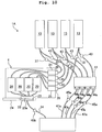
- Fig. 10 schematically shows a printer system 1A, which depicts a form of connection according to a second embodiment when a sub printer 4 is installed to a main printer 2.
- the printer system 1A includes four first caps 44 which cover the nozzle surface 41a of the first head 41 individually for respective colors, tubes 47a which are provided to extend from the first caps 44 to the waste ink-accommodating section 46 respectively, and pumps 45a which are provided at intermediate positions of the tubes 47a respectively to suck the internal fluids contained in the tubes 47a. Further, an individual pump 45b is provided for the tube 34 which extends from the second cap 33.
- the other parts or components are constructed in the same manner as those of the printer system 1. Therefore, the corresponding parts or components are designated by the same reference numerals.
- the purge process can be executed for the first head 41 for each of the colors.
- the pump 45b is provided, which is exclusively used for the ink supply to the sub printer 4. Therefore, any pump, which has the specification suitable for the ink supply process to the sub printer 4, can be adopted as the pump 45b.
- the printer system 1A is capable of supplying the inks to the sub printer 4 in the same manner as in the printer system 1. The operation, the function, and the effect of the printer system 1A are the same as those having been already explained with reference to Figs. 7 to 9 .
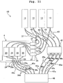
- Fig. 11 schematically shows a printer system 1B according to a third embodiment.
- the printer system 1B shown in Fig. 11 is different from the printer system 1A (see Fig. 10 ) in the form of connection between the sub printer 4 and the waste ink-accommodating section 46.
- the printer system 1B includes individual second caps 33a which hermetically seal the nozzle surface 23a of the second head 23 of the sub printer 4 for the respective colors, tubes 34a which extend from the second caps 33a respectively to the waste ink-accommodating section 46, and pumps 45c which are provided at intermediate positions of the tubes 34a respectively to suck the internal fluids contained in the tubes 34a.
- the other parts or components are constructed in the same manner as those of the printer system 1A shown in Fig. 10 . Therefore, the corresponding parts or components are designated by the same reference numerals.
- the ink can be selectively supplied for each of the colors to each of the second ink tanks 20 of the sub printer 4. For example, even when the ink residual amount in one ink tank 20 of the four ink tanks 20 is decreased, it is possible to supply only the ink of the one color.
- the ink of the selected color When the ink of the selected color is supplied, it is possible to decrease the number of valves of the first valves 43 and the second valves 37 to be driven.
- the following procedure is available. That is, only one second valve 37 corresponding to this color, which is included in the four second valves 37 for regulating the ink flow and which is arranged between the first ink tanks 13 and the second ink tanks 20, is opened. Only one first valve 43 corresponding to this color, which is included in the four first valves 43 for regulating the ink flow and which is arranged between the first ink tanks 13 and the first head 41, is closed. Further, the pump 45c corresponding to this color is driven to effect the sucking. As described above, it is enough to drive the two valves and the one pump 45c which are included in the large number of the provided valves 37, 43 and the large number of the provided pumps 45a, 45c.
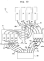
- Fig. 12 schematically shows a printer system 1C according to a fourth embodiment.
- the printer system 1C shown in Fig. 12 is different from the printer system 1B (see Fig. 11 ) in that the pumps 45c provided between the second caps 33 and the waste ink-accommodating section 46 are removed, and pumps 45d are provided in place of the second valves 37 provided between the first ink tanks 13 and the second ink tanks 20.
- the other parts or components are constructed in the same manner as the printer system 1B. Therefore, the corresponding parts or components are designated by the same reference numerals.
- the printer system 1C it is unnecessary to provide the second valves 37 provided in the printer systems 1, 1A, 1B in the passages ranging from the first ink tanks 13 via the second ink tanks 20 to arrive at the waste ink-accommodating section 46.
- Any arbitrary ink can be also selectively supplied to the sub printer 4 by means of the printer system 1C in the same manner as in the printer system 1B described above. Further, it is possible to decrease the number of the first valve or valves 43 to be driven when the ink supply is performed.
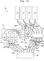
- Fig. 13 schematically shows a printer system 1D according to a fifth embodiment.
- the printer system 1D shown in Fig. 13 is different from the printer system 1C shown in Fig. 12 in that the first valves 43, which are provided between the first ink tanks 13 and the first head 41 in the printer system 1C, are removed, and first valves 43a are provided between the first caps 44a and the pump 45a at intermediate positions of the tubes 47a to make communication between the first caps 44a and the waste ink-accommodating section 46.
- the other parts or components of the printer system 1D are constructed in the same manner as those of the printer system 1C, any explanation of which will be omitted, while the corresponding parts or components are designated by the same reference numerals.
- Any ink can be also selectively supplied to the sub printer 4 by means of the printer system 1D in the same manner as in the printer system 1C described above. Further, it is possible to decrease the number of the first valve or valves 43 to be driven when the ink supply is performed.
- Fig. 14 schematically shows a printer system 1E according to a sixth embodiment.
- the printer system 1E shown in Fig. 14 is different from the printer system 1D (see Fig. 13 ) in that the pumps 45d, which are provided between the first ink tanks 13 and the second ink tanks 20 in the printer system 1D, are removed, and pumps 45e are provided at intermediate positions of the tubes 34a to make communication between the second caps 33a and the waste ink-accommodating section 46.
- the other parts or components of the printer system 1E are constructed in the same manner as those of the printer system 1D, any explanation of which will be omitted, while the corresponding parts or components are designated by the same reference numerals.
- Any ink can be also selectively supplied to the sub printer 4 by means of the printer system 1E in the same manner as in the printer system 1D described above. Further, it is possible to decrease the number of the first valve or valves 43 to be driven when the ink supply is performed.
- Fig. 15 schematically shows a printer system 1F according to a seventh embodiment.
- the printer system 1F shown in Fig. 15 is different from the printer system 1B shown in Fig. 11 in that valves 143 are provided in place of the pumps 45c at intermediate positions of the tubes 34a allowed to extend from the second caps 33a, the tubes 34a merge into one tube 134 at the downstream of the valves 143, and a pump 145 for sucking the fluid is provided in the tube 134.
- the inks of the respective colors can be selectively supplied to the second ink tanks 20 of the sub printer 4, and the second head 23 of the sub printer 4 can be selectively purged for the respective colors, in the same manner as in the printer system 1B.
- valves are provided in place of the pumps 45a at intermediate positions of the tubes 47a allowed to extend from the first cap 44a, the tubes 47a are allowed to merge into one tube at the downstream, and a pump is provided for the merged tube.
- the ink can be supplied to the sub printer 4 by installing the sub printer 4 to the main printer 2 having the printer function. That is, the main printer 2 can form the image on the recording paper by discharging the inks from the first head 41, because the main printer 2 has the printer function, while the main printer 2 can also supply the inks to the sub printer 4.
- the main printer 2 is provided with both of the printer function and the ink supply function to supply the inks to the sub printer 4. Therefore, it is unnecessary to prepare any exclusive station specialized to supply the inks to the sub printer 4.
- the sub printer 4 is installed to the sub printer-installing port 14 of the main printer 2.
- the form of installation of the sub printer 4 to the main printer 2 is not limited thereto.
- the sub printer 4 may be installed to the main printer 2 such that a main printer side connecting section 35 is provided at the forward end of a tube provided to extend from the main printer 2, and the sub printer side connecting section 21 is connected thereto.
- the first ink tank 13 and the second ink tank 20 may be communicated with each other via the tube provided to extend from the main printer 2 so that the inks may be supplied.
- the pumps 45, 45a to 45e are provided at the intermediate positions of the respective tube, which may be provided, for example, at the ends of the respective tubes.
- the pressurizing type pump may be operated in place of the pump sucking operation (S4, S16, S25) shown in Figs. 7 to 9 .
- the main printer is not necessarily the multifunction machine having, for example, the scan function.
- the main printer may have only the printer function.
- the number and the type of the ink or inks of each of the main printer and the sub printer may be arbitrary.
- the main printer may be a full color printer for discharging the four color inks of black, cyan, magenta, and yellow
- the sub printer may be a monochrome or black and white printer for discharging only the black ink.
- only the black ink is supplied when the sub printer is installed to the main printer.
- the sub printer may be of the charging type.
- the sub printer may be charged by receiving the supply of the electric power from the main printer during the period in which the sub printer is installed to the main printer.
- the present invention is applicable to the printer system for which any exclusive station is not provided while the portable type printer is of the ink supplement type, wherein the printer system does not cause such a situation that there is no way of use except for the ink supplement and any excessive installation space is required.
Landscapes
- Ink Jet (AREA)
Claims (13)
- Druckersystem (1), das ein Drucken durch Abgeben einer Tinte auf ein Aufzeichnungsmedium durchführt, wobei das Druckersystem aufweist:einen Hauptdrucker (2), der aufweist: einen ersten Tank (13), in dem die Tinte gespeichert ist; und einen ersten Kopf (41), der die Tinte, die vom ersten Tank (13) geliefert wird, auf das Aufzeichnungsmedium abgibt; undeinen Hilfsdrucker (4) der tragbaren Art, wobei der Hilfsdrucker (4) aufweist: einen zweiten Tank (20), in dem die Tinte gespeichert ist, wobei das Volumen des zweiten Tanks (20) kleiner ist als das des ersten Tanks (13), und einen zweiten Kopf (23), der die Tinte, die vom zweiten Tank (20) geliefert wird, auf ein Aufzeichnungsmedium abgibt,dadurch gekennzeichnet, dass der Hauptdrucker (2) einen ersten Installierabschnitt (14) aufweist, der dafür ausgelegt ist, den Hilfsdrucker (4) lösbar aufzunehmen,
der Hauptdrucker (2) einen ersten Liefermechanismus (35, 36, 37, 42, 43) aufweist, einschließlich eines ersten Verbindungsabschnitts (35, 36), der mit dem ersten Tank (13) in Verbindung steht,
der Hilfsdrucker (4) einen zweiten Liefermechanismus aufweist, einschließlich eines zweiten Verbindungsabschnitts (21), der mit dem zweiten Tank (20) in Verbindung steht,
der erste Verbindungsabschnitt (35, 36) und der zweite Verbindungsabschnitt (21) so gestaltet sind, dass sie miteinander zu verbinden sind, um eine Verbindung zwischen dem ersten Tank (13) und dem zweiten Tank (20) herzustellen, wenn der Hilfsdrucker (4) am Hauptdrucker (2) installiert wird. - Druckersystem nach Anspruch 1, wobei der erste Liefermechanismus (35, 36, 37, 42, 43) einen ersten Regulierungsabschnitt (42, 43) aufweist, um einen Tintenstrom zwischen dem ersten Tank (13) und dem ersten Kopf (41) zu regulieren, und dafür ausgelegt ist, den Tintenstrom zwischen dem ersten Tank (13) und dem ersten Kopf (41) zu unterbrechen, wenn die Tinte vom ersten Tank (13) zum zweiten Tank (20) geliefert wird.
- Druckersystem nach Anspruch 1, wobei
der erste Liefermechanismus (35, 36, 37, 42, 43) aufweist: einen ersten Regulierungsabschnitt (43), der dafür ausgelegt ist, einen Tintenstrom zwischen dem ersten Tank (13) und dem ersten Kopf (41) zu regulieren, und einen zweiten Regulierungsabschnitt (37), der dafür ausgelegt ist, einen Tintenstrom zwischen dem ersten Tank (13) und dem ersten Verbindungsabschnitt (35, 36) zu regulieren;
und
der erste Regulierungsabschnitt (43) und der zweite Regulierungsabschnitt (37) unabhängig voneinander betätigbar sind. - Druckersystem nach Anspruch 3, wobei der erste und der zweite Liefermechanismus (21, 35, 36, 37, 42, 43) die Tinte vom ersten Tank (13) zum zweiten Tank (20) liefern, wenn der erste Verbindungsabschnitt (35, 36) und der zweite Verbindungsabschnitt (21) miteinander verbunden sind.
- Druckersystem nach Anspruch 4, wobei der erste und der zweite Liefermechanismus die Tinte vom ersten Tank (13) zum zweiten Tank (20) liefern, wenn eine Restmenge der Tinte, die im zweiten Tank (20) des Hilfsdruckers (4) enthalten ist, nicht mehr als ein vorgegebener Wert ist.
- Druckersystem nach Anspruch 4, ferner aufweisend: eine Eingabevorrichtung, die einen vorgegebenen Befehl eingibt, wobei der erste und der zweite Liefermechanismus die Tinte vom ersten Tank (13) zum zweiten Tank (20) liefern, wenn über die Eingabevorrichtung ein Befehl zur Ausführung einer Tintenlieferung zum zweiten (20) Tank des Hilfsdruckers (4) eingegeben wird.
- Druckersystem nach Anspruch 1, wobei der erste Liefermechanismus eine Pumpe (45) aufweist, die so gestaltet ist, dass sie die Tinte, die im ersten Tank (13) enthalten ist, zum ersten Kopf (41) liefert, und die so gestaltet ist, dass sie die Tinte vom ersten Tank (13) zum zweiten Tank (20) liefert.
- Druckersystem nach einem der Ansprüche 1 bis 7, wobei der Hauptdrucker (2) ein Gehäuse (3), in dem der erste Kopf (41) aufgenommen ist, und einen zweiten Installierabschnitt (12), in dem der erste Tank (13) lösbar aufgenommen ist, aufweist, wobei der erste Installierabschnitt (12) und der zweite Installierabschnitt (14) angrenzend an ein und dieselbe Wandoberfläche (3a) des Gehäuses (3) angeordnet sind.
- Druckersystem nach Anspruch 8, wobei der erste und der zweite Liefermechanismus aufweisen: einen Erfassungsmechanismus, der eine Installation des Hilfsdruckers (4) am zweiten Installierabschnitt (14) erfasst, und einen Tintenmengenerfassungsmechanismus, der eine Tintenmenge erfasst, die im zweiten Tank (20) des Hilfsdruckers (4) enthalten ist.
- Druckersystem nach einem der Ansprüche 1 bis 9, wobei der Hilfsdrucker ferner aufweist: eine Walze, die einen konstanten Abstand zwischen dem zweiten Kopf (23) und einem Aufzeichnungsmedium aufrechterhält, einen Positionserfassungsabschnitt, der eine Position des Hilfsdruckers auf Basis eines Drehwinkels der Walze erfasst, und einen Steuermechanismus, der mit dem Positionserfassungsabschnitt verbunden ist und der eine Abgabe der Tinte vom zweiten Kopf (23) steuert.
- Verfahren zum Liefern einer Tinte für ein Druckersystem (1) nach Anspruch 1, wobei der erste Liefermechanismus aufweist: ein erstes Ventil, das einen Tintenstrom zwischen dem ersten Tank (13) und dem ersten Kopf (41) reguliert, ein zweites Ventil, das einen Tintenstrom zwischen dem ersten Tank (13) und dem zweiten Tank (20) reguliert, und eine Pumpe (45), welche die Tinte vom ersten Tank (13) zum zweiten Tank (20) liefert, und wobei das Verfahren umfasst:Erfassen einer Installation des Hilfsdruckers (4) am Hauptdrucker (2);Schließen des ersten Ventils und Öffnen des zweiten Ventils, wenn die Installation des Hilfsdruckers (4) erfasst wird; undAntreiben der Pumpe, um die Tinte vom ersten Tank (13) zum zweiten Tank (20) zu liefern.
- Verfahren zum Liefern von Tinte nach Anspruch 11, ferner das Erfassen einer Menge der Tinte, die im zweiten Tank (20) enthalten ist, umfassend, wobei das erste Ventil geschlossen wird und das zweite Ventil geöffnet wird, wenn die Installation des Hilfsdruckers (4) erfasst wird und die Menge der Tinte, die im zweiten Tank (20) enthalten ist, nicht mehr ist als eine vorgegebene Menge.
- Verfahren zum Liefern von Tinte nach Anspruch 11, wobei das Druckersystem (1) ferner eine Eingabevorrichtung aufweist, die einen vorgegebenen Befehl eingibt, und das Verfahren ferner das Schließen des ersten Ventils und das Öffnen des zweiten Ventils umfasst, wenn die Installation des Hilfsdruckers (4) erfasst wird und über die Eingabevorrichtung ein Befehl zur Ausführung einer Lieferung von Tinte zum zweiten Tank (20) eingegeben wird.
Applications Claiming Priority (1)
| Application Number | Priority Date | Filing Date | Title |
|---|---|---|---|
| JP2007071166A JP2008229974A (ja) | 2007-03-19 | 2007-03-19 | プリンタシステム、並びにこれに用いられる親機プリンタ及び子機プリンタ |
Publications (4)
| Publication Number | Publication Date |
|---|---|
| EP1972452A2 EP1972452A2 (de) | 2008-09-24 |
| EP1972452A3 EP1972452A3 (de) | 2009-05-06 |
| EP1972452B1 true EP1972452B1 (de) | 2019-01-09 |
| EP1972452B8 EP1972452B8 (de) | 2019-03-06 |
Family
ID=39580162
Family Applications (1)
| Application Number | Title | Priority Date | Filing Date |
|---|---|---|---|
| EP08004784.8A Ceased EP1972452B8 (de) | 2007-03-19 | 2008-03-14 | Druckersystem sowie Verfahren zur Versorgung mit Tinte |
Country Status (4)
| Country | Link |
|---|---|
| US (1) | US8025373B2 (de) |
| EP (1) | EP1972452B8 (de) |
| JP (1) | JP2008229974A (de) |
| CN (1) | CN101269586B (de) |
Families Citing this family (5)
| Publication number | Priority date | Publication date | Assignee | Title |
|---|---|---|---|---|
| JP6161869B2 (ja) * | 2012-03-05 | 2017-07-12 | セイコーエプソン株式会社 | 液体噴射装置 |
| JP6064687B2 (ja) * | 2013-03-07 | 2017-01-25 | セイコーエプソン株式会社 | 画像形成システム |
| US9761284B1 (en) * | 2016-06-30 | 2017-09-12 | Intel Corporation | Current starved voltage comparator and selector |
| EP3820703B1 (de) | 2018-07-13 | 2024-01-10 | Hewlett-Packard Development Company, L.P. | Reservoirs für drucksubstanz |
| JP7077866B2 (ja) * | 2018-08-27 | 2022-05-31 | セイコーエプソン株式会社 | 液体噴射装置 |
Family Cites Families (12)
| Publication number | Priority date | Publication date | Assignee | Title |
|---|---|---|---|---|
| JPH0958060A (ja) | 1995-08-23 | 1997-03-04 | Brother Ind Ltd | ペン入力による印字装置 |
| JP3329174B2 (ja) * | 1996-02-29 | 2002-09-30 | セイコーエプソン株式会社 | 多機能型印刷装置 |
| JPH09300718A (ja) * | 1996-05-17 | 1997-11-25 | Brother Ind Ltd | 手動型印字装置 |
| JPH09300782A (ja) * | 1996-05-20 | 1997-11-25 | Canon Inc | ホストプリンタ並びにハンディプリンタ並びにプリンタシステムおよびプリンタシステムの印刷制御方法 |
| JP3530738B2 (ja) | 1998-04-15 | 2004-05-24 | キヤノン株式会社 | 給紙装置及びこれを備えた画像形成装置 |
| US6200043B1 (en) | 1998-04-15 | 2001-03-13 | Canon Kabushiki Kaisha | Sheet feeding apparatus and image forming apparatus having such sheet feeding apparatus |
| US6478398B2 (en) * | 2001-01-08 | 2002-11-12 | Xerox Corporation | Ink jet printer having a printhead assembly for recording high quality graphic images and photo quality images |
| JP2002361934A (ja) | 2001-06-07 | 2002-12-18 | Matsushita Electric Ind Co Ltd | ハンディプリンタ |
| US6769766B2 (en) * | 2001-12-28 | 2004-08-03 | Konica Corporation | Inkjet printer utilizing white ink |
| JP2005028675A (ja) * | 2003-07-10 | 2005-02-03 | Fuji Xerox Co Ltd | インク供給装置及び記録装置 |
| TW200509666A (en) * | 2003-08-27 | 2005-03-01 | Avision Inc | Scanning copier with multiple selectable printers |
| JP2008229976A (ja) * | 2007-03-19 | 2008-10-02 | Brother Ind Ltd | プリンタシステム、及びこれに用いられる親機プリンタ |
-
2007
- 2007-03-19 JP JP2007071166A patent/JP2008229974A/ja active Pending
-
2008
- 2008-03-14 EP EP08004784.8A patent/EP1972452B8/de not_active Ceased
- 2008-03-18 US US12/050,884 patent/US8025373B2/en not_active Expired - Fee Related
- 2008-03-19 CN CN2008100871153A patent/CN101269586B/zh not_active Expired - Fee Related
Non-Patent Citations (1)
| Title |
|---|
| None * |
Also Published As
| Publication number | Publication date |
|---|---|
| CN101269586B (zh) | 2010-06-16 |
| US8025373B2 (en) | 2011-09-27 |
| JP2008229974A (ja) | 2008-10-02 |
| CN101269586A (zh) | 2008-09-24 |
| EP1972452A3 (de) | 2009-05-06 |
| EP1972452A2 (de) | 2008-09-24 |
| EP1972452B8 (de) | 2019-03-06 |
| US20080231674A1 (en) | 2008-09-25 |
Similar Documents
| Publication | Publication Date | Title |
|---|---|---|
| CN115056577B (zh) | 打印装置 | |
| US6783215B2 (en) | Ink container, inkjet printing apparatus, and ink supplying method | |
| US9561658B2 (en) | Printing apparatus and control method | |
| JP5067876B2 (ja) | インクジェット記録装置 | |
| US20030007045A1 (en) | Ink container, inkjet printing apparatus, and ink supplying method | |
| EP1972452B1 (de) | Druckersystem sowie Verfahren zur Versorgung mit Tinte | |
| EP3718772A1 (de) | Tintenstrahldruckvorrichtung und tintentank | |
| US8186800B2 (en) | Printer system, main printer to be used therefor, and method for discharging waste ink | |
| US11117380B2 (en) | Liquid ejection apparatus and method of controlling liquid ejection apparatus | |
| JP2008238787A (ja) | 液体供給システム、液体供給装置、および液体供給方法 | |
| JP2007152725A (ja) | インクジェットプリンタの回復装置 | |
| US6471345B2 (en) | Inks-and-printing-media-integral-type pack, printing liquid and sheets container, sheet supplying device, and printing apparatus comprising the same | |
| JP3394864B2 (ja) | インクカートリッジおよびインクジェット記録装置 | |
| US7878608B2 (en) | Liquid discharge apparatus and maintenance method for liquid discharge apparatus | |
| US7465043B2 (en) | Liquid distribution unit, ink-jet recording apparatus and image forming apparatus | |
| US20190217621A1 (en) | Inkjet recording apparatus capable of smoothly supplying ink to first damper chamber and second damper chamber | |
| JP4337330B2 (ja) | インクジェット記録装置 | |
| JP2001063086A (ja) | インクジェット記録装置 | |
| JP2001212986A (ja) | インク−被記録媒体一体型のパック、および記録装置 | |
| JP3595753B2 (ja) | 記録用液体・シート内蔵容器、および、シート供給装置 | |
| JP4929638B2 (ja) | インクジェット記録装置 | |
| US20080158272A1 (en) | Recording apparatus and recording method | |
| JP2023033647A (ja) | 記録装置 | |
| JP2001212987A (ja) | インク移送システム、インク交換方法、及びインクジェット記録装置 | |
| JPH05162297A (ja) | インクジェット記録装置 |
Legal Events
| Date | Code | Title | Description |
|---|---|---|---|
| PUAI | Public reference made under article 153(3) epc to a published international application that has entered the european phase |
Free format text: ORIGINAL CODE: 0009012 |
|
| AK | Designated contracting states |
Kind code of ref document: A2 Designated state(s): AT BE BG CH CY CZ DE DK EE ES FI FR GB GR HR HU IE IS IT LI LT LU LV MC MT NL NO PL PT RO SE SI SK TR |
|
| AX | Request for extension of the european patent |
Extension state: AL BA MK RS |
|
| PUAL | Search report despatched |
Free format text: ORIGINAL CODE: 0009013 |
|
| AK | Designated contracting states |
Kind code of ref document: A3 Designated state(s): AT BE BG CH CY CZ DE DK EE ES FI FR GB GR HR HU IE IS IT LI LT LU LV MC MT NL NO PL PT RO SE SI SK TR |
|
| AX | Request for extension of the european patent |
Extension state: AL BA MK RS |
|
| RIC1 | Information provided on ipc code assigned before grant |
Ipc: B41J 2/175 20060101AFI20080820BHEP Ipc: B41J 3/36 20060101ALI20090327BHEP Ipc: B41J 3/42 20060101ALI20090327BHEP |
|
| 17P | Request for examination filed |
Effective date: 20091021 |
|
| AKX | Designation fees paid |
Designated state(s): DE FR GB |
|
| 17Q | First examination report despatched |
Effective date: 20170710 |
|
| GRAP | Despatch of communication of intention to grant a patent |
Free format text: ORIGINAL CODE: EPIDOSNIGR1 |
|
| INTG | Intention to grant announced |
Effective date: 20180801 |
|
| GRAS | Grant fee paid |
Free format text: ORIGINAL CODE: EPIDOSNIGR3 |
|
| GRAA | (expected) grant |
Free format text: ORIGINAL CODE: 0009210 |
|
| GRAT | Correction requested after decision to grant or after decision to maintain patent in amended form |
Free format text: ORIGINAL CODE: EPIDOSNCDEC |
|
| AK | Designated contracting states |
Kind code of ref document: B1 Designated state(s): DE FR GB |
|
| REG | Reference to a national code |
Ref country code: GB Ref legal event code: FG4D |
|
| RIN1 | Information on inventor provided before grant (corrected) |
Inventor name: SUGAHARA, HIROTO |
|
| RAP2 | Party data changed (patent owner data changed or rights of a patent transferred) |
Owner name: BROTHER KOGYO KABUSHIKI KAISHA |
|
| REG | Reference to a national code |
Ref country code: DE Ref legal event code: R096 Ref document number: 602008058658 Country of ref document: DE |
|
| PGFP | Annual fee paid to national office [announced via postgrant information from national office to epo] |
Ref country code: PL Payment date: 20190116 Year of fee payment: 14 Ref country code: FR Payment date: 20190311 Year of fee payment: 12 |
|
| REG | Reference to a national code |
Ref country code: DE Ref legal event code: R097 Ref document number: 602008058658 Country of ref document: DE |
|
| PLBE | No opposition filed within time limit |
Free format text: ORIGINAL CODE: 0009261 |
|
| STAA | Information on the status of an ep patent application or granted ep patent |
Free format text: STATUS: NO OPPOSITION FILED WITHIN TIME LIMIT |
|
| 26N | No opposition filed |
Effective date: 20191010 |
|
| PG25 | Lapsed in a contracting state [announced via postgrant information from national office to epo] |
Ref country code: FR Free format text: LAPSE BECAUSE OF NON-PAYMENT OF DUE FEES Effective date: 20200331 |
|
| GBPC | Gb: european patent ceased through non-payment of renewal fee |
Effective date: 20200314 |
|
| PG25 | Lapsed in a contracting state [announced via postgrant information from national office to epo] |
Ref country code: GB Free format text: LAPSE BECAUSE OF NON-PAYMENT OF DUE FEES Effective date: 20200314 |
|
| PGFP | Annual fee paid to national office [announced via postgrant information from national office to epo] |
Ref country code: DE Payment date: 20230210 Year of fee payment: 16 |
|
| REG | Reference to a national code |
Ref country code: DE Ref legal event code: R119 Ref document number: 602008058658 Country of ref document: DE |
|
| PG25 | Lapsed in a contracting state [announced via postgrant information from national office to epo] |
Ref country code: DE Free format text: LAPSE BECAUSE OF NON-PAYMENT OF DUE FEES Effective date: 20241001 |
|
| PG25 | Lapsed in a contracting state [announced via postgrant information from national office to epo] |
Ref country code: DE Free format text: LAPSE BECAUSE OF NON-PAYMENT OF DUE FEES Effective date: 20241001 |