EP1968874B1 - VERFAHREN ZUM Bereitstellen einer Anschlussrolle SOWIE VERSORGUNGSEINHEIT ZUM DURCHFÜHREN DIESES VERFAHRENS - Google Patents
VERFAHREN ZUM Bereitstellen einer Anschlussrolle SOWIE VERSORGUNGSEINHEIT ZUM DURCHFÜHREN DIESES VERFAHRENS Download PDFInfo
- Publication number
- EP1968874B1 EP1968874B1 EP07818014A EP07818014A EP1968874B1 EP 1968874 B1 EP1968874 B1 EP 1968874B1 EP 07818014 A EP07818014 A EP 07818014A EP 07818014 A EP07818014 A EP 07818014A EP 1968874 B1 EP1968874 B1 EP 1968874B1
- Authority
- EP
- European Patent Office
- Prior art keywords
- roll
- flat material
- positioning element
- film
- station
- Prior art date
- Legal status (The legal status is an assumption and is not a legal conclusion. Google has not performed a legal analysis and makes no representation as to the accuracy of the status listed.)
- Active
Links
Images


Classifications
-
- B—PERFORMING OPERATIONS; TRANSPORTING
- B65—CONVEYING; PACKING; STORING; HANDLING THIN OR FILAMENTARY MATERIAL
- B65H—HANDLING THIN OR FILAMENTARY MATERIAL, e.g. SHEETS, WEBS, CABLES
- B65H19/00—Changing the web roll
- B65H19/10—Changing the web roll in unwinding mechanisms or in connection with unwinding operations
- B65H19/18—Attaching, e.g. pasting, the replacement web to the expiring web
- B65H19/1857—Support arrangement of web rolls
- B65H19/1873—Support arrangement of web rolls with two stationary roll supports carrying alternately the replacement and the expiring roll
-
- B—PERFORMING OPERATIONS; TRANSPORTING
- B65—CONVEYING; PACKING; STORING; HANDLING THIN OR FILAMENTARY MATERIAL
- B65B—MACHINES, APPARATUS OR DEVICES FOR, OR METHODS OF, PACKAGING ARTICLES OR MATERIALS; UNPACKING
- B65B41/00—Supplying or feeding container-forming sheets or wrapping material
- B65B41/12—Feeding webs from rolls
- B65B41/16—Feeding webs from rolls by rollers
-
- B—PERFORMING OPERATIONS; TRANSPORTING
- B65—CONVEYING; PACKING; STORING; HANDLING THIN OR FILAMENTARY MATERIAL
- B65H—HANDLING THIN OR FILAMENTARY MATERIAL, e.g. SHEETS, WEBS, CABLES
- B65H19/00—Changing the web roll
- B65H19/10—Changing the web roll in unwinding mechanisms or in connection with unwinding operations
- B65H19/18—Attaching, e.g. pasting, the replacement web to the expiring web
- B65H19/1805—Flying splicing, i.e. the expiring web moving during splicing contact
- B65H19/1826—Flying splicing, i.e. the expiring web moving during splicing contact taking place at a distance from the replacement roll
- B65H19/1836—Flying splicing, i.e. the expiring web moving during splicing contact taking place at a distance from the replacement roll the replacement web being accelerated or running prior to splicing contact
-
- B—PERFORMING OPERATIONS; TRANSPORTING
- B65—CONVEYING; PACKING; STORING; HANDLING THIN OR FILAMENTARY MATERIAL
- B65H—HANDLING THIN OR FILAMENTARY MATERIAL, e.g. SHEETS, WEBS, CABLES
- B65H23/00—Registering, tensioning, smoothing or guiding webs
- B65H23/04—Registering, tensioning, smoothing or guiding webs longitudinally
- B65H23/18—Registering, tensioning, smoothing or guiding webs longitudinally by controlling or regulating the web-advancing mechanism, e.g. mechanism acting on the running web
- B65H23/188—Registering, tensioning, smoothing or guiding webs longitudinally by controlling or regulating the web-advancing mechanism, e.g. mechanism acting on the running web in connection with running-web
- B65H23/1882—Registering, tensioning, smoothing or guiding webs longitudinally by controlling or regulating the web-advancing mechanism, e.g. mechanism acting on the running web in connection with running-web and controlling longitudinal register of web
- B65H23/1886—Synchronising two or more webs
-
- B—PERFORMING OPERATIONS; TRANSPORTING
- B65—CONVEYING; PACKING; STORING; HANDLING THIN OR FILAMENTARY MATERIAL
- B65H—HANDLING THIN OR FILAMENTARY MATERIAL, e.g. SHEETS, WEBS, CABLES
- B65H2301/00—Handling processes for sheets or webs
- B65H2301/40—Type of handling process
- B65H2301/46—Splicing
- B65H2301/4601—Splicing special splicing features or applications
- B65H2301/46013—Splicing special splicing features or applications and maintaining register of spliced webs
-
- B—PERFORMING OPERATIONS; TRANSPORTING
- B65—CONVEYING; PACKING; STORING; HANDLING THIN OR FILAMENTARY MATERIAL
- B65H—HANDLING THIN OR FILAMENTARY MATERIAL, e.g. SHEETS, WEBS, CABLES
- B65H2511/00—Dimensions; Position; Numbers; Identification; Occurrences
- B65H2511/50—Occurence
- B65H2511/51—Presence
- B65H2511/512—Marks, e.g. invisible to the human eye; Patterns
-
- B—PERFORMING OPERATIONS; TRANSPORTING
- B65—CONVEYING; PACKING; STORING; HANDLING THIN OR FILAMENTARY MATERIAL
- B65H—HANDLING THIN OR FILAMENTARY MATERIAL, e.g. SHEETS, WEBS, CABLES
- B65H2801/00—Application field
- B65H2801/81—Packaging machines
Definitions
- the invention relates to a method according to the preamble of claim 1 and to a supply unit for performing this method according to the preamble of claim 9.
- a method of the generic type is known ( DE 10 2004 032 528 B3 ).
- this known method the positionally accurate fastening of the starting or connecting portion of the flat material provided for a roll change connection roller using a clamping rail, the outside of the supply unit or provided there for the roll change connection station using a gauge at the beginning of the sheet of the Attachment roller is attached.
- connection roller clamping rail transported together with this connection roller to the connection station and then there must be attached to the positioning, which means at least a relatively complex handling and in confined spaces is often not feasible.
- the object of the present invention is to simplify the provision of a connection roller for the roll change.
- a method according to claim 1 is formed.
- a supply unit for carrying out this method is the subject of claim 9.
- connection between the beginning of the roll of sheet material to be provided is made directly at the positioning of the connection station by clamping, ie this positioning is formed as a clamping element or pinch roller.
- clamp fastening is then carried out by turning, for example by manually rotating the pinch roller the position and / or connection accurate alignment of the sheet material of the connection roller, to achieve a transition-correct connection of the sheet material during roll change.
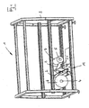
- the supply unit serves for supplying a flat material and, in the illustrated embodiment, specifically for feeding a weldable plastic or packaging film 2 to a packaging machine (not shown).
- the supply unit 1 has for this purpose on a machine frame 3 u.a. two with their axis in the horizontal direction oriented parallel mandrels 4 and 5, each for receiving a roll 6 or 7 (film roll) of the plastic or packaging film 2 are used, of which one role each in running packaging machine in use role is, from which the film 2 is withdrawn in the direction of arrow A and the packaging machine is supplied, while the other role is available as an exchange or connection roller for a roll change.
- the Figures 2 and 3 show - in each case in a state of the supply unit 1 immediately before a roll change - again the two mandrels 4 and 5, on these thorns arranged rollers 6 and 7, of which in the illustrated state, the roller 7 is in use and the roller 6 for a roll change is ready, as well as more with their axes parallel to each other and parallel to the mandrels 4 and 5 arranged deflection and guide rollers 8 - 10 for the packaging film 2.
- the deflection and guide rollers 8-10 are both ends in a frame 11 also on Machine frame 3 mounted connection or welding station 12 rotatably mounted.
- the guide roller 8 is assigned to the mandrel 4 and the guide roller 9 the mandrel 5.
- the two guide rollers 10 together with another Roller 13 means 14 in particular for the controlled change or cancellation of the film tension during the roll change.
- this film 2 is guided over all three rollers 10 and 13.
- the roller 13 at both ends rotatably mounted on a respective pivot arm 13.1, on which an actuator, such as a pneumatic cylinder 13.2 for a controlled pivoting of the pivot arm 13.1 and thus the roller 13 acts.
- the roller 13 is used in conjunction with the film clamping device for printing image correct positioning of the film.
- Another component of the welding station 12 is a double-ended in frame 11 rotatably mounted pinch roller 15 which forms a clamping slot 16, in the illustrated embodiment in that the pinch roller 15 at least on their required for the function of the welding station 12 part length in two parts from the two sides
- the clamping slot 16 arranged parts 15.1 and 15.2 is executed, which are clamped for clamping each one of the beginning of the film against each other.
- the rotation of the pinch roller 15 and possibly also the opening and closing of the nip 16 carried out in the illustrated embodiment manually with a rotary and switching crank 17, which is provided at one end of the pinch roller 15.
- Component of the welding station 12 are further two heatable welding rails 18, which lie with their longitudinal extent parallel to the axis of rotation of the pinch roller 15, offset by an angle of slightly smaller than 180 ° about this axis of rotation and controlled by actuators (eg pneumatic cylinder) on the Pinch roller 15 are movable to and from this path.
- actuators eg pneumatic cylinder
- the joining of the film beginning with the pinch roller 15 is carried out in such a way that when the roll is changed, a side-to-side film connection takes place.
- the pinch roller 15 is rotated after attaching the beginning of the film so that the direction of rotation B is opposite to the film adjacent to the peripheral region of the pinch roller 15 of the direction of movement A of the film used.
- an alignment rail 19 is provided, which is oriented with its longitudinal extent parallel to the axis of the pinch roller 15 and extends over the entire film width.
- Ausrichtschiene 19 which is ready for the roll change film 2 of the roller 6 with provided on the film markers, such as print marks 2.1, aligned exactly.
- the alignment of the film on the alignment rail takes place in such a way that the marking applied on the film (print mark) is aligned with the alignment rail. This is done, for example, manually by the operator, who moves the film forward or back after insertion into the nip of the clamping shaft.
- the pinch roller 15 is then secured in a suitable manner against rotation.
- the alignment rail 19 is pivotally provided.
- control computer 21 of the packaging machine connected to the sensor 20 recognizes the imminent consumption of the roll 6, 7 in use, the roll change is initiated by the control computer 21.
- the sensor 20 or by another sensor 22, which scans on the film 2 existing markers, such as the print marks 2.1, finally, the slower removal of the film 2 is stopped.
- the film between the used roller 6,7 and the packaging machine is now clamped by the clamping rail 14.1.
- the actuator 13.2 and the associated pivoting of the pivot arm and arranged on this pulley 13 is now removed as much film from the roller 7 until the mark (print mark) of the film is detected by another sensor 20. This is the position in which a transition and / or printing image correct connection of the film 2 of the reeled film roll 6 is guaranteed to the film roll 2 used until then on the associated welding rail.
- the initially permanent bias of the film 2 is reduced or eliminated at least in the region of the weld to be created by controlled pivoting of the roller 13 with the pneumatic cylinder 13.2.
- a new roll 7 is placed on the mandrel 5 and the beginning of this role by clamping in the clamping slot 16 on the pinch roller 15 position and connection accurately attached and the Pinch roller rotated by means of the crank 17 so that the first inserted from above into the clamping slot 16 film 2, the pinch roller in turn encloses a large part of the roll circumference, but at least the film 2 of the roll 6 used facing peripheral region of the pinch roller at least one layer of the Foil 2 is surrounded and also the film 2 ready for the transition and / or printing image correct connection is exactly aligned.
- the pinch roller 15 optionally in conjunction with a turning back of the roller 7 provided on the mandrel 5, in turn, the required film tension between this roller and the pinch roller 15 is set.
- rollers 6 and 7 are already aligned exactly on the spines 4 and 5. This alignment then takes place so that the center lines of the films withdrawn from the rollers 7 and 6 lie in a common plane perpendicular to the axes of the mandrels 4 and 5 and preferably also in the center line of the product group.
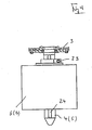
- FIG. 4 again shows one of the two mandrels 4 and 5 in detail, together with a roller 6 and 7.
- a roller stopper 23 is provided axially adjustable. The setting of this stop is done for example by using a mandrel 4 or 5 also provided tape measure 24 or other aids, such as sensors, etc.
Landscapes
- Engineering & Computer Science (AREA)
- Mechanical Engineering (AREA)
- Replacement Of Web Rolls (AREA)
- Auxiliary Devices For And Details Of Packaging Control (AREA)
- Controlling Rewinding, Feeding, Winding, Or Abnormalities Of Webs (AREA)
- Pinball Game Machines (AREA)
- Feeding And Guiding Record Carriers (AREA)
- Adornments (AREA)
- Wrappers (AREA)
Description
- Die Erfindung bezieht sich auf ein Verfahren gemäß Oberbegriff Patentanspruch 1 sowie auf eine Versorgungseinheit zum Durchführen dieses Verfahrens gemäß Oberbegriff Patentanspruch 9.
- Ein Verfahren der gattungsmäßigen Art ist bekannt (
DE 10 2004 032 528 B3 ). Bei diesem bekannten Verfahren erfolgt das lagegenaue Befestigen des Anfangs- oder Anschlussbereichs des Flachmaterials der für einen Rollenwechsel bereit gestellten Anschlussrolle unter Verwendung einer Klemmschiene, die außerhalb der Versorgungseinheit bzw. der dort für den Rollenwechsel vorgesehenen Verbindungsstation unter Verwendung einer Lehre an dem Anfang des Flachmaterials der Anschlussrolle befestigt wird. - Dies bedeutet, dass die am Anfang des Flachmaterials der Anschlussrolle vorgesehene Klemmschiene zusammen mit dieser Anschlussrolle an die Verbindungsstation transportiert und dann dort an dem Positionierelement befestigt werden muss, was zumindest ein relativ aufwendiges Handling bedeutet und bei beengten Platzverhältnissen vielfach nicht durchführbar ist.
- Aufgabe der vorliegenden Erfindung ist es, die Bereitstellung einer Anschlussrolle für den Rollenwechsel zu vereinfachten. Zur Lösung dieser Aufgabe ist ein Verfahren entsprechend dem Patentanspruch 1 ausgebildet. Eine Versorgungseinheit zur Durchführung dieses Verfahrens ist Gegenstand des Patentanspruches 9.
- Bei der Erfindung erfolgt die Verbindung zwischen dem Anfang der bereitzustellenden Rolle des Flachmaterials direkt an dem Positionierelement der Verbindungsstation durch Klemmen, d.h. dieses Positionierelement ist als Klemmelement oder Klemmwalze ausgebildet. Nach der Klemmbefestigung erfolgt dann durch Drehen, beispielsweise durch manuelles Drehen der Klemmwalze das lage- und/oder anschlussgenaue Ausrichten des Flachmaterials der Anschlussrolle, zur Erzielung eines übergangsrichtigen Anschließens des Flachmaterials beim Rollenwechsel.
- Weiterbildungen sind Gegenstand der Unteransprüche. Die Erfindung wird im Folgenden anhand der Figuren an einem Ausführungsbeispiel näher erläutert. Es zeigen:
- Fig. 1
- in vereinfachter Darstellung und in Seitenansicht eine Versorgungseinheit zum Zuführen eines bahnförmigen Flachmaterials, beispielsweise eines Folienmaterials an eine Verpackungsmaschine oder dergleichen Verarbeitungsmaschine;
- Fig. 2
- in Seitenansicht eine Verbindungsstation der Versorgungseinheit zum Verbinden des Flachmaterials beim Wechseln einer aufgebrauchten Vorratsrolle des Flachmaterials gegen eine neue Vorratsrolle;
- Fig. 3
- in schematischer Darstellung die wesentlichen Elemente der Verbindungsstation der
Fig. 2 ; - Fig. 4
- in Einzeldarstellung einen der Dorne (Foliendorne) der Vorrichtung gemäß
Figur 1 . - Die in den Figuren allgemein mit 1 bezeichnete Versorgungseinheit dient zum Zuführen eines Flachmaterials und bei der dargestellten Ausführungsform speziell zum Zuführen einer schweißbaren Kunststoff- bzw. Verpackungsfolie 2 an eine nicht dargestellte Verpackungsmaschine. Die Versorgungseinheit 1 besitzt hierfür an einem Maschinenrahmen 3 u.a. zwei mit ihrer Achse in horizontaler Richtung orientierte parallele Dorne 4 und 5, die jeweils zur Aufnahme einer Rolle 6 bzw. 7 (Folienrolle) der Kunststoff- bzw. Verpackungsfolie 2 dienen, von denen eine Rolle jeweils die bei laufender Verpackungsmaschine die in Verwendung befindliche Rolle ist, von der die Folie 2 in Richtung des Pfeils A abgezogen und der Verpackungsmaschine zugeführt wird, während die andere Rolle als Austausch oder Anschlussrolle für einen Rollenwechsel bereit steht.
- Die
Figuren 2 und3 zeigen - jeweils in einem Zustand der Versorgungseinheit 1 unmittelbar vor einem Rollenwechsel - nochmals die beiden Dorne 4 und 5, die auf diesen Dornen- angeordneten Rollen 6 und 7, von denen in dem dargestellten Zustand die Rolle 7 in Verwendung ist und die Rolle 6 für einen Rollenwechsel bereitsteht, sowie weitere mit ihren Achsen parallel zueinander und parallel zu den Dornen 4 und 5 angeordnete Umlenk- und Führungswalzen 8 - 10 für die Verpackungsfolie 2. Die Umlenk- und Führungswalzen 8-10 sind jeweils beidendig in einem Rahmen 11 einer ebenfalls am Maschinengestell 3 montierten Verbindungs- bzw. Schweißstation 12 drehbar gelagert. - Die Umlenkwalze 8 ist dabei dem Dorn 4 und die Umlenkwalze 9 dem Dorn 5 zugeordnet. Die beiden Umlenkwalzen 10 bilden zusammen mit einer weiteren Walze 13 eine Einrichtung 14 insbesondere zur gesteuerten Änderung oder Aufhebung der Folienspannung während des Rollenwechsels. Hierfür ist diese Folie 2 über alle drei Rollen 10 und 13 geführt. Die Walze 13 beidendig an jeweils einem Schwenkarm 13.1 drehbar gelagert, auf den ein Stellglied, beispielsweise ein Pneumatikzylinder 13.2 für ein gesteuertes Schwenken des Schwenkarmes 13.1 und damit der Walze 13 einwirkt. Die Walze 13 wird in Verbindung mit der Folienklemmeinrichtung auch zur druckbildrichtigen Positionierung der Folie verwendet.
- Weiterer Bestandteil der Schweißstation 12 ist eine beidendig im Rahmen 11 drehbar gelagerte Klemmwalze 15, die einen Klemmschlitz 16 bildet, und zwar bei der dargestellten Ausführungsform dadurch, dass die Klemmwalze 15 zumindest auf ihrer für die Funktion der Schweißstation 12 erforderlichen Teillänge zweiteilig aus den beiden beidseitig vom Klemmschlitz 16 angeordneten Teilen 15.1 und 15.2 ausgeführt ist, die zum Festklemmen jeweils eines Folienanfangs gegeneinander verspannbar sind. Das Drehen der Klemmwalze 15 und gegebenenfalls auch das Öffnen und Schließen des Klemmspalts 16 erfolgen bei der dargestellten Ausführungsform manuell mit einer Dreh- und Schaltkurbel 17, die an einem Ende der Klemmwalze 15 vorgesehen ist.
- Bestandteil der Schweißstation 12 sind weiterhin zwei beheizbare Schweißschienen 18, die mit ihrer Längserstreckung parallel zur Drehachse der Klemmwalze 15 liegen, um einen Winkel von etwas kleiner als 180° um diese Drehachse versetzt angeordnet sind sowie durch Betätigungselemente (z.B. Pneumatik-Zylinder) gesteuert auf die Klemmwalze 15 zu und von dieser Weg bewegbar sind.
- Für einen Rollenwechsel beispielsweise zwischen der in den
Figuren 2 und3 in Verwendung befindlichen und nahezu verbrauchten Rolle 7 und der bereitstehenden neuen Rolle 6 ist letztere mit ihrem Folienanfang über die Umlenkwalze 8 geführt im Klemmspalt 16 der Klemmwalze 15 gehalten. Das Befestigen des Folienanfangs im Klemmschlitz 16 der Klemmwalze 15 erfolgt hierbei grundsätzlich so, dass der Folienanfang von oben her in den geöffneten Klemmspalt 16 eingesetzt, dieser dann zum Festklemmen der Folie 2 geschlossen wird. Anschließend wird die Klemmwalze 15 mit der Kurbel 17 manuell auf jeden Fall soweit gedreht, dass ein der Folie 2 der verwendeten Rolle 7 unmittelbar gegenüberliegender Umfangsbereich der Klemmwalze 15 zumindest einlagig mit der Folie 2 der für einen Rollenwechsel bereitgestellten Rolle 6 abgedeckt ist. - Das Verbinden des Folienanfangs mit der Klemmwalze 15 erfolgt dabei weiterhin so, dass beim Rollenwechsel ein seitengleicher Folienanschluss erfolgt. Hierfür wird bei der dargestellten Ausführungsform die Klemmwalze 15 nach dem Befestigen des Folienanfangs so gedreht, dass die Drehrichtung B an dem der verwendeten Folie benachbarten Umfangsbereich der Klemmwalze 15 der Bewegungsrichtung A der verwendeten Folie entgegengesetzt ist.
- Um ein übergangs- und/oder druckbildrichtiges Anschließen der Folien beim Rollenwechsel zu gewährleisten, ist eine Ausrichtschiene 19 vorgesehen, die mit ihrer Längserstreckung parallel zur Achse der Klemmwalze 15 orientiert ist und sich über die gesamte Folienbreite erstreckt. An dieser Ausrichtschiene 19 wird die für den Rollenwechsel bereitstehende Folie 2 der Rolle 6 mit an der Folie vorgesehenen Markierungen, beispielsweise Druckmarken 2.1, exakt ausgerichtet.
- Das Ausrichten der Folie an der Ausrichtschiene erfolgt in der Weise, dass die auf der Folie aufgebrachte Markierung (Druckmarke) an der Ausrichtschiene ausgerichtet wird. Dies erfolgt beispielsweise manuell durch den Bediener, wobei dieser die Folie nach dem Einführen in den Klemmspalt der Klemmwelle vor- oder zurückbewegt.
- Nach dem Einspannen des Folienanfangs im Klemmspalt 16 erfolgt die lage- und anschlussrichtige Ausrichtung für den Anschweißvorgang durch eine 360° Drehung der Klemmwelle gegen die Laufrichtung der in Verwendung befindlichen Folienrolle.
- Die Klemmwalze 15 wird anschließend in geeigneter Weise gegen Verdrehen gesichert.
- Um diese Ausrichtschiene sowohl beim Bereitstellen einer Rolle auf dem Dorn 4, als auch beim Bereitstellen einer Rolle auf dem Dorn 5 verwenden zu können und insbesondere auch die Zugänglichkeit der Klemmwalze 15 zu verbessern, ist die Ausrichtschiene 19 schwenkbar vorgesehen.
- Nach dem Ausrichten und/oder Festklemmen der Folie kann es zur Erzielung einer ausreichenden Folienspannung zwischen Rolle 6 und Klemmwalze 15 notwendig sein, die bereitstehende Rolle 6 etwas in Richtung einer erhöhten Folienspannung zu drehen.
- Durch einen in der
Figur 2 schematisch mit 20 angedeuteten Sensor werden die, an der von der Rolle 7 abgezogenen Folie 2 befindlichen Druckmarken 2.1 ständig überwacht. Alternativ kann durch geeignete Sensoren auch der Durchmesser der Rollen 6, 7 überwacht werden. - Erkennt ein mit dem Sensor 20 verbundener Steuerrechner 21 der Verpackungsmaschine den unmittelbar bevorstehenden Verbrauch der in Verwendung befindlichen Rolle 6, 7, so wird durch den Steuerrechner 21 der Rollenwechsel eingeleitet.
- Hierbei wird zunächst die Verarbeitungsgeschwindigkeit der Verpackungsmaschine gestoppt und somit die Abzugsgeschwindigkeit der Folie 2 von der Rolle 7 verlangsamt.
- Beispielsweise durch den Sensor 20 oder durch einen weiteren Sensor 22, der an der Folie 2 vorhandene Markierungen, beispielsweise die Druckmarken 2.1 abtastet, wird schließlich auch das verlangsamte Abziehen der Folie 2 gestoppt.
- Durch die vorzugsweise automatische Betätigung des Stellgliedes 14.2 wird nun die Folie zwischen verbrauchter Rolle 6,7 und Verpackungsmaschine durch die Klemmschiene 14.1 geklemmt. Durch vorzugsweise automatische Betätigung des Stellgliedes 13.2 und dem damit verbundenen Schwenken des Schwenkarmes und der an diesem angeordneten Umlenkrolle 13 wird nun soviel Folie von der Rolle 7 abgezogen bis die Markierung (Druckmarke) der Folie von einem weiteren Sensor 20 erfasst wird. Dies ist die Position, in welcher an der zugehörigen Schweißschiene ein übergangs- und/oder druckbildrichtiges Anschließen der Folie 2 der bereiststehenden Folienrolle 6 an die bis dahin verwendete Folienrolle 2 gewährleistet ist.
- Anschließend erfolgt dann gesteuert durch den Steuerrechner 21 das Bewegen der Schweiß- und Trennschiene 18 aus der Ausgangsposition in die Schweißposition, in der durch einen Trennschweißvorgang das Verbinden der Folie 2 der Folienrolle 6 mit der an die Verpackungsmaschine führenden Folienbahn sowie zugleich auch ein Trennen der durch diesen Schweißvorgang erzeugten Verbindung von dem Folienrest der verbrauchten oder nahezu verbrauchten Folienrolle 7 erfolgen.
- Um eine fehlerfreie, insbesondere auch belastungsfreie Schweißnaht beim Rollenwechsel zu erreichen, wird durch gesteuertes Schwenken der Walze 13 mit den Pneumatikzylinder 13.2 die zunächst permanente Vorspannung der Folie 2 zumindest im Bereich der zu erstellenden Schweißnaht reduziert oder aufgehoben.
- Nach dem Trennschweißvorgang wird durch gesteuertes Betätigen des Stellgliedes 13.2 und Schwenken des Schwenkarms samt Umlenkrolle 13 der durch das Umwickeln der Klemmwelle entstandene Folienüberschuss zwischen der Klemmeinrichtung 14 und der Folienrolle 6 gespannt und danach die Klemmeinrichtung 14 geöffnet. Diese Vorgehensweise verhindert eine ruckartige Belastung der frischen Schweißnaht nach dem Wideranlaufen der Maschine.
- Beendigung des Trennschweißens, d.h. nach erfolgtem Rollenwechsel läuft die Verpackungsmaschine gesteuert durch den Steuerrechner 21 wieder an, wobei die Folie 2 nunmehr von der Rolle 6 abgezogen wird. Die Rolle 7 wird manuell aus der Versorgungseinheit entnommen. Ebenso auch der an der Klemmwalze 15 vorhandene Folienrest durch Öffnen des Klemmspaltes 16. Für den erneuten Rollenwechsel wird eine neue Rolle 7 auf den Dorn 5 aufgesetzt und der Anfang dieser Rolle durch Festklemmen im Klemmschlitz 16 an der Klemmwalze 15 lage- und anschlußgenau befestigt und die Klemmwalze mit Hilfe der Kurbel 17 so gedreht, dass die zunächst von oben her in den Klemmschlitz 16 eingesetzte Folie 2 die Klemmwalze wiederum auf einem Großteil des Walzenumfanges umschließt, zumindest aber der der Folie 2 der verwendeten Rolle 6 zugewandte Umfangsbereich der Klemmwalze wenigstens einlagig von der Folie 2 umgeben ist und außerdem die bereitstehende Folie 2 für das übergangs- und/oder druckbildrichtiges Anschließen exakt ausgerichtet ist. Durch das Drehen der Klemmwalze 15, gegebenenfalls in Verbindung mit einem Zurückdrehen der auf dem Dorn 5 vorgesehenen Rolle 7 wird wiederum die erforderliche Folienspannung zwischen dieser Rolle und der Klemmwalze 15 eingestellt.
- Beim Verbrauch der auf dem Dorn 4 befindlichen Rolle 6 erfolgt dann in analoger Weise erneut ein Rollenwechsel.
- Für den Rollenwechsel ist weiterhin auch erforderlich, dass die Rollen 6 und 7 bereits auf den Dornen 4 und 5 exakt ausgerichtet sind. Diese Ausrichtung erfolgt dann so, dass die Mittellinien der von den Rollen 7 bzw. 6 abgezogenen Folien in einer gemeinsamen Ebene senkrecht zu den Achsen der Dorne 4 bzw. 5 und dabei bevorzugt auch in der Mittellinie der Produktgruppe liegen.
- Die
Figur 4 zeigt nochmals einen der beiden Dorne 4 bzw. 5 im Detail, zusammen mit einer Rolle 6 bzw. 7. Auf jedem Dorn ist ein Rollenanschlag 23 axial einstellbar vorgesehen. Die Einstellung dieses Anschlags erfolgt beispielsweise unter Verwendung eines an dem Dorn 4 bzw. 5 ebenfalls vorgesehenen Maßbandes 24 oder anderer Hilfsmittel, beispielsweise Sensoren usw. - Die Erfindung wurde voranstehend an einem Ausführungsbeispiel beschrieben. Es versteht sich, dass zahlreiche Änderungen sowie Abwandlungen möglich sind, ohne dass dadurch der der Erfindung zugrunde liegende Erfindungsgedanke verlassen wird.
-
- 1
- Versorgungsteil
- 2
- Flachmaterial oder Folie
- 2.1
- Druckmarke
- 3
- Maschinenrahmen
- 4, 5
- Dorn
- 6, 7
- Rolle bzw. Folienrolle
- 8-10
- Umlenkwalze
- 11
- Rahmen
- 12
- Schweiß- oder Bindungsstation
- 13
- Walze
- 13.1
- Schwenkarm
- 13.2
- Betätigungseinrichtung bzw. Zylinder für Schwenkarm 13.1
- 14
- Folienklemmeinrichtung
- 14.1
- Klemmbalken
- 14.2
- Betätigungseinrichtung für Klemmbalken
- 15
- Klemmwalze
- 15.1, 15.2
- Teil der Klemmwalze 15
- 16
- Klemmspalt
- 17
- Kurbel
- 18
- Schweiß- und Trennschiene
- 19
- Ausrichtschiene
- 20
- Sensor
- 21
- Rechner
- 22
- Sensor
- 23
- Rollenanschlag
- 24
- Maßband
- A
- Bewegungsrichtung der der Verpackungsmaschine zugeführten Folie 2
- B
- Drehrichtung der Klemmwalze
Claims (10)
- Verfahren zum Bereitstellen einer Anschlussrolle (7, 6) bei einem stehenden Rollenwechsel bei einer Versorgungseinheit (1), die zum Zuführen eines bahnförmigen Flachmaterials (2) an eine Verpackungsmaschine oder dergleichen Verarbeitungsmaschine von jeweils einen Flachmaterial-Vorrat bildenden Rollen (6, 7) dient, wobei für den Rollenwechsel, bei dem in einer Anschluss- oder Verbindungsstation (12) das Flachmaterial (2) der in Verwendung befindlichen Rolle (6, 7) mit einem Anfang- oder Anschlussbereich der bereitstehenden Anschlussrolle (7, 6) verbunden wird, dieser Anschlussbereich in der Verbindungsstation für ein in Bahnrichtung übergangsrichtiges Anschließen an einem Positionierelement (15) exakt positioniert wird, die exakte Positionierung des jeweiligen Anschlussbereiches des Flachmaterials (2) der Anschlussrolle (7, 6) in der Anschluss- oder Verbindungsstation (12) erfolgt,
dadurch gekennzeichnet, dass
hierfür zunächst das Flachmaterial (2) der Anschlussrolle am Positionierelement (15) durch Festklemmen befestigt und anschließend ein Ausrichten des Anschlussbereichs durch Drehen des Positionierelementes (15) und Aufwickeln des Flachmaterials (2) der Anschlussrolle auf das Positionierelement (15) erfolgt, und zwar unter Verwendung von an dem Flachmaterial (2) der Anschlussrolle vorgesehenen Markierungen (2.1) sowie wenigstens eines Ausrichtelementes (19) an der Verbindungsstation (12). - Verfahren nach Anspruch 1, dadurch gekennzeichnet, dass das Positionierelement als Klemmwalze (15) ausgebildet ist.
- Verfahren nach Anspruch 2, dadurch gekennzeichnet, dass das Positionierelement als Klemmwalze (15) mit Klemmspalt (16) ausgebildet ist.
- Verfahren nach einem der vorhergehenden Ansprüche, dadurch gekennzeichnet, dass der Anschlussbereich des Flachmaterials (2) der Anschlussrolle (7, 6) das Positionierelement (15) an wenigstens einem Umfangsbereich abdeckt, der dem Flachmaterial (2) der in Verwendung befindlichen Rolle (6, 7) benachbart liegt.
- Verfahren nach Anspruch 4, dadurch gekennzeichnet, dass nach dem Verbinden des Anschlussbereichs mit dem Positionierelement (15) dieses um seine Achse derart gedreht wird, dass das Flachmaterial (2) einen dem Flachmaterial (2) der in Verwendung befindlichen Rolle (6, 7) benachbarten Umfangsbereich des Positionierelementes (15) wenigstens einlagig abdeckt.
- Verfahren nach einem der vorhergehenden Ansprüche, dadurch gekennzeichnet, dass das lagegenaue Ausrichten des Flachmaterials (2) der Anschlussrolle (7, 6) unter Verwendung einer an der Verbindungsstation (12) vorgesehenen Ausrichtschiene (19) erfolgt.
- Verfahren nach einem der vorhergehenden Ansprüche, dadurch gekennzeichnet, dass die Verbindung des in Verwendung befindlichen Flachmaterials (2) mit dem Flachmaterial (2) der Anschlussrolle (7, 6) überlappend ausgeführt wird.
- Verfahren nach einem der vorhergehenden Ansprüche, dadurch gekennzeichnet, dass bei Verwendung eines Flachmaterials in Form einer schweißbaren Folie (2) das Verbinden beim Rollenwechsel durch Schweißen, vorzugsweise durch Trennschweißen erfolgt.
- Versorgungseinheit zum Zuführen eines bahnartigen Flachmaterials an eine Verpackungsmaschine oder dergleichen Verarbeitungsmaschine mit wenigstens zwei Rollenaufnahmen (4, 5) zur Aufnahme jeweils eines Flachmaterial-Vorrats in Form einer Rolle (6, 7), von denen wenigstens eine Rolle (6, 7) die in Verwendung befindliche Rolle, von der das Flachmaterial (2) während des Betriebes der Verpackungsmaschine oder dergleichen Verarbeitungsmaschine abgezogen wird, und wenigstens eine weitere Rolle eine für einen stehenden Rollenwechsel bereitstehende Anschlussrolle (7, 6) bilden, mit einer Verbindungsstation (12) durch die das Flachmaterial (2) der in Verwendung befindlichen Rolle (6) hindurchgeführt ist und an der an einer Verbindungsposition (18) ein Anschlussbereich des Flachmaterials der Anschlussrolle für einen in Bahnrichtung übergangsrichtigen Anschluss exakt positioniert an einem Halte- und Positionierungselement (15) angeordnet ist,
dadurch gekennzeichnet,
dass das Halte- und Positionierelement eine um ihre Achse manuell drehbare Klemmwalze (15) geeignet zum Klemmen und Aufwickeln des Flachmaterials der Anschlussrolle (7, 6) ist, und dass an der Verbindungsstation (12) für das in Bahnrichtung übergangsrichtiges Anordnen des Anschlussbereichs der Anschlussrolle (7, 6) Ausrichtmittel (19) zum Ausrichten des Flachmaterials der Anschlussrolle an an diesem vorhandenen Markierungen (2.1) vorgesehen sind. - Versorgungseinheit nach Anspruch 9, dadurch gekennzeichnet, dass die Ausrichtmittel von wenigstens einer, vorzugsweise schwenkbaren Ausrichtschiene (19) gebildet sind.
Applications Claiming Priority (2)
| Application Number | Priority Date | Filing Date | Title |
|---|---|---|---|
| DE102006037189A DE102006037189A1 (de) | 2006-08-09 | 2006-08-09 | Verfahren zum Durchführen eines Rollenwechsels bei einer Versorgungseinheit zum Zuführen eines bahnartigen Flachmaterials an eine Verpackungsmaschine oder dergleichen Verarbeitungsmaschine sowie Versorgungseinheit zum Durchführen dieses Verfahrens |
| PCT/EP2007/006965 WO2008017450A2 (de) | 2006-08-09 | 2007-08-07 | Verfahren zum durchführen eines rollenwechsels sowie spleisser zum durchführen dieses verfahren |
Publications (2)
| Publication Number | Publication Date |
|---|---|
| EP1968874A2 EP1968874A2 (de) | 2008-09-17 |
| EP1968874B1 true EP1968874B1 (de) | 2010-02-24 |
Family
ID=38871546
Family Applications (1)
| Application Number | Title | Priority Date | Filing Date |
|---|---|---|---|
| EP07818014A Active EP1968874B1 (de) | 2006-08-09 | 2007-08-07 | VERFAHREN ZUM Bereitstellen einer Anschlussrolle SOWIE VERSORGUNGSEINHEIT ZUM DURCHFÜHREN DIESES VERFAHRENS |
Country Status (9)
| Country | Link |
|---|---|
| US (1) | US20100024364A1 (de) |
| EP (1) | EP1968874B1 (de) |
| JP (1) | JP2010500258A (de) |
| CN (1) | CN101484375A (de) |
| AT (1) | ATE458685T1 (de) |
| BR (1) | BRPI0714282A2 (de) |
| DE (2) | DE102006037189A1 (de) |
| MX (1) | MX2009001299A (de) |
| WO (1) | WO2008017450A2 (de) |
Families Citing this family (20)
| Publication number | Priority date | Publication date | Assignee | Title |
|---|---|---|---|---|
| EP2258643B1 (de) | 2009-06-01 | 2015-01-14 | Tetra Laval Holdings & Finance S.A. | Verfahren zur Beschickung einer Versorgungsstation einer Verpackungseinheit mit einer neuen Rolle aus Blattverpackungsmaterial, Blattverpackungsmaterialhalter und Gabelstapler |
| DE102010021732A1 (de) | 2010-05-27 | 2011-12-01 | Krones Ag | Spleißvorrichtung und Verfahren zum Spleißen eines bahnartigen Flachmaterials |
| DE102011084935A1 (de) | 2011-10-21 | 2013-04-25 | Koenig & Bauer Aktiengesellschaft | Verfahren zum Einziehen zumindest einer Materialbahn in eine Verarbeitungsvorrichtung |
| CN102490195B (zh) * | 2011-12-05 | 2014-08-06 | 常德金鹏印务有限公司 | 一种圆压圆高速卷筒模切机及其使用方法 |
| DE102013110944A1 (de) * | 2013-10-02 | 2015-04-02 | Krones Aktiengesellschaft | Verfahren und Vorrichtung zum Wechseln von Trägereinheiten mit auf Vorratsrollen aufgewickeltem flächigem Verpackungsmaterial innerhalb einer Verpackungsmaschine |
| JP6408783B2 (ja) * | 2014-04-14 | 2018-10-17 | 高周波熱錬株式会社 | 環状ワークの加熱装置及び方法、並びに加熱コイル |
| EP3143666B1 (de) * | 2014-05-13 | 2018-12-19 | Centre National de la Recherche Scientifique (CNRS) | Mikrowellenherd |
| CN104803041B (zh) * | 2015-03-11 | 2016-11-30 | 重庆市巴南区前进机械厂 | 一种使用电磁驱动装置的食品包装装置及其使用方法 |
| US10421111B2 (en) * | 2015-04-17 | 2019-09-24 | Ball Corporation | Method and apparatus for controlling an operation performed on a continuous sheet of material |
| CN105460661B (zh) * | 2015-11-30 | 2017-05-31 | 陕西北人印刷机械有限责任公司 | 一种印刷机新旧料对接装置及其对接方法 |
| DE102016200581B4 (de) * | 2016-01-19 | 2023-01-12 | Krones Aktiengesellschaft | Verfahren zur Zuförderung, Bereitstellung und zum Austausch von Rollen mit Verpackungsmaterial in einer Verpackungsmaschine |
| ITUA20162968A1 (it) * | 2016-04-28 | 2017-10-28 | Mbp Srl | Confezionatrice verticale con sistema di svolgimento film agevolato |
| WO2019017965A1 (en) | 2017-07-21 | 2019-01-24 | Hewlett-Packard Development Company, L.P. | Indicating materials within material cartridges |
| CA3111827C (en) * | 2018-09-10 | 2023-10-17 | Ball Corporation | Method and apparatus for controlling an operation performed on a continuous sheet of material |
| JP7236719B2 (ja) * | 2018-10-04 | 2023-03-10 | 株式会社イシダ | 製袋包装機 |
| CN109534052B (zh) * | 2018-12-25 | 2020-10-23 | 广州市万世德智能装备科技有限公司 | 一种自动接膜装置 |
| CN113511390B (zh) * | 2021-06-03 | 2024-01-19 | 温州市佳本印业有限公司 | 一种纸箱包装箱用的定型封口设备及其封口方法 |
| IT202200019791A1 (it) * | 2022-09-27 | 2024-03-27 | Ima Spa | Macchina per la formazione di sacchetti filtro per prodotti da infusione. |
| CN115648379B (zh) * | 2022-11-11 | 2023-11-10 | 江苏万航木业有限公司 | 用于家居家具板材封边装置及封边方法 |
| CN117755578A (zh) * | 2023-12-29 | 2024-03-26 | 广州市万世德智能装备科技有限公司 | 一种高速膜包机 |
Family Cites Families (19)
| Publication number | Priority date | Publication date | Assignee | Title |
|---|---|---|---|---|
| DE285356C (de) * | ||||
| US3035787A (en) * | 1958-12-05 | 1962-05-22 | Ota | Automatic joining device for reeled band materials |
| US3227594A (en) * | 1962-01-22 | 1966-01-04 | Du Pont | Method and apparatus for splicing indefinite length webs |
| DE2320424A1 (de) * | 1972-09-04 | 1974-03-14 | Lara Sa | Verfahren zum kontinuierlichen verpacken von gegenstaenden und vorrichtung zum durchfuehren des verfahrens |
| DE2934115C2 (de) * | 1979-08-23 | 1981-10-22 | Angerer, Klaus, 8551 Röttenbach | Verfahren und Vorrichtung zum Speichern endloser Metallbänder aus endlichen Walzbandlängen |
| EP0091216B1 (de) * | 1982-03-31 | 1986-07-09 | Peter Hurst | Vorrichtung zum Verbinden von Bahnen |
| DE3923163A1 (de) * | 1989-07-13 | 1991-01-17 | Kronseder Maschf Krones | Verfahren und vorrichtung zum anspleissen von bedruckten etikettenbaendern |
| DE9016526U1 (de) * | 1990-12-05 | 1991-02-21 | Rovema - Verpackungsmaschinen GmbH, 6301 Fernwald | Vorrichtung zur Förderung einer endlosen Folie aus Kunststoff o.dgl. |
| DE4325944A1 (de) * | 1993-08-03 | 1995-02-09 | Focke & Co | Verfahren und Vorrichtung zum Verbinden von Materialbahnen, insbesondere aus Verpackungsmaterial |
| DE4436719A1 (de) * | 1994-10-14 | 1996-04-18 | Schmermund Maschf Alfred | Spleißer für bobinenartig aufgewickelte Verpackungsmaterialbahnen |
| DE19522110A1 (de) * | 1995-06-19 | 1997-01-02 | Kisters Maschinenbau Gmbh | Verfahren zum Verschweißen zweier von jeweils einer Vorratsrolle kommender Folienbahnen in einer Verpackungsmaschine |
| US6068161A (en) * | 1997-07-01 | 2000-05-30 | Creative Edge Design Group, Ltd. | Stackable, thin-walled containers having a structural load distributing feature permitting caseless shipping |
| US6451145B1 (en) * | 1998-03-09 | 2002-09-17 | Frontier Industrial Technology, Inc. | Web splicing system |
| US6247507B1 (en) * | 1998-09-30 | 2001-06-19 | Creative Edge Design Group, Ltd. | System for processing and packaging milk and other beverages |
| US6484475B1 (en) * | 1999-02-02 | 2002-11-26 | Kisters Kayat, Inc. | Modular packaging machine |
| JP4412573B2 (ja) * | 2001-04-12 | 2010-02-10 | 株式会社東京自働機械製作所 | フィルム接続供給装置 |
| ITFI20020178A1 (it) * | 2002-09-25 | 2004-03-26 | Fosber Spa | Giuntatrice per unire tra loro due materiali nastriformi, svolgitore comprendente detta giuntatrice e relativo metodo |
| DE10301347B4 (de) * | 2003-01-16 | 2013-05-08 | Pester Pac Automation Gmbh | Banderoliermaschine |
| DE102004032528C5 (de) * | 2004-07-06 | 2012-04-05 | Khs Gmbh | Verfahren zum Durchführen eines Rollenwechsels bei einer Versorgungseinheit zum Zuführen eines bahnartigen Flachmaterials an eine Verpackungsmaschine oder dergleichen Verarbeitungsmaschine sowie Versorgungseinheit zum Durchführen dieses Verfahrens |
-
2006
- 2006-08-09 DE DE102006037189A patent/DE102006037189A1/de not_active Withdrawn
-
2007
- 2007-08-07 MX MX2009001299A patent/MX2009001299A/es not_active Application Discontinuation
- 2007-08-07 CN CNA2007800213913A patent/CN101484375A/zh active Pending
- 2007-08-07 DE DE502007002916T patent/DE502007002916D1/de active Active
- 2007-08-07 BR BRPI0714282-0A patent/BRPI0714282A2/pt not_active Application Discontinuation
- 2007-08-07 AT AT07818014T patent/ATE458685T1/de active
- 2007-08-07 JP JP2009523194A patent/JP2010500258A/ja not_active Withdrawn
- 2007-08-07 WO PCT/EP2007/006965 patent/WO2008017450A2/de not_active Ceased
- 2007-08-07 EP EP07818014A patent/EP1968874B1/de active Active
-
2009
- 2009-02-05 US US12/365,988 patent/US20100024364A1/en not_active Abandoned
Also Published As
| Publication number | Publication date |
|---|---|
| US20100024364A1 (en) | 2010-02-04 |
| WO2008017450A3 (de) | 2008-03-27 |
| CN101484375A (zh) | 2009-07-15 |
| WO2008017450A2 (de) | 2008-02-14 |
| DE102006037189A1 (de) | 2008-02-14 |
| ATE458685T1 (de) | 2010-03-15 |
| JP2010500258A (ja) | 2010-01-07 |
| BRPI0714282A2 (pt) | 2013-04-24 |
| EP1968874A2 (de) | 2008-09-17 |
| MX2009001299A (es) | 2009-02-16 |
| DE502007002916D1 (de) | 2010-04-08 |
Similar Documents
| Publication | Publication Date | Title |
|---|---|---|
| EP1968874A2 (de) | Verfahren zum durchführen eines rollenwechsels sowie spleisser zum durchführen dieses verfahrens | |
| EP1614646B1 (de) | Verfahren zum Durchführen eines Rollenwechsels bei einer Versorgungseinheit zum Zuführen eines bahnartigen Flachmaterials an eine Verpackungsmaschine | |
| DE3751754T2 (de) | Vorrichtung zum Befestigen einer Ersatzbahn an einer Bahn, die eine programmierte Bewegung durchführt, ohne eine solche Bewegung zu unterbrechen | |
| DE3751729T2 (de) | Vorrichtung zum Befestigen einer Ersatzbahn an eine sich bewegende Bahn | |
| DE3811138C2 (de) | ||
| DE19824797B4 (de) | Beutelherstellungsvorrichtung und Verfahren zum Herstellen von Folienbeutel | |
| DE69914444T2 (de) | Vorrichtung zum Formen einer Spleissverbindung in einer Papierbahn | |
| DE102011080654B4 (de) | Rollenabspulvorrichtung einer Rollen-Rotationsdruckmaschine | |
| WO2016066596A1 (de) | Verfahren und vorrichtung zur handhabung von auf rollen aufgewickeltem flach- und/oder folienmaterial | |
| EP3212552B1 (de) | Verfahren und vorrichtung zur handhabung von auf rollen gewickeltem flach- und/oder folienmaterial | |
| DE69501317T2 (de) | Verfahren zum vorbereiten des bahnanfangs einer vorratsrolle in einem rollenwechsler, rollenwechsler und bahnaufnahmevorrichtung | |
| DE3042383A1 (de) | Glaettvorrichtung | |
| DE4211858C2 (de) | Einrichtung zum kernlosen Aufwickeln von Flachmaterial | |
| EP0706965B1 (de) | Spleisser für bobinenartig aufgewickelte Verpackungsmaterialbahnen | |
| EP1600412B1 (de) | Folienspleissstation | |
| DE4113772A1 (de) | Verfahren zum ersetzen von streifenmaterial an einer fertigungsmaschine | |
| DE69606448T2 (de) | Abwickelvorrichtung für bandförmiges Material | |
| EP3374301B1 (de) | Wickelvorrichtung für bahnförmiges material und verfahren zum einziehen zumindest einer materialbahn in zumindest eine wickelvorrichtung | |
| DE19601668A1 (de) | Folienwickelmaschine zum Umwickeln beladener Paletten | |
| DE69607326T2 (de) | Vorrichtung und verfahren in einer verpackungsmachine | |
| EP0162371B1 (de) | Folien-Vorschubeinheit für eine Tubenherstellungsmaschine | |
| DE69211980T2 (de) | Maschine zur Herstellung von Kunststoffbeuteln mit Mittel zum Ausrichten der Endkante eines ablaufenden Bandes mit der Anfangskante eines neuen Bandes | |
| DE20012889U1 (de) | Automatische Rollenwechseleinrichtungen für Folienwickelmaschinen | |
| DE69117160T2 (de) | Verfahren und Vorrichtung zum Aufwickeln und Lagern von einem bandförmigen Gegenstand | |
| DE202006012205U1 (de) | Vorrichtung zum Durchführen eines Rollenwechsels bei einer Versorgungseinheit zum Zuführen eines bahnartigen Flachmaterials an eine Verpackungsmaschine o.dgl. Verarbeitungsmaschine |
Legal Events
| Date | Code | Title | Description |
|---|---|---|---|
| PUAI | Public reference made under article 153(3) epc to a published international application that has entered the european phase |
Free format text: ORIGINAL CODE: 0009012 |
|
| 17P | Request for examination filed |
Effective date: 20080710 |
|
| AK | Designated contracting states |
Kind code of ref document: A2 Designated state(s): AT BE BG CH CY CZ DE DK EE ES FI FR GB GR HU IE IS IT LI LT LU LV MC MT NL PL PT RO SE SI SK TR |
|
| AX | Request for extension of the european patent |
Extension state: AL BA HR MK RS |
|
| 17Q | First examination report despatched |
Effective date: 20081105 |
|
| RIN1 | Information on inventor provided before grant (corrected) |
Inventor name: SCHAGIDOW, TUCHWAT Inventor name: VAN TRIEL, MANFRED |
|
| RTI1 | Title (correction) |
Free format text: METHOD FOR SUPPLYING A NEW REEL AND SPLICER FOR CARRYING OUT THIS METHOD |
|
| GRAP | Despatch of communication of intention to grant a patent |
Free format text: ORIGINAL CODE: EPIDOSNIGR1 |
|
| DAX | Request for extension of the european patent (deleted) | ||
| GRAS | Grant fee paid |
Free format text: ORIGINAL CODE: EPIDOSNIGR3 |
|
| GRAA | (expected) grant |
Free format text: ORIGINAL CODE: 0009210 |
|
| AK | Designated contracting states |
Kind code of ref document: B1 Designated state(s): AT BE BG CH CY CZ DE DK EE ES FI FR GB GR HU IE IS IT LI LT LU LV MC MT NL PL PT RO SE SI SK TR |
|
| REG | Reference to a national code |
Ref country code: GB Ref legal event code: FG4D Free format text: NOT ENGLISH |
|
| REG | Reference to a national code |
Ref country code: CH Ref legal event code: EP |
|
| REG | Reference to a national code |
Ref country code: IE Ref legal event code: FG4D Free format text: LANGUAGE OF EP DOCUMENT: GERMAN |
|
| REF | Corresponds to: |
Ref document number: 502007002916 Country of ref document: DE Date of ref document: 20100408 Kind code of ref document: P |
|
| REG | Reference to a national code |
Ref country code: NL Ref legal event code: VDEP Effective date: 20100224 |
|
| LTIE | Lt: invalidation of european patent or patent extension |
Effective date: 20100224 |
|
| RAP2 | Party data changed (patent owner data changed or rights of a patent transferred) |
Owner name: KHS GMBH |
|
| PG25 | Lapsed in a contracting state [announced via postgrant information from national office to epo] |
Ref country code: PT Free format text: LAPSE BECAUSE OF FAILURE TO SUBMIT A TRANSLATION OF THE DESCRIPTION OR TO PAY THE FEE WITHIN THE PRESCRIBED TIME-LIMIT Effective date: 20100625 Ref country code: LT Free format text: LAPSE BECAUSE OF FAILURE TO SUBMIT A TRANSLATION OF THE DESCRIPTION OR TO PAY THE FEE WITHIN THE PRESCRIBED TIME-LIMIT Effective date: 20100224 Ref country code: IS Free format text: LAPSE BECAUSE OF FAILURE TO SUBMIT A TRANSLATION OF THE DESCRIPTION OR TO PAY THE FEE WITHIN THE PRESCRIBED TIME-LIMIT Effective date: 20100624 |
|
| PG25 | Lapsed in a contracting state [announced via postgrant information from national office to epo] |
Ref country code: SI Free format text: LAPSE BECAUSE OF FAILURE TO SUBMIT A TRANSLATION OF THE DESCRIPTION OR TO PAY THE FEE WITHIN THE PRESCRIBED TIME-LIMIT Effective date: 20100224 Ref country code: FI Free format text: LAPSE BECAUSE OF FAILURE TO SUBMIT A TRANSLATION OF THE DESCRIPTION OR TO PAY THE FEE WITHIN THE PRESCRIBED TIME-LIMIT Effective date: 20100224 Ref country code: LV Free format text: LAPSE BECAUSE OF FAILURE TO SUBMIT A TRANSLATION OF THE DESCRIPTION OR TO PAY THE FEE WITHIN THE PRESCRIBED TIME-LIMIT Effective date: 20100224 Ref country code: PL Free format text: LAPSE BECAUSE OF FAILURE TO SUBMIT A TRANSLATION OF THE DESCRIPTION OR TO PAY THE FEE WITHIN THE PRESCRIBED TIME-LIMIT Effective date: 20100224 |
|
| REG | Reference to a national code |
Ref country code: IE Ref legal event code: FD4D |
|
| PG25 | Lapsed in a contracting state [announced via postgrant information from national office to epo] |
Ref country code: CY Free format text: LAPSE BECAUSE OF FAILURE TO SUBMIT A TRANSLATION OF THE DESCRIPTION OR TO PAY THE FEE WITHIN THE PRESCRIBED TIME-LIMIT Effective date: 20100224 Ref country code: EE Free format text: LAPSE BECAUSE OF FAILURE TO SUBMIT A TRANSLATION OF THE DESCRIPTION OR TO PAY THE FEE WITHIN THE PRESCRIBED TIME-LIMIT Effective date: 20100224 Ref country code: ES Free format text: LAPSE BECAUSE OF FAILURE TO SUBMIT A TRANSLATION OF THE DESCRIPTION OR TO PAY THE FEE WITHIN THE PRESCRIBED TIME-LIMIT Effective date: 20100604 Ref country code: GR Free format text: LAPSE BECAUSE OF FAILURE TO SUBMIT A TRANSLATION OF THE DESCRIPTION OR TO PAY THE FEE WITHIN THE PRESCRIBED TIME-LIMIT Effective date: 20100525 Ref country code: NL Free format text: LAPSE BECAUSE OF FAILURE TO SUBMIT A TRANSLATION OF THE DESCRIPTION OR TO PAY THE FEE WITHIN THE PRESCRIBED TIME-LIMIT Effective date: 20100224 Ref country code: RO Free format text: LAPSE BECAUSE OF FAILURE TO SUBMIT A TRANSLATION OF THE DESCRIPTION OR TO PAY THE FEE WITHIN THE PRESCRIBED TIME-LIMIT Effective date: 20100224 Ref country code: SE Free format text: LAPSE BECAUSE OF FAILURE TO SUBMIT A TRANSLATION OF THE DESCRIPTION OR TO PAY THE FEE WITHIN THE PRESCRIBED TIME-LIMIT Effective date: 20100224 Ref country code: IE Free format text: LAPSE BECAUSE OF FAILURE TO SUBMIT A TRANSLATION OF THE DESCRIPTION OR TO PAY THE FEE WITHIN THE PRESCRIBED TIME-LIMIT Effective date: 20100224 |
|
| PG25 | Lapsed in a contracting state [announced via postgrant information from national office to epo] |
Ref country code: BG Free format text: LAPSE BECAUSE OF FAILURE TO SUBMIT A TRANSLATION OF THE DESCRIPTION OR TO PAY THE FEE WITHIN THE PRESCRIBED TIME-LIMIT Effective date: 20100524 Ref country code: CZ Free format text: LAPSE BECAUSE OF FAILURE TO SUBMIT A TRANSLATION OF THE DESCRIPTION OR TO PAY THE FEE WITHIN THE PRESCRIBED TIME-LIMIT Effective date: 20100224 Ref country code: SK Free format text: LAPSE BECAUSE OF FAILURE TO SUBMIT A TRANSLATION OF THE DESCRIPTION OR TO PAY THE FEE WITHIN THE PRESCRIBED TIME-LIMIT Effective date: 20100224 |
|
| PLBE | No opposition filed within time limit |
Free format text: ORIGINAL CODE: 0009261 |
|
| STAA | Information on the status of an ep patent application or granted ep patent |
Free format text: STATUS: NO OPPOSITION FILED WITHIN TIME LIMIT |
|
| PG25 | Lapsed in a contracting state [announced via postgrant information from national office to epo] |
Ref country code: DK Free format text: LAPSE BECAUSE OF FAILURE TO SUBMIT A TRANSLATION OF THE DESCRIPTION OR TO PAY THE FEE WITHIN THE PRESCRIBED TIME-LIMIT Effective date: 20100224 |
|
| 26N | No opposition filed |
Effective date: 20101125 |
|
| BERE | Be: lapsed |
Owner name: KHS A.G. Effective date: 20100831 |
|
| PG25 | Lapsed in a contracting state [announced via postgrant information from national office to epo] |
Ref country code: MC Free format text: LAPSE BECAUSE OF NON-PAYMENT OF DUE FEES Effective date: 20100831 Ref country code: IT Free format text: LAPSE BECAUSE OF FAILURE TO SUBMIT A TRANSLATION OF THE DESCRIPTION OR TO PAY THE FEE WITHIN THE PRESCRIBED TIME-LIMIT Effective date: 20100224 |
|
| REG | Reference to a national code |
Ref country code: FR Ref legal event code: ST Effective date: 20110502 |
|
| PG25 | Lapsed in a contracting state [announced via postgrant information from national office to epo] |
Ref country code: BE Free format text: LAPSE BECAUSE OF NON-PAYMENT OF DUE FEES Effective date: 20100831 Ref country code: FR Free format text: LAPSE BECAUSE OF NON-PAYMENT OF DUE FEES Effective date: 20100831 |
|
| PG25 | Lapsed in a contracting state [announced via postgrant information from national office to epo] |
Ref country code: MT Free format text: LAPSE BECAUSE OF FAILURE TO SUBMIT A TRANSLATION OF THE DESCRIPTION OR TO PAY THE FEE WITHIN THE PRESCRIBED TIME-LIMIT Effective date: 20100224 |
|
| REG | Reference to a national code |
Ref country code: CH Ref legal event code: PL |
|
| GBPC | Gb: european patent ceased through non-payment of renewal fee |
Effective date: 20110807 |
|
| PG25 | Lapsed in a contracting state [announced via postgrant information from national office to epo] |
Ref country code: CH Free format text: LAPSE BECAUSE OF NON-PAYMENT OF DUE FEES Effective date: 20110831 Ref country code: LI Free format text: LAPSE BECAUSE OF NON-PAYMENT OF DUE FEES Effective date: 20110831 |
|
| PG25 | Lapsed in a contracting state [announced via postgrant information from national office to epo] |
Ref country code: GB Free format text: LAPSE BECAUSE OF NON-PAYMENT OF DUE FEES Effective date: 20110807 |
|
| PG25 | Lapsed in a contracting state [announced via postgrant information from national office to epo] |
Ref country code: HU Free format text: LAPSE BECAUSE OF FAILURE TO SUBMIT A TRANSLATION OF THE DESCRIPTION OR TO PAY THE FEE WITHIN THE PRESCRIBED TIME-LIMIT Effective date: 20100825 Ref country code: LU Free format text: LAPSE BECAUSE OF NON-PAYMENT OF DUE FEES Effective date: 20100807 |
|
| PG25 | Lapsed in a contracting state [announced via postgrant information from national office to epo] |
Ref country code: TR Free format text: LAPSE BECAUSE OF FAILURE TO SUBMIT A TRANSLATION OF THE DESCRIPTION OR TO PAY THE FEE WITHIN THE PRESCRIBED TIME-LIMIT Effective date: 20100224 |
|
| REG | Reference to a national code |
Ref country code: AT Ref legal event code: MM01 Ref document number: 458685 Country of ref document: AT Kind code of ref document: T Effective date: 20120831 |
|
| PG25 | Lapsed in a contracting state [announced via postgrant information from national office to epo] |
Ref country code: AT Free format text: LAPSE BECAUSE OF NON-PAYMENT OF DUE FEES Effective date: 20120831 |
|
| PGFP | Annual fee paid to national office [announced via postgrant information from national office to epo] |
Ref country code: DE Payment date: 20250820 Year of fee payment: 19 |
|
| P01 | Opt-out of the competence of the unified patent court (upc) registered |
Free format text: CASE NUMBER: UPC_APP_0014580_1968874/2025 Effective date: 20251125 |