EP1966013B1 - Element de raccordement - Google Patents
Element de raccordement Download PDFInfo
- Publication number
- EP1966013B1 EP1966013B1 EP06807687A EP06807687A EP1966013B1 EP 1966013 B1 EP1966013 B1 EP 1966013B1 EP 06807687 A EP06807687 A EP 06807687A EP 06807687 A EP06807687 A EP 06807687A EP 1966013 B1 EP1966013 B1 EP 1966013B1
- Authority
- EP
- European Patent Office
- Prior art keywords
- connection element
- wiper blade
- base part
- blade rubber
- lever
- Prior art date
- Legal status (The legal status is an assumption and is not a legal conclusion. Google has not performed a legal analysis and makes no representation as to the accuracy of the status listed.)
- Not-in-force
Links
- 210000000078 claw Anatomy 0.000 claims abstract description 28
- 239000011324 bead Substances 0.000 claims description 4
- 238000009434 installation Methods 0.000 claims 2
- 238000004519 manufacturing process Methods 0.000 description 2
- 239000012141 concentrate Substances 0.000 description 1
- 239000002184 metal Substances 0.000 description 1
- 239000004033 plastic Substances 0.000 description 1
- 238000003825 pressing Methods 0.000 description 1
Images


Classifications
-
- B—PERFORMING OPERATIONS; TRANSPORTING
- B60—VEHICLES IN GENERAL
- B60S—SERVICING, CLEANING, REPAIRING, SUPPORTING, LIFTING, OR MANOEUVRING OF VEHICLES, NOT OTHERWISE PROVIDED FOR
- B60S1/00—Cleaning of vehicles
- B60S1/02—Cleaning windscreens, windows or optical devices
- B60S1/04—Wipers or the like, e.g. scrapers
- B60S1/32—Wipers or the like, e.g. scrapers characterised by constructional features of wiper blade arms or blades
- B60S1/40—Connections between blades and arms
-
- B—PERFORMING OPERATIONS; TRANSPORTING
- B60—VEHICLES IN GENERAL
- B60S—SERVICING, CLEANING, REPAIRING, SUPPORTING, LIFTING, OR MANOEUVRING OF VEHICLES, NOT OTHERWISE PROVIDED FOR
- B60S1/00—Cleaning of vehicles
- B60S1/02—Cleaning windscreens, windows or optical devices
- B60S1/04—Wipers or the like, e.g. scrapers
- B60S1/32—Wipers or the like, e.g. scrapers characterised by constructional features of wiper blade arms or blades
- B60S1/38—Wiper blades
- B60S1/3848—Flat-type wiper blade, i.e. without harness
- B60S1/3849—Connectors therefor; Connection to wiper arm; Attached to blade
- B60S1/3851—Mounting of connector to blade assembly
- B60S1/3856—Gripping the blade
-
- B—PERFORMING OPERATIONS; TRANSPORTING
- B60—VEHICLES IN GENERAL
- B60S—SERVICING, CLEANING, REPAIRING, SUPPORTING, LIFTING, OR MANOEUVRING OF VEHICLES, NOT OTHERWISE PROVIDED FOR
- B60S1/00—Cleaning of vehicles
- B60S1/02—Cleaning windscreens, windows or optical devices
- B60S1/04—Wipers or the like, e.g. scrapers
- B60S1/32—Wipers or the like, e.g. scrapers characterised by constructional features of wiper blade arms or blades
- B60S1/38—Wiper blades
- B60S1/3848—Flat-type wiper blade, i.e. without harness
- B60S1/3849—Connectors therefor; Connection to wiper arm; Attached to blade
- B60S1/3865—Connectors having an integral pivot pin for connection with the wiper arm
- B60S1/3867—Connectors having an integral pivot pin for connection with the wiper arm pin formed on the interior of side walls
-
- B—PERFORMING OPERATIONS; TRANSPORTING
- B60—VEHICLES IN GENERAL
- B60S—SERVICING, CLEANING, REPAIRING, SUPPORTING, LIFTING, OR MANOEUVRING OF VEHICLES, NOT OTHERWISE PROVIDED FOR
- B60S1/00—Cleaning of vehicles
- B60S1/02—Cleaning windscreens, windows or optical devices
- B60S1/04—Wipers or the like, e.g. scrapers
- B60S1/32—Wipers or the like, e.g. scrapers characterised by constructional features of wiper blade arms or blades
- B60S1/38—Wiper blades
- B60S1/3848—Flat-type wiper blade, i.e. without harness
- B60S1/3849—Connectors therefor; Connection to wiper arm; Attached to blade
- B60S1/3851—Mounting of connector to blade assembly
- B60S1/3858—Mounting of connector to blade assembly with protrusions cooperating with holes
Definitions
- the invention is based on a connection element according to the preamble of claim 1.
- a wiper blade in which a spring rail is inserted as a support element in a central longitudinal channel of a header.
- a connection element sits with a hinge pin to connect the wiper blade with a wiper arm can articulate.
- the connecting element rests with a bottom part on the head strip of the wiper blade and is held by four claws, which are integrally formed on opposite longitudinal sides of the bottom part and the head strip with the spring rail laterally and from below. The claws are bent during assembly around the header and pressed together, so that there is a positive connection between the connection element and the header.
- a sheet metal claw which has a central web with a bearing bore, comprises with two continuous, on opposite longitudinal sides arranged claws from the longitudinal grooves projecting parts of the spring rails.
- the claws which are integrally formed on a bottom part of the connecting element, are bent around the spring rails during assembly and firmly pressed together.
- an intermediate layer of plastic is provided between the claw feet on the one hand and the spring rails on the other hand.
- connection element has means by which the surface pressure between the bottom part and the squeegee is locally increased. Due to the local increase in the surface pressure in the region of the bottom part, a secure fit of the connection element on the wiper blade is achieved, which does not come loose even after a longer service life. Thus, there is always a secure position of the connecting element in the longitudinal direction of the wiper blade, which is important for the wiping properties and the vibration behavior of the wiper blade. A secure fit of the connection element is not guaranteed in particular when claws are supported directly on the spring rails. In these cases, it is particularly advantageous if the longitudinal fixing of the connecting element is improved by a larger surface pressure between the bottom part and the adjacent squeegee.
- a clamping part with a cam and a lever is pivotally mounted in side walls transversely to the longitudinal direction of the connecting element.
- the cam can be adjusted by means of the lever in a locking position in which he presses through a window in the bottom part of the squeegee. In this position, the lever is fixed. Due to the height of the cam, the surface pressure in this area can be modified. To lock the lever this has at its free end a recess in which at least one locking projection is provided. This cooperates with a notch on a tab which is integrally formed on the bottom part.
- the operation can also be reversed, so that the notch on the lever and the locking projection are arranged on the tab.
- connection element is a die-cast or injection-molded part which has a continuous claw on both longitudinal sides. Due to the longer claws, the local surface pressure be adjusted in the region of the claws of the local surface pressure in the area of the bottom part.
- the bottom part forms at its ends bridges on which the claws are formed.
- bridges and the squeegee clamping pieces are arranged, which are pressed by wedges against the squeegee. Due to the shape of the clamping pieces and wedges, the height of the local surface pressure can be modified. Conveniently, the wedges are fixed in their final position, so they can not be solved during operation. For this purpose, the wedges on pawls, which engage in their final position in detent holes in the bridges. By pressing back the pawls, the wedges and clamping pieces can be dismantled and thus also the connection element.
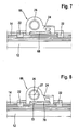
- a particularly simple embodiment results when the bottom part is bent between its ends towards the wiper rubber, so that in the middle region of the connecting element a reinforced surface pressure on the squeegee arises when the claws are bent around the support element or the support elements during assembly.
- the size and height of the curvature. largely determines the height of the local surface pressure.
- the bottom part in the region of a hinge axis has a transversely extending to the longitudinal direction bead, which is pressed in the mounted position in the squeegee.
- the bottom part may have at its ends jaws, which are bent during assembly in the direction of the squeegee and engage with their hooks in the squeegee.
- the hooks By the length and shape of the hook
- the jaws may be molded longitudinally at the ends of the bottom part or unlatched in the end parts in the bottom part. Both options result in only small additional costs in the production of the connection element.
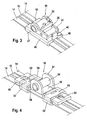
- a wiper blade 10 with a squeegee 12 has two spring rails 14, which serve as support elements and are inserted in lateral longitudinal grooves of the wiper blade rubber 12.
- a connection element 16 is mounted, which has a bottom part 18 and side walls 24 formed thereon.
- claws 22 are integrally formed on the longitudinal sides, which include the spring rails 14 on the protruding from the squeegee 12 parts.
- the side walls 24 are interconnected by a hinge hub 26 which forms a hinge with a hinge axis 27 with a hinge pin, not shown, of the wiper arm.
- a hinge hub 26 which forms a hinge with a hinge axis 27 with a hinge pin, not shown, of the wiper arm.
- the action of the hinge hub 26 and hinge pin can be reversed, so that the side walls 24 are connected together by a hinge pin and a hinge hub 26 is provided on the wiper arm.
- a clamping member 28 is pivotally mounted in the side parts 24 via bearing journals 30.
- the elevation of the cam 32 extends approximately perpendicular to the lever 34.
- the cam 32 moves through a window 20 in the bottom portion 18 against the squeegee 12 and is in this impressed.
- the height and shape of the cam 32 results in the locally increased surface pressure relative to the squeegee rubber 12.
- this In the end position of the lever 34, this is fixed.
- it has on its free end face a recess 36 in which two mutually opposite latching projections 38 are arranged. These cooperate with notches 40 which are arranged on a tab 42.
- the tab 42 is formed in extension of the bottom part 18 at this and angled in the direction of the side walls 24.
- connection element 44 after Fig. 3 differs from the connection element 16 after Fig. 1 and Fig. 2 in that it is made of die-cast or injection-molded, and that it has continuous claws 46 on both longitudinal sides.
- the connecting element 44 is pushed in the longitudinal direction onto the wiper blade 10 and fixed via the clamping part 28.
- the side walls 24 and the tab 48 and the bottom part 18 and the claws 46 are manufactured in a single manufacturing process.
- connection element 50 after Fig. 4 has a bottom part 56 which is formed at its ends as bridges 54, on which claws 52 are formed. Between the bridges 54 and the support elements 14 and the squeegee 12 clamping pieces 58 are provided which cooperate with wedges 60. These are based on the inside of the bridges 54 and press the clamping pieces 58 against the squeegee 12, whereby a local higher surface pressure arises.
- the wedges 60 are fixed in the longitudinal direction by pawls 64, which engage in the end position of the wedges 60 in locking holes 62 of the bridges 54.
- the design of the clamping pieces 58 and the wedges 60, the contact pressure against the squeegee 12 can be varied.
- the bottom part 70 has a transverse to the wiper blade 10 extending bead 72 in the region of the hinge axis 27. Compared to the execution according to Fig. 7 The contact forces concentrate in the execution Fig. 8 on the narrower area of the bead 72.
- connection elements 74 and 80 after Fig. 9 to Fig. 11 have on the bottom part 18 molded claws 76, 82. These are slightly angled before assembly, so that the connection elements 74, 80 can be pushed over the wiper blade 10 in the longitudinal direction. In the final position of the connection elements 74 ', 80, the claws 76, 82 are pressed against the squeegee 12, with their hooks 78, 84 engage the squeegee 12 and fix the connection elements 74, 80 in the longitudinal direction.
- connection element 74 differs from the connection element 80 in that the claws 76 point outward from the end faces of the bottom part 18 and each have two hooks 78 arranged in parallel, while the connection element 80 has a claw 82 with a hook 84 at each end which are disengaged from the bottom part 18 and point to the articulation hub 26. Due to the length and design of the hooks 78, 84, the local surface pressure to the squeegee 12 can be modified and the holding force can be adapted to the requirements.
Landscapes
- Engineering & Computer Science (AREA)
- Mechanical Engineering (AREA)
- Insertion Pins And Rivets (AREA)
- Wire Bonding (AREA)
- Moulds For Moulding Plastics Or The Like (AREA)
- Springs (AREA)
- Body Structure For Vehicles (AREA)
- Clamps And Clips (AREA)
- Connector Housings Or Holding Contact Members (AREA)
- Connection Of Plates (AREA)
- Vehicle Interior And Exterior Ornaments, Soundproofing, And Insulation (AREA)
- Pivots And Pivotal Connections (AREA)
- Ink Jet (AREA)
Claims (11)
- Elément de raccordement (16, 44, 50, 66, 74, 80) pour la connexion articulée d'un balai d'essuie-glace (10) qui possède en tant qu'élément porteur au moins un rail élastique (14), avec un bras d'essuie-glace, l'élément de raccordement (16, 44, 50, 66, 74, 80) présentant des griffes (22, 46, 52) qui sont façonnées latéralement sur une partie de fond (18) et qui, dans l'état monté, entourent et retiennent le rail élastique (14), en ce que la partie de fond (18) s'appuie contre une partie d'une raclette d'essuie-glace (12), qui est disposée entre le rail élastique (14) et la partie de fond (18, 56, 68, 70), caractérisé en ce que l'élément de raccordement (16, 44, 50, 66, 74, 80) présente des moyens supplémentaires (28, 58, 60, 68, 72, 76, 78, 82, 84), qui permettent d'augmenter localement la pression superficielle entre la partie de fond (18, 56, 68, 70) et la raclette d'essuie-glace (12).
- Elément de raccordement (16) selon la revendication 1, caractérisé en ce qu'une partie de serrage (28) avec un came (32) et un levier (34) est montée de manière pivotante dans des parois latérales (24) transversalement à la direction longitudinale de l'élément de raccordement (16), la came (32) pouvant être déplacée au moyen du levier (34) dans une position de blocage dans laquelle elle presse à travers une fenêtre (20) dans la partie de fond (18) contre la raclette d'essuie-glace (12), et le levier (34) est fixé dans cette position.
- Elément de raccordement (16) selon la revendication 2, caractérisé en ce que le levier (34) possède, sur son côté frontal libre, un évidement (36) dans lequel est prévue au moins une saillie d'encliquetage (38) ou une encoche (40), la saillie d'encliquetage (38) coopérant avec au moins une encoche (40) ou l'encoche (40) coopérant avec une saillie d'encliquetage (38) sur une patte (42) qui est façonnée sur la partie de fond (18).
- Elément de raccordement (44) selon l'une quelconque des revendications précédentes, caractérisé en ce qu'il s'agit d'une pièce moulée sous pression ou d'une pièce moulée par injection.
- Elément de raccordement (44) selon la revendication 3 ou 4, caractérisé en ce qu'il possède, sur les deux côtés longitudinaux, à chaque fois une griffe continue (46).
- Elément de raccordement (50) selon la revendication 1, caractérisé en ce que la partie de fond (56) forme sur ses extrémités des ponts (54) sur lesquels sont façonnées les griffes (52), des pièces de serrage (58) étant disposées entre les ponts (54) et la raclette d'essuie-glace (12), lesquelles sont pressées par des coins (60) contre la raclette d'essuie-glace (12).
- Elément de raccordement (50) selon la revendication 6, caractérisé en ce que les coins (60) présentent des cliquets (64) qui s'engagent dans leur position d'extrémité dans des trous d'encliquetage (62) dans les ponts (54).
- Elément de raccordement (66) selon la revendication 1, caractérisé en ce que la partie de fond (68) est cintrée entre ses extrémités vers la raclette d'essuie-glace (12), de sorte que dans la région centrale de l'élément de raccordement (66) ait lieu un pressage à plat renforcé contre la raclette d'essuie-glace (12).
- Elément de raccordement (66) selon la revendication 8, caractérisé en ce que la partie de fond (70) présente, dans la région d'un axe d'articulation (27), une moulure (72) s'étendant transversalement à la direction longitudinale, qui est enfoncée dans la raclette d'essuie-glace (12) dans la position montée.
- Elément de raccordement (74) selon la revendication 1, caractérisé en ce que la partie de fond (18) présente à ses extrémités des crampons (76) tournés vers l'extérieur, qui, lors du montage, sont cintrés dans la direction de la raclette d'essuie-glace (12) et viennent en prise avec leurs crochets (78) dans la raclette d'essuie-glace (12).
- Elément de raccordement (80) selon la revendication 1, caractérisé en ce que dans ses régions d'extrémité, dans la partie de fond (18), sont entaillés des crampons (82), qui, lors du montage, sont pressés contre la raclette d'essuie-glace (12), de sorte que leurs crochets (84) viennent en prise dans la raclette d'essuie-glace (12).
Priority Applications (1)
| Application Number | Priority Date | Filing Date | Title |
|---|---|---|---|
| PL06807687T PL1966013T3 (pl) | 2005-12-19 | 2006-10-31 | Element przyłączeniowy |
Applications Claiming Priority (2)
| Application Number | Priority Date | Filing Date | Title |
|---|---|---|---|
| DE102005060664A DE102005060664A1 (de) | 2005-12-19 | 2005-12-19 | Anschlusselement |
| PCT/EP2006/067969 WO2007071487A1 (fr) | 2005-12-19 | 2006-10-31 | Element de raccordement |
Publications (2)
| Publication Number | Publication Date |
|---|---|
| EP1966013A1 EP1966013A1 (fr) | 2008-09-10 |
| EP1966013B1 true EP1966013B1 (fr) | 2011-02-23 |
Family
ID=37667505
Family Applications (1)
| Application Number | Title | Priority Date | Filing Date |
|---|---|---|---|
| EP06807687A Not-in-force EP1966013B1 (fr) | 2005-12-19 | 2006-10-31 | Element de raccordement |
Country Status (11)
| Country | Link |
|---|---|
| US (1) | US8191201B2 (fr) |
| EP (1) | EP1966013B1 (fr) |
| JP (1) | JP4881394B2 (fr) |
| KR (1) | KR20080085832A (fr) |
| CN (1) | CN101341052A (fr) |
| AT (1) | ATE499250T1 (fr) |
| BR (1) | BRPI0620097A2 (fr) |
| DE (2) | DE102005060664A1 (fr) |
| ES (1) | ES2359868T3 (fr) |
| PL (1) | PL1966013T3 (fr) |
| WO (1) | WO2007071487A1 (fr) |
Families Citing this family (33)
| Publication number | Priority date | Publication date | Assignee | Title |
|---|---|---|---|---|
| DE102008000626A1 (de) * | 2008-03-12 | 2009-09-17 | Robert Bosch Gmbh | Vorrichtung zum gelenkigen Verbinden eines Wischblatts |
| US9085284B2 (en) * | 2008-09-23 | 2015-07-21 | Alberee Products, Inc. | Adapter for windshield wiper assembly |
| DE102008042839A1 (de) * | 2008-10-14 | 2010-04-15 | Robert Bosch Gmbh | Anschlusselement zum gelenkigen Verbinden eines Wischblatts in Flachbalkenbauweise mit einem Wischarm |
| DE102009000860A1 (de) * | 2009-02-13 | 2010-08-19 | Robert Bosch Gmbh | Wischblatt mit einer Adaptereinheit zur Befestigung an einem Wischraum |
| US20130227809A1 (en) | 2012-02-24 | 2013-09-05 | Pylon Manufacturing Corp. | Wiper blade |
| US8495787B2 (en) | 2010-08-03 | 2013-07-30 | Rally Manufacturing, Inc. | Windshield wiper |
| US9457768B2 (en) | 2011-04-21 | 2016-10-04 | Pylon Manufacturing Corp. | Vortex damping wiper blade |
| US9174609B2 (en) | 2011-04-21 | 2015-11-03 | Pylon Manufacturing Corp. | Wiper blade with cover |
| WO2013016493A1 (fr) | 2011-07-28 | 2013-01-31 | Pylon Manufacturing Corp. | Adaptateur, raccord et ensemble d'essuie-glace |
| US9108595B2 (en) | 2011-07-29 | 2015-08-18 | Pylon Manufacturing Corporation | Windshield wiper connector |
| US20130219649A1 (en) | 2012-02-24 | 2013-08-29 | Pylon Manufacturing Corp. | Wiper blade |
| DE102013203686A1 (de) * | 2012-05-29 | 2013-12-05 | Robert Bosch Gmbh | Wischblatt zum Reinigen von Scheiben insbesondere von Kraftfahrzeugen |
| US10829092B2 (en) | 2012-09-24 | 2020-11-10 | Pylon Manufacturing Corp. | Wiper blade with modular mounting base |
| US10166951B2 (en) | 2013-03-15 | 2019-01-01 | Pylon Manufacturing Corp. | Windshield wiper connector |
| US9555775B2 (en) | 2013-03-15 | 2017-01-31 | Illinois Tool Works Inc. | Connectors and connector kit for attachment of a windshield wiper blade to multiple types of windshield wiper arms |
| US9511748B2 (en) | 2013-03-15 | 2016-12-06 | Illinois Tool Works Inc. | Universal connector for attachment of a windshield wiper blade with multiple types of windshield wiper arms |
| DE112014004175T5 (de) | 2013-09-11 | 2016-05-25 | Asmo Co., Ltd. | Wischerblatt und Verfahren zur Herstellung des Wischerblatts |
| USD727238S1 (en) | 2013-12-13 | 2015-04-21 | Illinois Tool Works Inc. | Cover used for windshield wiper connectors |
| US9505380B2 (en) | 2014-03-07 | 2016-11-29 | Pylon Manufacturing Corp. | Windshield wiper connector and assembly |
| US9434355B2 (en) | 2014-04-01 | 2016-09-06 | Trico Products Corporation | Wiper adapter and wiper assembly incorporating the same |
| US9539987B2 (en) | 2014-04-01 | 2017-01-10 | Trico Products Corporation | Wiper adapter and wiper assembly incorporating the same |
| USD777079S1 (en) | 2014-10-03 | 2017-01-24 | Pylon Manufacturing Corp. | Wiper blade frame |
| EP3368383B1 (fr) | 2015-10-26 | 2021-08-04 | Pylon Manufacturing Corp. | Balai d'essuie-glace |
| US11014539B2 (en) * | 2015-11-02 | 2021-05-25 | Trico Products Corporation | Refillable wiper blade with refill subassembly |
| US10717414B2 (en) | 2016-05-19 | 2020-07-21 | Pylon Manufacturing Corporation | Windshield wiper blade |
| US11040705B2 (en) | 2016-05-19 | 2021-06-22 | Pylon Manufacturing Corp. | Windshield wiper connector |
| AU2017268008A1 (en) | 2016-05-19 | 2018-11-22 | Pylon Manufacturing Corp. | Windshield wiper connector |
| AU2017268019A1 (en) | 2016-05-19 | 2018-11-22 | Pylon Manufacturing Corp. | Windshield wiper connector |
| AU2017267978A1 (en) | 2016-05-19 | 2018-11-22 | Pylon Manufacturing Corp. | Windshield wiper connector |
| WO2018081791A1 (fr) | 2016-10-31 | 2018-05-03 | Pylon Manufacturing Corp. | Balai d'essuie-glace pourvu d'une coiffe |
| KR102200331B1 (ko) * | 2019-05-02 | 2021-01-07 | 구성회 | 레이스 웨이 연결장치 |
| KR102407709B1 (ko) * | 2020-05-18 | 2022-06-10 | 임춘옥 | 레이스웨이 조립체 |
| KR102501261B1 (ko) * | 2020-09-29 | 2023-02-17 | 김중영 | 레이스 웨이 연결장치 |
Family Cites Families (11)
| Publication number | Priority date | Publication date | Assignee | Title |
|---|---|---|---|---|
| US5615851A (en) | 1995-11-06 | 1997-04-01 | Yazaki Corporation | Wire harness attachment clip |
| DE19835065A1 (de) | 1998-08-04 | 2000-02-10 | Bosch Gmbh Robert | Wischblatt für Scheiben von Kraftfahrzeugen |
| DE10025710A1 (de) | 2000-02-23 | 2001-08-30 | Bosch Gmbh Robert | Wischblatt für Scheiben insbesondere von Kraftfahrzeugen |
| DE10057253A1 (de) | 2000-11-18 | 2002-05-23 | Bosch Gmbh Robert | Top-Lock-Verbindung Gelenkfreies WBA |
| DE10259670A1 (de) | 2002-12-18 | 2004-07-01 | Robert Bosch Gmbh | Verbindungsanordnung einer Wischvorrichtung für Scheiben von Kraftfahrzeugen |
| DE10322058B4 (de) | 2003-05-15 | 2017-03-23 | Robert Bosch Gmbh | Wischblatt |
| DE20308234U1 (de) | 2003-05-27 | 2003-08-21 | Schwarz Verbindungssysteme GmbH, 75382 Althengstett | Anordnung zur Aufnahme eines lösbar verriegelbaren Einschub-Elementes |
| JP4267537B2 (ja) | 2004-03-18 | 2009-05-27 | アスモ株式会社 | ワイパブレード |
| DE102004017941A1 (de) | 2004-04-14 | 2005-11-03 | Robert Bosch Gmbh | Vorrichtung zum Verbinden eines Wischblatts mit einem Wischerarm |
| DE102004019157A1 (de) | 2004-04-21 | 2005-11-10 | Robert Bosch Gmbh | Wischblatt |
| DE202005012619U1 (de) | 2005-08-08 | 2005-10-20 | Lin, Chin-Lien | Scheibenwischer |
-
2005
- 2005-12-19 DE DE102005060664A patent/DE102005060664A1/de not_active Withdrawn
-
2006
- 2006-10-31 EP EP06807687A patent/EP1966013B1/fr not_active Not-in-force
- 2006-10-31 PL PL06807687T patent/PL1966013T3/pl unknown
- 2006-10-31 JP JP2008546308A patent/JP4881394B2/ja not_active Expired - Fee Related
- 2006-10-31 WO PCT/EP2006/067969 patent/WO2007071487A1/fr active Application Filing
- 2006-10-31 CN CNA2006800478750A patent/CN101341052A/zh active Pending
- 2006-10-31 ES ES06807687T patent/ES2359868T3/es active Active
- 2006-10-31 US US12/097,990 patent/US8191201B2/en not_active Expired - Fee Related
- 2006-10-31 BR BRPI0620097-4A patent/BRPI0620097A2/pt not_active IP Right Cessation
- 2006-10-31 DE DE502006008963T patent/DE502006008963D1/de active Active
- 2006-10-31 AT AT06807687T patent/ATE499250T1/de active
- 2006-10-31 KR KR1020087013964A patent/KR20080085832A/ko not_active Application Discontinuation
Also Published As
| Publication number | Publication date |
|---|---|
| PL1966013T3 (pl) | 2011-07-29 |
| US20080313841A1 (en) | 2008-12-25 |
| JP4881394B2 (ja) | 2012-02-22 |
| ES2359868T3 (es) | 2011-05-27 |
| ATE499250T1 (de) | 2011-03-15 |
| KR20080085832A (ko) | 2008-09-24 |
| CN101341052A (zh) | 2009-01-07 |
| EP1966013A1 (fr) | 2008-09-10 |
| DE102005060664A1 (de) | 2007-06-21 |
| WO2007071487A1 (fr) | 2007-06-28 |
| JP2009519857A (ja) | 2009-05-21 |
| US8191201B2 (en) | 2012-06-05 |
| BRPI0620097A2 (pt) | 2011-11-01 |
| DE502006008963D1 (de) | 2011-04-07 |
Similar Documents
| Publication | Publication Date | Title |
|---|---|---|
| EP1966013B1 (fr) | Element de raccordement | |
| EP2326538B1 (fr) | Dispositif de raccordement permettant de realiser une liaison articulee entre un balai d'essuie-glace et un bras d'essuie-glace | |
| EP2040960B1 (fr) | Élément de raccordement pour un balai d'essuie-glace et essuie-glace | |
| EP2321160B1 (fr) | Dispositif de liaison articulée entre un balai d essuie-glace et un bras d essuie-glace | |
| EP1753646B1 (fr) | Balai d'essuie-glace | |
| DE102007022185B4 (de) | Verbindungselement zum gelenkigen Verbinden eines Wischblatts mit einem Wischarm | |
| EP2259954B1 (fr) | Raclette d essuie-glace | |
| EP2190703B1 (fr) | Balai d'essuie-glace | |
| DE60112047T2 (de) | Scheibenwischervorrichtung | |
| DE112011103907B4 (de) | Flachbalken-Scheibenwischeranordnung mit selbstverriegelnder Endkappe | |
| DE102005016485A1 (de) | Vorrichtung zum gelenkigen Verbinden eines Wischblatts mit einem Wischarm eines Scheibenwischers | |
| EP2315687A1 (fr) | Balai d essuie-glace avec un élément de raccord | |
| DE102007016479A1 (de) | Anschlussvorrichtung | |
| DE102006059077A1 (de) | Wischblatt | |
| EP2331373B1 (fr) | Dispositif d'assemblage pour la liaison articulée d'un balai d'essuie-glace | |
| WO2012079851A1 (fr) | Dispositif d'essuie-glace | |
| EP2097298B1 (fr) | Balai d'essuie-glace | |
| DE10305322B4 (de) | Wischblatt | |
| DE3423317A1 (de) | Wischvorrichtung fuer scheiben von kraftfahrzeugen | |
| WO2009056385A1 (fr) | Balai d'essuie-glace | |
| DE102015215706A1 (de) | Wischblattadapter |
Legal Events
| Date | Code | Title | Description |
|---|---|---|---|
| PUAI | Public reference made under article 153(3) epc to a published international application that has entered the european phase |
Free format text: ORIGINAL CODE: 0009012 |
|
| 17P | Request for examination filed |
Effective date: 20080721 |
|
| AK | Designated contracting states |
Kind code of ref document: A1 Designated state(s): AT BE BG CH CY CZ DE DK EE ES FI FR GB GR HU IE IS IT LI LT LU LV MC NL PL PT RO SE SI SK TR |
|
| 17Q | First examination report despatched |
Effective date: 20090817 |
|
| GRAP | Despatch of communication of intention to grant a patent |
Free format text: ORIGINAL CODE: EPIDOSNIGR1 |
|
| DAX | Request for extension of the european patent (deleted) | ||
| GRAS | Grant fee paid |
Free format text: ORIGINAL CODE: EPIDOSNIGR3 |
|
| GRAA | (expected) grant |
Free format text: ORIGINAL CODE: 0009210 |
|
| AK | Designated contracting states |
Kind code of ref document: B1 Designated state(s): AT BE BG CH CY CZ DE DK EE ES FI FR GB GR HU IE IS IT LI LT LU LV MC NL PL PT RO SE SI SK TR |
|
| REG | Reference to a national code |
Ref country code: GB Ref legal event code: FG4D Free format text: NOT ENGLISH |
|
| REG | Reference to a national code |
Ref country code: CH Ref legal event code: EP |
|
| REG | Reference to a national code |
Ref country code: IE Ref legal event code: FG4D Free format text: LANGUAGE OF EP DOCUMENT: GERMAN |
|
| REF | Corresponds to: |
Ref document number: 502006008963 Country of ref document: DE Date of ref document: 20110407 Kind code of ref document: P |
|
| REG | Reference to a national code |
Ref country code: DE Ref legal event code: R096 Ref document number: 502006008963 Country of ref document: DE Effective date: 20110407 |
|
| REG | Reference to a national code |
Ref country code: ES Ref legal event code: FG2A Ref document number: 2359868 Country of ref document: ES Kind code of ref document: T3 Effective date: 20110527 |
|
| REG | Reference to a national code |
Ref country code: NL Ref legal event code: T3 |
|
| LTIE | Lt: invalidation of european patent or patent extension |
Effective date: 20110223 |
|
| PG25 | Lapsed in a contracting state [announced via postgrant information from national office to epo] |
Ref country code: SE Free format text: LAPSE BECAUSE OF FAILURE TO SUBMIT A TRANSLATION OF THE DESCRIPTION OR TO PAY THE FEE WITHIN THE PRESCRIBED TIME-LIMIT Effective date: 20110223 Ref country code: GR Free format text: LAPSE BECAUSE OF FAILURE TO SUBMIT A TRANSLATION OF THE DESCRIPTION OR TO PAY THE FEE WITHIN THE PRESCRIBED TIME-LIMIT Effective date: 20110524 Ref country code: PT Free format text: LAPSE BECAUSE OF FAILURE TO SUBMIT A TRANSLATION OF THE DESCRIPTION OR TO PAY THE FEE WITHIN THE PRESCRIBED TIME-LIMIT Effective date: 20110623 Ref country code: LT Free format text: LAPSE BECAUSE OF FAILURE TO SUBMIT A TRANSLATION OF THE DESCRIPTION OR TO PAY THE FEE WITHIN THE PRESCRIBED TIME-LIMIT Effective date: 20110223 Ref country code: LV Free format text: LAPSE BECAUSE OF FAILURE TO SUBMIT A TRANSLATION OF THE DESCRIPTION OR TO PAY THE FEE WITHIN THE PRESCRIBED TIME-LIMIT Effective date: 20110223 |
|
| REG | Reference to a national code |
Ref country code: PL Ref legal event code: T3 |
|
| PG25 | Lapsed in a contracting state [announced via postgrant information from national office to epo] |
Ref country code: FI Free format text: LAPSE BECAUSE OF FAILURE TO SUBMIT A TRANSLATION OF THE DESCRIPTION OR TO PAY THE FEE WITHIN THE PRESCRIBED TIME-LIMIT Effective date: 20110223 Ref country code: SI Free format text: LAPSE BECAUSE OF FAILURE TO SUBMIT A TRANSLATION OF THE DESCRIPTION OR TO PAY THE FEE WITHIN THE PRESCRIBED TIME-LIMIT Effective date: 20110223 Ref country code: BG Free format text: LAPSE BECAUSE OF FAILURE TO SUBMIT A TRANSLATION OF THE DESCRIPTION OR TO PAY THE FEE WITHIN THE PRESCRIBED TIME-LIMIT Effective date: 20110523 Ref country code: CY Free format text: LAPSE BECAUSE OF FAILURE TO SUBMIT A TRANSLATION OF THE DESCRIPTION OR TO PAY THE FEE WITHIN THE PRESCRIBED TIME-LIMIT Effective date: 20110223 |
|
| REG | Reference to a national code |
Ref country code: IE Ref legal event code: FD4D |
|
| PG25 | Lapsed in a contracting state [announced via postgrant information from national office to epo] |
Ref country code: EE Free format text: LAPSE BECAUSE OF FAILURE TO SUBMIT A TRANSLATION OF THE DESCRIPTION OR TO PAY THE FEE WITHIN THE PRESCRIBED TIME-LIMIT Effective date: 20110223 Ref country code: IE Free format text: LAPSE BECAUSE OF FAILURE TO SUBMIT A TRANSLATION OF THE DESCRIPTION OR TO PAY THE FEE WITHIN THE PRESCRIBED TIME-LIMIT Effective date: 20110223 Ref country code: DK Free format text: LAPSE BECAUSE OF FAILURE TO SUBMIT A TRANSLATION OF THE DESCRIPTION OR TO PAY THE FEE WITHIN THE PRESCRIBED TIME-LIMIT Effective date: 20110223 |
|
| PG25 | Lapsed in a contracting state [announced via postgrant information from national office to epo] |
Ref country code: RO Free format text: LAPSE BECAUSE OF FAILURE TO SUBMIT A TRANSLATION OF THE DESCRIPTION OR TO PAY THE FEE WITHIN THE PRESCRIBED TIME-LIMIT Effective date: 20110223 Ref country code: SK Free format text: LAPSE BECAUSE OF FAILURE TO SUBMIT A TRANSLATION OF THE DESCRIPTION OR TO PAY THE FEE WITHIN THE PRESCRIBED TIME-LIMIT Effective date: 20110223 |
|
| PLBE | No opposition filed within time limit |
Free format text: ORIGINAL CODE: 0009261 |
|
| STAA | Information on the status of an ep patent application or granted ep patent |
Free format text: STATUS: NO OPPOSITION FILED WITHIN TIME LIMIT |
|
| 26N | No opposition filed |
Effective date: 20111124 |
|
| REG | Reference to a national code |
Ref country code: DE Ref legal event code: R097 Ref document number: 502006008963 Country of ref document: DE Effective date: 20111124 |
|
| PG25 | Lapsed in a contracting state [announced via postgrant information from national office to epo] |
Ref country code: IT Free format text: LAPSE BECAUSE OF FAILURE TO SUBMIT A TRANSLATION OF THE DESCRIPTION OR TO PAY THE FEE WITHIN THE PRESCRIBED TIME-LIMIT Effective date: 20110223 Ref country code: MC Free format text: LAPSE BECAUSE OF NON-PAYMENT OF DUE FEES Effective date: 20111031 |
|
| REG | Reference to a national code |
Ref country code: CH Ref legal event code: PL |
|
| PG25 | Lapsed in a contracting state [announced via postgrant information from national office to epo] |
Ref country code: LI Free format text: LAPSE BECAUSE OF NON-PAYMENT OF DUE FEES Effective date: 20111031 Ref country code: CH Free format text: LAPSE BECAUSE OF NON-PAYMENT OF DUE FEES Effective date: 20111031 |
|
| REG | Reference to a national code |
Ref country code: AT Ref legal event code: MM01 Ref document number: 499250 Country of ref document: AT Kind code of ref document: T Effective date: 20111031 |
|
| PG25 | Lapsed in a contracting state [announced via postgrant information from national office to epo] |
Ref country code: AT Free format text: LAPSE BECAUSE OF NON-PAYMENT OF DUE FEES Effective date: 20111031 |
|
| PGFP | Annual fee paid to national office [announced via postgrant information from national office to epo] |
Ref country code: BE Payment date: 20121022 Year of fee payment: 7 Ref country code: CZ Payment date: 20121022 Year of fee payment: 7 Ref country code: FR Payment date: 20121113 Year of fee payment: 7 |
|
| PGFP | Annual fee paid to national office [announced via postgrant information from national office to epo] |
Ref country code: ES Payment date: 20121023 Year of fee payment: 7 Ref country code: PL Payment date: 20121019 Year of fee payment: 7 Ref country code: GB Payment date: 20121023 Year of fee payment: 7 |
|
| PGFP | Annual fee paid to national office [announced via postgrant information from national office to epo] |
Ref country code: NL Payment date: 20121018 Year of fee payment: 7 |
|
| PG25 | Lapsed in a contracting state [announced via postgrant information from national office to epo] |
Ref country code: LU Free format text: LAPSE BECAUSE OF NON-PAYMENT OF DUE FEES Effective date: 20111031 |
|
| PG25 | Lapsed in a contracting state [announced via postgrant information from national office to epo] |
Ref country code: IS Free format text: LAPSE BECAUSE OF FAILURE TO SUBMIT A TRANSLATION OF THE DESCRIPTION OR TO PAY THE FEE WITHIN THE PRESCRIBED TIME-LIMIT Effective date: 20110223 |
|
| PG25 | Lapsed in a contracting state [announced via postgrant information from national office to epo] |
Ref country code: TR Free format text: LAPSE BECAUSE OF FAILURE TO SUBMIT A TRANSLATION OF THE DESCRIPTION OR TO PAY THE FEE WITHIN THE PRESCRIBED TIME-LIMIT Effective date: 20110223 |
|
| PG25 | Lapsed in a contracting state [announced via postgrant information from national office to epo] |
Ref country code: HU Free format text: LAPSE BECAUSE OF FAILURE TO SUBMIT A TRANSLATION OF THE DESCRIPTION OR TO PAY THE FEE WITHIN THE PRESCRIBED TIME-LIMIT Effective date: 20110223 |
|
| BERE | Be: lapsed |
Owner name: ROBERT BOSCH G.M.B.H. Effective date: 20131031 |
|
| REG | Reference to a national code |
Ref country code: NL Ref legal event code: V1 Effective date: 20140501 |
|
| GBPC | Gb: european patent ceased through non-payment of renewal fee |
Effective date: 20131031 |
|
| PG25 | Lapsed in a contracting state [announced via postgrant information from national office to epo] |
Ref country code: GB Free format text: LAPSE BECAUSE OF NON-PAYMENT OF DUE FEES Effective date: 20131031 |
|
| REG | Reference to a national code |
Ref country code: FR Ref legal event code: ST Effective date: 20140630 |
|
| PG25 | Lapsed in a contracting state [announced via postgrant information from national office to epo] |
Ref country code: NL Free format text: LAPSE BECAUSE OF NON-PAYMENT OF DUE FEES Effective date: 20140501 Ref country code: CZ Free format text: LAPSE BECAUSE OF NON-PAYMENT OF DUE FEES Effective date: 20131031 Ref country code: FR Free format text: LAPSE BECAUSE OF NON-PAYMENT OF DUE FEES Effective date: 20131031 |
|
| PG25 | Lapsed in a contracting state [announced via postgrant information from national office to epo] |
Ref country code: BE Free format text: LAPSE BECAUSE OF NON-PAYMENT OF DUE FEES Effective date: 20131031 |
|
| REG | Reference to a national code |
Ref country code: ES Ref legal event code: FD2A Effective date: 20141107 |
|
| PG25 | Lapsed in a contracting state [announced via postgrant information from national office to epo] |
Ref country code: ES Free format text: LAPSE BECAUSE OF NON-PAYMENT OF DUE FEES Effective date: 20131101 |
|
| REG | Reference to a national code |
Ref country code: PL Ref legal event code: LAPE |
|
| PG25 | Lapsed in a contracting state [announced via postgrant information from national office to epo] |
Ref country code: PL Free format text: LAPSE BECAUSE OF NON-PAYMENT OF DUE FEES Effective date: 20131031 |
|
| PGFP | Annual fee paid to national office [announced via postgrant information from national office to epo] |
Ref country code: DE Payment date: 20201214 Year of fee payment: 15 |
|
| REG | Reference to a national code |
Ref country code: DE Ref legal event code: R119 Ref document number: 502006008963 Country of ref document: DE |
|
| PG25 | Lapsed in a contracting state [announced via postgrant information from national office to epo] |
Ref country code: DE Free format text: LAPSE BECAUSE OF NON-PAYMENT OF DUE FEES Effective date: 20220503 |