US9511748B2 - Universal connector for attachment of a windshield wiper blade with multiple types of windshield wiper arms - Google Patents
Universal connector for attachment of a windshield wiper blade with multiple types of windshield wiper arms Download PDFInfo
- Publication number
- US9511748B2 US9511748B2 US13/836,333 US201313836333A US9511748B2 US 9511748 B2 US9511748 B2 US 9511748B2 US 201313836333 A US201313836333 A US 201313836333A US 9511748 B2 US9511748 B2 US 9511748B2
- Authority
- US
- United States
- Prior art keywords
- wiper arm
- wiper
- connector
- receiving element
- support
- Prior art date
- Legal status (The legal status is an assumption and is not a legal conclusion. Google has not performed a legal analysis and makes no representation as to the accuracy of the status listed.)
- Active, expires
Links
Images


Classifications
-
- B—PERFORMING OPERATIONS; TRANSPORTING
- B60—VEHICLES IN GENERAL
- B60S—SERVICING, CLEANING, REPAIRING, SUPPORTING, LIFTING, OR MANOEUVRING OF VEHICLES, NOT OTHERWISE PROVIDED FOR
- B60S1/00—Cleaning of vehicles
- B60S1/02—Cleaning windscreens, windows or optical devices
- B60S1/04—Wipers or the like, e.g. scrapers
- B60S1/32—Wipers or the like, e.g. scrapers characterised by constructional features of wiper blade arms or blades
- B60S1/40—Connections between blades and arms
- B60S1/4003—Multi-purpose connections for two or more kinds of arm ends
-
- B—PERFORMING OPERATIONS; TRANSPORTING
- B60—VEHICLES IN GENERAL
- B60S—SERVICING, CLEANING, REPAIRING, SUPPORTING, LIFTING, OR MANOEUVRING OF VEHICLES, NOT OTHERWISE PROVIDED FOR
- B60S1/00—Cleaning of vehicles
- B60S1/02—Cleaning windscreens, windows or optical devices
- B60S1/04—Wipers or the like, e.g. scrapers
- B60S1/32—Wipers or the like, e.g. scrapers characterised by constructional features of wiper blade arms or blades
- B60S1/40—Connections between blades and arms
- B60S1/4038—Connections between blades and arms for arms provided with a channel-shaped end
- B60S1/4045—Connections between blades and arms for arms provided with a channel-shaped end comprising a detachable intermediate element mounted on the channel-shaped end
- B60S1/4048—Connections between blades and arms for arms provided with a channel-shaped end comprising a detachable intermediate element mounted on the channel-shaped end the element being provided with retention means co-operating with the channel-shaped end of the arm
-
- B—PERFORMING OPERATIONS; TRANSPORTING
- B60—VEHICLES IN GENERAL
- B60S—SERVICING, CLEANING, REPAIRING, SUPPORTING, LIFTING, OR MANOEUVRING OF VEHICLES, NOT OTHERWISE PROVIDED FOR
- B60S1/00—Cleaning of vehicles
- B60S1/02—Cleaning windscreens, windows or optical devices
- B60S1/04—Wipers or the like, e.g. scrapers
- B60S1/32—Wipers or the like, e.g. scrapers characterised by constructional features of wiper blade arms or blades
- B60S1/40—Connections between blades and arms
- B60S1/4067—Connections between blades and arms for arms provided with a side pin
- B60S1/4074—Connections between blades and arms for arms provided with a side pin with means provided on the blade for locking the side pin
-
- B—PERFORMING OPERATIONS; TRANSPORTING
- B60—VEHICLES IN GENERAL
- B60S—SERVICING, CLEANING, REPAIRING, SUPPORTING, LIFTING, OR MANOEUVRING OF VEHICLES, NOT OTHERWISE PROVIDED FOR
- B60S1/00—Cleaning of vehicles
- B60S1/02—Cleaning windscreens, windows or optical devices
- B60S1/04—Wipers or the like, e.g. scrapers
- B60S1/32—Wipers or the like, e.g. scrapers characterised by constructional features of wiper blade arms or blades
- B60S1/40—Connections between blades and arms
- B60S1/4006—Connections between blades and arms for arms provided with a hook-shaped end
- B60S1/4009—Connections between blades and arms for arms provided with a hook-shaped end comprising a detachable intermediate element mounted on the hook-shaped end
- B60S2001/4032—Connections between blades and arms for arms provided with a hook-shaped end comprising a detachable intermediate element mounted on the hook-shaped end the element being able to receive arms with hooks of different radiuses
-
- B—PERFORMING OPERATIONS; TRANSPORTING
- B60—VEHICLES IN GENERAL
- B60S—SERVICING, CLEANING, REPAIRING, SUPPORTING, LIFTING, OR MANOEUVRING OF VEHICLES, NOT OTHERWISE PROVIDED FOR
- B60S1/00—Cleaning of vehicles
- B60S1/02—Cleaning windscreens, windows or optical devices
- B60S1/04—Wipers or the like, e.g. scrapers
- B60S1/32—Wipers or the like, e.g. scrapers characterised by constructional features of wiper blade arms or blades
- B60S1/40—Connections between blades and arms
- B60S1/4006—Connections between blades and arms for arms provided with a hook-shaped end
- B60S2001/4035—Connections between blades and arms for arms provided with a hook-shaped end the connection being covered by a removable cover mounted on the blade
-
- B—PERFORMING OPERATIONS; TRANSPORTING
- B60—VEHICLES IN GENERAL
- B60S—SERVICING, CLEANING, REPAIRING, SUPPORTING, LIFTING, OR MANOEUVRING OF VEHICLES, NOT OTHERWISE PROVIDED FOR
- B60S1/00—Cleaning of vehicles
- B60S1/02—Cleaning windscreens, windows or optical devices
- B60S1/04—Wipers or the like, e.g. scrapers
- B60S1/32—Wipers or the like, e.g. scrapers characterised by constructional features of wiper blade arms or blades
- B60S1/40—Connections between blades and arms
- B60S1/4038—Connections between blades and arms for arms provided with a channel-shaped end
- B60S1/4045—Connections between blades and arms for arms provided with a channel-shaped end comprising a detachable intermediate element mounted on the channel-shaped end
- B60S1/4048—Connections between blades and arms for arms provided with a channel-shaped end comprising a detachable intermediate element mounted on the channel-shaped end the element being provided with retention means co-operating with the channel-shaped end of the arm
- B60S2001/4051—Connections between blades and arms for arms provided with a channel-shaped end comprising a detachable intermediate element mounted on the channel-shaped end the element being provided with retention means co-operating with the channel-shaped end of the arm the intermediate element engaging the side walls of the arm
-
- B—PERFORMING OPERATIONS; TRANSPORTING
- B60—VEHICLES IN GENERAL
- B60S—SERVICING, CLEANING, REPAIRING, SUPPORTING, LIFTING, OR MANOEUVRING OF VEHICLES, NOT OTHERWISE PROVIDED FOR
- B60S1/00—Cleaning of vehicles
- B60S1/02—Cleaning windscreens, windows or optical devices
- B60S1/04—Wipers or the like, e.g. scrapers
- B60S1/32—Wipers or the like, e.g. scrapers characterised by constructional features of wiper blade arms or blades
- B60S1/40—Connections between blades and arms
- B60S1/4038—Connections between blades and arms for arms provided with a channel-shaped end
- B60S1/4045—Connections between blades and arms for arms provided with a channel-shaped end comprising a detachable intermediate element mounted on the channel-shaped end
- B60S1/4048—Connections between blades and arms for arms provided with a channel-shaped end comprising a detachable intermediate element mounted on the channel-shaped end the element being provided with retention means co-operating with the channel-shaped end of the arm
- B60S2001/4054—Connections between blades and arms for arms provided with a channel-shaped end comprising a detachable intermediate element mounted on the channel-shaped end the element being provided with retention means co-operating with the channel-shaped end of the arm the intermediate element engaging the back part of the arm
-
- B—PERFORMING OPERATIONS; TRANSPORTING
- B60—VEHICLES IN GENERAL
- B60S—SERVICING, CLEANING, REPAIRING, SUPPORTING, LIFTING, OR MANOEUVRING OF VEHICLES, NOT OTHERWISE PROVIDED FOR
- B60S1/00—Cleaning of vehicles
- B60S1/02—Cleaning windscreens, windows or optical devices
- B60S1/04—Wipers or the like, e.g. scrapers
- B60S1/32—Wipers or the like, e.g. scrapers characterised by constructional features of wiper blade arms or blades
- B60S1/40—Connections between blades and arms
- B60S1/4067—Connections between blades and arms for arms provided with a side pin
- B60S1/4077—Connections between blades and arms for arms provided with a side pin characterised by the connecting part of, or an intermediate element mounted on, the wiper blade
- B60S2001/408—Connections between blades and arms for arms provided with a side pin characterised by the connecting part of, or an intermediate element mounted on, the wiper blade the connecting part or the intermediate element being provided with holes for different diameters of pivoting pin
Definitions
- the present invention relates to a universal connector for attachment of a windshield wiper blade with multiple types of windshield wiper arms.
- One aspect of the present invention regards a connector for connecting a wiper blade and multiple types of wiper arms, the connector including a base for attachment to a wiper blade.
- the connector further includes a receiving element attached to the base, the receiving element having a structure to receive and be connected to at least six different wiper arms.
- a second aspect of the present invention regards a windshield wiper that includes a wiper blade, a wiper arm and a connector.
- the connector includes a base attached to the wiper blade and a receiving element attached to the base and the wiper arm.
- the receiving element has a structure to receive and be connected to at least five different wiper arms besides the wiper arm to which the receiving element is connected.
- a third aspect of the present invention regards a connector for connecting a wiper blade and a wiper arm.
- the connector includes a base for attachment to a wiper blade and a receiving element pivotably attached to the base.
- the receiving element includes an attachment that pivotably couples the receiving element to the base and a recess structured to receive a wiper arm.
- the connector further including a pivot stop that is positioned adjacent to the recess, wherein when the wiper arm is received by the recess, the pivot stop engages the wiper arm and prevents the receiving element from pivoting relative to the base.
- a fourth aspect of the present invention regards a windshield wiper that includes a wiper blade, a wiper arm and a connector.
- the connector includes a base for attachment to the wiper blade and a receiving element pivotably attached to the base.
- the receiving element includes an attachment that pivotably couples the receiving element to the base and a recess structured to receive the wiper arm.
- the connector further includes a pivot stop that is positioned adjacent to the recess, wherein when the wiper arm is received by the recess, the pivot stop engages the wiper arm and prevents the receiving element from pivoting relative to the base.
- a fifth aspect of the invention regards a connector for connecting a wiper blade and a wiper arm.
- the connector includes a base for attachment to a wiper blade and a receiving element attached to the base.
- the receiving element includes a support surface and an engagement surface spaced from and facing the support surface.
- the engagement surface and the support surface define a slot dimensioned to snugly receive a surface of a wiper arm.
- the engagement surface includes a first side support, a second side support that faces the first side support, and an engagement tongue.
- one end of the engagement tongue is attached to both the first side support and the second side support and an opposite end of the engagement tongue is unattached and has a protrusion that faces the support surface.
- a sixth aspect of the present invention regards a windshield wiper that includes a wiper blade, a wiper arm, and a connector.
- the connector includes both a base for attachment to the wiper blade and a receiving element attached to the base.
- the receiving element including a support surface and an engagement surface spaced from and facing the support surface, wherein the engagement surface and the support surface define a slot dimensioned to snugly receive a surface of the wiper arm.
- the engagement surface includes a first side support, a second side support that faces the first side support, and an engagement tongue.
- one end of the engagement tongue is attached to both the first side support and the second side support and an opposite end of the engagement tongue is unattached and has a protrusion that faces the support surface and engages the wiper arm.
- a seventh aspect of the present invention regards a connector for connecting a wiper blade and a wiper arm.
- the connector includes a base for attachment to a wiper blade and a receiving element pivotably attached to the base.
- the receiving element includes an attachment that pivotably couples the receiving element to the base, and a recess structured to receive a first wiper arm.
- the connector further includes a pivot stop that is positioned adjacent to the recess, wherein when the first wiper arm is received by the recess, the pivot stop engages the first wiper arm and prevents the receiving element from pivoting relative to the base.
- the connector further including a support surface having a pair of flexible wing stops that face one another and can be pressed towards one another, and an engagement surface spaced from and facing the support surface.
- the engagement surface and the support surface define a slot dimensioned to snugly receive a surface of a second wiper arm.
- the engagement surface includes a first side support, a second side support that faces the first side support, and an engagement tongue.
- one end of the engagement tongue is attached to both the first side support and the second side support and an opposite end of the engagement tongue is unattached and has a protrusion that faces the support surface.
- An eighth aspect of the present invention regards a windshield wiper that includes a wiper blade, a wiper arm and a connector.
- the connector is attached to the wiper arm and includes a base attached to the wiper blade and a receiving element pivotably attached to the base.
- the receiving element includes an attachment that pivotably couples the receiving element to the base and a recess structured to receive a first wiper arm.
- the connector further includes a pivot stop that is positioned adjacent to the recess, wherein when the first wiper arm is received by the recess, the pivot stop engages the first wiper arm and prevents the receiving element from pivoting relative to the base.
- the connector further including a support surface having a pair of flexible wing stops that face one another and can be pressed towards one another, and an engagement surface spaced from and facing the support surface.
- the flexible engagement surface and the support surface define a slot dimensioned to snugly receive a surface of a second wiper arm.
- the engagement surface includes a first side support, a second side support that faces the first side support, and an engagement tongue.
- one end of the engagement tongue is attached to both the first side support and the second side support and an opposite end of the engagement tongue is unattached and has a protrusion that faces the support surface.
- One or more aspects of the present invention provide the advantage of providing the possibility of attaching a wiper blade to multiple wiper arms by using just a single connector.
- One or more aspects of the present invention provide the advantage of providing the possibility of attaching a wiper blade to multiple wiper arms with a connector of a single piece construction.
- FIG. 1A shows a perspective view of an embodiment of a connector for connecting a wiper blade and multiple types of wiper arms, wherein the cap is opened;
- FIG. 1B shows a perspective view of the connector of FIG. 1A when the cap is closed
- FIG. 1C shows an exploded view of the connector of FIG. 1A ;
- FIG. 2 shows a left side view of the connector of FIG. 1B ;
- FIG. 3 shows a right side view of the connector of FIG. 1B ;
- FIG. 4 shows a top view of the connector of FIG. 1B ;
- FIG. 5 shows a bottom view of the connector of FIG. 1B ;
- FIG. 6 shows a front view of the connector of FIG. 1B ;
- FIG. 7 shows a rear view of the connector of FIG. 1B ;
- FIGS. 8A-D show three possible classes of connectors of wiper arms that can be attached to the connector of FIGS. 1A-C ;
- FIGS. 9A-B show a possible way of attaching a pin wiper arm to the connector of FIGS. 1A-C ;
- FIGS. 10A-C show a possible way of attaching a type of channel wiper arm, commonly known as a push tab button (PTB) wiper arm, to the connector of FIGS. 1A-C ;
- PTB push tab button
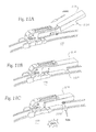
- FIGS. 11A-C show a possible way of attaching a type of channel wiper arm, commonly known as an insert & lock (I & L) wiper arm, to the connector of FIGS. 1A-C ;
- I & L insert & lock
- FIGS. 12A-B show a possible way of attaching a J-hook wiper arm to the connector of FIGS. 1A-C ;
- FIG. 13A shows a side view of the connector of FIGS. 1A-C attached to a J-hook wiper arm
- FIG. 13B shows a top view of the connector and J-hook wiper arm of FIG. 13A ;
- FIG. 13C shows a cross-sectional view of the connector and J-hook wiper arm of FIG. 13A taken along line B-B of FIG. 13A ;
- FIG. 13D shows a cross-sectional view of the connector and J-hook wiper arm of FIG. 13A taken along line A-A of FIG. 13A ;
- FIG. 13 E schematically shows a front cross-sectional view of the connector of FIGS. 13A-C when the J-hook of FIG. 8D with the small width is attached;
- FIG. 14 schematically shows an enlarged schematic and perspective view of a portion of the slot formed in the connector of FIGS. 1-7 ;
- FIG. 15A shows a side view of the portion of the slot of FIG. 14 ;
- FIG. 15B shows a rear view of the portion of the slot of FIG. 14 .
- FIGS. 1A-C , 2 - 7 , 14 , and 15 A-B show a connector 100 for connecting a wiper blade and multiple types of wiper arms.
- the connector 100 includes a base 102 that is used to attach the connector 100 to a wiper blade.
- the underside of the base 102 includes flexible fingers that engage a bracket positioned in the central portion of the wiper blade.
- An example of a possible wiper blade for the connector 100 to be attached to is the wiper blade sold under the name Latitude and distributed under the Rain-X trademark by ITW Global Brands.
- the base 102 can be revised so as to allow attachment to other types of wiper blades, such as wiper blades made by ADM21 Co., LTD., Anco, Bosch, Corea Autoparts Producing Corp., KCW Corporation, Proline, Trico and Valeo.
- the connector 100 includes a receiving element 104 that is pivotably attached to a top portion of the base 102 .
- the receiving element 104 has a pair of pins (not shown) facing one another on the interior surfaces of opposing side walls 108 , 110 of the receiving element 104 .
- the pins are inserted into holes 105 of adjacent pivot stops 130 that are integral with the base 102 .
- the receiving element 104 is able to pivot about the pins.
- the base 102 is integrally attached to a pair of pivot stops 130 that face one another and are parallel to one another.
- the pivot stops 130 are identical in shape and are positioned so that their indents 131 and 132 are aligned with and are adjacent to the bottom edges of the recesses 112 , 114 , 116 and 118 .
- the receiving element 104 has a structure to receive and be connected to at least six different wiper arms, which are defined to be in at least three different classes of wiper arms.
- One class of wiper arms that the connector 100 can be attached is pin arm wiper arms of which pin wiper arms 200 , 202 are an example thereof, wherein proximal ends of such pin arm wiper arms are shown in FIGS. 8A ( 1 )-( 2 ).
- a locking cap or cover 106 is pivoted to an open position as shown in FIG. 1A . Pivoting of the locking cap 106 is accomplished by a pair of pins (not shown) that face opposite one another at a lower end of the locking cap 106 .
- the pins are inserted into corresponding openings formed in the interior surfaces of opposing side walls 108 and 110 of the receiving element 104 .
- the locking cap 106 pivots about an axis aligned with the pins from the open position shown in FIG. 1A to a closed position shown in FIG. 1B .
- a pin wiper arm can be attached to the connector 100 via receiving element 104 .
- the connector 100 can accommodate multiple sizes of pin arms, such as the small and large wiper pins 200 , 202 of FIGS. 8A ( 1 )-( 2 ). This is accomplished in part by forming a pair of recesses or openings 112 and 114 in side wall 108 and oppositely facing and identically sized recesses or openings 116 and 118 formed in the side wall 110 .
- the upper recesses 112 and 116 have a diameter so as to correspond to the diameter of the distal portion of a small pin wiper arm 202 .
- the lower recesses 114 and 118 have a diameter so as to correspond to the diameter of the distal portion of a large pin wiper arm 200 .
- Attachment of either the large pin wiper arm 200 or the small pin wiper arm 202 is accomplished in a similar manner.
- the distal end 204 is aligned with the recess 114 as shown in FIG. 9A .
- the distal end 204 is inserted through the recess 114 until the distal end 204 is received within recess 118 and extends slightly past the exterior of side wall 110 .
- the locking cap 106 is pivoted to the closed position of FIG. 1B , wherein side protrusions 120 (see FIGS. 1A and 1C ) of the locking cap 106 engage indents 122 (see FIGS. 1A and 1C ) formed in the side walls 108 and 110 .
- a c-shaped indent or surface 124 of locking cap 106 engages the middle portion 206 of the pin wiper arm 200 and presses the pin wiper arm 200 in general against the edges of the recesses 114 and 118 .
- the c-shaped indent or surface 124 preferably has a shape that corresponds to the shape of the middle portion 206 . Removal of the pin wiper arm 200 is accomplished by moving the locking cap 106 to the open position of FIG. 1A and pulling the distal end of the pin wiper arm 202 through the recesses 114 and 118 .
- the receiving element 104 includes a c-shaped collar 128 that extends away from the recess 114 and side wall 108 so as to prevent the distal end 204 from extending too much past the recess 118 and exterior of side wall 110 .
- pin wiper arm 200 , 202 engages either indents 131 or indents 132 of pivot stop 130 that are positioned within the interior of the receiving element 104 .
- Such engagement depends on whether the pin wiper arm is inserted into recesses 112 , 116 or recesses 114 , 118 .
- simultaneous engagement of the pin wiper arm to the recesses and the indents prevents the receiving element 104 from pivoting relative to the base 102 .
- a second class of wiper arms that the connector 100 can be attached is channel arm types of wiper arms, wherein examples of such a class are the push tab button (PTB) wiper arm 208 shown in FIG. 8B and the insert & lock (I & L) wiper arm 210 shown in FIG. 8C .
- PTB push tab button
- I & L insert & lock
- the entire wiper arm 208 is aligned with a slot 140 (see FIG. 10A ) that is defined by the space between a support surface 142 of the receiving element 104 and an engagement surface 144 that is spaced apart from and facing the support surface 142 .
- the slot 140 is dimensioned to snugly receive a top surface 210 of the aligned distal end of the PTB wiper arm 208 that is inserted into the slot 140 as shown in FIG. 10B .
- the engagement surface 144 includes a first side support 146 and a second side support 148 that faces the first side support 146 .
- the engagement surface 144 further includes an engagement tongue 150 , wherein one end 152 of the engagement tongue 150 is attached to both side supports 146 , 148 and an opposite end 154 of the engagement tongue 150 is unattached and has a protrusion 155 (see FIGS. 2-3 and 7 ) on the bottom surface of the engagement tongue 150 that faces the support surface 142 .
- the first side support 146 and the second side support 148 move independently of the engagement tongue 150 and vice versa.
- FIG. 14 shows an enlarged, schematic view of the receiving element 104 , wherein at a right side of the figure a cross-sectional view is shown as defined by an imaginary vertical plane that intersects rear portions of the engagement surface 144 and the support surface 142 .
- the slot 140 is positioned between the support surface 142 and the engagement surface 144 , wherein the engagement surface 144 is spaced from and faces the support surface 142 as viewed along a vertical direction V.
- the engagement surface 144 is substantially parallel to the support surface 142 along an entire length of the engagement surface 144 .
- the vertical direction V is the same direction at which the receiving element 104 is arranged above the base 102 .
- the slot 140 extends along a length of the engagement surface 144 as viewed along a horizontal direction H that is perpendicular to the vertical direction V.
- the slot 140 includes a side opening 300 defined by the support surface 142 and the engagement surface 144 , wherein the side opening 300 (see dashed lines in FIG. 15A ) is unencumbered by any portion of the receiving element 104 when an axis A, which has no end points and is parallel to a lateral direction L that is perpendicular to both the vertical direction V and the horizontal direction H, passes through the side opening 300 and does not intersect the receiving element 104 in any way.
- the slot 140 has a rear opening 302 (see dashed lines in FIG.
- FIGS. 15A-B a dot indicates an axis coming out of the page and a circle with an “x” inside indicates an axis going into the page.
- the opening 302 is intersected by an axis B that is perpendicular to the opening 302 and intersects with and is perpendicular to axis A. From axis A, axis B extends through the rear portion of the slot 140 (see FIG. 14 ) without intersecting the receiving element 104 in any way.
- the slot 140 defines left and right side openings 300 and a rear opening 302 for the receiving element 104 .
- the PTB wiper arm 208 is pushed further into the slot 140 toward the locking cap 106 until the protrusion 155 on the bottom surface of the engagement tongue 150 snaps into a rectangular opening 212 of the top surface 210 of the PTB wiper arm 208 .
- the snapping sound of insertion of the protrusion 155 through the opening 212 is heard, it signals that the PTB wiper arm 208 is attached to the connector 100 .
- side flanges 214 engage lower edges 156 of the support surface 142 . As shown in FIGS.
- the PTB wiper arm 208 has a U-type cross-section as defined by a top surface 210 and side flanges 214 .
- a top surface 210 and side flanges 214 When the wiper arm 208 is attached to the connector 100 by insertion of the top surface 210 into the rear opening 302 , an upper face of the top surface 210 of the wiper arm 208 faces the undersides of the engagement surface 144 and the engagement tongue 150 .
- a lower face of the top surface 210 that is opposite to the upper face faces a top face of the support surface 142 .
- the side flanges 214 which are substantially parallel to each other and are connected to and arranged on either side of the top surface 210 so as to be substantially perpendicular to the top surface 210 , face exterior sides 304 of the side supports 146 and 148 of the engagement surface 144 .
- shoulders 216 of the PTB wiper arm 208 are trapped from going significantly in a direction away from the locking cap 106 by a pair of flexible wing stops 158 that face one another.
- the flexible wing stops 158 can be pressed towards one another along a direction that is perpendicular to a longitudinal axis of the slot 140 .
- Removal of the PTB wiper arm 208 that is locked in position is accomplished by pivoting upward a release notch 160 on the top surface of the engagement tongue 150 . Such pivoting causes the protrusion 155 on the bottom surface of the engagement tongue 150 to be removed from the opening 212 . At this stage, the PTB arm can be pulled out of the slot 140 once the flexible wing stops 158 are pressed towards one another.
- attachment of an I & L wiper arm 218 to the connector 100 is accomplished by first angling and aligning the distal end of the wiper arm 218 so that it will be inserted into the slot 140 and a channel defined between the side walls of the support surface 142 .
- Such angling is needed so that a front edge of a curved portion 157 (see FIG. 8C ) of the I & L wiper arm 218 can be freely inserted into the slot 140 .
- the slot 140 and the channel abut one another and are in fluid communication with one another with the channel being positioned nearer the locking cap 106 than the slot 140 .
- the I & L wiper arm 218 is pivoted downward and the top surface of the I & L wiper arm 218 is pushed into the slot 140 toward the locking cover 106 as shown in FIG. 11B . Pushing of the wiper arm 218 is continued until shoulders 220 ride over the top surfaces of the wing stops 158 and the shoulders 220 pass the wing stops 158 . As shown in FIG. 11C , at this point the wing stops 158 snap behind the shoulders 220 thus preventing the I & L wiper arm from being moved out of the slot 140 .
- the curved portion 157 enters the channel and engages a shoulder of the receiving element 104 that has a shape complementary to the shape of the curved portion 157 .
- the snapping sound of insertion of the wing stops 158 is heard, it signals that the I & L wiper arm 218 is attached to the connector 100 .
- Removal of the I & L wiper arm 218 that is locked in position is accomplished by squeezing the wing stops 158 towards each other so as to allow the shoulders 220 to move past the wing stops 158 and away from the locking cover 106 . With this configuration, the I & L wiper arm 218 can be removed from the slot 140 .
- a third class of wiper arms that the connector 100 can be attached is J-hook wiper arms.
- wiper arms are J-hook wiper arms 212 , 214 of FIGS. 8D ( 1 )-( 2 ), wherein proximal ends of such pin arm wiper arms are shown.
- J-hook wiper arm 214 has a width that is smaller than that of the J-hook wiper arm 212 .
- the locking cap or cover 106 is pivoted to an open position as shown in FIG. 1A .
- a J-hook wiper arm can be attached to the connector 100 via receiving element 104 .
- the connector 100 can accommodate multiple sizes of J-hook wiper arms, such as the small and large J-hook wiper arms 212 , 214 of FIGS. 8D ( 1 )-( 2 ). This is accomplished in part by formation of a cavity defined in part by an end portion 162 , the side walls 108 , 110 and the support surface 142 as shown in FIG. 13C . As shown in FIG. 12A , attachment is achieved by inserting the free end of the J-hook wiper arm 212 , 214 into the cavity and pulling away from the locking cap 106 (see FIG.
- J-hook wiper arm 214 has a smaller width than J-hook wiper arm 212 .
- J-hook wiper arm 214 when J-hook wiper arm 214 is inserted into the cavity there necessarily be is some space present so that the J-hook wiper arm 214 does not contact either the side wall 108 or the side wall 110 as schematically shown in FIG. 13E .
- FIG. 13E is not being presented to define the orientation of the J-hook wiper arm 214 , but merely to show that the J-hook wiper arm 214 has a width so that it could not touch both walls 108 , 110 .
- the receiving element 104 previously described can be altered so it does not include structure for attaching J-hook wiper arms, but does include the previously recited structures for attaching of multiple pin wiper arms and multiple channel wiper arms, such as PTB and I & L wiper arms, as described in a pending U.S. regular patent application filed on the same day as the present application was filed, having the title “Connectors and Connector Kit for Attachment of a Windshield Wiper Blade to Multiple Types of Windshield Wiper Arms and Ser. No.
Landscapes
- Engineering & Computer Science (AREA)
- Mechanical Engineering (AREA)
- Pivots And Pivotal Connections (AREA)
Abstract
Description
Claims (44)
Priority Applications (8)
| Application Number | Priority Date | Filing Date | Title |
|---|---|---|---|
| US13/836,333 US9511748B2 (en) | 2013-03-15 | 2013-03-15 | Universal connector for attachment of a windshield wiper blade with multiple types of windshield wiper arms |
| PCT/US2014/016738 WO2014143500A1 (en) | 2013-03-15 | 2014-02-17 | Universal connector for attachment of a windshield wiper blade with multiple types of windshield wiper arms |
| EP14707594.9A EP2969672B1 (en) | 2013-03-15 | 2014-02-17 | Universal connector for attachment of a windshield wiper blade with multiple types of windshield wiper arms |
| JP2016500281A JP6445512B2 (en) | 2013-03-15 | 2014-02-17 | Universal connector for attaching windshield wiper blades to several types of windshield wiper arms |
| ES14707594T ES2831313T3 (en) | 2013-03-15 | 2014-02-17 | Universal connector for fixing a wiper blade with multiple types of wiper arms |
| CN201480027119.6A CN105246745B (en) | 2013-03-15 | 2014-02-17 | General connector for windshield wiper piece and a plurality of types of windshield wipers to be attached |
| KR1020157029414A KR102220432B1 (en) | 2013-03-15 | 2014-02-17 | Universal connector for attachment of a windshield wiper blade with multiple types of windshield wiper arms |
| US15/348,727 US10023154B2 (en) | 2013-03-15 | 2016-11-10 | Universal connector for attachment of a windshield wiper blade with multiple types of windshield wiper arms |
Applications Claiming Priority (1)
| Application Number | Priority Date | Filing Date | Title |
|---|---|---|---|
| US13/836,333 US9511748B2 (en) | 2013-03-15 | 2013-03-15 | Universal connector for attachment of a windshield wiper blade with multiple types of windshield wiper arms |
Related Child Applications (1)
| Application Number | Title | Priority Date | Filing Date |
|---|---|---|---|
| US15/348,727 Division US10023154B2 (en) | 2013-03-15 | 2016-11-10 | Universal connector for attachment of a windshield wiper blade with multiple types of windshield wiper arms |
Publications (2)
| Publication Number | Publication Date |
|---|---|
| US20140259504A1 US20140259504A1 (en) | 2014-09-18 |
| US9511748B2 true US9511748B2 (en) | 2016-12-06 |
Family
ID=50190822
Family Applications (2)
| Application Number | Title | Priority Date | Filing Date |
|---|---|---|---|
| US13/836,333 Active 2033-05-23 US9511748B2 (en) | 2013-03-15 | 2013-03-15 | Universal connector for attachment of a windshield wiper blade with multiple types of windshield wiper arms |
| US15/348,727 Active 2033-05-09 US10023154B2 (en) | 2013-03-15 | 2016-11-10 | Universal connector for attachment of a windshield wiper blade with multiple types of windshield wiper arms |
Family Applications After (1)
| Application Number | Title | Priority Date | Filing Date |
|---|---|---|---|
| US15/348,727 Active 2033-05-09 US10023154B2 (en) | 2013-03-15 | 2016-11-10 | Universal connector for attachment of a windshield wiper blade with multiple types of windshield wiper arms |
Country Status (7)
| Country | Link |
|---|---|
| US (2) | US9511748B2 (en) |
| EP (1) | EP2969672B1 (en) |
| JP (1) | JP6445512B2 (en) |
| KR (1) | KR102220432B1 (en) |
| CN (1) | CN105246745B (en) |
| ES (1) | ES2831313T3 (en) |
| WO (1) | WO2014143500A1 (en) |
Cited By (10)
| Publication number | Priority date | Publication date | Assignee | Title |
|---|---|---|---|---|
| US10023154B2 (en) | 2013-03-15 | 2018-07-17 | Illinois Tool Works Inc. | Universal connector for attachment of a windshield wiper blade with multiple types of windshield wiper arms |
| US10118596B2 (en) | 2013-03-15 | 2018-11-06 | Illinois Tool Works Inc. | Connectors and connector kit for attachment of a windshield wiper blade to multiple types of windshield wiper arms |
| USD895523S1 (en) | 2019-04-16 | 2020-09-08 | Trico Products Corporation | Coupler for windshield wiper |
| USD896156S1 (en) | 2019-04-16 | 2020-09-15 | Trico Products Corporation | Coupler for windshield wiper |
| USD904275S1 (en) | 2019-04-16 | 2020-12-08 | Trico Products Corporation | Adapter for windshield wiper arm |
| US10994703B2 (en) | 2010-04-23 | 2021-05-04 | Steam Tech, Llc | Surface wiper system |
| US10998851B2 (en) | 2015-09-07 | 2021-05-04 | Steam Tech, Llc | Panel maintenance system |
| US11142167B2 (en) | 2019-01-07 | 2021-10-12 | Steam Tech, Llc | Wiper blade with directionally differentiated motion |
| US11529931B2 (en) * | 2018-02-19 | 2022-12-20 | Trico Products Corporation | Windshield wiper arm adapter, coupler and assembly |
| US11638939B2 (en) | 2018-11-27 | 2023-05-02 | Steam Tech, Llc | Mobile panel cleaner |
Families Citing this family (30)
| Publication number | Priority date | Publication date | Assignee | Title |
|---|---|---|---|---|
| US9457768B2 (en) | 2011-04-21 | 2016-10-04 | Pylon Manufacturing Corp. | Vortex damping wiper blade |
| CA2843527C (en) | 2011-07-28 | 2018-11-27 | Pylon Manufacturing Corp. | Windshield wiper adapter, connector and assembly |
| US9108595B2 (en) | 2011-07-29 | 2015-08-18 | Pylon Manufacturing Corporation | Windshield wiper connector |
| US20130219649A1 (en) | 2012-02-24 | 2013-08-29 | Pylon Manufacturing Corp. | Wiper blade |
| RU2577981C1 (en) | 2012-02-24 | 2016-03-20 | Пилон Мануфэкчуринг Корп. | Wiper brush |
| US10723322B2 (en) | 2012-02-24 | 2020-07-28 | Pylon Manufacturing Corp. | Wiper blade with cover |
| US10829092B2 (en) | 2012-09-24 | 2020-11-10 | Pylon Manufacturing Corp. | Wiper blade with modular mounting base |
| US10166951B2 (en) | 2013-03-15 | 2019-01-01 | Pylon Manufacturing Corp. | Windshield wiper connector |
| US9227599B2 (en) * | 2013-05-02 | 2016-01-05 | Trico Products Corporation | Mounting assembly for wiper blade and wiper arm |
| WO2015095197A1 (en) * | 2013-12-16 | 2015-06-25 | Federal-Mogul Motorparts Corporation | Windsreen wiper device |
| US9505380B2 (en) | 2014-03-07 | 2016-11-29 | Pylon Manufacturing Corp. | Windshield wiper connector and assembly |
| JP6594342B2 (en) | 2014-05-13 | 2019-10-23 | フェデラル−モーグル・モーターパーツ・リミテッド・ライアビリティ・カンパニー | Windshield wiper device |
| WO2016061474A1 (en) * | 2014-10-17 | 2016-04-21 | Federal-Mogul Motorparts Corporation | Windscreen wiper device |
| FR3031712B1 (en) * | 2015-01-16 | 2018-10-12 | Valeo Systemes D'essuyage | ICE WIPER COVER CONFIGURE TO COVER A TERMINAL PART OF A WIPER ARM |
| FR3041307B1 (en) * | 2015-09-23 | 2017-09-15 | Valeo Systemes Dessuyage | WIPER ORGAN COMPRISING AN ARTICULATED HOOD |
| US10363905B2 (en) | 2015-10-26 | 2019-07-30 | Pylon Manufacturing Corp. | Wiper blade |
| DE102015222156A1 (en) * | 2015-11-11 | 2017-05-11 | Robert Bosch Gmbh | wiper device |
| EP3416857A4 (en) * | 2016-02-15 | 2019-10-23 | Trico Products Corporation | Wiper adapter and wiper assembly incorporating the same |
| WO2017201458A1 (en) * | 2016-05-19 | 2017-11-23 | Pylon Manufacturing Corp. | Windshield wiper connector |
| CN109311451B (en) | 2016-05-19 | 2022-08-23 | 电缆塔制造有限公司 | Windscreen wiper blade |
| CN109311450A (en) | 2016-05-19 | 2019-02-05 | 电缆塔制造有限公司 | Windscreen wiper connector |
| US10513246B2 (en) | 2016-05-19 | 2019-12-24 | Pylon Manufacturing Corp. | Windshield wiper connector |
| US11040705B2 (en) | 2016-05-19 | 2021-06-22 | Pylon Manufacturing Corp. | Windshield wiper connector |
| DE102016225959A1 (en) * | 2016-12-22 | 2018-06-28 | Robert Bosch Gmbh | Wiper device and method for assembling a wiper device |
| US10486652B2 (en) * | 2017-01-05 | 2019-11-26 | Jiangsu Yunrui Automotive Electrical System Co., Ltd. | Beam wiper structure with multifunctional adapters |
| CN106740703A (en) * | 2017-01-05 | 2017-05-31 | 江苏云睿汽车电器系统有限公司 | A kind of new wiper blade structure containing multi-functional attachment |
| US10479326B2 (en) * | 2017-07-20 | 2019-11-19 | Vincent J. LoSacco | Motorized windshield scourer |
| KR20210029774A (en) * | 2018-06-11 | 2021-03-16 | 파이런 매뉴팩츄어링 코프. | Windshield wiper connector |
| FR3091234B1 (en) * | 2018-12-28 | 2022-01-21 | Valeo Systemes Dessuyage | Automotive Wiper Blade Adapter |
| JP7377872B2 (en) | 2019-01-07 | 2023-11-10 | アルベリー プロダクツ インコーポレイテッド | windshield wiper blade adapter |
Citations (137)
| Publication number | Priority date | Publication date | Assignee | Title |
|---|---|---|---|---|
| US3588941A (en) | 1970-02-16 | 1971-06-29 | Anderson Co | Connector for windshield wiper blade and arm |
| US3641614A (en) | 1970-03-16 | 1972-02-15 | Alfred Anthony Newsome | Windshield wiper assemblies |
| US3757377A (en) | 1971-10-26 | 1973-09-11 | Tridon Ltd | Windshield wiper clip assemblies |
| US4023232A (en) | 1975-05-31 | 1977-05-17 | Smithers Philip G K | Windscreen wipers |
| US4057869A (en) | 1977-01-13 | 1977-11-15 | Pylon Corporation | Windshield wiper universal connector for bayonet and hook arms |
| GB1535122A (en) * | 1975-01-14 | 1978-12-06 | Bosch Gmbh Robert | Screen wipers for motor vehicles |
| US4290164A (en) | 1978-11-15 | 1981-09-22 | Archambel, S.A. | Adaptor for connecting a wiper blade to a wiper arm |
| US4321725A (en) | 1979-10-08 | 1982-03-30 | Nefco, Division Neiman Industries, Inc. | Windscreen wiper blade assembly |
| FR2533517A1 (en) * | 1982-09-28 | 1984-03-30 | J B Brevets | Universal attachment for windscreen wiper blades. |
| US4450602A (en) | 1981-05-29 | 1984-05-29 | Champion Spark Plug Italiana, S.P.A. | Wiper bridge and connector |
| US4967438A (en) | 1988-08-22 | 1990-11-06 | Nippon Wiperblade Co., Ltd. | Connecting member in windshied wiper |
| US5084933A (en) | 1990-10-19 | 1992-02-04 | Franz Buechele | Adaptor for windshield wiper arms |
| US5136748A (en) | 1990-04-23 | 1992-08-11 | Nissan Motor Co., Ltd. | Mounting structure for wiper for vehicle |
| US5289608A (en) * | 1991-10-29 | 1994-03-01 | Alberee Product Inc. | Windshield wiper frame connector which accomodates different size wiper arms |
| US5332328A (en) | 1993-08-26 | 1994-07-26 | Yang Ming Tung | Universal windshield wiper arm connector for multiple wiper arms |
| CN2188518Y (en) | 1993-12-26 | 1995-02-01 | 瑞安市城关长城机械配件厂 | Rotary mechanism of wiper couple rod for vehicle |
| US5392487A (en) | 1993-12-15 | 1995-02-28 | Yang; Ming-Tung | Universal windshield wiper and wiper arm connector |
| CN2200568Y (en) | 1994-05-12 | 1995-06-14 | 邱显顺 | Rotary automatic compression windscreen wiper |
| US5606765A (en) | 1994-09-14 | 1997-03-04 | Rally Accessories, Inc. | Windshield wiper connector for accommodating different hook-type wiper arms |
| US5618124A (en) * | 1996-05-07 | 1997-04-08 | Chen; Liang-Yuan | Universal wiper arm connector |
| GB2332140A (en) | 1997-12-09 | 1999-06-16 | Trico Products Corp | Wiper blade attachment adapter |
| US5970569A (en) | 1996-07-05 | 1999-10-26 | Robert Bosch Gmbh | Wiper blade for windshields of motor vehicles |
| US6055697A (en) | 1996-07-29 | 2000-05-02 | Robert Bosch Gmbh | Windshield wiper blade |
| US6192546B1 (en) | 1997-05-02 | 2001-02-27 | Robert Bosch Gmbh | Wiper blade for motor vehicle windows, with support element, wiper strip and connection device for a driven wiper arm |
| US6202251B1 (en) | 1997-05-09 | 2001-03-20 | Robert Bosch Gmbh | Wiper blade |
| US6209166B1 (en) | 1997-10-16 | 2001-04-03 | Robert Bosch Gmbh | Windshield wiper |
| KR20010058909A (en) | 1999-12-30 | 2001-07-06 | 이계안 | Structure for mounting wiper blade of automobile |
| US6263538B1 (en) | 1997-12-30 | 2001-07-24 | Robert Bosch Gmbh | Connecting element for connecting a windscreen blade to a wiper arm hook |
| US6301741B1 (en) | 1997-10-16 | 2001-10-16 | Robert Bosch Gmbh | Support for the joint hinge of a wiper blade |
| US20020192017A1 (en) | 2001-06-13 | 2002-12-19 | Rosenstein Jerry M. | Wiper blade coupler with shim |
| US20030066153A1 (en) * | 2001-10-05 | 2003-04-10 | Rosenstein Jerry M. | Wiper blade connector |
| US6675432B1 (en) | 1999-02-15 | 2004-01-13 | Robert Bosch Gmbh | Device for hingeably joining a motor vehicle window-pane wiper blade to a wiper arm |
| US6687948B2 (en) | 1997-12-24 | 2004-02-10 | Robert Bosch Gmbh | Wiping device for windows of motor vehicles having a wiper arm which is guided on the vehicle and driven in a pendulum manner |
| US20040123414A1 (en) | 2002-12-27 | 2004-07-01 | Albert Lee | Windshield wiper frame connector which accommodates different size wiper arms |
| US6779223B1 (en) | 1999-08-31 | 2004-08-24 | Robert Bosch Gmbh | Connecting piece for connecting a wiper blade with a wiper arm |
| US20050091793A1 (en) * | 2003-11-04 | 2005-05-05 | Huang Shih H. | Connection device of windshield wiper of motor vehicle |
| EP1347895B1 (en) | 2000-12-28 | 2005-08-03 | Robert Bosch Gmbh | Device for detachably linking a wiper blade with a wiper arm |
| WO2005082692A1 (en) | 2004-01-30 | 2005-09-09 | Valeo Systemes D'essuyage | Connector for connecting an arm in the form of a segment of a profiled element, to an articulated structure of a windscreen wiper blade |
| US7028368B2 (en) | 2003-02-14 | 2006-04-18 | Kcw Corporation | Wiper blade assembly for motor vehicle |
| US7055207B2 (en) | 2003-08-08 | 2006-06-06 | Trico Products Corporation | Universal wiper adapter and wiper blade assembly incorporating same |
| US20060207050A1 (en) | 2004-07-30 | 2006-09-21 | Subramaniam Shanmugham | Windshield wiper structure |
| US7159267B2 (en) | 2005-04-18 | 2007-01-09 | Kyung Chang Industrial Co., Ltd. | Cap for wiper connector |
| US7287296B2 (en) | 2002-09-12 | 2007-10-30 | Valeo Systèmes d'Essuyage | Arrangement for fixing a windscreen wiper blade to a wiper arm |
| US7305734B2 (en) | 2002-09-24 | 2007-12-11 | Federal-Mogul S.A. | Windscreen wiper device |
| US20080058195A1 (en) | 2006-07-19 | 2008-03-06 | Min-Heng Chiang | Universal connection device for windshield wiper blade |
| US7350259B2 (en) | 2005-07-28 | 2008-04-01 | Tenneco Automotive Operating Company Inc. | Relative axial translation prevention system for wiper blade assemblies |
| US7421755B2 (en) | 2003-07-08 | 2008-09-09 | Asmo Co., Ltd. | Coupling device and wiper blade |
| US7434291B2 (en) | 2007-03-15 | 2008-10-14 | Fu Gang Co., Ltd. | Connector for windscreen wiper |
| JP4215651B2 (en) | 2002-04-04 | 2009-01-28 | ローベルト ボツシユ ゲゼルシヤフト ミツト ベシユレンクテル ハフツング | A wiper lever having a wiper arm and a wiper blade pivotally attached to the wiper arm |
| US20090151110A1 (en) | 2006-08-04 | 2009-06-18 | Shu-Lan Ku | Adaptor Assemblies for Connecting Wiper Blades to Wiper Arms |
| US20090199357A1 (en) | 2004-12-23 | 2009-08-13 | Valeo Systemes D'essuyage | Universal Flat Windscreen-Wiper Blade and Associated Removable Connector |
| US7581279B2 (en) | 2000-10-28 | 2009-09-01 | Robert Bosch Gmbh | Device connecting a wiper arm to a wiper blade, a wiper blade and a wiper arm |
| US7587782B2 (en) | 2002-08-19 | 2009-09-15 | Nippon Wiper Blade Co., Ltd. | Joint member for wiper blade and wiper blade |
| US7621016B2 (en) | 2002-04-04 | 2009-11-24 | Robert Bosch Gmbh | Wiper lever comprising a wiper arm and wiper blade which is connected to the same in an articulated manner, for cleaning windows, especially windows pertaining to motor vehicles |
| US20090307862A1 (en) | 2006-04-28 | 2009-12-17 | Xavier Boland | Windscreen wiper device |
| KR100932745B1 (en) | 2008-02-04 | 2009-12-21 | 주식회사 캐프 | Multi-connector for arm binding of vehicle wiper blade |
| WO2009155230A1 (en) | 2008-06-17 | 2009-12-23 | Shell Oil Company | Apparatus and process for connecting a wiper blade to a wiper arm |
| FR2890925B1 (en) | 2005-09-21 | 2009-12-25 | Valeo Systemes Dessuyage | CONNECTOR FOR MOUNTING AND JOINING A WIPER BRUSH ON THE END OF A TRAINING ARM |
| DE202009013452U1 (en) | 2009-10-06 | 2010-01-07 | Xiamen Meto Auto Parts Co., Ltd. | A hingeless windscreen wiper |
| US20100005609A1 (en) * | 2008-07-11 | 2010-01-14 | In-kyu Kim | Device for connecting a flat wiper blade to wiper arms |
| FR2896746B1 (en) | 2006-02-02 | 2010-01-15 | Valeo Systemes Dessuyage | CONNECTING DEVICE FOR CONNECTING A WIPER BLADE TO A WIPER ARM |
| US20100024149A1 (en) | 2006-05-08 | 2010-02-04 | Federal-Mogul S.A. | Windscreen Wiper Device |
| US7669276B2 (en) * | 2002-04-04 | 2010-03-02 | Robert Bosch Gmbh | Wiper lever comprising a wiper arm and a wiper blade which is connected to the same in an articulated manner |
| US7669277B2 (en) | 2002-10-04 | 2010-03-02 | Nippon Wiper Blade Co., Ltd. | Connector for securing wiper blade to wiper arm and wiper blade assembly |
| US20100050361A1 (en) | 2008-08-26 | 2010-03-04 | Chuan-Chih Chang | Windshield wiper connector |
| US7716780B2 (en) | 2002-03-21 | 2010-05-18 | Valeo Systemes D'essuyage | Wiper device comprising a flat wiper blade and wiper arm |
| KR100961622B1 (en) | 2010-03-23 | 2010-06-04 | 김영범 | Exhaust hood using of transparent wall by temperature drop of fever |
| FR2926514B1 (en) | 2008-01-17 | 2010-06-11 | Valeo Systemes Dessuyage | BONDING DEVICE FOR TWO-PART WIPING BRUSH, INCLUDING ANTI-RETURN MEANS |
| US20100146727A1 (en) | 2007-02-19 | 2010-06-17 | Robert Bosch Gmbh | Connecting element for the articulated connection of a wiper blade to a wiper arm |
| US20100186185A1 (en) | 2007-05-31 | 2010-07-29 | Valeo Systemes D'essuyage | Connection base interacting with an adapter for forming therewith mechanical connector for the wiper blade for an automobile |
| US20100205763A1 (en) | 2009-02-18 | 2010-08-19 | Chin Pech Co., Ltd. | Universal Adaptors for Connecting Wiper Blades to Wiper Arms |
| US7823247B2 (en) | 2001-10-15 | 2010-11-02 | Valeo Systemes D'essuyage | Wiper connector for a motor vehicle comprising a safety fastener |
| US7827652B2 (en) | 2007-01-10 | 2010-11-09 | Chih-Ming Yang | Windscreen wiper structure |
| US20110005020A1 (en) * | 2009-07-10 | 2011-01-13 | Federal-Mogul Corporation | Multifunction wiper blade connector and assembly |
| US7891044B2 (en) | 2002-11-26 | 2011-02-22 | Valeo Wischersysteme Gmbh | Device for detachably linking a wiper blade with a driven wiper arm |
| US20110056041A1 (en) * | 2009-09-10 | 2011-03-10 | Wu sheng-zhu | Boneless Wiper Blade |
| US7908703B2 (en) | 2004-04-22 | 2011-03-22 | Robert Bosch Gmbh | Wiper blade |
| WO2011032760A1 (en) | 2009-09-15 | 2011-03-24 | Robert Bosch Gmbh | Wiper blade with an adapter unit for attachment to a wiper arm |
| US20110072607A1 (en) * | 2007-05-07 | 2011-03-31 | Robert Bosch Gmbh | Connection device for the articulated connection of a wiper blade to a wiper arm |
| KR101027384B1 (en) | 2009-06-29 | 2011-04-11 | 에이디엠이십일 주식회사 | Device for connecting a flat wiper blade to wiper arms |
| US7950101B2 (en) | 2006-10-12 | 2011-05-31 | Adm21 Co., Ltd. | Adaptor of wiper blade |
| US7979950B2 (en) | 2004-08-03 | 2011-07-19 | Federal-Mogul S.A. | Windscreen wiper device |
| EP2360070A1 (en) * | 2010-02-12 | 2011-08-24 | Unipoint Electric MFG. Co., Ltd. | Wiper connector |
| US20110247166A1 (en) | 2008-09-13 | 2011-10-13 | Robert Bosch Gmbh | Connecting device for the articulated connection of a wiper blade to a wiper arm |
| KR20110116521A (en) | 2010-04-19 | 2011-10-26 | 주식회사 캐프 | Wiper blade |
| DE102010030880A1 (en) | 2010-07-02 | 2012-01-05 | Robert Bosch Gmbh | Connecting device for the articulated connection of a wiper arm with a wiper blade |
| US20120047673A1 (en) | 2009-04-30 | 2012-03-01 | Robert Bosch Gmbh | Connecting apparatus for hinging a joining element rigidly connected to a wiper arm |
| DE202012100430U1 (en) | 2012-02-09 | 2012-03-08 | Ningbo Aiduo Automobile Wiper Blade Manufacture Co., Ltd. | Iron-free wiper and its connector |
| US20120060316A1 (en) | 2010-09-15 | 2012-03-15 | Valentin Avasiloaie | Universal coupler for a beam blade windshield wiper assembly |
| US20120060315A1 (en) | 2010-09-15 | 2012-03-15 | Valentin Avasiloaie | Universal coupler for a beam blade windshield wiper assembly |
| US20120110772A1 (en) | 2009-04-02 | 2012-05-10 | Xavier Boland | Windscreen wiper device |
| US20120110773A1 (en) | 2010-11-04 | 2012-05-10 | Thielen C Joseph | Windshield wiper having a coupler with positive locking features |
| US8191201B2 (en) | 2005-12-19 | 2012-06-05 | Robert Bosch Gmbh | Connection element |
| US20120144615A1 (en) | 2010-12-14 | 2012-06-14 | Cap Corporation | Wiper device |
| JP4972089B2 (en) | 2005-07-19 | 2012-07-11 | フェデラル−モグル エス.エー. | Windshield wiper device |
| US20120180244A1 (en) | 2009-09-29 | 2012-07-19 | Cap Corporation | Multi-adapter for a vehicle wiper |
| US8230547B2 (en) | 2002-12-19 | 2012-07-31 | Robert Bosch Gmbh | Connector arrangement for a wiper device on motor vehicle windscreens |
| DE202012102614U1 (en) * | 2012-07-13 | 2012-08-14 | Xiamen Fuke Car Accessories Co., Ltd. | Connecting device for windscreen wipers |
| US8261403B2 (en) | 2010-05-13 | 2012-09-11 | Trico Products Corporation | Beam blade windshield wiper assembly |
| US20120227206A1 (en) | 2009-09-15 | 2012-09-13 | Robert Bosch Gmbh | Wiper blade having an adapter unit for hinging to a wiper arm |
| US20120233801A1 (en) | 2009-09-15 | 2012-09-20 | Robert Bosch Gmbh | Connecting device |
| US20120246860A1 (en) | 2010-03-31 | 2012-10-04 | Valeo Systemes D'essuyage | Wiper blade and wiper device for cleaning vehicle windows |
| US20120246859A1 (en) | 2011-03-31 | 2012-10-04 | Valeo Systèmes d'Essuyage | Wiper blade for cleaning vehicle windows, and wiper arm |
| KR101189722B1 (en) | 2012-06-29 | 2012-10-11 | 유병갑 | A multi adaptor of wiper |
| US20120279008A1 (en) | 2009-11-17 | 2012-11-08 | Robert Bosch Gmbh | Adapter for connecting a connecting element at the end of a wiper arm to a wiper blade in particular of flat beam construction |
| KR101198352B1 (en) | 2012-08-29 | 2012-11-12 | 유병갑 | A mult-adapter |
| US20130007977A1 (en) | 2010-03-25 | 2013-01-10 | Robert Bosch Gmbh | Adapter for the articulated connection of a connecting element at the end of a wiper arm to a connector element of a wiper blade |
| DE102011079783A1 (en) * | 2011-07-26 | 2013-01-31 | Robert Bosch Gmbh | Connecting device for articulated connection of a wiper blade with a wiper arm and an adapter |
| WO2013019645A1 (en) | 2011-07-29 | 2013-02-07 | Pylon Manufacturing Corp. | Windshield wiper connector |
| WO2013019723A1 (en) | 2011-07-29 | 2013-02-07 | Pylon Manufacturing Corp. | Wiper blade connector |
| US8370986B2 (en) | 2005-10-21 | 2013-02-12 | Robert Bosch Gmbh | Connecting device for a wiper arm |
| US20130045332A1 (en) | 2010-02-22 | 2013-02-21 | Illinois Tool Works, Inc. | Windshield treatment and wiper blade combination |
| US8397341B2 (en) | 2010-05-13 | 2013-03-19 | Trico Products Corporation | Beam blade windshield wiper assembly |
| US20130067674A1 (en) * | 2011-09-16 | 2013-03-21 | Min-Heng Chiang | Structure of windshield wiper |
| US20130117956A1 (en) | 2011-11-16 | 2013-05-16 | Unipoint Electric Manufacturing Co., Ltd. | Windshield Wiper Adapter and Windshield Wiper Assembly |
| US20130125331A1 (en) | 2010-05-20 | 2013-05-23 | Sophie Genet | Windscreen wiper device |
| US20130152323A1 (en) | 2011-12-14 | 2013-06-20 | Unipoint Electric Mfg. Co., Ltd. | Multifunctional Adaptor for Windshield Wiper and Assembly Using the Same |
| US20130152330A1 (en) | 2010-09-10 | 2013-06-20 | Adm21 Co., Ltd. | Connecting unit for wiper arm and flat wiper blade with the same |
| US20130167317A1 (en) | 2011-12-29 | 2013-07-04 | Federal-Mogul Corporation | Windscreen wiper device |
| US8479349B2 (en) | 2005-02-17 | 2013-07-09 | Federal-Mogul S.A. | Vehicle provided with at least two windscreen wiper devices |
| US8479350B2 (en) | 2008-04-30 | 2013-07-09 | Cap Corporation | Automobile wiper-blade |
| KR101285317B1 (en) | 2012-11-07 | 2013-07-11 | (주)에이치에스테크놀로지 | A clip capable of assembling varius mount type of wiper arm |
| US8484794B2 (en) | 2008-09-11 | 2013-07-16 | Robert Bosch Gmbh | Device for the articulated connection of a wiper blade to a wiper arm of a windshield wiper |
| US20130180072A1 (en) | 2010-05-20 | 2013-07-18 | Xavier Boland | Windscreen wiper device |
| US20130255026A1 (en) | 2010-12-13 | 2013-10-03 | Robert Bosch Gmbh | Wiper device |
| US8549696B2 (en) | 2004-02-26 | 2013-10-08 | Federal-Mogul S.A. | Windscreen wiper device |
| US20130305476A1 (en) | 2010-12-14 | 2013-11-21 | Robert Bosch Gmbh | Wiper blade adaptor device |
| US20130312209A1 (en) | 2011-02-02 | 2013-11-28 | Sophie Genet | Windscreen wiper device |
| WO2013176352A1 (en) | 2012-05-21 | 2013-11-28 | Yu Byeng-Gab | Multi-adapter connector |
| US8595889B2 (en) | 2008-08-21 | 2013-12-03 | Robert Bosch Gmbh | Wiper blade having a connecting element |
| US20130333145A1 (en) | 2010-12-13 | 2013-12-19 | Robert Bosch Gmbh | Wiper device |
| US20130340194A1 (en) | 2011-03-07 | 2013-12-26 | Robert Bosch Gmbh | Wiper blade adapter, in particular for a motor vehicle wiper device |
| US20130343811A1 (en) | 2010-12-27 | 2013-12-26 | Robert Bosch Gmbh | Wiper blade adapter, in particular for a motor vehicle wiper device |
| US8615841B2 (en) | 2010-09-10 | 2013-12-31 | Adm21 Co., Ltd. | Connecting unit for hook wiper arm and flat wiper blade with the same |
| US20140041143A1 (en) * | 2011-09-07 | 2014-02-13 | Kwan Hee Kim | Wiper blade assembly |
| US20140068887A1 (en) * | 2012-09-10 | 2014-03-13 | Alberee Products, Inc. | Hybrid blade |
| US20140182075A1 (en) | 2013-01-03 | 2014-07-03 | Trico Products Corporation | Wiper coupler adapter and wiper assembly incorporating same |
Family Cites Families (16)
| Publication number | Priority date | Publication date | Assignee | Title |
|---|---|---|---|---|
| BRPI0410144A (en) | 2003-05-09 | 2006-05-09 | Volkswagen Ag | connecting device for a wiper blade on the wiper arm of a windshield wiper system |
| KR100666088B1 (en) | 2006-02-20 | 2007-01-10 | 박세헌 | Wiper arm adaptor for car |
| KR100824034B1 (en) | 2007-03-16 | 2008-04-21 | 주식회사 캐프 | Pinch tap type of automobile wiper-blade arm binding connector |
| JP4712025B2 (en) * | 2007-05-21 | 2011-06-29 | エイディエム21 カンパニー リミテッド | Wiper blade |
| KR100961662B1 (en) | 2008-03-21 | 2010-06-09 | 에이디엠이십일 주식회사 | Device for connecting a wiper blade to a wiper arm |
| JP2010083183A (en) * | 2008-09-29 | 2010-04-15 | Piaa Corp | Wiper device and connecting member |
| KR200453083Y1 (en) | 2008-11-26 | 2011-04-12 | 김인규 | Device for coupling a top lock type wiper arm to a wiper blade |
| KR101117956B1 (en) | 2009-10-01 | 2012-03-13 | 주식회사 캐프 | Adapter of vehicle wiper |
| KR100959035B1 (en) | 2010-02-11 | 2010-05-20 | 에이디엠이십일 주식회사 | Device for connecting a wiper blade to a wiper arm |
| KR101134444B1 (en) | 2010-09-17 | 2012-04-09 | 케이씨더블류 주식회사 | Wiper Connector for Preventing Gap |
| FR2975062B1 (en) | 2011-05-12 | 2013-12-20 | Valeo Systemes Dessuyage | CONNECTING BASE, MECHANICAL CONNECTOR AND WIPING DEVICE FOR MOTOR VEHICLE |
| US9555775B2 (en) | 2013-03-15 | 2017-01-31 | Illinois Tool Works Inc. | Connectors and connector kit for attachment of a windshield wiper blade to multiple types of windshield wiper arms |
| US20140262863A1 (en) | 2013-03-15 | 2014-09-18 | Illinois Tool Works Inc. | Packaging and kit for windshield wipers and windshield wiper accessories |
| US9511748B2 (en) | 2013-03-15 | 2016-12-06 | Illinois Tool Works Inc. | Universal connector for attachment of a windshield wiper blade with multiple types of windshield wiper arms |
| USD727238S1 (en) | 2013-12-13 | 2015-04-21 | Illinois Tool Works Inc. | Cover used for windshield wiper connectors |
| US20150258967A1 (en) | 2014-03-11 | 2015-09-17 | llIinois Tool Works Inc. | Universal connector and cover for attachment of a windshield wiper blade with multiple types of windshield wiper arms |
-
2013
- 2013-03-15 US US13/836,333 patent/US9511748B2/en active Active
-
2014
- 2014-02-17 JP JP2016500281A patent/JP6445512B2/en active Active
- 2014-02-17 EP EP14707594.9A patent/EP2969672B1/en active Active
- 2014-02-17 ES ES14707594T patent/ES2831313T3/en active Active
- 2014-02-17 CN CN201480027119.6A patent/CN105246745B/en active Active
- 2014-02-17 WO PCT/US2014/016738 patent/WO2014143500A1/en active Application Filing
- 2014-02-17 KR KR1020157029414A patent/KR102220432B1/en active IP Right Grant
-
2016
- 2016-11-10 US US15/348,727 patent/US10023154B2/en active Active
Patent Citations (169)
| Publication number | Priority date | Publication date | Assignee | Title |
|---|---|---|---|---|
| US3588941A (en) | 1970-02-16 | 1971-06-29 | Anderson Co | Connector for windshield wiper blade and arm |
| US3641614A (en) | 1970-03-16 | 1972-02-15 | Alfred Anthony Newsome | Windshield wiper assemblies |
| US3757377A (en) | 1971-10-26 | 1973-09-11 | Tridon Ltd | Windshield wiper clip assemblies |
| GB1535122A (en) * | 1975-01-14 | 1978-12-06 | Bosch Gmbh Robert | Screen wipers for motor vehicles |
| US4023232A (en) | 1975-05-31 | 1977-05-17 | Smithers Philip G K | Windscreen wipers |
| US4057869A (en) | 1977-01-13 | 1977-11-15 | Pylon Corporation | Windshield wiper universal connector for bayonet and hook arms |
| US4290164A (en) | 1978-11-15 | 1981-09-22 | Archambel, S.A. | Adaptor for connecting a wiper blade to a wiper arm |
| US4321725A (en) | 1979-10-08 | 1982-03-30 | Nefco, Division Neiman Industries, Inc. | Windscreen wiper blade assembly |
| US4450602A (en) | 1981-05-29 | 1984-05-29 | Champion Spark Plug Italiana, S.P.A. | Wiper bridge and connector |
| FR2533517A1 (en) * | 1982-09-28 | 1984-03-30 | J B Brevets | Universal attachment for windscreen wiper blades. |
| US4967438A (en) | 1988-08-22 | 1990-11-06 | Nippon Wiperblade Co., Ltd. | Connecting member in windshied wiper |
| US5136748A (en) | 1990-04-23 | 1992-08-11 | Nissan Motor Co., Ltd. | Mounting structure for wiper for vehicle |
| US5084933A (en) | 1990-10-19 | 1992-02-04 | Franz Buechele | Adaptor for windshield wiper arms |
| US5289608A (en) * | 1991-10-29 | 1994-03-01 | Alberee Product Inc. | Windshield wiper frame connector which accomodates different size wiper arms |
| US5332328A (en) | 1993-08-26 | 1994-07-26 | Yang Ming Tung | Universal windshield wiper arm connector for multiple wiper arms |
| US5392487A (en) | 1993-12-15 | 1995-02-28 | Yang; Ming-Tung | Universal windshield wiper and wiper arm connector |
| CN2188518Y (en) | 1993-12-26 | 1995-02-01 | 瑞安市城关长城机械配件厂 | Rotary mechanism of wiper couple rod for vehicle |
| CN2200568Y (en) | 1994-05-12 | 1995-06-14 | 邱显顺 | Rotary automatic compression windscreen wiper |
| US5606765A (en) | 1994-09-14 | 1997-03-04 | Rally Accessories, Inc. | Windshield wiper connector for accommodating different hook-type wiper arms |
| US5618124A (en) * | 1996-05-07 | 1997-04-08 | Chen; Liang-Yuan | Universal wiper arm connector |
| US5970569A (en) | 1996-07-05 | 1999-10-26 | Robert Bosch Gmbh | Wiper blade for windshields of motor vehicles |
| US6055697A (en) | 1996-07-29 | 2000-05-02 | Robert Bosch Gmbh | Windshield wiper blade |
| US6192546B1 (en) | 1997-05-02 | 2001-02-27 | Robert Bosch Gmbh | Wiper blade for motor vehicle windows, with support element, wiper strip and connection device for a driven wiper arm |
| US6202251B1 (en) | 1997-05-09 | 2001-03-20 | Robert Bosch Gmbh | Wiper blade |
| US6209166B1 (en) | 1997-10-16 | 2001-04-03 | Robert Bosch Gmbh | Windshield wiper |
| US6301741B1 (en) | 1997-10-16 | 2001-10-16 | Robert Bosch Gmbh | Support for the joint hinge of a wiper blade |
| US5920950A (en) | 1997-12-09 | 1999-07-13 | Trico Products Corporation | Wiper blade attachment adapter |
| GB2332140A (en) | 1997-12-09 | 1999-06-16 | Trico Products Corp | Wiper blade attachment adapter |
| US6687948B2 (en) | 1997-12-24 | 2004-02-10 | Robert Bosch Gmbh | Wiping device for windows of motor vehicles having a wiper arm which is guided on the vehicle and driven in a pendulum manner |
| US6263538B1 (en) | 1997-12-30 | 2001-07-24 | Robert Bosch Gmbh | Connecting element for connecting a windscreen blade to a wiper arm hook |
| US6675432B1 (en) | 1999-02-15 | 2004-01-13 | Robert Bosch Gmbh | Device for hingeably joining a motor vehicle window-pane wiper blade to a wiper arm |
| US6779223B1 (en) | 1999-08-31 | 2004-08-24 | Robert Bosch Gmbh | Connecting piece for connecting a wiper blade with a wiper arm |
| KR20010058909A (en) | 1999-12-30 | 2001-07-06 | 이계안 | Structure for mounting wiper blade of automobile |
| US7581279B2 (en) | 2000-10-28 | 2009-09-01 | Robert Bosch Gmbh | Device connecting a wiper arm to a wiper blade, a wiper blade and a wiper arm |
| US7607194B2 (en) | 2000-12-28 | 2009-10-27 | Robert Bosch Gmbh | Device for detachably linking a wiper blade with a wiper arm |
| EP1347895B1 (en) | 2000-12-28 | 2005-08-03 | Robert Bosch Gmbh | Device for detachably linking a wiper blade with a wiper arm |
| US7886401B2 (en) | 2000-12-28 | 2011-02-15 | Robert Bosch Gmbh | Device for detachably linking a wiper blade with a wiper arm |
| US20020192017A1 (en) | 2001-06-13 | 2002-12-19 | Rosenstein Jerry M. | Wiper blade coupler with shim |
| US20030066153A1 (en) * | 2001-10-05 | 2003-04-10 | Rosenstein Jerry M. | Wiper blade connector |
| US7823247B2 (en) | 2001-10-15 | 2010-11-02 | Valeo Systemes D'essuyage | Wiper connector for a motor vehicle comprising a safety fastener |
| US7716780B2 (en) | 2002-03-21 | 2010-05-18 | Valeo Systemes D'essuyage | Wiper device comprising a flat wiper blade and wiper arm |
| US8069528B2 (en) | 2002-04-04 | 2011-12-06 | Robert Bosch Gmbh | Wiper lever comprising a wiper arm and a wiper blade which is connected to the same in an articulated manner |
| US7621016B2 (en) | 2002-04-04 | 2009-11-24 | Robert Bosch Gmbh | Wiper lever comprising a wiper arm and wiper blade which is connected to the same in an articulated manner, for cleaning windows, especially windows pertaining to motor vehicles |
| JP4215651B2 (en) | 2002-04-04 | 2009-01-28 | ローベルト ボツシユ ゲゼルシヤフト ミツト ベシユレンクテル ハフツング | A wiper lever having a wiper arm and a wiper blade pivotally attached to the wiper arm |
| US7669276B2 (en) * | 2002-04-04 | 2010-03-02 | Robert Bosch Gmbh | Wiper lever comprising a wiper arm and a wiper blade which is connected to the same in an articulated manner |
| US7587782B2 (en) | 2002-08-19 | 2009-09-15 | Nippon Wiper Blade Co., Ltd. | Joint member for wiper blade and wiper blade |
| JP4260745B2 (en) | 2002-09-12 | 2009-04-30 | ヴァレオ システム デシュヤージュ | Device for fixing windshield wiper blade to wiper arm |
| US7287296B2 (en) | 2002-09-12 | 2007-10-30 | Valeo Systèmes d'Essuyage | Arrangement for fixing a windscreen wiper blade to a wiper arm |
| JP5189476B2 (en) | 2002-09-12 | 2013-04-24 | ヴァレオ システム デシュヤージュ | Adapter to fix windshield wiper blade to wiper arm |
| US7305734B2 (en) | 2002-09-24 | 2007-12-11 | Federal-Mogul S.A. | Windscreen wiper device |
| US7634833B2 (en) | 2002-09-24 | 2009-12-22 | Federal-Mogul SA. | Windscreen wiper device |
| JP4870353B2 (en) | 2002-09-24 | 2012-02-08 | フェデラル−モーグル ソシエテ アノニム | Wiper device |
| EP1403156B1 (en) | 2002-09-24 | 2008-12-17 | Federal-Mogul S.A. | A windscreen wiper device |
| US7669277B2 (en) | 2002-10-04 | 2010-03-02 | Nippon Wiper Blade Co., Ltd. | Connector for securing wiper blade to wiper arm and wiper blade assembly |
| US7937798B2 (en) | 2002-11-26 | 2011-05-10 | Valeo Wischersysteme Gmbh | Device for detachably linking a wiper blade with a driven wiper arm |
| US20120260450A1 (en) | 2002-11-26 | 2012-10-18 | Valeo Wischersysteme Gmbh | Device for detachably linking a wiper blade with a driven wiper arm |
| US8220106B2 (en) | 2002-11-26 | 2012-07-17 | Valeo Wischersysteme Gmbh | Device for detachably linking a wiper blade with a driven wiper arm |
| US7891044B2 (en) | 2002-11-26 | 2011-02-22 | Valeo Wischersysteme Gmbh | Device for detachably linking a wiper blade with a driven wiper arm |
| US20110056042A1 (en) | 2002-11-26 | 2011-03-10 | Valeo Wischersystome GmbH | Device for detachably linking a wiper blade with a driven wiper arm |
| US8230547B2 (en) | 2002-12-19 | 2012-07-31 | Robert Bosch Gmbh | Connector arrangement for a wiper device on motor vehicle windscreens |
| US20040123414A1 (en) | 2002-12-27 | 2004-07-01 | Albert Lee | Windshield wiper frame connector which accommodates different size wiper arms |
| US7028368B2 (en) | 2003-02-14 | 2006-04-18 | Kcw Corporation | Wiper blade assembly for motor vehicle |
| US7421755B2 (en) | 2003-07-08 | 2008-09-09 | Asmo Co., Ltd. | Coupling device and wiper blade |
| US7055207B2 (en) | 2003-08-08 | 2006-06-06 | Trico Products Corporation | Universal wiper adapter and wiper blade assembly incorporating same |
| US7341396B2 (en) | 2003-11-04 | 2008-03-11 | Shih Hsien Huang | Connection device of windshield wiper of motor vehicle |
| US20050091793A1 (en) * | 2003-11-04 | 2005-05-05 | Huang Shih H. | Connection device of windshield wiper of motor vehicle |
| FR2865699B1 (en) | 2004-01-30 | 2007-09-28 | Valeo Systemes Dessuyage | CONNECTOR FOR CONNECTING A PROFILE-TYPE ARM TO AN ARTICULATED STRUCTURE OF A WIPER BLADE |
| US20070226940A1 (en) | 2004-01-30 | 2007-10-04 | Valeo Systemes D'essuyage | Connector for Connecting an Arm in the Form of a Segment of a Profiled Element, to an Articulated Structure of a Windscreen Wiper Blade |
| WO2005082692A1 (en) | 2004-01-30 | 2005-09-09 | Valeo Systemes D'essuyage | Connector for connecting an arm in the form of a segment of a profiled element, to an articulated structure of a windscreen wiper blade |
| US8549696B2 (en) | 2004-02-26 | 2013-10-08 | Federal-Mogul S.A. | Windscreen wiper device |
| US7908703B2 (en) | 2004-04-22 | 2011-03-22 | Robert Bosch Gmbh | Wiper blade |
| US20060207050A1 (en) | 2004-07-30 | 2006-09-21 | Subramaniam Shanmugham | Windshield wiper structure |
| US7979950B2 (en) | 2004-08-03 | 2011-07-19 | Federal-Mogul S.A. | Windscreen wiper device |
| US8505152B2 (en) | 2004-08-03 | 2013-08-13 | Federal-Mogul S.A. | Windscreen wiper device |
| US8544137B2 (en) | 2004-12-23 | 2013-10-01 | Valeo Systèmes d'Essuyage | Universal flat windscreen-wiper blade and associated removable connector |
| US20090199357A1 (en) | 2004-12-23 | 2009-08-13 | Valeo Systemes D'essuyage | Universal Flat Windscreen-Wiper Blade and Associated Removable Connector |
| US8479349B2 (en) | 2005-02-17 | 2013-07-09 | Federal-Mogul S.A. | Vehicle provided with at least two windscreen wiper devices |
| US7159267B2 (en) | 2005-04-18 | 2007-01-09 | Kyung Chang Industrial Co., Ltd. | Cap for wiper connector |
| JP4972089B2 (en) | 2005-07-19 | 2012-07-11 | フェデラル−モグル エス.エー. | Windshield wiper device |
| US7350259B2 (en) | 2005-07-28 | 2008-04-01 | Tenneco Automotive Operating Company Inc. | Relative axial translation prevention system for wiper blade assemblies |
| US8719994B2 (en) | 2005-09-21 | 2014-05-13 | Valeo Systèmes d'Essuyage | Connector for installing and articulating a windscreen wiper on the end of a drive arm |
| FR2890925B1 (en) | 2005-09-21 | 2009-12-25 | Valeo Systemes Dessuyage | CONNECTOR FOR MOUNTING AND JOINING A WIPER BRUSH ON THE END OF A TRAINING ARM |
| US8370986B2 (en) | 2005-10-21 | 2013-02-12 | Robert Bosch Gmbh | Connecting device for a wiper arm |
| US8191201B2 (en) | 2005-12-19 | 2012-06-05 | Robert Bosch Gmbh | Connection element |
| FR2896746B1 (en) | 2006-02-02 | 2010-01-15 | Valeo Systemes Dessuyage | CONNECTING DEVICE FOR CONNECTING A WIPER BLADE TO A WIPER ARM |
| JP5352055B2 (en) | 2006-02-02 | 2013-11-27 | ヴァレオ システム デシュヤージュ | Connecting device for connecting a wiper brush to a wiper arm |
| US20090307862A1 (en) | 2006-04-28 | 2009-12-17 | Xavier Boland | Windscreen wiper device |
| US20100024149A1 (en) | 2006-05-08 | 2010-02-04 | Federal-Mogul S.A. | Windscreen Wiper Device |
| US20080058195A1 (en) | 2006-07-19 | 2008-03-06 | Min-Heng Chiang | Universal connection device for windshield wiper blade |
| US20090151110A1 (en) | 2006-08-04 | 2009-06-18 | Shu-Lan Ku | Adaptor Assemblies for Connecting Wiper Blades to Wiper Arms |
| US7950101B2 (en) | 2006-10-12 | 2011-05-31 | Adm21 Co., Ltd. | Adaptor of wiper blade |
| US7827652B2 (en) | 2007-01-10 | 2010-11-09 | Chih-Ming Yang | Windscreen wiper structure |
| US20100146727A1 (en) | 2007-02-19 | 2010-06-17 | Robert Bosch Gmbh | Connecting element for the articulated connection of a wiper blade to a wiper arm |
| US7434291B2 (en) | 2007-03-15 | 2008-10-14 | Fu Gang Co., Ltd. | Connector for windscreen wiper |
| US20110072607A1 (en) * | 2007-05-07 | 2011-03-31 | Robert Bosch Gmbh | Connection device for the articulated connection of a wiper blade to a wiper arm |
| US20100186185A1 (en) | 2007-05-31 | 2010-07-29 | Valeo Systemes D'essuyage | Connection base interacting with an adapter for forming therewith mechanical connector for the wiper blade for an automobile |
| FR2926514B1 (en) | 2008-01-17 | 2010-06-11 | Valeo Systemes Dessuyage | BONDING DEVICE FOR TWO-PART WIPING BRUSH, INCLUDING ANTI-RETURN MEANS |
| KR100932745B1 (en) | 2008-02-04 | 2009-12-21 | 주식회사 캐프 | Multi-connector for arm binding of vehicle wiper blade |
| US8479350B2 (en) | 2008-04-30 | 2013-07-09 | Cap Corporation | Automobile wiper-blade |
| WO2009155230A1 (en) | 2008-06-17 | 2009-12-23 | Shell Oil Company | Apparatus and process for connecting a wiper blade to a wiper arm |
| US20110113583A1 (en) | 2008-06-17 | 2011-05-19 | Subramaniam Shanmugham | Apparatus and process for connecting a wiper blade to a wiper arm |
| US20100005609A1 (en) * | 2008-07-11 | 2010-01-14 | In-kyu Kim | Device for connecting a flat wiper blade to wiper arms |
| US8286298B2 (en) | 2008-07-11 | 2012-10-16 | Adm21 Co., Ltd. | Device for connecting a flat wiper blade to wiper arms |
| US8595889B2 (en) | 2008-08-21 | 2013-12-03 | Robert Bosch Gmbh | Wiper blade having a connecting element |
| US20100050361A1 (en) | 2008-08-26 | 2010-03-04 | Chuan-Chih Chang | Windshield wiper connector |
| US8484794B2 (en) | 2008-09-11 | 2013-07-16 | Robert Bosch Gmbh | Device for the articulated connection of a wiper blade to a wiper arm of a windshield wiper |
| US20110247166A1 (en) | 2008-09-13 | 2011-10-13 | Robert Bosch Gmbh | Connecting device for the articulated connection of a wiper blade to a wiper arm |
| US8505151B2 (en) | 2008-09-13 | 2013-08-13 | Robert Bosch Gmbh | Connecting device for the articulated connection of a wiper blade to a wiper arm |
| US20100205763A1 (en) | 2009-02-18 | 2010-08-19 | Chin Pech Co., Ltd. | Universal Adaptors for Connecting Wiper Blades to Wiper Arms |
| US20120110772A1 (en) | 2009-04-02 | 2012-05-10 | Xavier Boland | Windscreen wiper device |
| US20120047673A1 (en) | 2009-04-30 | 2012-03-01 | Robert Bosch Gmbh | Connecting apparatus for hinging a joining element rigidly connected to a wiper arm |
| JP5335133B2 (en) | 2009-04-30 | 2013-11-06 | ローベルト ボツシユ ゲゼルシヤフト ミツト ベシユレンクテル ハフツング | Connecting device for pivotally coupling a coupling element rigidly coupled to a wiper arm |
| KR101027384B1 (en) | 2009-06-29 | 2011-04-11 | 에이디엠이십일 주식회사 | Device for connecting a flat wiper blade to wiper arms |
| US20110005020A1 (en) * | 2009-07-10 | 2011-01-13 | Federal-Mogul Corporation | Multifunction wiper blade connector and assembly |
| US20110056041A1 (en) * | 2009-09-10 | 2011-03-10 | Wu sheng-zhu | Boneless Wiper Blade |
| JP5377772B2 (en) | 2009-09-15 | 2013-12-25 | ローベルト ボツシユ ゲゼルシヤフト ミツト ベシユレンクテル ハフツング | Connection device |
| US20120233802A1 (en) | 2009-09-15 | 2012-09-20 | Robert Bosch Gmbh | Wiper blade with an adapter unit for attachment to a wiper arm |
| US20120233801A1 (en) | 2009-09-15 | 2012-09-20 | Robert Bosch Gmbh | Connecting device |
| US20120227206A1 (en) | 2009-09-15 | 2012-09-13 | Robert Bosch Gmbh | Wiper blade having an adapter unit for hinging to a wiper arm |
| WO2011032760A1 (en) | 2009-09-15 | 2011-03-24 | Robert Bosch Gmbh | Wiper blade with an adapter unit for attachment to a wiper arm |
| US20120180244A1 (en) | 2009-09-29 | 2012-07-19 | Cap Corporation | Multi-adapter for a vehicle wiper |
| DE202009013452U1 (en) | 2009-10-06 | 2010-01-07 | Xiamen Meto Auto Parts Co., Ltd. | A hingeless windscreen wiper |
| US20120279008A1 (en) | 2009-11-17 | 2012-11-08 | Robert Bosch Gmbh | Adapter for connecting a connecting element at the end of a wiper arm to a wiper blade in particular of flat beam construction |
| EP2360070A1 (en) * | 2010-02-12 | 2011-08-24 | Unipoint Electric MFG. Co., Ltd. | Wiper connector |
| US20130045332A1 (en) | 2010-02-22 | 2013-02-21 | Illinois Tool Works, Inc. | Windshield treatment and wiper blade combination |
| KR100961622B1 (en) | 2010-03-23 | 2010-06-04 | 김영범 | Exhaust hood using of transparent wall by temperature drop of fever |
| US20130007977A1 (en) | 2010-03-25 | 2013-01-10 | Robert Bosch Gmbh | Adapter for the articulated connection of a connecting element at the end of a wiper arm to a connector element of a wiper blade |
| US20120246860A1 (en) | 2010-03-31 | 2012-10-04 | Valeo Systemes D'essuyage | Wiper blade and wiper device for cleaning vehicle windows |
| KR20110116521A (en) | 2010-04-19 | 2011-10-26 | 주식회사 캐프 | Wiper blade |
| KR101158370B1 (en) | 2010-04-19 | 2012-06-28 | 주식회사 캐프 | Wiper blade |
| US8490239B2 (en) | 2010-05-13 | 2013-07-23 | Trico Products Corporation | Beam blade windshield wiper assembly |
| US8397341B2 (en) | 2010-05-13 | 2013-03-19 | Trico Products Corporation | Beam blade windshield wiper assembly |
| US8555456B2 (en) | 2010-05-13 | 2013-10-15 | Trico Products Corporation | Beam blade windshield wiper assembly |
| US8261403B2 (en) | 2010-05-13 | 2012-09-11 | Trico Products Corporation | Beam blade windshield wiper assembly |
| US20130180072A1 (en) | 2010-05-20 | 2013-07-18 | Xavier Boland | Windscreen wiper device |
| US20130125331A1 (en) | 2010-05-20 | 2013-05-23 | Sophie Genet | Windscreen wiper device |
| DE102010030880A1 (en) | 2010-07-02 | 2012-01-05 | Robert Bosch Gmbh | Connecting device for the articulated connection of a wiper arm with a wiper blade |
| US20130104334A1 (en) | 2010-07-02 | 2013-05-02 | Helmut Depondt | Connecting device for connecting a wiper arm to a wiper blade in an articulated manner |
| US8615841B2 (en) | 2010-09-10 | 2013-12-31 | Adm21 Co., Ltd. | Connecting unit for hook wiper arm and flat wiper blade with the same |
| US20130152330A1 (en) | 2010-09-10 | 2013-06-20 | Adm21 Co., Ltd. | Connecting unit for wiper arm and flat wiper blade with the same |
| US20120060316A1 (en) | 2010-09-15 | 2012-03-15 | Valentin Avasiloaie | Universal coupler for a beam blade windshield wiper assembly |
| US20120060315A1 (en) | 2010-09-15 | 2012-03-15 | Valentin Avasiloaie | Universal coupler for a beam blade windshield wiper assembly |
| US20120110773A1 (en) | 2010-11-04 | 2012-05-10 | Thielen C Joseph | Windshield wiper having a coupler with positive locking features |
| US20130333145A1 (en) | 2010-12-13 | 2013-12-19 | Robert Bosch Gmbh | Wiper device |
| US20130255026A1 (en) | 2010-12-13 | 2013-10-03 | Robert Bosch Gmbh | Wiper device |
| US20130305476A1 (en) | 2010-12-14 | 2013-11-21 | Robert Bosch Gmbh | Wiper blade adaptor device |
| US20120144615A1 (en) | 2010-12-14 | 2012-06-14 | Cap Corporation | Wiper device |
| US20130343811A1 (en) | 2010-12-27 | 2013-12-26 | Robert Bosch Gmbh | Wiper blade adapter, in particular for a motor vehicle wiper device |
| US20130312209A1 (en) | 2011-02-02 | 2013-11-28 | Sophie Genet | Windscreen wiper device |
| US20130340194A1 (en) | 2011-03-07 | 2013-12-26 | Robert Bosch Gmbh | Wiper blade adapter, in particular for a motor vehicle wiper device |
| US20120246859A1 (en) | 2011-03-31 | 2012-10-04 | Valeo Systèmes d'Essuyage | Wiper blade for cleaning vehicle windows, and wiper arm |
| US20140165321A1 (en) | 2011-07-26 | 2014-06-19 | Robert Bosch Gmbh | Connecting device for the articulated connection of a wiper blade to a wiper arm, and an adaptor |
| DE102011079783A1 (en) * | 2011-07-26 | 2013-01-31 | Robert Bosch Gmbh | Connecting device for articulated connection of a wiper blade with a wiper arm and an adapter |
| WO2013019723A1 (en) | 2011-07-29 | 2013-02-07 | Pylon Manufacturing Corp. | Wiper blade connector |
| WO2013019645A1 (en) | 2011-07-29 | 2013-02-07 | Pylon Manufacturing Corp. | Windshield wiper connector |
| US20140041143A1 (en) * | 2011-09-07 | 2014-02-13 | Kwan Hee Kim | Wiper blade assembly |
| US20130067674A1 (en) * | 2011-09-16 | 2013-03-21 | Min-Heng Chiang | Structure of windshield wiper |
| US20130117956A1 (en) | 2011-11-16 | 2013-05-16 | Unipoint Electric Manufacturing Co., Ltd. | Windshield Wiper Adapter and Windshield Wiper Assembly |
| US20130152323A1 (en) | 2011-12-14 | 2013-06-20 | Unipoint Electric Mfg. Co., Ltd. | Multifunctional Adaptor for Windshield Wiper and Assembly Using the Same |
| US20130167317A1 (en) | 2011-12-29 | 2013-07-04 | Federal-Mogul Corporation | Windscreen wiper device |
| DE202012100430U1 (en) | 2012-02-09 | 2012-03-08 | Ningbo Aiduo Automobile Wiper Blade Manufacture Co., Ltd. | Iron-free wiper and its connector |
| WO2013176352A1 (en) | 2012-05-21 | 2013-11-28 | Yu Byeng-Gab | Multi-adapter connector |
| KR101189722B1 (en) | 2012-06-29 | 2012-10-11 | 유병갑 | A multi adaptor of wiper |
| DE202012102614U1 (en) * | 2012-07-13 | 2012-08-14 | Xiamen Fuke Car Accessories Co., Ltd. | Connecting device for windscreen wipers |
| KR101198352B1 (en) | 2012-08-29 | 2012-11-12 | 유병갑 | A mult-adapter |
| US20140068887A1 (en) * | 2012-09-10 | 2014-03-13 | Alberee Products, Inc. | Hybrid blade |
| KR101285317B1 (en) | 2012-11-07 | 2013-07-11 | (주)에이치에스테크놀로지 | A clip capable of assembling varius mount type of wiper arm |
| US20140123426A1 (en) | 2012-11-07 | 2014-05-08 | Dongyang Mechatronics Corp. | Clip Member For Assembling Various Mounting Types Of Wiper Arms |
| US20140182075A1 (en) | 2013-01-03 | 2014-07-03 | Trico Products Corporation | Wiper coupler adapter and wiper assembly incorporating same |
Non-Patent Citations (8)
| Title |
|---|
| DE202012102614U1 (machine translation), 2012. * |
| English language machine translation of German reference 20 2012 102 614, generated by European Patent Office on Dec. 15, 2015, pp. 1-12. |
| FR2533517A1 (machine translation), 1984. * |
| Office Action for corresponding Chinese Patent Application No. 201480027119.6 mailed on Aug. 30, 2016, 7 pages. |
| Search Report and cited in a Written Opinion for corresponding Patent Cooperation Treaty patent application PCT/US2014/016738. |
| U.S. Appl. No. 13/836,529, filed Mar. 15, 2013, Fournier et al. |
| U.S. Appl. No. 13/836,537, filed Mar. 15, 2013, Fournier et al. |
| U.S. Appl. No. 29/476,553, filed Dec. 13, 2013, Lepper et al. |
Cited By (13)
| Publication number | Priority date | Publication date | Assignee | Title |
|---|---|---|---|---|
| US10994703B2 (en) | 2010-04-23 | 2021-05-04 | Steam Tech, Llc | Surface wiper system |
| US11866012B2 (en) | 2010-04-23 | 2024-01-09 | Steam Tech, Llc | Surface wiper system |
| US11560125B2 (en) | 2010-04-23 | 2023-01-24 | Steam Tech, Llc | Surface wiper system |
| US10118596B2 (en) | 2013-03-15 | 2018-11-06 | Illinois Tool Works Inc. | Connectors and connector kit for attachment of a windshield wiper blade to multiple types of windshield wiper arms |
| US10023154B2 (en) | 2013-03-15 | 2018-07-17 | Illinois Tool Works Inc. | Universal connector for attachment of a windshield wiper blade with multiple types of windshield wiper arms |
| US10998851B2 (en) | 2015-09-07 | 2021-05-04 | Steam Tech, Llc | Panel maintenance system |
| US11529931B2 (en) * | 2018-02-19 | 2022-12-20 | Trico Products Corporation | Windshield wiper arm adapter, coupler and assembly |
| US11638939B2 (en) | 2018-11-27 | 2023-05-02 | Steam Tech, Llc | Mobile panel cleaner |
| US11142167B2 (en) | 2019-01-07 | 2021-10-12 | Steam Tech, Llc | Wiper blade with directionally differentiated motion |
| US11702038B2 (en) | 2019-01-07 | 2023-07-18 | Steam Tech, Llc | Wiper blade with directionally differentiated motion |
| USD904275S1 (en) | 2019-04-16 | 2020-12-08 | Trico Products Corporation | Adapter for windshield wiper arm |
| USD896156S1 (en) | 2019-04-16 | 2020-09-15 | Trico Products Corporation | Coupler for windshield wiper |
| USD895523S1 (en) | 2019-04-16 | 2020-09-08 | Trico Products Corporation | Coupler for windshield wiper |
Also Published As
| Publication number | Publication date |
|---|---|
| CN105246745B (en) | 2018-11-06 |
| JP2016514070A (en) | 2016-05-19 |
| KR102220432B1 (en) | 2021-02-24 |
| EP2969672B1 (en) | 2020-09-09 |
| CN105246745A (en) | 2016-01-13 |
| KR20150130535A (en) | 2015-11-23 |
| US20170072911A1 (en) | 2017-03-16 |
| ES2831313T3 (en) | 2021-06-08 |
| EP2969672A1 (en) | 2016-01-20 |
| US10023154B2 (en) | 2018-07-17 |
| JP6445512B2 (en) | 2018-12-26 |
| US20140259504A1 (en) | 2014-09-18 |
| WO2014143500A1 (en) | 2014-09-18 |
Similar Documents
| Publication | Publication Date | Title |
|---|---|---|
| US10023154B2 (en) | Universal connector for attachment of a windshield wiper blade with multiple types of windshield wiper arms | |
| US10118596B2 (en) | Connectors and connector kit for attachment of a windshield wiper blade to multiple types of windshield wiper arms | |
| US20150258967A1 (en) | Universal connector and cover for attachment of a windshield wiper blade with multiple types of windshield wiper arms | |
| US20200216037A1 (en) | Windshield wiper connector | |
| CN109311450A (en) | Windscreen wiper connector | |
| US10322699B2 (en) | Windshield wiper connector | |
| US4802263A (en) | Device for clipping paper | |
| CA2898928A1 (en) | Windshield wiper connector | |
| EP0319161A1 (en) | Connector for wiper blades | |
| US7464514B2 (en) | Connector for tubular muntin bars | |
| US11752977B2 (en) | Windshield wiper connector | |
| AU2018372821A1 (en) | Windshield wiper connector | |
| JPH046433Y2 (en) | ||
| JPH0615517U (en) | Middle frame of bags | |
| MXPA96003650A (en) | Security seal termoplast | |
| TWM331213U (en) | Board-engagement structure of electric connecter |
Legal Events
| Date | Code | Title | Description |
|---|---|---|---|
| AS | Assignment |
Owner name: ILLINOIS TOOL WORKS INC., ILLINOIS Free format text: ASSIGNMENT OF ASSIGNORS INTEREST;ASSIGNOR:DESIGN INTEGRITY;REEL/FRAME:030804/0168 Effective date: 20130610 Owner name: DESIGN INTEGRITY, ILLINOIS Free format text: ASSIGNMENT OF ASSIGNORS INTEREST;ASSIGNOR:KURTH, MARK;REEL/FRAME:030804/0162 Effective date: 20130610 Owner name: ILLINIOS TOOL WORKS INC., ILLINOIS Free format text: ASSIGNMENT OF ASSIGNORS INTEREST;ASSIGNORS:PIOTROWSKI, STANISLAW;FOURNIER, JAMES C.;ROSTULUND, ANDERS OLOF;AND OTHERS;SIGNING DATES FROM 20130605 TO 20130701;REEL/FRAME:030804/0184 |
|
| STCF | Information on status: patent grant |
Free format text: PATENTED CASE |
|
| MAFP | Maintenance fee payment |
Free format text: PAYMENT OF MAINTENANCE FEE, 4TH YEAR, LARGE ENTITY (ORIGINAL EVENT CODE: M1551); ENTITY STATUS OF PATENT OWNER: LARGE ENTITY Year of fee payment: 4 |