EP2190703B1 - Balai d'essuie-glace - Google Patents
Balai d'essuie-glace Download PDFInfo
- Publication number
- EP2190703B1 EP2190703B1 EP08786132A EP08786132A EP2190703B1 EP 2190703 B1 EP2190703 B1 EP 2190703B1 EP 08786132 A EP08786132 A EP 08786132A EP 08786132 A EP08786132 A EP 08786132A EP 2190703 B1 EP2190703 B1 EP 2190703B1
- Authority
- EP
- European Patent Office
- Prior art keywords
- wiper blade
- tip
- pointed
- base element
- wiper
- Prior art date
- Legal status (The legal status is an assumption and is not a legal conclusion. Google has not performed a legal analysis and makes no representation as to the accuracy of the status listed.)
- Not-in-force
Links
Images

Classifications
-
- B—PERFORMING OPERATIONS; TRANSPORTING
- B60—VEHICLES IN GENERAL
- B60S—SERVICING, CLEANING, REPAIRING, SUPPORTING, LIFTING, OR MANOEUVRING OF VEHICLES, NOT OTHERWISE PROVIDED FOR
- B60S1/00—Cleaning of vehicles
- B60S1/02—Cleaning windscreens, windows or optical devices
- B60S1/04—Wipers or the like, e.g. scrapers
- B60S1/32—Wipers or the like, e.g. scrapers characterised by constructional features of wiper blade arms or blades
- B60S1/38—Wiper blades
- B60S1/3848—Flat-type wiper blade, i.e. without harness
- B60S1/3886—End caps
- B60S1/3887—Mounting of end caps
- B60S1/3891—Mounting of end caps with locking device
-
- B—PERFORMING OPERATIONS; TRANSPORTING
- B60—VEHICLES IN GENERAL
- B60S—SERVICING, CLEANING, REPAIRING, SUPPORTING, LIFTING, OR MANOEUVRING OF VEHICLES, NOT OTHERWISE PROVIDED FOR
- B60S1/00—Cleaning of vehicles
- B60S1/02—Cleaning windscreens, windows or optical devices
- B60S1/04—Wipers or the like, e.g. scrapers
- B60S1/32—Wipers or the like, e.g. scrapers characterised by constructional features of wiper blade arms or blades
- B60S1/38—Wiper blades
- B60S1/3848—Flat-type wiper blade, i.e. without harness
- B60S1/3874—Flat-type wiper blade, i.e. without harness with a reinforcing vertebra
- B60S1/3875—Flat-type wiper blade, i.e. without harness with a reinforcing vertebra rectangular section
- B60S1/3879—Flat-type wiper blade, i.e. without harness with a reinforcing vertebra rectangular section placed in side grooves in the squeegee
-
- B—PERFORMING OPERATIONS; TRANSPORTING
- B60—VEHICLES IN GENERAL
- B60S—SERVICING, CLEANING, REPAIRING, SUPPORTING, LIFTING, OR MANOEUVRING OF VEHICLES, NOT OTHERWISE PROVIDED FOR
- B60S1/00—Cleaning of vehicles
- B60S1/02—Cleaning windscreens, windows or optical devices
- B60S1/04—Wipers or the like, e.g. scrapers
- B60S1/32—Wipers or the like, e.g. scrapers characterised by constructional features of wiper blade arms or blades
- B60S1/38—Wiper blades
- B60S1/3848—Flat-type wiper blade, i.e. without harness
- B60S1/3886—End caps
- B60S1/3894—End caps having a particular shape
-
- B—PERFORMING OPERATIONS; TRANSPORTING
- B60—VEHICLES IN GENERAL
- B60S—SERVICING, CLEANING, REPAIRING, SUPPORTING, LIFTING, OR MANOEUVRING OF VEHICLES, NOT OTHERWISE PROVIDED FOR
- B60S1/00—Cleaning of vehicles
- B60S1/02—Cleaning windscreens, windows or optical devices
- B60S1/04—Wipers or the like, e.g. scrapers
- B60S1/32—Wipers or the like, e.g. scrapers characterised by constructional features of wiper blade arms or blades
- B60S1/38—Wiper blades
- B60S2001/3812—Means of supporting or holding the squeegee or blade rubber
- B60S2001/3822—Means of supporting or holding the squeegee or blade rubber characterised by additional means to prevent longitudinal sliding of squeegee in support, e.g. clips
Definitions
- the invention is based on a wiper blade according to the preamble of claim 1.
- a generic wiper blade known. At the end of the wiper blade a multi-part end cap is provided, the base member is guided by means of guide profiles on the spring rails. With the base element, a lid is hingedly connected, which assumes a closed position in the assembled state. With the lid open, the component is removable from the end of the wiper strip. A worn wiper strip can then be replaced with a new one. After replacement, the base part is added with the lid open on the end of the wiper strip until locking hooks engage with their latching lugs on the side facing away from the end of the wiper blade side of the bridge. As a result, the base part is fixed in the longitudinal direction at the end of the spring rails.
- the lid whose pivot axis extends transversely to the longitudinal direction of the wiper blade, closed, expresses an eccentric mechanism, which is integrally formed on the lid, on a spring tongue.
- This is pivotally mounted on the base member and has on the wiper strip side facing a locking mandrel, whose tip penetrates when closing the lid in the header.
- the wiper strip is fixed over the end cap relative to the spring rails.
- the base part and the lid are preferably made of plastic. They are manufactured as individual components in an injection molding process.
- the mandrel tip is formed directly on the side facing the wiper strip side of the lid and penetrates when closing the lid from above into the head strip of the wiper strip. In the closed position, the lid is locked relative to the base element.
- a generic wiper blade is from the document WO-A-2005/115 813 known.
- the base element has in its top wall a latching opening which locks with the bridge during assembly.
- the bridge can be substantially flush with the outer contour of the top wall, so that the overall result is a flat concept for the wiper blade.
- the base member also has a side opening into which the tip holder can be inserted and locked in the end position on the base member, the tip penetrating laterally into the wiper strip. Due to the lateral arrangement of the tip holder and the tip, the flat overall height of the wiper blade closure is maintained.
- the tip holder has a guide block with lateral guide grooves, which fit to guide webs on the edge of the lateral opening.
- the lateral opening as the guide block are inevitably arranged offset in the longitudinal direction of the wiper blade to the bridge, so that the construction height of the base member is not affected by these structural elements becomes.
- the end position of the tip holder is advantageously effected by a catch which is integrally formed on the guide block in the mounting direction and engages in the assembled state with a latching edge in a notch on the inside of the top wall.
- the arrangement of the locking elements, namely the locking edge and notch, can be reversed.
- the tip of the wiper strip is facing.
- the top plate is locked in an advantageous manner by locking elements on the tip holder. These may consist in a detent hole in the bottom of the tip plate and a locking pin on the tip holder. In principle, however, it is also possible that a latching pin is formed on the top plate, which engages with a recess of the guide block of the tip holder.
- the tip of the tip plate protrudes slightly from the guide grooves toward the wiper strip, but is shielded at a small distance by the catch for fixing the guide block to the base element, thereby greatly reducing the risk of injury prior to assembly of the tip holder. Since the tip is arranged on a steel top plate, it can be stable and yet very flat, so that it easily penetrates into the wiper strip during assembly, without kinking.
- a key is arranged on the guide block. This can project a little way out of the lateral opening, in particular if the base element and the tip holder are covered by a covering cap.
- the cap is with Guide profiles guided on the base element and has at the end a closed end wall. This gives the wiper blade end a compact outer contour with aerodynamic properties and good design qualities.
- the cap can be largely adapted to different circumstances depending on the individual case. Appropriately, it has on its upstream side a Windleitprofil and at its open end a connection profile for connection to a spoiler.
- the button for releasing the tip holder can be arranged in the region of the highest elevation of the Windleitprofils and adapted to the inner contour of the cap, so that the outer contour of the cap is not disturbed thereby.
- locking elements in the form of recesses and projections are provided on the lower legs of the guide profiles of the cap, which engage with each other during assembly.
- the wiper strip is worn, it is usually sufficient that the wiper strip is renewed alone. However, it may also turn out that over time the wiper blade seal has become unsightly or defective. In this case, it is expedient to provide the wiper strip as a separate spare part.
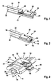
- Fig. 1 shows the end of a wiper blade 10, which has a wiper strip 12 and as a support element two spring rails 22. These are used in two lateral longitudinal grooves 20 of a head strip 18 of the wiper strip 12 and connected at their ends via a bridge 24 firmly together.
- the wiper strip 12 has a wiper lip 14, which via a tilting ridge 16 with the Header 18 is connected.
- a wiper blade end 25 is provided, which comprises a base element 26 and a tip holder 40.
- the base element 26, which has a flat cross-sectional profile, is pushed onto the spring rails 22 from the end of the wiper blade 10 and guided between longitudinal flanges 36 and a cover wall 34.
- top wall 34 In the top wall 34 is a detent opening 28 which is adapted to the contour of the bridge 24 and which engages with the bridge 24 during assembly.
- the bridge 24 may be substantially flush with the outer contour of the top wall 34 in the assembled state, so that it results in a harmonious design.
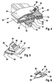
- the base member 26 has a side opening 30 into which the tip holder 40 is inserted. Serve for this purpose at the edges of the opening 30 guide rails 32 which engage in lateral guide grooves 48 on a guide block 46 of the tip holder 40.
- the tip holder 40 is fixed in its end position by a notch 42, which is integrally formed on the guide block 46 and engages with a latching edge 44 in a notch 38 on the inside of the top wall 34.
- the latching notch 38 are arranged on the tip holder 40 and the latching edge 44 on the base element 26.
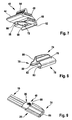
- a slot for a top sheet 60 is essentially formed by two spaced apart at a distance guide grooves 58. These take on the top plate 60 laterally molded guide cheeks 62.
- the tip plate 60 is inserted into the guide grooves 58 so that its tip 66 faces the wiper strip 12.
- the Tip 66 is bounded to the bottom 64 of the tip plate 60 by abutment surfaces 68.
- the top plate 60 is advantageously made of a steel sheet in a sheet metal bending and stamping process, wherein in the bottom 64, a detent hole 70 is punched, which cooperates with a latching pin 72 which is arranged on the top plate 60 facing side of the guide block 46 between the guide grooves 58 is.
- the steel sheet allows a flat, yet stable design of the tip plate 60, wherein the tip 66 may be shaped as a lancet.
- the tip plate 60 When the tip plate 60 is mounted in the tip holder 40, its tip 66 protrudes slightly beyond the guide grooves 58, so that the tip 66, when mounted above the spring rails 22, penetrates into a longitudinal ridge between the longitudinal grooves 20 of the head strip 18.
- the wiper strip 12 is fixed relative to the spring rails 22 via the wiper strip end 25.
- the associated spring rail 22 is covered in the region of the tip holder 40 on its longitudinal side by an end wall 52, which is integrally formed on the tip holder 40. For better guidance of the tip holder 40 are in the region of the end wall 52 guide webs 50 which engage in corresponding grooves of the base member 26.
- the tip holder 40 For unlocking the tip holder 40 has a key 54 with a gripping surface 56. With this button 54, the locking edge 44 can be pressed out of the notch 38, so that the tip holder 40 can be pushed against the mounting direction of the base member 26. At the same time, the tip 66 of the tip plate 60 is removed from the wiper strip 12 so that it can be pulled out of the space between the spring rails 22. If the wiper blade 10 has a spoiler, which is not shown, the wiper strip closure comprises Conveniently, a cap 74 which is guided with guide profiles 78 on the base member 26 and fixed with locking elements in the form of notches 82 in the lower legs 80 of the guide profiles 78 and locking cams 84 on the base member 26.
- the cap 74 has on its upstream side a wind deflector 76, which is adapted to the wind deflector of the spoiler. Further, at the open end face, which is directed opposite to an outwardly directed closed end wall 86 of the cap 74, a connection profile 88 is provided which ensures a harmonious, flow-favorable transition between the end of the spoiler and the cap 74.
- the key 54 is expediently arranged in the area of the highest elevation of the wind deflector 76. It is the inner contour of the cap 74 adjusted so that the outer contour, in particular the wind deflector 76 is not affected by the key 54.
Landscapes
- Engineering & Computer Science (AREA)
- Mechanical Engineering (AREA)
- Insertion Pins And Rivets (AREA)
- Brushes (AREA)
- Cleaning Implements For Floors, Carpets, Furniture, Walls, And The Like (AREA)
- Ink Jet (AREA)
Abstract
Claims (10)
- Balai d'essuie-glace (10) comprenant une raclette d'essuie-glace (12) et deux rails élastiques (22) servant d'élément de support, qui sont insérés dans des rainures longitudinales latérales (20) de la raclette d'essuie-glace (12) et qui sont connectés fixement l'un à l'autre à leurs extrémités par un pont (24), une terminaison de balai d'essuie-glace (25) étant prévue à l'extrémité du balai d'essuie-glace (10), dont l'élément de base (26) est guidé sur les rails élastiques (22), est fixé par rapport aux rails élastiques (22) et présente un support à pointe (40), dont la pointe (66) vient en prise dans la raclette d'essuie-glace (12) dans l'état monté et fixe la raclette d'essuie-glace (12) par rapport aux rails élastiques (22), et l'élément de base (26) présentant dans sa paroi de recouvrement (34) une ouverture d'encliquetage (28) qui s'encliquète lors du montage avec le pont (24), caractérisé en ce que l'élément de base possède une ouverture latérale (30) dans laquelle le support à pointe (40) peut être introduit et s'encliquète dans la position d'extrémité sur l'élément de base (26), la pointe (66) pénétrant latéralement dans la raclette d'essuie-glace (12).
- Balai d'essuie-glace (10) selon la revendication 1, caractérisé en ce que le support à pointe (40) possède un bloc de guidage (46) avec des rainures de guidage latérales (48), qui s'adaptent à des nervures de guidage (50) sur le bord de l'ouverture latérale (30).
- Balai d'essuie-glace (10) selon la revendication 2, caractérisé en ce qu'un cliquet (42) est formé sur le bloc de guidage (46) dans la direction de montage, lequel cliquet s'encliquète dans l'état monté avec une arête d'encliquetage (44) dans une encoche d'encliquetage (38) sur le côté intérieur de la paroi de recouvrement (34).
- Balai d'essuie-glace (10) selon l'une quelconque des revendications 2 ou 3, caractérisé en ce qu'un compartiment d'enfoncement pour une tôle en pointe (60) se trouve sur le côté intérieur du bloc de guidage (46) entre deux rainures de guidage (58), la pointe (66) de la tôle en pointe étant orientée vers la raclette d'essuie-glace (12).
- Balai d'essuie-glace (10) selon la revendication 4, caractérisé en ce que la tôle en pointe (60) présente dans son fond (64) un élément d'encliquetage (70) qui s'encliquète avec un élément d'encliquetage correspondant (84) sur le support à pointe (40).
- Balai d'essuie-glace (10) selon l'une quelconque des revendications 2 à 5, caractérisé en ce qu'une touche (54) pour desserrer le cliquet (42) est disposée sur le bloc de guidage (46).
- Balai d'essuie-glace (10) selon l'une quelconque des revendications précédentes, caractérisé en ce qu'un chapeau de recouvrement (74) recouvre l'élément de base (26) et le support à pointe (40), lequel chapeau de recouvrement est guidé avec des profilés de guidage (78) sur l'élément de base (26) et possède à une extrémité une paroi frontale fermée (86).
- Balai d'essuie-glace (10) selon la revendication 7, caractérisé en ce que le chapeau de recouvrement (74) possède sur son côté d'afflux un profilé déflecteur d'air (76) et sur son côté frontal ouvert un profilé de raccordement (88) pour le raccordement à un déflecteur.
- Balai d'essuie-glace (10) selon la revendication 7, caractérisé en ce que la touche (54) est disposée dans la région du rehaussement maximum du profilé déflecteur d'air (76) et est adaptée au contour interne du chapeau de recouvrement (74).
- Balai d'essuie-glace (10) selon l'une quelconque des revendications 7 à 9, caractérisé en ce que des éléments d'encliquetage (82) sont prévus sur les branches inférieures (80) des profilés de guidage (78), lesquels coopèrent avec des éléments d'encliquetage (84) sur l'élément de base (26).
Priority Applications (1)
| Application Number | Priority Date | Filing Date | Title |
|---|---|---|---|
| PL08786132T PL2190703T3 (pl) | 2007-09-12 | 2008-07-14 | Pióro wycieraczki |
Applications Claiming Priority (2)
| Application Number | Priority Date | Filing Date | Title |
|---|---|---|---|
| DE102007043528A DE102007043528A1 (de) | 2007-09-12 | 2007-09-12 | Wischblatt |
| PCT/EP2008/059176 WO2009033854A1 (fr) | 2007-09-12 | 2008-07-14 | Balai d'essuie-glace |
Publications (2)
| Publication Number | Publication Date |
|---|---|
| EP2190703A1 EP2190703A1 (fr) | 2010-06-02 |
| EP2190703B1 true EP2190703B1 (fr) | 2012-06-20 |
Family
ID=39691299
Family Applications (1)
| Application Number | Title | Priority Date | Filing Date |
|---|---|---|---|
| EP08786132A Not-in-force EP2190703B1 (fr) | 2007-09-12 | 2008-07-14 | Balai d'essuie-glace |
Country Status (11)
| Country | Link |
|---|---|
| US (1) | US8375503B2 (fr) |
| EP (1) | EP2190703B1 (fr) |
| JP (1) | JP5006969B2 (fr) |
| KR (1) | KR101489192B1 (fr) |
| CN (1) | CN101801742B (fr) |
| BR (1) | BRPI0817080B1 (fr) |
| DE (1) | DE102007043528A1 (fr) |
| ES (1) | ES2385769T3 (fr) |
| PL (1) | PL2190703T3 (fr) |
| RU (1) | RU2468941C2 (fr) |
| WO (1) | WO2009033854A1 (fr) |
Families Citing this family (25)
| Publication number | Priority date | Publication date | Assignee | Title |
|---|---|---|---|---|
| DE102010042095A1 (de) * | 2009-10-09 | 2011-04-14 | Robert Bosch Gmbh | Wischblatt |
| US8495787B2 (en) | 2010-08-03 | 2013-07-30 | Rally Manufacturing, Inc. | Windshield wiper |
| JP5666684B2 (ja) * | 2011-02-23 | 2015-02-12 | 株式会社ミツバ | ワイパブレード |
| FR2973313B1 (fr) * | 2011-03-31 | 2013-05-03 | Valeo Systemes Dessuyage | Partie primaire et partie secondaire d'un embout d'extremite pour balai d'essuyage |
| FR2973312B1 (fr) * | 2011-03-31 | 2013-05-03 | Valeo Systemes Dessuyage | Embout d'extremite pour balai d'essuyage |
| US9457768B2 (en) | 2011-04-21 | 2016-10-04 | Pylon Manufacturing Corp. | Vortex damping wiper blade |
| DE102011078168A1 (de) * | 2011-06-28 | 2013-01-03 | Robert Bosch Gmbh | Wischblattvorrichtung |
| MX345011B (es) | 2011-07-28 | 2017-01-11 | Pylon Mfg Corp | Adaptador, conector y conjunto de limpiaparabrisas. |
| US9108595B2 (en) | 2011-07-29 | 2015-08-18 | Pylon Manufacturing Corporation | Windshield wiper connector |
| EP2790972B1 (fr) * | 2011-12-14 | 2017-10-18 | Federal-Mogul S.a. | Dispositif d'essuie-glace |
| CN103171523B (zh) * | 2011-12-26 | 2015-04-22 | 宁波汉德汽车配件有限公司 | 软骨雨刮片 |
| US10723322B2 (en) | 2012-02-24 | 2020-07-28 | Pylon Manufacturing Corp. | Wiper blade with cover |
| US20130219649A1 (en) | 2012-02-24 | 2013-08-29 | Pylon Manufacturing Corp. | Wiper blade |
| RU2577981C1 (ru) | 2012-02-24 | 2016-03-20 | Пилон Мануфэкчуринг Корп. | Щетка стеклоочистителя |
| US10829092B2 (en) | 2012-09-24 | 2020-11-10 | Pylon Manufacturing Corp. | Wiper blade with modular mounting base |
| US10166951B2 (en) | 2013-03-15 | 2019-01-01 | Pylon Manufacturing Corp. | Windshield wiper connector |
| DE102013226036A1 (de) | 2013-11-05 | 2015-05-07 | Robert Bosch Gmbh | Endkappenvorrichtung |
| US9505380B2 (en) | 2014-03-07 | 2016-11-29 | Pylon Manufacturing Corp. | Windshield wiper connector and assembly |
| IL233429A (en) | 2014-06-26 | 2017-11-30 | Dan Tyroler | mop |
| US10363905B2 (en) | 2015-10-26 | 2019-07-30 | Pylon Manufacturing Corp. | Wiper blade |
| CN109311450A (zh) | 2016-05-19 | 2019-02-05 | 电缆塔制造有限公司 | 挡风玻璃雨刮器连接器 |
| US11040705B2 (en) | 2016-05-19 | 2021-06-22 | Pylon Manufacturing Corp. | Windshield wiper connector |
| WO2017201458A1 (fr) | 2016-05-19 | 2017-11-23 | Pylon Manufacturing Corp. | Raccord d'essuie-glace |
| EP3458315B1 (fr) | 2016-05-19 | 2021-09-08 | Pylon Manufacturing Corp. | Balai d'essuie-glace |
| AU2017268008A1 (en) | 2016-05-19 | 2018-11-22 | Pylon Manufacturing Corp. | Windshield wiper connector |
Family Cites Families (16)
| Publication number | Priority date | Publication date | Assignee | Title |
|---|---|---|---|---|
| US3041654A (en) * | 1957-03-25 | 1962-07-03 | John W Anderson | Windshield wiper blade |
| IT1244564B (it) * | 1990-09-24 | 1994-07-28 | Champion Spark Plug Divisione | Spatola tergicristallo monostruttura e relativo procedimento di fabbricazione |
| DE19811702A1 (de) * | 1998-03-18 | 1999-09-23 | Itt Mfg Enterprises Inc | Wischblatt und Austauschsatz für ein Wischblatt |
| DE19856300A1 (de) * | 1998-12-07 | 2000-06-08 | Bosch Gmbh Robert | Wischblatt für Scheiben von Kraftfahrzeugen |
| DE19906288A1 (de) * | 1999-02-15 | 2000-08-17 | Bosch Gmbh Robert | Vorrichtung zum gelenkigen Verbinden eines Wischblatts für Scheiben von Kraftfahrzeugen mit einem Wischerarm |
| DE10139104A1 (de) | 2001-08-09 | 2003-03-06 | Valeo Auto Electric Gmbh | Wischblatt, insbesondere Flachwischblatt |
| DE10245693A1 (de) | 2002-09-30 | 2004-04-08 | Robert Bosch Gmbh | Vorrichtung mit einem federelastischen Tragmittel für eine Wischleiste |
| DE10259478A1 (de) | 2002-12-19 | 2004-07-01 | Robert Bosch Gmbh | Wischvorrichtung für Scheiben von Kraftfahrzeugen |
| DE102004015423A1 (de) * | 2004-03-26 | 2005-10-13 | Robert Bosch Gmbh | Wischblatt |
| DE102004019157A1 (de) * | 2004-04-21 | 2005-11-10 | Robert Bosch Gmbh | Wischblatt |
| DE102004051467A1 (de) | 2004-05-28 | 2005-12-15 | Robert Bosch Gmbh | Wischblatt |
| DE102004051466A1 (de) * | 2004-05-28 | 2005-12-15 | Robert Bosch Gmbh | Wischblatt |
| KR100633643B1 (ko) * | 2004-11-24 | 2006-10-11 | 현대자동차주식회사 | 러버 교체가 가능한 자동차 와이퍼 블레이드의 엔드 클립 |
| EP1698533B1 (fr) * | 2005-03-02 | 2008-09-10 | Federal-Mogul S.A. | Dispositif d'essuie-glace |
| FR2893290B1 (fr) | 2005-09-13 | 2009-05-01 | Valeo Systemes Dessuyage | Dispositif de verrouillage entre une lame d'essuyage et un porte-balai d'essuie-glace |
| US8745813B2 (en) * | 2006-08-18 | 2014-06-10 | Robert Bosch Gmbh | Wiper blade with a supporting element |
-
2007
- 2007-09-12 DE DE102007043528A patent/DE102007043528A1/de not_active Withdrawn
-
2008
- 2008-07-14 EP EP08786132A patent/EP2190703B1/fr not_active Not-in-force
- 2008-07-14 WO PCT/EP2008/059176 patent/WO2009033854A1/fr active Application Filing
- 2008-07-14 ES ES08786132T patent/ES2385769T3/es active Active
- 2008-07-14 US US12/669,822 patent/US8375503B2/en not_active Expired - Fee Related
- 2008-07-14 KR KR1020107004897A patent/KR101489192B1/ko active IP Right Grant
- 2008-07-14 CN CN2008801065190A patent/CN101801742B/zh not_active Expired - Fee Related
- 2008-07-14 PL PL08786132T patent/PL2190703T3/pl unknown
- 2008-07-14 RU RU2010113720/11A patent/RU2468941C2/ru not_active IP Right Cessation
- 2008-07-14 BR BRPI0817080-0A patent/BRPI0817080B1/pt not_active IP Right Cessation
- 2008-07-14 JP JP2010524425A patent/JP5006969B2/ja not_active Expired - Fee Related
Also Published As
| Publication number | Publication date |
|---|---|
| WO2009033854A1 (fr) | 2009-03-19 |
| PL2190703T3 (pl) | 2012-11-30 |
| KR20100053611A (ko) | 2010-05-20 |
| RU2468941C2 (ru) | 2012-12-10 |
| JP5006969B2 (ja) | 2012-08-22 |
| ES2385769T3 (es) | 2012-07-31 |
| DE102007043528A1 (de) | 2009-03-19 |
| US8375503B2 (en) | 2013-02-19 |
| BRPI0817080B1 (pt) | 2019-08-20 |
| CN101801742B (zh) | 2012-07-11 |
| US20100180395A1 (en) | 2010-07-22 |
| KR101489192B1 (ko) | 2015-02-03 |
| EP2190703A1 (fr) | 2010-06-02 |
| BRPI0817080A2 (pt) | 2015-03-24 |
| CN101801742A (zh) | 2010-08-11 |
| JP2010538893A (ja) | 2010-12-16 |
| RU2010113720A (ru) | 2011-10-20 |
Similar Documents
| Publication | Publication Date | Title |
|---|---|---|
| EP2190703B1 (fr) | Balai d'essuie-glace | |
| EP1966013B1 (fr) | Element de raccordement | |
| EP2424755B1 (fr) | Dispositif de raccordement, destine a relier de maniere articulee un element de liaison solidaire d'un bras d'essuie-glace | |
| EP2321160B1 (fr) | Dispositif de liaison articulée entre un balai d essuie-glace et un bras d essuie-glace | |
| EP2326538B1 (fr) | Dispositif de raccordement permettant de realiser une liaison articulee entre un balai d'essuie-glace et un bras d'essuie-glace | |
| EP1877290B1 (fr) | Bras d'essuie-glace avec un balai d'essuie-glace | |
| EP2121394B1 (fr) | Élément de liaison pour la liaison articulée d'un balai d'essuie-glace à un bras d'essuie-glace | |
| EP2477853B1 (fr) | Balai d'essuie-glace à structure en forme de barre plate | |
| DE102010041152A1 (de) | Adapter zum Verbinden eines Verbindungselements am Ende eines Wischarms mit einem Wischblatt insbesondere in Flachbalkenbauweise | |
| EP2485926A1 (fr) | Balai d'essuie-glace | |
| EP2162321A1 (fr) | Balai d'essuie-glace plat | |
| DE102006061680A1 (de) | Wischblatt | |
| EP2450244A1 (fr) | Raclette d'essuie-glace | |
| WO2010017861A1 (fr) | Essuie-glace sur un véhicule | |
| WO2012159802A1 (fr) | Balai d'essuie-glace | |
| DE102011003838A1 (de) | Vorrichtung zum gelenkigen Verbinden eines Wischblatts in Flachbalkenbauweise mit einem Wischarm | |
| EP2177407A1 (fr) | Raclette d'essuie-glace | |
| DE102005020601A1 (de) | Vorrichtung zum gelenkigen Verbinden eines Wischblatts mit einem Wischarm | |
| EP2097298B1 (fr) | Balai d'essuie-glace | |
| DE102008040033A1 (de) | Baureihe eines Wischblatts | |
| EP2214936B1 (fr) | Balai d'essuie-glace |
Legal Events
| Date | Code | Title | Description |
|---|---|---|---|
| PUAI | Public reference made under article 153(3) epc to a published international application that has entered the european phase |
Free format text: ORIGINAL CODE: 0009012 |
|
| 17P | Request for examination filed |
Effective date: 20100412 |
|
| AK | Designated contracting states |
Kind code of ref document: A1 Designated state(s): AT BE BG CH CY CZ DE DK EE ES FI FR GB GR HR HU IE IS IT LI LT LU LV MC MT NL NO PL PT RO SE SI SK TR |
|
| AX | Request for extension of the european patent |
Extension state: AL BA MK RS |
|
| DAX | Request for extension of the european patent (deleted) | ||
| 17Q | First examination report despatched |
Effective date: 20110926 |
|
| GRAP | Despatch of communication of intention to grant a patent |
Free format text: ORIGINAL CODE: EPIDOSNIGR1 |
|
| GRAS | Grant fee paid |
Free format text: ORIGINAL CODE: EPIDOSNIGR3 |
|
| GRAA | (expected) grant |
Free format text: ORIGINAL CODE: 0009210 |
|
| AK | Designated contracting states |
Kind code of ref document: B1 Designated state(s): AT BE BG CH CY CZ DE DK EE ES FI FR GB GR HR HU IE IS IT LI LT LU LV MC MT NL NO PL PT RO SE SI SK TR |
|
| REG | Reference to a national code |
Ref country code: GB Ref legal event code: FG4D Free format text: NOT ENGLISH |
|
| REG | Reference to a national code |
Ref country code: CH Ref legal event code: EP |
|
| REG | Reference to a national code |
Ref country code: AT Ref legal event code: REF Ref document number: 562874 Country of ref document: AT Kind code of ref document: T Effective date: 20120715 |
|
| REG | Reference to a national code |
Ref country code: IE Ref legal event code: FG4D Free format text: LANGUAGE OF EP DOCUMENT: GERMAN |
|
| REG | Reference to a national code |
Ref country code: ES Ref legal event code: FG2A Ref document number: 2385769 Country of ref document: ES Kind code of ref document: T3 Effective date: 20120731 |
|
| REG | Reference to a national code |
Ref country code: DE Ref legal event code: R096 Ref document number: 502008007507 Country of ref document: DE Effective date: 20120816 |
|
| REG | Reference to a national code |
Ref country code: RO Ref legal event code: EPE |
|
| REG | Reference to a national code |
Ref country code: SE Ref legal event code: TRGR |
|
| REG | Reference to a national code |
Ref country code: NL Ref legal event code: T3 |
|
| PG25 | Lapsed in a contracting state [announced via postgrant information from national office to epo] |
Ref country code: NO Free format text: LAPSE BECAUSE OF FAILURE TO SUBMIT A TRANSLATION OF THE DESCRIPTION OR TO PAY THE FEE WITHIN THE PRESCRIBED TIME-LIMIT Effective date: 20120920 Ref country code: LT Free format text: LAPSE BECAUSE OF FAILURE TO SUBMIT A TRANSLATION OF THE DESCRIPTION OR TO PAY THE FEE WITHIN THE PRESCRIBED TIME-LIMIT Effective date: 20120620 Ref country code: FI Free format text: LAPSE BECAUSE OF FAILURE TO SUBMIT A TRANSLATION OF THE DESCRIPTION OR TO PAY THE FEE WITHIN THE PRESCRIBED TIME-LIMIT Effective date: 20120620 |
|
| REG | Reference to a national code |
Ref country code: LT Ref legal event code: MG4D Effective date: 20120627 |
|
| PG25 | Lapsed in a contracting state [announced via postgrant information from national office to epo] |
Ref country code: LV Free format text: LAPSE BECAUSE OF FAILURE TO SUBMIT A TRANSLATION OF THE DESCRIPTION OR TO PAY THE FEE WITHIN THE PRESCRIBED TIME-LIMIT Effective date: 20120620 Ref country code: GR Free format text: LAPSE BECAUSE OF FAILURE TO SUBMIT A TRANSLATION OF THE DESCRIPTION OR TO PAY THE FEE WITHIN THE PRESCRIBED TIME-LIMIT Effective date: 20120921 Ref country code: SI Free format text: LAPSE BECAUSE OF FAILURE TO SUBMIT A TRANSLATION OF THE DESCRIPTION OR TO PAY THE FEE WITHIN THE PRESCRIBED TIME-LIMIT Effective date: 20120620 Ref country code: HR Free format text: LAPSE BECAUSE OF FAILURE TO SUBMIT A TRANSLATION OF THE DESCRIPTION OR TO PAY THE FEE WITHIN THE PRESCRIBED TIME-LIMIT Effective date: 20120620 |
|
| REG | Reference to a national code |
Ref country code: PL Ref legal event code: T3 |
|
| PG25 | Lapsed in a contracting state [announced via postgrant information from national office to epo] |
Ref country code: CY Free format text: LAPSE BECAUSE OF FAILURE TO SUBMIT A TRANSLATION OF THE DESCRIPTION OR TO PAY THE FEE WITHIN THE PRESCRIBED TIME-LIMIT Effective date: 20120620 Ref country code: EE Free format text: LAPSE BECAUSE OF FAILURE TO SUBMIT A TRANSLATION OF THE DESCRIPTION OR TO PAY THE FEE WITHIN THE PRESCRIBED TIME-LIMIT Effective date: 20120620 Ref country code: IS Free format text: LAPSE BECAUSE OF FAILURE TO SUBMIT A TRANSLATION OF THE DESCRIPTION OR TO PAY THE FEE WITHIN THE PRESCRIBED TIME-LIMIT Effective date: 20121020 Ref country code: SK Free format text: LAPSE BECAUSE OF FAILURE TO SUBMIT A TRANSLATION OF THE DESCRIPTION OR TO PAY THE FEE WITHIN THE PRESCRIBED TIME-LIMIT Effective date: 20120620 |
|
| PG25 | Lapsed in a contracting state [announced via postgrant information from national office to epo] |
Ref country code: PT Free format text: LAPSE BECAUSE OF FAILURE TO SUBMIT A TRANSLATION OF THE DESCRIPTION OR TO PAY THE FEE WITHIN THE PRESCRIBED TIME-LIMIT Effective date: 20121022 Ref country code: MC Free format text: LAPSE BECAUSE OF NON-PAYMENT OF DUE FEES Effective date: 20120731 |
|
| REG | Reference to a national code |
Ref country code: CH Ref legal event code: PL |
|
| PLBE | No opposition filed within time limit |
Free format text: ORIGINAL CODE: 0009261 |
|
| STAA | Information on the status of an ep patent application or granted ep patent |
Free format text: STATUS: NO OPPOSITION FILED WITHIN TIME LIMIT |
|
| PG25 | Lapsed in a contracting state [announced via postgrant information from national office to epo] |
Ref country code: LI Free format text: LAPSE BECAUSE OF NON-PAYMENT OF DUE FEES Effective date: 20120731 Ref country code: DK Free format text: LAPSE BECAUSE OF FAILURE TO SUBMIT A TRANSLATION OF THE DESCRIPTION OR TO PAY THE FEE WITHIN THE PRESCRIBED TIME-LIMIT Effective date: 20120620 Ref country code: CH Free format text: LAPSE BECAUSE OF NON-PAYMENT OF DUE FEES Effective date: 20120731 |
|
| REG | Reference to a national code |
Ref country code: IE Ref legal event code: MM4A |
|
| 26N | No opposition filed |
Effective date: 20130321 |
|
| REG | Reference to a national code |
Ref country code: HU Ref legal event code: AG4A Ref document number: E015369 Country of ref document: HU |
|
| REG | Reference to a national code |
Ref country code: DE Ref legal event code: R097 Ref document number: 502008007507 Country of ref document: DE Effective date: 20130321 |
|
| PG25 | Lapsed in a contracting state [announced via postgrant information from national office to epo] |
Ref country code: BG Free format text: LAPSE BECAUSE OF FAILURE TO SUBMIT A TRANSLATION OF THE DESCRIPTION OR TO PAY THE FEE WITHIN THE PRESCRIBED TIME-LIMIT Effective date: 20120920 Ref country code: MT Free format text: LAPSE BECAUSE OF FAILURE TO SUBMIT A TRANSLATION OF THE DESCRIPTION OR TO PAY THE FEE WITHIN THE PRESCRIBED TIME-LIMIT Effective date: 20120620 Ref country code: IE Free format text: LAPSE BECAUSE OF NON-PAYMENT OF DUE FEES Effective date: 20120714 |
|
| PG25 | Lapsed in a contracting state [announced via postgrant information from national office to epo] |
Ref country code: TR Free format text: LAPSE BECAUSE OF FAILURE TO SUBMIT A TRANSLATION OF THE DESCRIPTION OR TO PAY THE FEE WITHIN THE PRESCRIBED TIME-LIMIT Effective date: 20120620 |
|
| PG25 | Lapsed in a contracting state [announced via postgrant information from national office to epo] |
Ref country code: LU Free format text: LAPSE BECAUSE OF NON-PAYMENT OF DUE FEES Effective date: 20120714 |
|
| REG | Reference to a national code |
Ref country code: AT Ref legal event code: MM01 Ref document number: 562874 Country of ref document: AT Kind code of ref document: T Effective date: 20130714 |
|
| PG25 | Lapsed in a contracting state [announced via postgrant information from national office to epo] |
Ref country code: AT Free format text: LAPSE BECAUSE OF NON-PAYMENT OF DUE FEES Effective date: 20130714 |
|
| REG | Reference to a national code |
Ref country code: FR Ref legal event code: PLFP Year of fee payment: 9 |
|
| REG | Reference to a national code |
Ref country code: FR Ref legal event code: PLFP Year of fee payment: 10 |
|
| REG | Reference to a national code |
Ref country code: FR Ref legal event code: PLFP Year of fee payment: 11 |
|
| PGFP | Annual fee paid to national office [announced via postgrant information from national office to epo] |
Ref country code: NL Payment date: 20190722 Year of fee payment: 12 |
|
| PGFP | Annual fee paid to national office [announced via postgrant information from national office to epo] |
Ref country code: DE Payment date: 20190924 Year of fee payment: 12 Ref country code: FR Payment date: 20190724 Year of fee payment: 12 Ref country code: CZ Payment date: 20190704 Year of fee payment: 12 Ref country code: RO Payment date: 20190710 Year of fee payment: 12 Ref country code: IT Payment date: 20190723 Year of fee payment: 12 Ref country code: ES Payment date: 20190822 Year of fee payment: 12 Ref country code: SE Payment date: 20190725 Year of fee payment: 12 |
|
| PGFP | Annual fee paid to national office [announced via postgrant information from national office to epo] |
Ref country code: HU Payment date: 20190702 Year of fee payment: 12 Ref country code: BE Payment date: 20190722 Year of fee payment: 12 Ref country code: PL Payment date: 20190705 Year of fee payment: 12 |
|
| PGFP | Annual fee paid to national office [announced via postgrant information from national office to epo] |
Ref country code: GB Payment date: 20190725 Year of fee payment: 12 |
|
| REG | Reference to a national code |
Ref country code: DE Ref legal event code: R119 Ref document number: 502008007507 Country of ref document: DE |
|
| REG | Reference to a national code |
Ref country code: SE Ref legal event code: EUG |
|
| REG | Reference to a national code |
Ref country code: NL Ref legal event code: MM Effective date: 20200801 |
|
| GBPC | Gb: european patent ceased through non-payment of renewal fee |
Effective date: 20200714 |
|
| REG | Reference to a national code |
Ref country code: BE Ref legal event code: MM Effective date: 20200731 |
|
| PG25 | Lapsed in a contracting state [announced via postgrant information from national office to epo] |
Ref country code: GB Free format text: LAPSE BECAUSE OF NON-PAYMENT OF DUE FEES Effective date: 20200714 Ref country code: FR Free format text: LAPSE BECAUSE OF NON-PAYMENT OF DUE FEES Effective date: 20200731 Ref country code: RO Free format text: LAPSE BECAUSE OF NON-PAYMENT OF DUE FEES Effective date: 20200714 Ref country code: NL Free format text: LAPSE BECAUSE OF NON-PAYMENT OF DUE FEES Effective date: 20200801 Ref country code: CZ Free format text: LAPSE BECAUSE OF NON-PAYMENT OF DUE FEES Effective date: 20200714 Ref country code: HU Free format text: LAPSE BECAUSE OF NON-PAYMENT OF DUE FEES Effective date: 20200715 |
|
| PG25 | Lapsed in a contracting state [announced via postgrant information from national office to epo] |
Ref country code: BE Free format text: LAPSE BECAUSE OF NON-PAYMENT OF DUE FEES Effective date: 20200731 Ref country code: DE Free format text: LAPSE BECAUSE OF NON-PAYMENT OF DUE FEES Effective date: 20210202 Ref country code: SE Free format text: LAPSE BECAUSE OF NON-PAYMENT OF DUE FEES Effective date: 20200715 |
|
| PG25 | Lapsed in a contracting state [announced via postgrant information from national office to epo] |
Ref country code: IT Free format text: LAPSE BECAUSE OF NON-PAYMENT OF DUE FEES Effective date: 20200714 |
|
| REG | Reference to a national code |
Ref country code: ES Ref legal event code: FD2A Effective date: 20211230 |
|
| PG25 | Lapsed in a contracting state [announced via postgrant information from national office to epo] |
Ref country code: ES Free format text: LAPSE BECAUSE OF NON-PAYMENT OF DUE FEES Effective date: 20200715 |
|
| PG25 | Lapsed in a contracting state [announced via postgrant information from national office to epo] |
Ref country code: PL Free format text: LAPSE BECAUSE OF NON-PAYMENT OF DUE FEES Effective date: 20200714 |