EP2190703B1 - Wischblatt - Google Patents
Wischblatt Download PDFInfo
- Publication number
- EP2190703B1 EP2190703B1 EP08786132A EP08786132A EP2190703B1 EP 2190703 B1 EP2190703 B1 EP 2190703B1 EP 08786132 A EP08786132 A EP 08786132A EP 08786132 A EP08786132 A EP 08786132A EP 2190703 B1 EP2190703 B1 EP 2190703B1
- Authority
- EP
- European Patent Office
- Prior art keywords
- wiper blade
- tip
- pointed
- base element
- wiper
- Prior art date
- Legal status (The legal status is an assumption and is not a legal conclusion. Google has not performed a legal analysis and makes no representation as to the accuracy of the status listed.)
- Not-in-force
Links
Images

Classifications
-
- B—PERFORMING OPERATIONS; TRANSPORTING
- B60—VEHICLES IN GENERAL
- B60S—SERVICING, CLEANING, REPAIRING, SUPPORTING, LIFTING, OR MANOEUVRING OF VEHICLES, NOT OTHERWISE PROVIDED FOR
- B60S1/00—Cleaning of vehicles
- B60S1/02—Cleaning windscreens, windows or optical devices
- B60S1/04—Wipers or the like, e.g. scrapers
- B60S1/32—Wipers or the like, e.g. scrapers characterised by constructional features of wiper blade arms or blades
- B60S1/38—Wiper blades
- B60S1/3848—Flat-type wiper blade, i.e. without harness
- B60S1/3886—End caps
- B60S1/3887—Mounting of end caps
- B60S1/3891—Mounting of end caps with locking device
-
- B—PERFORMING OPERATIONS; TRANSPORTING
- B60—VEHICLES IN GENERAL
- B60S—SERVICING, CLEANING, REPAIRING, SUPPORTING, LIFTING, OR MANOEUVRING OF VEHICLES, NOT OTHERWISE PROVIDED FOR
- B60S1/00—Cleaning of vehicles
- B60S1/02—Cleaning windscreens, windows or optical devices
- B60S1/04—Wipers or the like, e.g. scrapers
- B60S1/32—Wipers or the like, e.g. scrapers characterised by constructional features of wiper blade arms or blades
- B60S1/38—Wiper blades
- B60S1/3848—Flat-type wiper blade, i.e. without harness
- B60S1/3874—Flat-type wiper blade, i.e. without harness with a reinforcing vertebra
- B60S1/3875—Flat-type wiper blade, i.e. without harness with a reinforcing vertebra rectangular section
- B60S1/3879—Flat-type wiper blade, i.e. without harness with a reinforcing vertebra rectangular section placed in side grooves in the squeegee
-
- B—PERFORMING OPERATIONS; TRANSPORTING
- B60—VEHICLES IN GENERAL
- B60S—SERVICING, CLEANING, REPAIRING, SUPPORTING, LIFTING, OR MANOEUVRING OF VEHICLES, NOT OTHERWISE PROVIDED FOR
- B60S1/00—Cleaning of vehicles
- B60S1/02—Cleaning windscreens, windows or optical devices
- B60S1/04—Wipers or the like, e.g. scrapers
- B60S1/32—Wipers or the like, e.g. scrapers characterised by constructional features of wiper blade arms or blades
- B60S1/38—Wiper blades
- B60S1/3848—Flat-type wiper blade, i.e. without harness
- B60S1/3886—End caps
- B60S1/3894—End caps having a particular shape
-
- B—PERFORMING OPERATIONS; TRANSPORTING
- B60—VEHICLES IN GENERAL
- B60S—SERVICING, CLEANING, REPAIRING, SUPPORTING, LIFTING, OR MANOEUVRING OF VEHICLES, NOT OTHERWISE PROVIDED FOR
- B60S1/00—Cleaning of vehicles
- B60S1/02—Cleaning windscreens, windows or optical devices
- B60S1/04—Wipers or the like, e.g. scrapers
- B60S1/32—Wipers or the like, e.g. scrapers characterised by constructional features of wiper blade arms or blades
- B60S1/38—Wiper blades
- B60S2001/3812—Means of supporting or holding the squeegee or blade rubber
- B60S2001/3822—Means of supporting or holding the squeegee or blade rubber characterised by additional means to prevent longitudinal sliding of squeegee in support, e.g. clips
Definitions
- the invention is based on a wiper blade according to the preamble of claim 1.
- a generic wiper blade known. At the end of the wiper blade a multi-part end cap is provided, the base member is guided by means of guide profiles on the spring rails. With the base element, a lid is hingedly connected, which assumes a closed position in the assembled state. With the lid open, the component is removable from the end of the wiper strip. A worn wiper strip can then be replaced with a new one. After replacement, the base part is added with the lid open on the end of the wiper strip until locking hooks engage with their latching lugs on the side facing away from the end of the wiper blade side of the bridge. As a result, the base part is fixed in the longitudinal direction at the end of the spring rails.
- the lid whose pivot axis extends transversely to the longitudinal direction of the wiper blade, closed, expresses an eccentric mechanism, which is integrally formed on the lid, on a spring tongue.
- This is pivotally mounted on the base member and has on the wiper strip side facing a locking mandrel, whose tip penetrates when closing the lid in the header.
- the wiper strip is fixed over the end cap relative to the spring rails.
- the base part and the lid are preferably made of plastic. They are manufactured as individual components in an injection molding process.
- the mandrel tip is formed directly on the side facing the wiper strip side of the lid and penetrates when closing the lid from above into the head strip of the wiper strip. In the closed position, the lid is locked relative to the base element.
- a generic wiper blade is from the document WO-A-2005/115 813 known.
- the base element has in its top wall a latching opening which locks with the bridge during assembly.
- the bridge can be substantially flush with the outer contour of the top wall, so that the overall result is a flat concept for the wiper blade.
- the base member also has a side opening into which the tip holder can be inserted and locked in the end position on the base member, the tip penetrating laterally into the wiper strip. Due to the lateral arrangement of the tip holder and the tip, the flat overall height of the wiper blade closure is maintained.
- the tip holder has a guide block with lateral guide grooves, which fit to guide webs on the edge of the lateral opening.
- the lateral opening as the guide block are inevitably arranged offset in the longitudinal direction of the wiper blade to the bridge, so that the construction height of the base member is not affected by these structural elements becomes.
- the end position of the tip holder is advantageously effected by a catch which is integrally formed on the guide block in the mounting direction and engages in the assembled state with a latching edge in a notch on the inside of the top wall.
- the arrangement of the locking elements, namely the locking edge and notch, can be reversed.
- the tip of the wiper strip is facing.
- the top plate is locked in an advantageous manner by locking elements on the tip holder. These may consist in a detent hole in the bottom of the tip plate and a locking pin on the tip holder. In principle, however, it is also possible that a latching pin is formed on the top plate, which engages with a recess of the guide block of the tip holder.
- the tip of the tip plate protrudes slightly from the guide grooves toward the wiper strip, but is shielded at a small distance by the catch for fixing the guide block to the base element, thereby greatly reducing the risk of injury prior to assembly of the tip holder. Since the tip is arranged on a steel top plate, it can be stable and yet very flat, so that it easily penetrates into the wiper strip during assembly, without kinking.
- a key is arranged on the guide block. This can project a little way out of the lateral opening, in particular if the base element and the tip holder are covered by a covering cap.
- the cap is with Guide profiles guided on the base element and has at the end a closed end wall. This gives the wiper blade end a compact outer contour with aerodynamic properties and good design qualities.
- the cap can be largely adapted to different circumstances depending on the individual case. Appropriately, it has on its upstream side a Windleitprofil and at its open end a connection profile for connection to a spoiler.
- the button for releasing the tip holder can be arranged in the region of the highest elevation of the Windleitprofils and adapted to the inner contour of the cap, so that the outer contour of the cap is not disturbed thereby.
- locking elements in the form of recesses and projections are provided on the lower legs of the guide profiles of the cap, which engage with each other during assembly.
- the wiper strip is worn, it is usually sufficient that the wiper strip is renewed alone. However, it may also turn out that over time the wiper blade seal has become unsightly or defective. In this case, it is expedient to provide the wiper strip as a separate spare part.
- Fig. 1 shows the end of a wiper blade 10, which has a wiper strip 12 and as a support element two spring rails 22. These are used in two lateral longitudinal grooves 20 of a head strip 18 of the wiper strip 12 and connected at their ends via a bridge 24 firmly together.
- the wiper strip 12 has a wiper lip 14, which via a tilting ridge 16 with the Header 18 is connected.
- a wiper blade end 25 is provided, which comprises a base element 26 and a tip holder 40.
- the base element 26, which has a flat cross-sectional profile, is pushed onto the spring rails 22 from the end of the wiper blade 10 and guided between longitudinal flanges 36 and a cover wall 34.
- top wall 34 In the top wall 34 is a detent opening 28 which is adapted to the contour of the bridge 24 and which engages with the bridge 24 during assembly.
- the bridge 24 may be substantially flush with the outer contour of the top wall 34 in the assembled state, so that it results in a harmonious design.
- the base member 26 has a side opening 30 into which the tip holder 40 is inserted. Serve for this purpose at the edges of the opening 30 guide rails 32 which engage in lateral guide grooves 48 on a guide block 46 of the tip holder 40.
- the tip holder 40 is fixed in its end position by a notch 42, which is integrally formed on the guide block 46 and engages with a latching edge 44 in a notch 38 on the inside of the top wall 34.
- the latching notch 38 are arranged on the tip holder 40 and the latching edge 44 on the base element 26.
- a slot for a top sheet 60 is essentially formed by two spaced apart at a distance guide grooves 58. These take on the top plate 60 laterally molded guide cheeks 62.
- the tip plate 60 is inserted into the guide grooves 58 so that its tip 66 faces the wiper strip 12.
- the Tip 66 is bounded to the bottom 64 of the tip plate 60 by abutment surfaces 68.
- the top plate 60 is advantageously made of a steel sheet in a sheet metal bending and stamping process, wherein in the bottom 64, a detent hole 70 is punched, which cooperates with a latching pin 72 which is arranged on the top plate 60 facing side of the guide block 46 between the guide grooves 58 is.
- the steel sheet allows a flat, yet stable design of the tip plate 60, wherein the tip 66 may be shaped as a lancet.
- the tip plate 60 When the tip plate 60 is mounted in the tip holder 40, its tip 66 protrudes slightly beyond the guide grooves 58, so that the tip 66, when mounted above the spring rails 22, penetrates into a longitudinal ridge between the longitudinal grooves 20 of the head strip 18.
- the wiper strip 12 is fixed relative to the spring rails 22 via the wiper strip end 25.
- the associated spring rail 22 is covered in the region of the tip holder 40 on its longitudinal side by an end wall 52, which is integrally formed on the tip holder 40. For better guidance of the tip holder 40 are in the region of the end wall 52 guide webs 50 which engage in corresponding grooves of the base member 26.
- the tip holder 40 For unlocking the tip holder 40 has a key 54 with a gripping surface 56. With this button 54, the locking edge 44 can be pressed out of the notch 38, so that the tip holder 40 can be pushed against the mounting direction of the base member 26. At the same time, the tip 66 of the tip plate 60 is removed from the wiper strip 12 so that it can be pulled out of the space between the spring rails 22. If the wiper blade 10 has a spoiler, which is not shown, the wiper strip closure comprises Conveniently, a cap 74 which is guided with guide profiles 78 on the base member 26 and fixed with locking elements in the form of notches 82 in the lower legs 80 of the guide profiles 78 and locking cams 84 on the base member 26.
- the cap 74 has on its upstream side a wind deflector 76, which is adapted to the wind deflector of the spoiler. Further, at the open end face, which is directed opposite to an outwardly directed closed end wall 86 of the cap 74, a connection profile 88 is provided which ensures a harmonious, flow-favorable transition between the end of the spoiler and the cap 74.
- the key 54 is expediently arranged in the area of the highest elevation of the wind deflector 76. It is the inner contour of the cap 74 adjusted so that the outer contour, in particular the wind deflector 76 is not affected by the key 54.
Landscapes
- Engineering & Computer Science (AREA)
- Mechanical Engineering (AREA)
- Insertion Pins And Rivets (AREA)
- Brushes (AREA)
- Ink Jet (AREA)
- Cleaning Implements For Floors, Carpets, Furniture, Walls, And The Like (AREA)
Abstract
Description
- Die Erfindung geht von einem Wischblatt nach dem Oberbegriff des Anspruchs 1 aus.
- Aus der
DE 10 2004 051 467 A1 ist ein gattungsgemäßes Wischblatt bekannt. Am Ende des Wischblatts ist eine mehrteilige Endkappe vorgesehen, deren Basiselement mittels Führungsprofilen auf den Federschienen geführt ist. Mit dem Basiselement ist ein Deckel gelenkig verbunden, der in montiertem Zustand eine Verschlussposition einnimmt. Mit geöffnetem Deckel ist das Bauteil vom Ende der Wischleiste abnehmbar. Eine verschlissene Wischleiste kann daraufhin gegen eine neue ausgetauscht werden. Nach dem Austausch wird das Basisteil mit geöffnetem Deckel auf das Ende der Wischleiste gefügt, bis Rasthaken mit ihren Rastnasen an der vom Ende des Wischblatts abgewandten Seite der Brücke verrasten. Dadurch ist das Basisteil in Längsrichtung am Ende der Federschienen fixiert. Wird der Deckel, dessen Schwenkachse quer zur Längsrichtung des Wischblatts verläuft, geschlossen, drückt ein Exzentermechanismus, der am Deckel angeformt ist, auf eine Federzunge. Diese ist am Basiselement schwenkbar angeordnet und besitzt an der der Wischleiste zugewandten Seite einen Verriegelungsdorn, dessen Spitze beim Verschließen des Deckels in die Kopfleiste eindringt. Somit ist die Wischleiste über die Endkappe relativ zu den Federschienen fixiert. - Das Basisteil und der Deckel bestehen vorzugsweise aus Kunststoff. Sie werden als Einzelbauteile in einem Spritzgussverfahren hergestellt. Bei einer Ausgestaltung ist die Dornspitze unmittelbar an der der Wischleiste zugewandten Seite des Deckels angeformt und dringt beim Schließen des Deckels von oben in die Kopfleiste der Wischleiste ein. In der geschlossenen Position wird der Deckel gegenüber dem Basiselement verrastet.
- Ein gattungsgemäßes Wischblett ist aus dem Dokument
WO-A-2005/115 813 bekannt. - Nach der Erfindung besitzt das Basiselement in seiner Deckwand eine Rastöffnung, die mit der Brücke bei der Montage verrastet. Dabei kann die Brücke im Wesentlichen bündig mit der Außenkontur der Deckwand abschließen, sodass sich insgesamt ein flaches Konzept für den Wischblattabschluss ergibt. Das Basiselement besitzt außerdem eine seitliche Öffnung, in die der Spitzenhalter eingeführt werden kann und in der Endposition am Basiselement verrastet, wobei die Spitze seitlich in die Wischleiste eindringt. Durch die seitliche Anordnung des Spitzenhalters und der Spitze bleibt die flache Bauhöhe des Wischblattabschlusses erhalten. Gemäß einer Ausgestaltung der Erfindung besitzt der Spitzenhalter einen Führungsblock mit seitlichen Führungsnuten, die zu Führungsstegen am Rande der seitlichen Öffnung passen. Die seitliche Öffnung wie der Führungsblock sind zwangsläufig in Längsrichtung des Wischblatts versetzt zur Brücke angeordnet, sodass durch diese Konstruktionselemente die Bauhöhe des Basiselements nicht beeinflusst wird. Die Endposition des Spitzenhalters wird zweckmäßigerweise durch eine Raste bewirkt, die an dem Führungsblock in Montagerichtung angeformt ist und in montiertem Zustand mit einer Rastkante in eine Rastkerbe an der Innenseite der Deckwand einrastet. Die Anordnung der Rastelemente, nämlich der Rastkante und Rastkerbe, kann vertauscht werden.
- Gemäß einer weiteren Ausgestaltung der Erfindung befindet sich auf der Innenseite des Führungsblocks zwischen zwei Führungsnuten ein Einschubfach für ein Spitzenblech, dessen Spitze der Wischleiste zugewandt ist. Dabei ist das Spitzenblech in vorteilhafter Weise durch Rastelemente am Spitzenhalter verrastet. Diese können in einem Rastloch im Boden des Spitzenblechs und einem Rastzapfen am Spitzenhalter bestehen. Grundsätzlich ist es jedoch auch möglich, dass an dem Spitzenblech ein Rastzapfen angeformt ist, der mit einer Vertiefung des Führungsblocks des Spitzenhalters verrastet. Die Spitze des Spitzenblechs ragt ein Stück weit aus den Führungsnuten zur Wischleiste hin vor, wird aber mit einem geringen Abstand durch die Raste zum Fixieren des Führungsblocks am Basiselement abgeschirmt, wodurch die Verletzungsgefahr vor der Montage des Spitzenhalters stark verringert wird. Da die Spitze an einem Spitzenblech aus Stahl angeordnet ist, kann sie stabil und doch sehr flach ausgebildet sein, sodass sie bei der Montage leicht in die Wischleiste eindringt, ohne abzuknicken.
- Zum Lösen der Raste, die den Spitzenhalter am Basiselement fixiert, ist am Führungsblock eine Taste angeordnet. Diese kann ein Stück weit aus der seitlichen Öffnung vorstehen, insbesondere wenn das Basiselement und der Spitzenhalter von einer Abdeckkappe überdeckt werden. Die Abdeckkappe ist mit Führungsprofilen auf dem Basiselement geführt und besitzt am Ende eine geschlossene Stirnwand. Dadurch erhält der Wischblattabschluss eine kompakte Außenkontur mit strömungsgünstigen Eigenschaften und guten Designqualitäten. Die Abdeckkappe kann weitgehend je nach Einzelfall an unterschiedliche Gegebenheiten angepasst werden. Zweckmäßigerweise besitzt sie an ihrer Anströmseite ein Windleitprofil und an ihrer offenen Stirnseite ein Anschlussprofil zum Anschluss an einen Spoiler. In diesem Fall kann die Taste zum Lösen des Spitzenhalters im Bereich der höchsten Erhebung des Windleitprofils angeordnet und der Innenkontur der Abdeckkappe angepasst werden, sodass die Außenkontur der Abdeckkappe dadurch nicht gestört wird.
- Zum Fixieren der Abdeckkappe auf dem Basiselement sind an den unteren Schenkeln der Führungsprofile der Abdeckkappe Rastelemente in Form von Aussparungen und Vorsprüngen vorgesehen, die bei der Montage miteinander verrasten.
- Wenn die Wischleiste verschlissen ist, reicht es in der Regel aus, dass die Wischleiste allein erneuert wird. Es kann sich jedoch auch ergeben, dass der Wischblattabschluss im Laufe der Zeit unansehnlich geworden oder defekt ist. In diesem Fall ist es zweckmäßig, den Wischleistenabschluss als separates Ersatzteil bereitzustellen.
- Weitere Vorteile ergeben sich aus der folgenden Zeichnungsbeschreibung. In der Zeichnung ist ein Ausführungsbeispiel der Erfindung dargestellt. Die Zeichnung, die Beschreibung und die Ansprüche enthalten zahlreiche Merkmale in Kombination. Der Fachmann wird die Merkmale zweckmäßigerweise auch einzeln betrachten und zu sinnvollen weiteren Kombinationen zusammenfassen.
- Es zeigen:
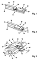
- Fig. 1
- eine perspektivische Darstellung eines Endes eines Wischblatts mit einem zu montierenden Basiselement,
- Fig. 2
- ein Wischblattende nach
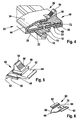
Fig. 1 mit montiertem Basiselement, - Fig. 3
- ein Wischblattende nach
Fig. 2 mit einem halbmontierten Spitzenhalter, - Fig. 4
- einen Schnitt entsprechend der Linie IV-IV in
Fig. 3 , - Fig. 5
- eine perspektivische Darstellung eines Spitzenhalters,
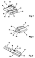
- Fig. 6
- eine perspektivische Darstellung eines Spitzenblechs,
- Fig. 7
- einen Spitzenhalter mit einem montierten Spitzenblech,
- Fig. 8
- eine perspektivische Darstellung einer Abdeckkappe,
- Fig. 9
- ein Wischblattende mit einer halbmontierten Abdeckkappe und
- Fig. 10
- ein Wischblattende nach
Fig. 9 mit montierter Abdeckkappe von unten. -
Fig. 1 zeigt das Ende eines Wischblatts 10, das eine Wischleiste 12 und als Tragelement zwei Federschienen 22 besitzt. Diese sind in zwei seitlichen Längsnuten 20 einer Kopfleiste 18 der Wischleiste 12 eingesetzt und an ihren Enden über eine Brücke 24 fest miteinander verbunden. Die Wischleiste 12 besitzt eine Wischlippe 14, die über einen Kippsteg 16 mit der Kopfleiste 18 verbunden ist. Am Ende des Wischblatts 10 ist ein Wischblattabschluss 25 vorgesehen, der ein Basiselement 26 und einen Spitzenhalter 40 umfasst. Das Basiselement 26, das ein flaches Querschnittprofil aufweist, wird vom Ende des Wischblatts 10 her auf die Federschienen 22 aufgeschoben und zwischen Längsflansche 36 und einer Deckwand 34 geführt. In der Deckwand 34 befindet sich eine Rastöffnung 28, die der Kontur der Brücke 24 angepasst ist und die bei der Montage mit der Brücke 24 verrastet. Die Brücke 24 kann in montiertem Zustand im Wesentlichen bündig mit der Außenkontur der Deckwand 34 abschließen, sodass es ein harmonisches Design ergibt. - Außerdem besitzt das Basiselement 26 eine seitliche Öffnung 30, in die der Spitzenhalter 40 eingesetzt wird. Hierzu dienen an den Rändern der Öffnung 30 Führungsschienen 32, die in seitliche Führungsnuten 48 an einem Führungsblock 46 des Spitzenhalters 40 eingreifen. Der Spitzenhalter 40 wird in seiner Endposition durch eine Raste 42 fixiert, die am Führungsblock 46 angeformt ist und mit einer Rastkante 44 in eine Rastkerbe 38 an der Innenseite der Deckwand 34 eingreift. Grundsätzlich ist es auch möglich, dass die Rastkerbe 38 an dem Spitzenhalter 40 und die Rastkante 44 an dem Basiselement 26 angeordnet sind.
- An der der Wischlippe 14 zugewandten Seite des Spitzenhalters 40 befindet sich ein Einschubfach für ein Spitzenblech 60. Es wird im Wesentlichen durch zwei in einem Abstand einander gegenüberliegenden Führungsnuten 58 gebildet. Diese nehmen an dem Spitzenblech 60 seitlich angeformte Führungswangen 62 auf. Das Spitzenblech 60 wird in die Führungsnuten 58 so eingesetzt, dass seine Spitze 66 zur Wischleiste 12 weist. Die Spitze 66 wird zum Boden 64 des Spitzenblechs 60 durch Anschlagflächen 68 begrenzt. Das Spitzenblech 60 wird zweckmäßigerweise aus einem Stahlblech in einem Blechbiege- und Stanzverfahren hergestellt, wobei in den Boden 64 ein Rastloch 70 gestanzt wird, das mit einem Rastzapfen 72 zusammenwirkt, der an der dem Spitzenblech 60 zugewandten Seite des Führungsblocks 46 zwischen den Führungsnuten 58 angeordnet ist. Das Stahlblech ermöglicht eine flache, und doch stabile Gestaltung des Spitzenblechs 60, wobei die Spitze 66 als Lanzette geformt sein kann. Wenn das Spitzenblech 60 in dem Spitzenhalter 40 montiert ist, steht seine Spitze 66 ein Stück weit über die Führungsnuten 58 vor, sodass die Spitze 66 bei der Montage oberhalb der Federschienen 22 in einen Längssteg zwischen den Längsnuten 20 der Kopfleiste 18 eindringt. Dadurch wird die Wischleiste 12 über den Wischleistenabschluss 25 relativ zu den Federschienen 22 fixiert. Die zugeordnete Federschiene 22 wird im Bereich des Spitzenhalters 40 an ihrer Längsseite von einer Abschlusswand 52 überdeckt, die an dem Spitzenhalter 40 angeformt ist. Zur besseren Führung des Spitzenhalters 40 befinden sich im Bereich der Abschlusswand 52 Führungsstege 50, die in entsprechende Nuten des Basiselements 26 eingreifen.
- Zum Entriegeln des Spitzenhalters 40 besitzt dieser eine Taste 54 mit einer Grifffläche 56. Mit dieser Taste 54 kann die Rastkante 44 aus der Rastkerbe 38 gedrückt werden, sodass der Spitzenhalter 40 entgegen der Montagerichtung aus dem Basiselement 26 geschoben werden kann. Gleichzeitig wird die Spitze 66 des Spitzenblechs 60 aus der Wischleiste 12 entfernt, sodass diese aus dem Zwischenraum zwischen den Federschienen 22 herausgezogen werden kann. Besitzt das Wischblatt 10 einen Spoiler, der nicht dargestellt ist, umfasst der Wischleistenabschluss 25 zweckmäßigerweise eine Abdeckkappe 74, die mit Führungsprofilen 78 auf dem Basiselement 26 geführt ist und mit Rastelementen in Form von Rastkerben 82 in den unteren Schenkeln 80 der Führungsprofile 78 und Rastnocken 84 am Basiselement 26 fixiert ist. Die Abdeckkappe 74 besitzt auf ihrer Anströmseite ein Windleitprofil 76, das dem Windleitprofil des Spoilers angeglichen ist. Ferner ist an der offenen Stirnseite, die einer nach außen gerichteten geschlossenen Stirnwand 86 der Abdeckkappe 74 entgegengesetzt gerichtet ist, ein Anschlussprofil 88 vorgesehen, das einen harmonischen, strömungsgünstigen Übergang zwischen dem Ende des Spoilers und der Abdeckkappe 74 gewährleistet. Im Bereich der höchsten Erhebung des Windleitprofils 76 ist zweckmäßigerweise die Taste 54 angeordnet. Sie wird der Innenkontur der Abdeckkappe 74 so angepasst, dass die Außenkontur, insbesondere das Windleitprofil 76, durch die Taste 54 nicht beeinträchtigt wird.
Claims (10)
- Wischblatt (10) mit einer Wischleiste (12) und zwei als Tragelement dienenden Federschienen (22), die in seitliche Längsnuten (20) der Wischleiste (12) eingesetzt und an ihren Enden durch eine Brücke (24) miteinander fest verbunden sind, wobei am Ende des Wischblatts (10) ein Wischblattabschluss (25) vorgesehen ist, dessen Basiselement (26) auf den Federschienen (22) geführt sowie relativ zu den Federschienen (22) fixiert ist und einen Spitzenhalter (40) aufweist, dessen Spitze (66) in die Wischleiste (12) im montierten Zustand eingreift und die Wischleiste (12) relativ zu den Federschienen (22) fixiert, and das Basiselement (26) in seiner Deckwand (34) eine Rastöffnung (28) aufweist, die mit der Brücke (24) bei der Montage verrastet, dadurch gekennzeichnet, daß das Basiselement eine seitliche Öffnung (30) besitzt, in die der Spitzenhalter (40) eingeführt werden kann und in der Endposition am Basiselement (26) verrastet, wobei die Spitze (66) seitlich in die Wischleiste (12) eindringt.
- Wischblatt (10) nach Anspruch 1, dadurch gekennzeichnet, dass der Spitzenhalter (40) einen Führungsblock (46) mit seitlichen Führungsnuten (48) besitzt, die zu Führungsstegen (50) am Rande der seitlichen Öffnung (30) passen.
- Wischblatt (10) nach Anspruch 2, dadurch gekennzeichnet, dass an dem Führungsblock (46) in Montagerichtung eine Raste (42) angeformt ist, die im montierten Zustand mit einer Rastkante (44) in eine Rastkerbe (38) an der Innenseite der Deckwand (34) einrastet.
- Wischblatt (10) nach einem der Ansprüche 2 oder 3, dadurch gekennzeichnet, dass sich auf der Innenseite des Führungsblocks (46) zwischen zwei Führungsnuten (58) ein Einschubfach für ein Spitzenblech (60) befindet, dessen Spitze (66) der Wischleiste (12) zugewandt ist.
- Wischblatt (10) nach Anspruch 4, dadurch gekennzeichnet, dass das Spitzenblech (60) in seinem Boden (64) ein Rastelement (70) aufweist, das mit einem entsprechenden Rastelement (84) am Spitzenhalter (40) verrastet.
- Wischblatt (10) nach einem der Ansprüche 2 bis 5, dadurch gekennzeichnet, dass am Führungsblock (46) eine Taste (54) zum Lösen der Raste (42) angeordnet ist.
- Wischblatt (10) nach einem der vorhergehenden Ansprüche, dadurch gekennzeichnet, dass eine Abdeckkappe (74) das Basiselement (26) und den Spitzenhalter (40) überdeckt, die mit Führungsprofilen (78) auf dem Basiselement (26) geführt ist und am Ende eine geschlossene Stirnwand (86) besitzt.
- Wischblatt (10) nach Anspruch 7, dadurch gekennzeichnet, dass die Abdeckkappe (74) an ihrer Anströmseite ein Windleitprofil (76) und an ihrer offenen Stirnseite ein Anschlussprofil (88) zum Anschluss an einen Spoiler besitzt.
- Wischblatt (10) nach Anspruch 7, dadurch gekennzeichnet, dass die Taste (54) im Bereich der höchsten Erhebung des Windleitprofils (76) angeordnet und der Innenkontur der Abdeckkappe (74) anpasst ist.
- Wischblatt (10) nach einem der Ansprüche 7 bis 9, dadurch gekennzeichnet, dass an den unteren Schenkeln (80) der Führungsprofile (78) Rastelemente (82) vorgesehen sind, die mit Rastelementen (84) an dem Basiselement (26) zusammenwirken.
Priority Applications (1)
| Application Number | Priority Date | Filing Date | Title |
|---|---|---|---|
| PL08786132T PL2190703T3 (pl) | 2007-09-12 | 2008-07-14 | Pióro wycieraczki |
Applications Claiming Priority (2)
| Application Number | Priority Date | Filing Date | Title |
|---|---|---|---|
| DE102007043528A DE102007043528A1 (de) | 2007-09-12 | 2007-09-12 | Wischblatt |
| PCT/EP2008/059176 WO2009033854A1 (de) | 2007-09-12 | 2008-07-14 | Wischblatt |
Publications (2)
| Publication Number | Publication Date |
|---|---|
| EP2190703A1 EP2190703A1 (de) | 2010-06-02 |
| EP2190703B1 true EP2190703B1 (de) | 2012-06-20 |
Family
ID=39691299
Family Applications (1)
| Application Number | Title | Priority Date | Filing Date |
|---|---|---|---|
| EP08786132A Not-in-force EP2190703B1 (de) | 2007-09-12 | 2008-07-14 | Wischblatt |
Country Status (11)
| Country | Link |
|---|---|
| US (1) | US8375503B2 (de) |
| EP (1) | EP2190703B1 (de) |
| JP (1) | JP5006969B2 (de) |
| KR (1) | KR101489192B1 (de) |
| CN (1) | CN101801742B (de) |
| BR (1) | BRPI0817080B1 (de) |
| DE (1) | DE102007043528A1 (de) |
| ES (1) | ES2385769T3 (de) |
| PL (1) | PL2190703T3 (de) |
| RU (1) | RU2468941C2 (de) |
| WO (1) | WO2009033854A1 (de) |
Families Citing this family (25)
| Publication number | Priority date | Publication date | Assignee | Title |
|---|---|---|---|---|
| DE102010042096A1 (de) * | 2009-10-09 | 2011-04-14 | Robert Bosch Gmbh | Wischblatt |
| US8495787B2 (en) | 2010-08-03 | 2013-07-30 | Rally Manufacturing, Inc. | Windshield wiper |
| WO2012114596A1 (ja) * | 2011-02-23 | 2012-08-30 | 株式会社ミツバ | ワイパブレード |
| FR2973313B1 (fr) * | 2011-03-31 | 2013-05-03 | Valeo Systemes Dessuyage | Partie primaire et partie secondaire d'un embout d'extremite pour balai d'essuyage |
| FR2973312B1 (fr) * | 2011-03-31 | 2013-05-03 | Valeo Systemes Dessuyage | Embout d'extremite pour balai d'essuyage |
| US9457768B2 (en) | 2011-04-21 | 2016-10-04 | Pylon Manufacturing Corp. | Vortex damping wiper blade |
| DE102011078168A1 (de) * | 2011-06-28 | 2013-01-03 | Robert Bosch Gmbh | Wischblattvorrichtung |
| MX345011B (es) | 2011-07-28 | 2017-01-11 | Pylon Mfg Corp | Adaptador, conector y conjunto de limpiaparabrisas. |
| US9108595B2 (en) | 2011-07-29 | 2015-08-18 | Pylon Manufacturing Corporation | Windshield wiper connector |
| BR112014014034A2 (pt) * | 2011-12-14 | 2017-06-13 | Federal Mogul Sa | dispositivo limpador de para-brisa |
| CN103171523B (zh) * | 2011-12-26 | 2015-04-22 | 宁波汉德汽车配件有限公司 | 软骨雨刮片 |
| US20130219649A1 (en) | 2012-02-24 | 2013-08-29 | Pylon Manufacturing Corp. | Wiper blade |
| US10723322B2 (en) | 2012-02-24 | 2020-07-28 | Pylon Manufacturing Corp. | Wiper blade with cover |
| CA2865292C (en) | 2012-02-24 | 2018-03-13 | Pylon Manufacturing Corp. | Wiper blade |
| US10829092B2 (en) | 2012-09-24 | 2020-11-10 | Pylon Manufacturing Corp. | Wiper blade with modular mounting base |
| US10166951B2 (en) | 2013-03-15 | 2019-01-01 | Pylon Manufacturing Corp. | Windshield wiper connector |
| DE102013226036A1 (de) * | 2013-11-05 | 2015-05-07 | Robert Bosch Gmbh | Endkappenvorrichtung |
| US9505380B2 (en) | 2014-03-07 | 2016-11-29 | Pylon Manufacturing Corp. | Windshield wiper connector and assembly |
| IL233429A (en) * | 2014-06-26 | 2017-11-30 | Dan Tyroler | mop |
| WO2017075066A1 (en) | 2015-10-26 | 2017-05-04 | Pylon Manufacturing Corp. | Wiper blade |
| WO2017201458A1 (en) | 2016-05-19 | 2017-11-23 | Pylon Manufacturing Corp. | Windshield wiper connector |
| EP3458315B1 (de) | 2016-05-19 | 2021-09-08 | Pylon Manufacturing Corp. | Scheibenwischerblatt |
| US11040705B2 (en) | 2016-05-19 | 2021-06-22 | Pylon Manufacturing Corp. | Windshield wiper connector |
| AU2017268008A1 (en) | 2016-05-19 | 2018-11-22 | Pylon Manufacturing Corp. | Windshield wiper connector |
| US10766462B2 (en) | 2016-05-19 | 2020-09-08 | Pylon Manufacturing Corporation | Windshield wiper connector |
Family Cites Families (16)
| Publication number | Priority date | Publication date | Assignee | Title |
|---|---|---|---|---|
| US3041654A (en) * | 1957-03-25 | 1962-07-03 | John W Anderson | Windshield wiper blade |
| IT1244564B (it) * | 1990-09-24 | 1994-07-28 | Champion Spark Plug Divisione | Spatola tergicristallo monostruttura e relativo procedimento di fabbricazione |
| DE19811702A1 (de) * | 1998-03-18 | 1999-09-23 | Itt Mfg Enterprises Inc | Wischblatt und Austauschsatz für ein Wischblatt |
| DE19856300A1 (de) * | 1998-12-07 | 2000-06-08 | Bosch Gmbh Robert | Wischblatt für Scheiben von Kraftfahrzeugen |
| DE19906288A1 (de) * | 1999-02-15 | 2000-08-17 | Bosch Gmbh Robert | Vorrichtung zum gelenkigen Verbinden eines Wischblatts für Scheiben von Kraftfahrzeugen mit einem Wischerarm |
| DE10139104A1 (de) * | 2001-08-09 | 2003-03-06 | Valeo Auto Electric Gmbh | Wischblatt, insbesondere Flachwischblatt |
| DE10245693A1 (de) | 2002-09-30 | 2004-04-08 | Robert Bosch Gmbh | Vorrichtung mit einem federelastischen Tragmittel für eine Wischleiste |
| DE10259478A1 (de) * | 2002-12-19 | 2004-07-01 | Robert Bosch Gmbh | Wischvorrichtung für Scheiben von Kraftfahrzeugen |
| DE102004015423A1 (de) * | 2004-03-26 | 2005-10-13 | Robert Bosch Gmbh | Wischblatt |
| DE102004019157A1 (de) * | 2004-04-21 | 2005-11-10 | Robert Bosch Gmbh | Wischblatt |
| DE102004051466A1 (de) * | 2004-05-28 | 2005-12-15 | Robert Bosch Gmbh | Wischblatt |
| DE102004051467A1 (de) * | 2004-05-28 | 2005-12-15 | Robert Bosch Gmbh | Wischblatt |
| KR100633643B1 (ko) * | 2004-11-24 | 2006-10-11 | 현대자동차주식회사 | 러버 교체가 가능한 자동차 와이퍼 블레이드의 엔드 클립 |
| DE602005009653D1 (de) * | 2005-03-02 | 2008-10-23 | Federal Mogul Sa | Scheibenwischervorrichtung |
| FR2893290B1 (fr) * | 2005-09-13 | 2009-05-01 | Valeo Systemes Dessuyage | Dispositif de verrouillage entre une lame d'essuyage et un porte-balai d'essuie-glace |
| EP2054276B1 (de) * | 2006-08-18 | 2017-07-12 | Robert Bosch GmbH | Wischblatt mit stützelement |
-
2007
- 2007-09-12 DE DE102007043528A patent/DE102007043528A1/de not_active Withdrawn
-
2008
- 2008-07-14 PL PL08786132T patent/PL2190703T3/pl unknown
- 2008-07-14 EP EP08786132A patent/EP2190703B1/de not_active Not-in-force
- 2008-07-14 BR BRPI0817080-0A patent/BRPI0817080B1/pt not_active IP Right Cessation
- 2008-07-14 JP JP2010524425A patent/JP5006969B2/ja not_active Expired - Fee Related
- 2008-07-14 ES ES08786132T patent/ES2385769T3/es active Active
- 2008-07-14 KR KR1020107004897A patent/KR101489192B1/ko active IP Right Grant
- 2008-07-14 WO PCT/EP2008/059176 patent/WO2009033854A1/de active Application Filing
- 2008-07-14 CN CN2008801065190A patent/CN101801742B/zh not_active Expired - Fee Related
- 2008-07-14 US US12/669,822 patent/US8375503B2/en not_active Expired - Fee Related
- 2008-07-14 RU RU2010113720/11A patent/RU2468941C2/ru not_active IP Right Cessation
Also Published As
| Publication number | Publication date |
|---|---|
| EP2190703A1 (de) | 2010-06-02 |
| CN101801742A (zh) | 2010-08-11 |
| US20100180395A1 (en) | 2010-07-22 |
| ES2385769T3 (es) | 2012-07-31 |
| JP2010538893A (ja) | 2010-12-16 |
| KR101489192B1 (ko) | 2015-02-03 |
| RU2468941C2 (ru) | 2012-12-10 |
| WO2009033854A1 (de) | 2009-03-19 |
| PL2190703T3 (pl) | 2012-11-30 |
| US8375503B2 (en) | 2013-02-19 |
| KR20100053611A (ko) | 2010-05-20 |
| CN101801742B (zh) | 2012-07-11 |
| RU2010113720A (ru) | 2011-10-20 |
| BRPI0817080A2 (pt) | 2015-03-24 |
| DE102007043528A1 (de) | 2009-03-19 |
| BRPI0817080B1 (pt) | 2019-08-20 |
| JP5006969B2 (ja) | 2012-08-22 |
Similar Documents
| Publication | Publication Date | Title |
|---|---|---|
| EP2190703B1 (de) | Wischblatt | |
| EP1966013B1 (de) | Anschlusselement | |
| EP2424755B1 (de) | Anschlussvorrichtung zum gelenkigen verbinden eines mit einem wischarm fest verbundenen verbindungselements | |
| EP2321160B1 (de) | Vorrichtung zum gelenkigen verbinden eines wischblatts mit einem wischarm eines scheibenwischers | |
| EP2326538B1 (de) | Anschlussvorrichtung zum gelenkigen verbinden eines wischblatts mit einem wischarm | |
| EP1877290B1 (de) | Wischarm mit einem wischblatt | |
| EP2121394B1 (de) | Verbindungselement zum gelenkigen verbinden eines wischblatts mit einem wischarm | |
| EP2477853B1 (de) | Wischblatt in flachbalkenbauweise | |
| DE102010041152A1 (de) | Adapter zum Verbinden eines Verbindungselements am Ende eines Wischarms mit einem Wischblatt insbesondere in Flachbalkenbauweise | |
| WO2011042518A1 (de) | Wischblatt | |
| EP2162321A1 (de) | Flaches wischblatt | |
| DE102006061680A1 (de) | Wischblatt | |
| EP2450244A1 (de) | Wischblatt | |
| WO2010017861A1 (de) | Scheibenwischer an einem fahrzeug | |
| EP2714476A1 (de) | Wischblatt | |
| DE102011003838A1 (de) | Vorrichtung zum gelenkigen Verbinden eines Wischblatts in Flachbalkenbauweise mit einem Wischarm | |
| EP2177407A1 (de) | Wischblatt | |
| EP2097298B1 (de) | Wischblatt | |
| DE102008040033A1 (de) | Baureihe eines Wischblatts | |
| EP2214936B1 (de) | Wischblatt | |
| DE102005020601A1 (de) | Vorrichtung zum gelenkigen Verbinden eines Wischblatts mit einem Wischarm |
Legal Events
| Date | Code | Title | Description |
|---|---|---|---|
| PUAI | Public reference made under article 153(3) epc to a published international application that has entered the european phase |
Free format text: ORIGINAL CODE: 0009012 |
|
| 17P | Request for examination filed |
Effective date: 20100412 |
|
| AK | Designated contracting states |
Kind code of ref document: A1 Designated state(s): AT BE BG CH CY CZ DE DK EE ES FI FR GB GR HR HU IE IS IT LI LT LU LV MC MT NL NO PL PT RO SE SI SK TR |
|
| AX | Request for extension of the european patent |
Extension state: AL BA MK RS |
|
| DAX | Request for extension of the european patent (deleted) | ||
| 17Q | First examination report despatched |
Effective date: 20110926 |
|
| GRAP | Despatch of communication of intention to grant a patent |
Free format text: ORIGINAL CODE: EPIDOSNIGR1 |
|
| GRAS | Grant fee paid |
Free format text: ORIGINAL CODE: EPIDOSNIGR3 |
|
| GRAA | (expected) grant |
Free format text: ORIGINAL CODE: 0009210 |
|
| AK | Designated contracting states |
Kind code of ref document: B1 Designated state(s): AT BE BG CH CY CZ DE DK EE ES FI FR GB GR HR HU IE IS IT LI LT LU LV MC MT NL NO PL PT RO SE SI SK TR |
|
| REG | Reference to a national code |
Ref country code: GB Ref legal event code: FG4D Free format text: NOT ENGLISH |
|
| REG | Reference to a national code |
Ref country code: CH Ref legal event code: EP |
|
| REG | Reference to a national code |
Ref country code: AT Ref legal event code: REF Ref document number: 562874 Country of ref document: AT Kind code of ref document: T Effective date: 20120715 |
|
| REG | Reference to a national code |
Ref country code: IE Ref legal event code: FG4D Free format text: LANGUAGE OF EP DOCUMENT: GERMAN |
|
| REG | Reference to a national code |
Ref country code: ES Ref legal event code: FG2A Ref document number: 2385769 Country of ref document: ES Kind code of ref document: T3 Effective date: 20120731 |
|
| REG | Reference to a national code |
Ref country code: DE Ref legal event code: R096 Ref document number: 502008007507 Country of ref document: DE Effective date: 20120816 |
|
| REG | Reference to a national code |
Ref country code: RO Ref legal event code: EPE |
|
| REG | Reference to a national code |
Ref country code: SE Ref legal event code: TRGR |
|
| REG | Reference to a national code |
Ref country code: NL Ref legal event code: T3 |
|
| PG25 | Lapsed in a contracting state [announced via postgrant information from national office to epo] |
Ref country code: NO Free format text: LAPSE BECAUSE OF FAILURE TO SUBMIT A TRANSLATION OF THE DESCRIPTION OR TO PAY THE FEE WITHIN THE PRESCRIBED TIME-LIMIT Effective date: 20120920 Ref country code: LT Free format text: LAPSE BECAUSE OF FAILURE TO SUBMIT A TRANSLATION OF THE DESCRIPTION OR TO PAY THE FEE WITHIN THE PRESCRIBED TIME-LIMIT Effective date: 20120620 Ref country code: FI Free format text: LAPSE BECAUSE OF FAILURE TO SUBMIT A TRANSLATION OF THE DESCRIPTION OR TO PAY THE FEE WITHIN THE PRESCRIBED TIME-LIMIT Effective date: 20120620 |
|
| REG | Reference to a national code |
Ref country code: LT Ref legal event code: MG4D Effective date: 20120627 |
|
| PG25 | Lapsed in a contracting state [announced via postgrant information from national office to epo] |
Ref country code: LV Free format text: LAPSE BECAUSE OF FAILURE TO SUBMIT A TRANSLATION OF THE DESCRIPTION OR TO PAY THE FEE WITHIN THE PRESCRIBED TIME-LIMIT Effective date: 20120620 Ref country code: GR Free format text: LAPSE BECAUSE OF FAILURE TO SUBMIT A TRANSLATION OF THE DESCRIPTION OR TO PAY THE FEE WITHIN THE PRESCRIBED TIME-LIMIT Effective date: 20120921 Ref country code: SI Free format text: LAPSE BECAUSE OF FAILURE TO SUBMIT A TRANSLATION OF THE DESCRIPTION OR TO PAY THE FEE WITHIN THE PRESCRIBED TIME-LIMIT Effective date: 20120620 Ref country code: HR Free format text: LAPSE BECAUSE OF FAILURE TO SUBMIT A TRANSLATION OF THE DESCRIPTION OR TO PAY THE FEE WITHIN THE PRESCRIBED TIME-LIMIT Effective date: 20120620 |
|
| REG | Reference to a national code |
Ref country code: PL Ref legal event code: T3 |
|
| PG25 | Lapsed in a contracting state [announced via postgrant information from national office to epo] |
Ref country code: CY Free format text: LAPSE BECAUSE OF FAILURE TO SUBMIT A TRANSLATION OF THE DESCRIPTION OR TO PAY THE FEE WITHIN THE PRESCRIBED TIME-LIMIT Effective date: 20120620 Ref country code: EE Free format text: LAPSE BECAUSE OF FAILURE TO SUBMIT A TRANSLATION OF THE DESCRIPTION OR TO PAY THE FEE WITHIN THE PRESCRIBED TIME-LIMIT Effective date: 20120620 Ref country code: IS Free format text: LAPSE BECAUSE OF FAILURE TO SUBMIT A TRANSLATION OF THE DESCRIPTION OR TO PAY THE FEE WITHIN THE PRESCRIBED TIME-LIMIT Effective date: 20121020 Ref country code: SK Free format text: LAPSE BECAUSE OF FAILURE TO SUBMIT A TRANSLATION OF THE DESCRIPTION OR TO PAY THE FEE WITHIN THE PRESCRIBED TIME-LIMIT Effective date: 20120620 |
|
| PG25 | Lapsed in a contracting state [announced via postgrant information from national office to epo] |
Ref country code: PT Free format text: LAPSE BECAUSE OF FAILURE TO SUBMIT A TRANSLATION OF THE DESCRIPTION OR TO PAY THE FEE WITHIN THE PRESCRIBED TIME-LIMIT Effective date: 20121022 Ref country code: MC Free format text: LAPSE BECAUSE OF NON-PAYMENT OF DUE FEES Effective date: 20120731 |
|
| REG | Reference to a national code |
Ref country code: CH Ref legal event code: PL |
|
| PLBE | No opposition filed within time limit |
Free format text: ORIGINAL CODE: 0009261 |
|
| STAA | Information on the status of an ep patent application or granted ep patent |
Free format text: STATUS: NO OPPOSITION FILED WITHIN TIME LIMIT |
|
| PG25 | Lapsed in a contracting state [announced via postgrant information from national office to epo] |
Ref country code: LI Free format text: LAPSE BECAUSE OF NON-PAYMENT OF DUE FEES Effective date: 20120731 Ref country code: DK Free format text: LAPSE BECAUSE OF FAILURE TO SUBMIT A TRANSLATION OF THE DESCRIPTION OR TO PAY THE FEE WITHIN THE PRESCRIBED TIME-LIMIT Effective date: 20120620 Ref country code: CH Free format text: LAPSE BECAUSE OF NON-PAYMENT OF DUE FEES Effective date: 20120731 |
|
| REG | Reference to a national code |
Ref country code: IE Ref legal event code: MM4A |
|
| 26N | No opposition filed |
Effective date: 20130321 |
|
| REG | Reference to a national code |
Ref country code: HU Ref legal event code: AG4A Ref document number: E015369 Country of ref document: HU |
|
| REG | Reference to a national code |
Ref country code: DE Ref legal event code: R097 Ref document number: 502008007507 Country of ref document: DE Effective date: 20130321 |
|
| PG25 | Lapsed in a contracting state [announced via postgrant information from national office to epo] |
Ref country code: BG Free format text: LAPSE BECAUSE OF FAILURE TO SUBMIT A TRANSLATION OF THE DESCRIPTION OR TO PAY THE FEE WITHIN THE PRESCRIBED TIME-LIMIT Effective date: 20120920 Ref country code: MT Free format text: LAPSE BECAUSE OF FAILURE TO SUBMIT A TRANSLATION OF THE DESCRIPTION OR TO PAY THE FEE WITHIN THE PRESCRIBED TIME-LIMIT Effective date: 20120620 Ref country code: IE Free format text: LAPSE BECAUSE OF NON-PAYMENT OF DUE FEES Effective date: 20120714 |
|
| PG25 | Lapsed in a contracting state [announced via postgrant information from national office to epo] |
Ref country code: TR Free format text: LAPSE BECAUSE OF FAILURE TO SUBMIT A TRANSLATION OF THE DESCRIPTION OR TO PAY THE FEE WITHIN THE PRESCRIBED TIME-LIMIT Effective date: 20120620 |
|
| PG25 | Lapsed in a contracting state [announced via postgrant information from national office to epo] |
Ref country code: LU Free format text: LAPSE BECAUSE OF NON-PAYMENT OF DUE FEES Effective date: 20120714 |
|
| REG | Reference to a national code |
Ref country code: AT Ref legal event code: MM01 Ref document number: 562874 Country of ref document: AT Kind code of ref document: T Effective date: 20130714 |
|
| PG25 | Lapsed in a contracting state [announced via postgrant information from national office to epo] |
Ref country code: AT Free format text: LAPSE BECAUSE OF NON-PAYMENT OF DUE FEES Effective date: 20130714 |
|
| REG | Reference to a national code |
Ref country code: FR Ref legal event code: PLFP Year of fee payment: 9 |
|
| REG | Reference to a national code |
Ref country code: FR Ref legal event code: PLFP Year of fee payment: 10 |
|
| REG | Reference to a national code |
Ref country code: FR Ref legal event code: PLFP Year of fee payment: 11 |
|
| PGFP | Annual fee paid to national office [announced via postgrant information from national office to epo] |
Ref country code: NL Payment date: 20190722 Year of fee payment: 12 |
|
| PGFP | Annual fee paid to national office [announced via postgrant information from national office to epo] |
Ref country code: DE Payment date: 20190924 Year of fee payment: 12 Ref country code: FR Payment date: 20190724 Year of fee payment: 12 Ref country code: CZ Payment date: 20190704 Year of fee payment: 12 Ref country code: RO Payment date: 20190710 Year of fee payment: 12 Ref country code: IT Payment date: 20190723 Year of fee payment: 12 Ref country code: ES Payment date: 20190822 Year of fee payment: 12 Ref country code: SE Payment date: 20190725 Year of fee payment: 12 |
|
| PGFP | Annual fee paid to national office [announced via postgrant information from national office to epo] |
Ref country code: HU Payment date: 20190702 Year of fee payment: 12 Ref country code: BE Payment date: 20190722 Year of fee payment: 12 Ref country code: PL Payment date: 20190705 Year of fee payment: 12 |
|
| PGFP | Annual fee paid to national office [announced via postgrant information from national office to epo] |
Ref country code: GB Payment date: 20190725 Year of fee payment: 12 |
|
| REG | Reference to a national code |
Ref country code: DE Ref legal event code: R119 Ref document number: 502008007507 Country of ref document: DE |
|
| REG | Reference to a national code |
Ref country code: SE Ref legal event code: EUG |
|
| REG | Reference to a national code |
Ref country code: NL Ref legal event code: MM Effective date: 20200801 |
|
| GBPC | Gb: european patent ceased through non-payment of renewal fee |
Effective date: 20200714 |
|
| REG | Reference to a national code |
Ref country code: BE Ref legal event code: MM Effective date: 20200731 |
|
| PG25 | Lapsed in a contracting state [announced via postgrant information from national office to epo] |
Ref country code: GB Free format text: LAPSE BECAUSE OF NON-PAYMENT OF DUE FEES Effective date: 20200714 Ref country code: FR Free format text: LAPSE BECAUSE OF NON-PAYMENT OF DUE FEES Effective date: 20200731 Ref country code: RO Free format text: LAPSE BECAUSE OF NON-PAYMENT OF DUE FEES Effective date: 20200714 Ref country code: NL Free format text: LAPSE BECAUSE OF NON-PAYMENT OF DUE FEES Effective date: 20200801 Ref country code: CZ Free format text: LAPSE BECAUSE OF NON-PAYMENT OF DUE FEES Effective date: 20200714 Ref country code: HU Free format text: LAPSE BECAUSE OF NON-PAYMENT OF DUE FEES Effective date: 20200715 |
|
| PG25 | Lapsed in a contracting state [announced via postgrant information from national office to epo] |
Ref country code: BE Free format text: LAPSE BECAUSE OF NON-PAYMENT OF DUE FEES Effective date: 20200731 Ref country code: DE Free format text: LAPSE BECAUSE OF NON-PAYMENT OF DUE FEES Effective date: 20210202 Ref country code: SE Free format text: LAPSE BECAUSE OF NON-PAYMENT OF DUE FEES Effective date: 20200715 |
|
| PG25 | Lapsed in a contracting state [announced via postgrant information from national office to epo] |
Ref country code: IT Free format text: LAPSE BECAUSE OF NON-PAYMENT OF DUE FEES Effective date: 20200714 |
|
| REG | Reference to a national code |
Ref country code: ES Ref legal event code: FD2A Effective date: 20211230 |
|
| PG25 | Lapsed in a contracting state [announced via postgrant information from national office to epo] |
Ref country code: ES Free format text: LAPSE BECAUSE OF NON-PAYMENT OF DUE FEES Effective date: 20200715 |
|
| PG25 | Lapsed in a contracting state [announced via postgrant information from national office to epo] |
Ref country code: PL Free format text: LAPSE BECAUSE OF NON-PAYMENT OF DUE FEES Effective date: 20200714 |