EP1964063B1 - Verfahren zum konfigurieren einer überwachungseinrichtung zum überwachen eines raumbereichs - Google Patents
Verfahren zum konfigurieren einer überwachungseinrichtung zum überwachen eines raumbereichs Download PDFInfo
- Publication number
- EP1964063B1 EP1964063B1 EP06829542.7A EP06829542A EP1964063B1 EP 1964063 B1 EP1964063 B1 EP 1964063B1 EP 06829542 A EP06829542 A EP 06829542A EP 1964063 B1 EP1964063 B1 EP 1964063B1
- Authority
- EP
- European Patent Office
- Prior art keywords
- image
- configuration
- spatial
- spatial area
- monitoring
- Prior art date
- Legal status (The legal status is an assumption and is not a legal conclusion. Google has not performed a legal analysis and makes no representation as to the accuracy of the status listed.)
- Active
Links
- 238000012544 monitoring process Methods 0.000 title claims description 46
- 238000000034 method Methods 0.000 title claims description 35
- 238000012806 monitoring device Methods 0.000 claims description 54
- 230000009466 transformation Effects 0.000 claims description 6
- 238000004590 computer program Methods 0.000 claims description 5
- 238000004891 communication Methods 0.000 claims description 3
- 238000011156 evaluation Methods 0.000 description 25
- 230000004888 barrier function Effects 0.000 description 10
- 231100001261 hazardous Toxicity 0.000 description 5
- 230000001681 protective effect Effects 0.000 description 5
- 238000012545 processing Methods 0.000 description 4
- 238000013475 authorization Methods 0.000 description 3
- 230000008901 benefit Effects 0.000 description 3
- 230000005540 biological transmission Effects 0.000 description 3
- 238000004422 calculation algorithm Methods 0.000 description 3
- 230000006870 function Effects 0.000 description 3
- 238000005259 measurement Methods 0.000 description 3
- 208000003443 Unconsciousness Diseases 0.000 description 2
- 208000027418 Wounds and injury Diseases 0.000 description 2
- 230000006978 adaptation Effects 0.000 description 2
- 238000004458 analytical method Methods 0.000 description 2
- 230000008859 change Effects 0.000 description 2
- 230000006378 damage Effects 0.000 description 2
- 238000013461 design Methods 0.000 description 2
- 238000001514 detection method Methods 0.000 description 2
- 238000011990 functional testing Methods 0.000 description 2
- 208000014674 injury Diseases 0.000 description 2
- 238000003780 insertion Methods 0.000 description 2
- 230000037431 insertion Effects 0.000 description 2
- 238000009434 installation Methods 0.000 description 2
- 230000007246 mechanism Effects 0.000 description 2
- 230000008569 process Effects 0.000 description 2
- 238000001454 recorded image Methods 0.000 description 2
- 238000012360 testing method Methods 0.000 description 2
- 238000004364 calculation method Methods 0.000 description 1
- 238000011109 contamination Methods 0.000 description 1
- 230000006735 deficit Effects 0.000 description 1
- 238000003384 imaging method Methods 0.000 description 1
- 230000008676 import Effects 0.000 description 1
- 238000002955 isolation Methods 0.000 description 1
- 238000000691 measurement method Methods 0.000 description 1
- 238000012986 modification Methods 0.000 description 1
- 230000004048 modification Effects 0.000 description 1
- 238000000275 quality assurance Methods 0.000 description 1
- 238000003908 quality control method Methods 0.000 description 1
- 238000012552 review Methods 0.000 description 1
- 239000000725 suspension Substances 0.000 description 1
- 230000001960 triggered effect Effects 0.000 description 1
- 238000012795 verification Methods 0.000 description 1
- 230000000007 visual effect Effects 0.000 description 1
- XLYOFNOQVPJJNP-UHFFFAOYSA-N water Substances O XLYOFNOQVPJJNP-UHFFFAOYSA-N 0.000 description 1
Images


Classifications
-
- F—MECHANICAL ENGINEERING; LIGHTING; HEATING; WEAPONS; BLASTING
- F16—ENGINEERING ELEMENTS AND UNITS; GENERAL MEASURES FOR PRODUCING AND MAINTAINING EFFECTIVE FUNCTIONING OF MACHINES OR INSTALLATIONS; THERMAL INSULATION IN GENERAL
- F16P—SAFETY DEVICES IN GENERAL; SAFETY DEVICES FOR PRESSES
- F16P3/00—Safety devices acting in conjunction with the control or operation of a machine; Control arrangements requiring the simultaneous use of two or more parts of the body
-
- G—PHYSICS
- G06—COMPUTING; CALCULATING OR COUNTING
- G06T—IMAGE DATA PROCESSING OR GENERATION, IN GENERAL
- G06T7/00—Image analysis
- G06T7/0002—Inspection of images, e.g. flaw detection
- G06T7/0004—Industrial image inspection
- G06T7/0008—Industrial image inspection checking presence/absence
-
- F—MECHANICAL ENGINEERING; LIGHTING; HEATING; WEAPONS; BLASTING
- F16—ENGINEERING ELEMENTS AND UNITS; GENERAL MEASURES FOR PRODUCING AND MAINTAINING EFFECTIVE FUNCTIONING OF MACHINES OR INSTALLATIONS; THERMAL INSULATION IN GENERAL
- F16P—SAFETY DEVICES IN GENERAL; SAFETY DEVICES FOR PRESSES
- F16P3/00—Safety devices acting in conjunction with the control or operation of a machine; Control arrangements requiring the simultaneous use of two or more parts of the body
- F16P3/12—Safety devices acting in conjunction with the control or operation of a machine; Control arrangements requiring the simultaneous use of two or more parts of the body with means, e.g. feelers, which in case of the presence of a body part of a person in or near the danger zone influence the control or operation of the machine
- F16P3/14—Safety devices acting in conjunction with the control or operation of a machine; Control arrangements requiring the simultaneous use of two or more parts of the body with means, e.g. feelers, which in case of the presence of a body part of a person in or near the danger zone influence the control or operation of the machine the means being photocells or other devices sensitive without mechanical contact
- F16P3/142—Safety devices acting in conjunction with the control or operation of a machine; Control arrangements requiring the simultaneous use of two or more parts of the body with means, e.g. feelers, which in case of the presence of a body part of a person in or near the danger zone influence the control or operation of the machine the means being photocells or other devices sensitive without mechanical contact using image capturing devices
-
- G—PHYSICS
- G06—COMPUTING; CALCULATING OR COUNTING
- G06T—IMAGE DATA PROCESSING OR GENERATION, IN GENERAL
- G06T15/00—3D [Three Dimensional] image rendering
-
- G—PHYSICS
- G06—COMPUTING; CALCULATING OR COUNTING
- G06T—IMAGE DATA PROCESSING OR GENERATION, IN GENERAL
- G06T7/00—Image analysis
- G06T7/50—Depth or shape recovery
- G06T7/55—Depth or shape recovery from multiple images
- G06T7/593—Depth or shape recovery from multiple images from stereo images
-
- H—ELECTRICITY
- H04—ELECTRIC COMMUNICATION TECHNIQUE
- H04N—PICTORIAL COMMUNICATION, e.g. TELEVISION
- H04N13/00—Stereoscopic video systems; Multi-view video systems; Details thereof
- H04N13/20—Image signal generators
- H04N13/204—Image signal generators using stereoscopic image cameras
-
- H—ELECTRICITY
- H04—ELECTRIC COMMUNICATION TECHNIQUE
- H04N—PICTORIAL COMMUNICATION, e.g. TELEVISION
- H04N23/00—Cameras or camera modules comprising electronic image sensors; Control thereof
- H04N23/60—Control of cameras or camera modules
- H04N23/63—Control of cameras or camera modules by using electronic viewfinders
Definitions
- the present invention relates to a method for configuring a monitoring device for monitoring a spatial area, in particular for fail-safe monitoring of the working area of an automatically operating machine or installation.
- the invention further relates to a corresponding monitoring device.
- Photocells, light grids and the like must be aligned and mounted very accurately. In addition, they can each monitor only a straight surface portion between the light emitter and the light receiver, so that a plurality of light barriers, light grids and the like are needed to secure a complex work area all around. In addition, mechanical barriers and conventional light barriers, light curtains and the like have only limited flexibility, so that the adaptation of the monitoring and protection rooms to changing work environments is complex.
- the monitoring device described uses at least two image recording units which record the working area of the machine to be protected at the same time.
- the images of the two image acquisition units are subjected to three-dimensional scene analysis methods with which distance information can be determined. This allows foreign objects entering the hazardous working area of the machine to be detected to shut down or otherwise restore the machine to a safe condition.
- DE 10 2004 020 998 A1 describes another aspect of such a monitoring device, namely an advantageous realization of the imaging optics for the image recording unit.
- a manipulation of the monitoring device by a conscious or unconscious change of the viewing direction of the image recording unit can be detected in this way.
- EP 1 065 522 B1 describes a monitoring device in which the transit times of light pulses are detected with an image acquisition unit in order to obtain a three-dimensional image of the monitored spatial area. By comparison with stored reference values, it can then be determined whether an object has entered the monitored area.
- FIG DE 197 09 799 A1 and DE 101 38 960 A1 Other monitoring devices using image acquisition units are shown in FIG DE 197 09 799 A1 and DE 101 38 960 A1 described.
- the former document proposes a stereoscopic image evaluation in order to generate three-dimensional image signal sets and to compare them with corresponding reference signal sets. Objects can be recognized if the current scene situation deviates from the reference model.
- DE 101 38 960 A1 proposes a method in which distance information is determined based on brightness differences.
- three-dimensional image refers to an image of the spatial region which, in addition to the actual (two-dimensional) image, also contains distance information on individual or all objects in the spatial region.
- the distance information may be obtained, for example, by transit time measurement, stereo image processing, or otherwise.
- Monitoring devices that operate according to this principle require only a small installation and assembly effort, since they can observe the space area from a central location. They are also very flexible, as the individual monitoring areas can be freely defined.
- arbitrarily curved gradients and contours within the three-dimensional image can be defined as "virtual protective fences" or “virtual protective spaces”.
- a safety function is triggered, as is known from protection with protective doors, light barriers, light curtains and the like. Even a change or adaptation of the virtual protection areas during operation of the machine or system is readily possible.
- the high flexibility due to the virtual protection areas causes difficulties in setting up and configuring the monitoring device on a machine or plant.
- the course of the protected area due to the mechanical arrangement of the barriers is readily apparent. However, this does not apply to the monitoring facilities with virtual shelters.
- the location and the exact course of the virtual shelters is a safety-relevant property, that is, it must be ensured that a proposed virtual shelter in reality also exactly where it should run. Otherwise, it could lead to unrecognized intrusions into the hazardous area of the monitored system and thus to serious injuries and personal injury. It must also be ensured that there are no gaps in the virtual protective fence, which is difficult due to the high degree of design freedom and flexibility of the virtual shelters.
- DE 41 13 992 A1 proposes to set up a shelter to place so-called measurement marks on the room positions that are to span a surveillance area. Subsequently, the spatial coordinates of the measurement marks are determined on the basis of the recorded images. The obtained Spatial coordinates span the surveillance area.
- this method of setting up surveillance areas is not optimal because the facility requires physical access to the landmarks. Also revealed DE 41 13 992 Al no mechanisms to ensure a fail-safe configuration of a surveillance area.
- JP 09 282459 A discloses a monitoring device that monitors a space area and a method for setting a three-dimensional surveillance area within the space area.
- the three-dimensional monitoring area is determined on the basis of a two-dimensional image of the spatial area.
- an object of the present invention is to provide a method for configuring a monitoring device of the type described above, with which monitoring areas can be configured as simply and, above all, as fail-safe.
- the present invention can be realized by means of a computer program with program code, which is adapted to perform a method of the type described above, when the computer program is executed on a computer.
- a commercial PC is used in conjunction with such a computer program as a configuration device of the monitoring device described.
- the present invention uses a "true" image of the monitored space area to define the surveillance areas in the displayed image.
- a "frozen" real image of the spatial area is used, that is, a real image stored in the configuration device. This has the advantage that the configuration of the monitoring areas can be carried out in the configuration device without the configuration device being connected to the image recording unit during the configuration. Alternatively, however, it is also possible to make the configuration using a live image of the at least one image pickup unit.
- the invention further includes determining a plurality of spatial points in the real image or on the real image and defining a configuration plane using these spatial points.
- the determination of the spatial points implies that the spatial coordinates of selected and / or identified spatial points of the three-dimensional real image are determined.
- a configuration level using these identified space points, a unique relationship is created between the "virtual" configuration level and the real space area. This relationship makes it possible to define virtual geometry elements that are in a unique and specific relationship to the real spatial area. With the generation and transmission of a corresponding data set to the monitoring device or the evaluation unit of such a monitoring device, the virtual geometric elements are effectively projected into the real spatial area. Due to the configuration level, using the real space points defined, this projection is reversibly unique. Therefore, monitoring areas in the form of the geometry elements can be reliably and safely configured.
- the geometry elements can be graphically displayed in or on the real image of the spatial area on the one hand and represent a clear projection into the real spatial area on the other hand, the new procedure allows a very simple and clear configuration.
- the user can assess the location and extent of the monitoring areas very well in relation to the real machine or system.
- the present invention allows a simple and secure configuration of a monitoring device of the type described above. The above object is therefore completely solved.
- a plurality of setup marks are placed in the space area prior to capturing the three-dimensional image to determine the spatial points in the image.
- the setup marks are patterns with a defined structure that can be recognized clearly and quickly in the image of the space area.
- the use of such setup marks facilitates automatic determination of the space points and thus increases the convenience in configuring the monitoring device.
- the use of defined setup marks helps to avoid errors in the determination and allocation of the spatial points. The configuration of the monitoring device therefore becomes even simpler and safer.
- setup marks are automatically searched in the image and marked with a symbol.
- This embodiment includes a first control option, since the user can check very well on the basis of the (automatically assigned) symbol, whether the Location of the defined setup marks is recognized and accepted by the configuration device. It also simplifies configuration and reduces the time required for configuration.
- setup marks are removed before the startup of the monitoring device.
- This embodiment improves the protection of the monitoring device from conscious or unconscious manipulations, since a (re) configuration without the setup marks is prevented.
- At least three spatial points are determined which do not lie on a common straight line.
- This embodiment allows a free plane selection in relation to the real space area.
- the user can freely define the configuration level in the monitored area. This allows the configuration to be optimally adapted to the individual conditions of a monitored machine or system. Alternatively, however, one or two suspension points of the configuration level could also be fixed, so that the user can only vary the level to a limited extent.
- the configuration level is determined on the basis of the at least three spatial points, and a fourth spatial point is determined that lies outside the configuration level.
- This embodiment makes it easier to define a user coordinate system whose origin lies on or under an object, such as a control cabinet.
- the origin of the coordinate system advantageously becomes the projection of the fourth spatial point into a configuration plane which is determined by the other three space points. This configuration increases flexibility and further simplifies the configuration.
- the configuration level is displayed graphically in the displayed image.
- the configuration level is displayed in the form of a grid or in the form of concentric circles and / or radial lines (starting from the origin of a coordinate system defined in relation to the plane) in the displayed real image of the spatial area.
- visual lines of the image capture unit (s), shadow throws, and other guides for defining the surveillance areas are displayed in the displayed image.
- the insertion of such "artificial" auxiliary elements into the displayed real image facilitates the exact definition of surveillance spaces and in particular helps to realize a complete security.
- variable geometry element is displayed graphically in the displayed image.
- variable geometry elements allows a graphical determination of the monitoring areas, which is particularly simple and convenient.
- the review of the established monitoring areas is possible in this way very quickly and reliably.
- a library is provided with a plurality of predefined geometry elements from which the user can select appropriate geometry elements, thereby further accelerating the configuration of the monitoring device. Furthermore, it is preferred that the user can extend the library with its own geometry elements and / or import geometry elements from common CAD programs.
- the user can switch back and forth in configuration between a 2D view and a 3D view to judge the surveillance areas in different views.
- the geometry element has side surfaces that are perpendicular to the configuration level.
- a plurality of geometric elements are determined and combined with each other.
- a multiplicity of reference marks are placed in the spatial area and recorded with the image, a reference position being determined for each reference mark.
- the reference marks are defined patterns in the space area that are different from the pattern of the setup marks.
- the monitoring unit includes at least a first and a second image recording unit, which are spatially offset from one another and produce a first and a partially offset second image of the spatial region, wherein a common image region of the first and second images is displayed as a three-dimensional image.
- This information is of great advantage for the secure configuration of surveillance areas, because the observation areas of two spatially offset image acquisition units always have a - albeit only slightly offset - viewing angle.
- This embodiment is particularly advantageous when the three-dimensional image is generated using stereoscopic methods.
- it can also be used to advantage in other monitoring devices that use, for example, only for reasons of redundancy, two or more image recording units.
- the dataset defines a portion of the space area that corresponds to the geometry element, wherein an object is inserted into the portion of the space area, and wherein a live image of the object is captured and archived upon insertion into the portion of the space area.
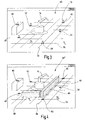
- Fig. 1 an embodiment of a monitoring device according to the present invention is designated in its entirety by the reference numeral 10.
- the monitoring device 10 is used here for monitoring the hazardous working area 12 of a robot 14. It is a preferred application example of the new monitoring device. However, the invention is not limited and can also be used to secure other machinery and equipment.
- the present invention can in principle also be used in other fields, for example for configuring a surveillance area for monitoring valuable objects (vault monitoring, etc.) and / or for monitoring entrance areas in public buildings, at airports etc. It can also be used to configure surveillance areas used in quality control and quality assurance.
- the monitoring device 10 here includes two image recording units 16, 18, which for the sake of simplicity are referred to below as cameras.
- the monitoring device includes three cameras, which together span an approximately equilateral triangle.
- the present invention may also be used with monitoring devices that record a three-dimensional image using transit time measurement techniques or otherwise.
- the cameras 16, 18 record grayscale and / or color images of the monitored spatial area. In principle, however, the cameras 16, 18 can also record infrared images or images in another wavelength range.
- the reference numeral 20 designates an evaluation unit which receives and evaluates the images of the cameras 16, 18 in order to shut down the robot 14 in dependence thereon. Accordingly, the evaluation unit 20 is connected to the robot 14 via a connection 22.
- the evaluation unit 20 may be part of the operation control of the robot 14. However, this is preferably a separate evaluation unit, which alone takes over the safety-related monitoring of the robot. The operation control (not shown here) of the robot 14 is then implemented separately.
- the reference numeral 24 denotes a configuration device with the aid of which the monitoring device 10 can be configured.
- the configuration device includes a conventional PC 26 with a display 28.
- the PC 26 is connected to the evaluation unit 20 via a data connection 29.
- the data connection 29 is an Ethernet connection or a SafetyBus® connection.
- the latter is a fieldbus system developed by the present Applicant specifically developed for safety applications.
- the configuration device 24 is integrated in the evaluation unit 20.
- the communication interface between the evaluation unit and the configuration device in this case is an internal interface between the two functional units, which may be, for example, a software interface.
- an image 30 of the monitored space area 12 is shown on the display 28, an image 30 of the monitored space area 12 is shown. According to a preferred exemplary embodiment, this is a "frozen" real image of the spatial area 12 recorded with the cameras 16, 18.
- the configuration of the surveillance areas in the preferred exemplary embodiment takes place by means of graphically created geometric elements which are superimposed on the image 30 (see FIG 3 and 4 ).
- the reference numerals 32, 34, the receiving areas of the cameras 16, 18 are shown symbolically. As can be readily appreciated, the receiving areas 32, 34 of the two cameras 16, 18 are slightly offset from one another and there is a common, overlapping receiving area, which is designated by the reference numeral 36. The configuration and monitoring of the spatial area advantageously takes place only for the common receiving area 36.
- the reference numeral 38 denotes a first monitoring area, which is referred to below as the warning area.
- Reference numeral 40 denotes a second monitoring area, hereinafter referred to as a guard or stop area.
- the monitoring areas 38, 40 form a virtual fence that prevents unnoticed intrusion of a person 42 in the work area 12 of the robot 14. As shown by the warning area 38, this fence can "float", ie it does not necessarily rest on the ground.
- FIG. 2 shows the location of the warning and protection area 38, 40 from above. As shown, the two areas surround the working area of the robot 12 approximately semicircular. The exposed part of the working area 12 may be secured by mechanical barriers, for example (not shown here). It is understood that the monitoring areas 38, 40 can also completely surround the working area 12 of the robot 14 or have a different course.
- Reference numerals 46, 48, 50 designate three setup marks that are laid out on the floor to perform the method of configuring the monitoring device 10 in the manner described below. Advantageously, these setup marks are removed after the configuration process.
- the reference numerals 52, 54 two reference marks are also shown, which are also arranged in the receiving area 36 of the cameras 16, 18. In contrast to the setup marks remain the reference marks 52, 54 in the common receiving area 36. With their help, it can be checked during operation of the monitoring device 10, whether the receiving areas 32, 34 of the cameras 16, 18 have moved and / or if the optics of the cameras 16, 18 are dirty.
- the setup marks 46, 48, 50 and the reference marks 52, 54 distinguishable from each other. In both cases, however, the marks include a defined, high-contrast pattern that allows for easy recognition in the captured image 30.
- Fig. 5 explains the individual process steps based on a flow chart.
- the cameras 16, 18 must first be installed and aligned with the working area 12 of the robot 14.
- the two cameras are initially largely mechanically aligned. This is followed by an "electronic fine adjustment", ie the exact monitoring area is selected electronically.
- a connection setup of the configuration device 24 to the evaluation unit 20 According to step 64, the setup marks 46, 48, 50 and the reference marks 52, 54 in the receiving area 36 of the two cameras 16, 18 are also placed.
- an image is then taken with the two cameras 16, 18 and transmitted to the configuration device 24.
- the image 30 (with supplementary distance information, for example are obtained from a stereo image processing) is stored in a memory (not shown here) of the configuration device 25 and displayed on the display 28 for easy configuration of monitoring areas.
- the 3 and 4 show the image 30 'and 30 "at the intermediate steps of the new method explained below.
- the setup marks 46, 48, 50 in the image 30 are first searched for.
- this search is done automatically with the aid of a suitable image processing algorithm which searches the known patterns of the setup marks 46, 48, 50 in the image. If the algorithm has detected a setup mark, it is marked with a symbol 70 so that the applicant can see if the algorithm has detected the "correct" setup marks and correctly determined their position.
- the method can in principle also be carried out with "natural" setup marks, ie on the basis of existing object points.
- symbol 70 is a vertical arrow pointing to the calculated midpoint of each setup mark 46, 48, 50.
- other symbols 70 may also be used, for example a frame-shaped marking around each detected setup mark.
- Step 72 then defines a configuration level 74 by selecting three setup marks 46, 48, 50.
- the configuration level 74 is symbolized here with a grid, which is displayed in the frozen real image of the room area.
- a coordinate system defined in the 3 and 4 is shown by the coordinate axes 76, 78.
- the origin of the coordinate system is on the setup mark 50.
- the user could also choose a different setup mark as the origin of the coordinate system.
- a preferred embodiment of the invention makes it possible to place the origin of the coordinate system in the projection of the fourth setup mark 80 on the configuration level.
- the setup mark 80 is here, for example, on a control cabinet.
- the user may also freely choose the direction of the coordinate axes.
- the position of the reference marks 52, 54 is determined and stored in a configuration data record. If a plurality of reference marks 52, 54 are arranged in the common receiving area 36 of the cameras 16, 18, the user can select or deselect all or individual reference marks. Only the positions of the selected reference marks 32, 54 are monitored and evaluated later in the operation of the monitoring device 10.
- step 84 the determination and graphical display of monitoring spaces in the form of geometry elements 66, 68, which are superimposed on the real image 30 ", takes place next.
- the user can generate the geometry elements 86, 88 graphically in the real image 30 "by means of a mouse
- the user is provided with a library of prepared geometry elements (not shown) from which he can select and parameterize suitable geometry elements.
- each geometric element has side faces 90 which are perpendicular to the configuration plane 74, because in this way simple interspaces are produced whose connection to each other is easy to check.
- the user can also parameterize the angular position of the side walls 90 and / or the contour profile of the side walls 90.
- the user may generate multiple geometry elements 86, 88 that are combined into an array of features. In this way, complex monitoring areas can be constructed very easily from relatively simple geometry elements 86, 88.
- the user For each geometry element 86, 88, in a preferred exemplary embodiment of the invention, the user must also specify whether it is a warning zone 38, a protection zone 40 or an area that is not to be monitored and evaluated by the monitoring device 10 at all ("blanking ").
- the positions of the geometry elements 86, 88 are stored in the configuration data record according to step 92.
- the position of the geometry elements is stored in the configuration data record in step 92 so that the evaluation unit 20 takes into account the position and extent of the geometry elements 86, 88 as a monitoring area.
- step 94 the configuration data record is then transmitted via the data connection 29 to the evaluation unit 20.
- a functional test of the configured monitoring areas is subsequently carried out by a person 42 "injuring" the monitored areas with the aid of a test body.
- This process is recorded with the cameras 16, 18 as well as in monitoring operation of the monitoring device 10.
- the recorded images are transmitted to the configuration device 24.
- the Evaluation unit 20 detects a violation of a monitoring area
- a corresponding signal is transmitted to the configuration device 24.
- the configuration device 24 then stores the corresponding real image and archives it to create a bump test protocol.
- the configuration of the monitoring device 10 can be terminated.
- the setup marks 46, 48, 50 are removed according to step 98, so that a manipulation of the configuration is prevented.
- a first verification step includes a plausibility check. In particular, it is checked here whether all configured monitoring spaces lie within the common receiving area 36.
- the evaluation unit 20 again repeats the calculation of the monitoring areas on the basis of the data entered by the user into the configuration device 24, in order thus to provide a redundancy which enables the detection of errors.
- the evaluation unit 20 only requires the configuration data entered by the user, which can be transmitted to the evaluation unit 20 via the data connection 29.
- the checking of the configuration in and with the aid of the evaluation unit 20 is particularly advantageous if the configuration device 24 includes a conventional and thus non-secure PC.
Applications Claiming Priority (2)
| Application Number | Priority Date | Filing Date | Title |
|---|---|---|---|
| DE102005063217.3A DE102005063217C5 (de) | 2005-12-22 | 2005-12-22 | Verfahren zum Konfigurieren einer Überwachungseinrichtung zum Überwachen eines Raumbereichsund entsprechende Überwachungseinrichtung |
| PCT/EP2006/011963 WO2007079883A2 (de) | 2005-12-22 | 2006-12-13 | Verfahren zum konfigurieren einer überwachungseinrichtung zum überwachen eines raumbereichs |
Publications (2)
| Publication Number | Publication Date |
|---|---|
| EP1964063A2 EP1964063A2 (de) | 2008-09-03 |
| EP1964063B1 true EP1964063B1 (de) | 2018-03-21 |
Family
ID=38134169
Family Applications (1)
| Application Number | Title | Priority Date | Filing Date |
|---|---|---|---|
| EP06829542.7A Active EP1964063B1 (de) | 2005-12-22 | 2006-12-13 | Verfahren zum konfigurieren einer überwachungseinrichtung zum überwachen eines raumbereichs |
Country Status (6)
| Country | Link |
|---|---|
| US (2) | US9151446B2 (zh) |
| EP (1) | EP1964063B1 (zh) |
| JP (1) | JP4990291B2 (zh) |
| CN (1) | CN101346744B (zh) |
| DE (1) | DE102005063217C5 (zh) |
| WO (1) | WO2007079883A2 (zh) |
Cited By (1)
| Publication number | Priority date | Publication date | Assignee | Title |
|---|---|---|---|---|
| EP4307249A1 (de) * | 2022-07-13 | 2024-01-17 | Siemens Aktiengesellschaft | Überwachungssystem mit einem personendetektor |
Families Citing this family (60)
| Publication number | Priority date | Publication date | Assignee | Title |
|---|---|---|---|---|
| DE102006057605A1 (de) | 2006-11-24 | 2008-06-05 | Pilz Gmbh & Co. Kg | Verfahren und Vorrichtung zum Überwachen eines dreidimensionalen Raumbereichs |
| EP2023160B1 (de) * | 2007-08-02 | 2009-10-07 | Sick Ag | Dreidimensionale Raumüberwachung mit Konfigurationsmodus zum Bestimmen der Schutzfelder |
| DE102007045528A1 (de) * | 2007-09-24 | 2009-04-23 | Siemens Ag | Medizinisches Diagnose- und/oder Therapiesystem und Verfahren zur Visualisierung von Überwachungsbereichen bei einem Medizinischen Diagnose- und/oder Therapiesystem |
| EP2048557B1 (de) * | 2007-10-11 | 2013-03-27 | Sick Ag | Optoelektronischer Sensor und mobile Vorrichtung sowie Verfahren zur Konfiguration |
| WO2009146896A1 (de) * | 2008-06-03 | 2009-12-10 | Cedes Ag | Sicherheitsvorrichtung und verfahren zur überwachung eines überwachungsbereichs |
| DE102008033195B4 (de) * | 2008-07-15 | 2012-11-22 | Maschinenfabrik Berthold Hermle Ag | Bearbeitungszentrum mit einer Werkstücktransporteinrichtung und einem Werkstückbereitstellungsplatz mit opto-elektronischer Schutzeinrichtung |
| US8300284B2 (en) * | 2008-10-22 | 2012-10-30 | Omron Scientific Technologies, Inc. | Apparatus and method for pattern-based configuration of optical sensing systems |
| DE102008062995A1 (de) | 2008-12-23 | 2010-06-24 | Sick Ag | 3D-Kamera zur Raumüberwachung |
| DE102009010460B4 (de) | 2009-02-13 | 2010-11-25 | Pilz Gmbh & Co. Kg | Vorrichtung und Verfahren zum Bestimmen der Nachlaufzeit einer Maschine |
| EP2275990B1 (de) * | 2009-07-06 | 2012-09-26 | Sick Ag | 3D-Sensor |
| DE102009035755A1 (de) | 2009-07-24 | 2011-01-27 | Pilz Gmbh & Co. Kg | Verfahren und Vorrichtung zum Überwachen eines Raumbereichs |
| DE102009050850B4 (de) | 2009-10-19 | 2019-01-03 | Pilz Gmbh & Co. Kg | Verfahren und Vorrichtung zum Überwachen von Schutz- und Standardbereichen |
| FI124526B (fi) * | 2009-10-27 | 2014-09-30 | Sandvik Mining & Constr Oy | Järjestely kaivosajoneuvojen kulunvalvontaan |
| DE102010009590A1 (de) * | 2010-02-26 | 2011-09-01 | Rheinisch-Westfälische Technische Hochschule Aachen | Sensorsystem und Verfahren zur Überwachung eines Raumes |
| JP5883881B2 (ja) * | 2010-11-17 | 2016-03-15 | オムロン サイエンティフィック テクノロジーズ, インコーポレイテッドOmron Scientific Technologies, Inc. | ゾーンを監視する方法及び装置 |
| DE102011050201A1 (de) * | 2011-05-07 | 2012-11-08 | Benedikt Hieronimi | System zur Auswertung von Identifikationsmarken, Identifikationsmarken und deren Verwendung |
| DE102011052050A1 (de) | 2011-07-21 | 2013-01-24 | Sick Ag | 3D-Kamerasystem |
| DE102012102236A1 (de) * | 2012-03-16 | 2013-09-19 | Pilz Gmbh & Co. Kg | Verfahren und Vorrichtung zum Absichern eines gefährlichen Arbeitsbereichs einer automatisiert arbeitenden Maschine |
| DE202012101965U1 (de) | 2012-05-30 | 2012-06-26 | Sick Ag | Stereokamera |
| CN102721375B (zh) * | 2012-06-20 | 2015-02-11 | 北京航空航天大学 | 一种强反光金属结构件的在位测量中多次反光抑制方法 |
| US9607113B1 (en) * | 2012-06-26 | 2017-03-28 | The Mathworks, Inc. | Linking of model elements to spatial elements |
| ITRN20120036A1 (it) * | 2012-07-09 | 2014-01-10 | Wide Automation S R L | Sistema e procedimento di supervisione |
| JP6123307B2 (ja) * | 2013-01-23 | 2017-05-10 | 株式会社デンソーウェーブ | ロボット周辺への物体の侵入を監視する監視システムおよび監視方法 |
| EP2790040B1 (de) | 2013-04-08 | 2021-07-14 | Sick Ag | System und Verfahren zur Konfiguration eines Überwachungsbereiches einer optoelektronischen Überwachungseinrichtung |
| DE102013104265A1 (de) | 2013-04-26 | 2014-10-30 | Pilz Gmbh & Co. Kg | Vorrichtung und Verfahren zum Absichern einer automatisiert arbeitenden Maschine |
| EP2819109B1 (de) | 2013-06-28 | 2015-05-27 | Sick Ag | Optoelektronischen 3D-Sensor und Verfahren zum Erkennen von Objekten |
| EP2818824B1 (de) | 2013-06-28 | 2015-09-16 | Sick Ag | Vorrichtung umfassend einen optoelektronischen 3D-Sensor und Verfahren zum Erkennen von Objekten |
| US10360052B1 (en) | 2013-08-08 | 2019-07-23 | The Mathworks, Inc. | Automatic generation of models from detected hardware |
| JP2015184039A (ja) * | 2014-03-20 | 2015-10-22 | 株式会社日立ハイテクサイエンス | X線分析装置 |
| US10198706B2 (en) * | 2015-07-31 | 2019-02-05 | Locus Robotics Corp. | Operator identification and performance tracking |
| JP6601155B2 (ja) * | 2015-10-28 | 2019-11-06 | 株式会社デンソーウェーブ | ロボット制御システム |
| US9855664B2 (en) * | 2015-11-25 | 2018-01-02 | Denso Wave Incorporated | Robot safety system |
| EP3189947A1 (de) * | 2016-01-07 | 2017-07-12 | Sick Ag | Verfahren zum konfigurieren und zum betreiben einer überwachten automatisierten arbeitszelle und konfigurationsvorrichtung |
| DE102016100445A1 (de) * | 2016-01-12 | 2017-07-13 | Pilz Gmbh & Co. Kg | Sicherheitseinrichtung und Verfahren zum Überwachen einer Maschine |
| JP6704761B2 (ja) * | 2016-03-17 | 2020-06-03 | グローリー株式会社 | 監視カメラシステム |
| ES2800725T3 (es) * | 2016-06-22 | 2021-01-04 | Outsight | Métodos y sistemas para detectar intrusiones en un volumen controlado |
| US11000953B2 (en) * | 2016-08-17 | 2021-05-11 | Locus Robotics Corp. | Robot gamification for improvement of operator performance |
| JP6822069B2 (ja) * | 2016-11-01 | 2021-01-27 | オムロン株式会社 | 監視システム、監視装置、および監視方法 |
| EP3324209A1 (en) | 2016-11-18 | 2018-05-23 | Dibotics | Methods and systems for vehicle environment map generation and updating |
| ES2927177T3 (es) | 2017-02-07 | 2022-11-03 | Veo Robotics Inc | Monitorización de la seguridad del espacio de trabajo y control de equipos |
| US11820025B2 (en) | 2017-02-07 | 2023-11-21 | Veo Robotics, Inc. | Safe motion planning for machinery operation |
| US11541543B2 (en) | 2017-02-07 | 2023-01-03 | Veo Robotics, Inc. | Dynamic, interactive signaling of safety-related conditions in a monitored environment |
| US11518051B2 (en) | 2017-02-07 | 2022-12-06 | Veo Robotics, Inc. | Dynamic, interactive signaling of safety-related conditions in a monitored environment |
| JP6404985B1 (ja) * | 2017-04-07 | 2018-10-17 | ファナック株式会社 | 距離画像の異常を検出する撮像装置 |
| JP6416980B1 (ja) * | 2017-05-17 | 2018-10-31 | ファナック株式会社 | 監視領域を分割した空間領域を監視する監視装置 |
| DE102018214439A1 (de) * | 2017-11-17 | 2019-05-23 | Volkswagen Aktiengesellschaft | Verfahren und Vorrichtung zur Absicherung eines Arbeitsbereiches eines Roboters während einer Benutzungsphase |
| DE102018204508A1 (de) * | 2018-03-23 | 2019-09-26 | Kuka Deutschland Gmbh | Verfahren und System zum Betreiben eines Roboters |
| EP3572971B1 (de) * | 2018-05-22 | 2021-02-24 | Sick Ag | Absichern eines überwachungsbereichs mit mindestens einer maschine |
| EP3573021B1 (de) | 2018-05-22 | 2020-07-08 | Sick Ag | Visualisieren von 3d-bilddaten |
| EP3578320B1 (de) | 2018-06-07 | 2021-09-15 | Sick Ag | Konfigurieren einer von einem 3d-sensor überwachten gefahrenstelle |
| DE102018115233B3 (de) * | 2018-06-25 | 2019-07-18 | Sick Ag | Verfahren zum sicheren Übertragen von Bilddaten und sicherer optoelektronischer Sensor |
| DE102018115176B3 (de) | 2018-06-25 | 2019-08-01 | Sick Ag | Stereokamera und Verfahren zum Ausrichten |
| US11493908B2 (en) * | 2018-11-13 | 2022-11-08 | Rockwell Automation Technologies, Inc. | Industrial safety monitoring configuration using a digital twin |
| WO2022054345A1 (ja) | 2020-09-14 | 2022-03-17 | コニカミノルタ株式会社 | 安全監視装置、安全監視方法、及び、プログラム |
| AT524808A1 (de) * | 2021-03-04 | 2022-09-15 | Christian Norbert Neufeld Dr | Verfahren zur festlegung eines sicherheitsbereiches |
| EP4098928A1 (de) * | 2021-06-02 | 2022-12-07 | Leuze electronic GmbH + Co. KG | Sensoranordnung und verfahren zum betrieb einer sensoranordnung |
| EP4098929A1 (de) * | 2021-06-02 | 2022-12-07 | Leuze electronic GmbH + Co. KG | Sensoranordnung und verfahren zum betrieb einer sensoranordnung |
| DE102022105018A1 (de) * | 2022-03-03 | 2023-09-07 | TRUMPF Werkzeugmaschinen SE + Co. KG | Verfahren und System zur Freigabe einer sicherheitskritischen Funktion einer Maschine |
| SE2250812A1 (en) | 2022-06-29 | 2023-12-30 | Flasheye Ab | Information carrier for providing information to a lidar sensor |
| KR102590570B1 (ko) * | 2023-04-12 | 2023-10-17 | 박찬배 | 자동화 기계설비의 통합안전 시스템 |
Citations (9)
| Publication number | Priority date | Publication date | Assignee | Title |
|---|---|---|---|---|
| DE4113992A1 (de) | 1991-04-29 | 1992-11-05 | Ameling Walter | Verfahren zur automatischen dreidimensionalen ueberwachung von gefahrenraeumen |
| WO2001039513A1 (en) | 1999-11-24 | 2001-05-31 | Cognex Corporation | Video safety curtain |
| WO2002035909A2 (en) | 2000-11-03 | 2002-05-10 | Siemens Corporate Research, Inc. | Video-supported planning and design with physical marker objects sign |
| EP1025520B1 (de) | 1997-10-30 | 2002-08-28 | Dr. Baldeweg Aktiengesellschaft | Verfahren und vorrichtung zur bearbeitung von bildobjekten |
| JP3388087B2 (ja) | 1996-04-18 | 2003-03-17 | 松下電器産業株式会社 | 物体検出装置 |
| EP1367314A2 (de) | 2002-05-31 | 2003-12-03 | Leuze lumiflex GmbH + Co. KG | Vorrichtung zur Überwachung eines Erfassungsbereiches an einem Arbeitsmittel |
| US20040045339A1 (en) | 2002-09-05 | 2004-03-11 | Sanjay Nichani | Stereo door sensor |
| EP1422496A1 (en) | 2001-08-03 | 2004-05-26 | Topcon Corporation | Calibration object |
| DE102004020998A1 (de) | 2004-04-19 | 2005-11-03 | Pilz Gmbh & Co. Kg | Vorrichtung zum Überwachen eines Raumbereichs, insbesondere zum Absichern eines Gefahrenbereichs einer automatisiert arbeitenden Anlage |
Family Cites Families (26)
| Publication number | Priority date | Publication date | Assignee | Title |
|---|---|---|---|---|
| JP2806604B2 (ja) * | 1990-06-29 | 1998-09-30 | ファナック株式会社 | カメラの位置ずれ検出方法 |
| US6195609B1 (en) * | 1993-09-07 | 2001-02-27 | Harold Robert Pilley | Method and system for the control and management of an airport |
| JP3219182B2 (ja) * | 1995-01-30 | 2001-10-15 | 富士電機株式会社 | 監視制御装置におけるカメラ制御方法 |
| JPH1040380A (ja) * | 1996-07-22 | 1998-02-13 | Sony Corp | マーク検査方法及び装置 |
| US6009189A (en) * | 1996-08-16 | 1999-12-28 | Schaack; David F. | Apparatus and method for making accurate three-dimensional size measurements of inaccessible objects |
| JPH10100415A (ja) * | 1996-10-02 | 1998-04-21 | Fuji Xerox Co Ltd | ノズルヘッド検査方法 |
| DE19709799A1 (de) * | 1997-03-10 | 1998-09-17 | Bosch Gmbh Robert | Einrichtung zur Videoüberwachung einer Fläche |
| DE19832974A1 (de) * | 1998-07-22 | 2000-01-27 | Siemens Ag | Vorrichtung und Verfahren zur Erstellung eines virtuellen Anlagenmodells |
| US7411519B1 (en) * | 1999-05-14 | 2008-08-12 | Honeywell International Inc. | System and method for predicting and displaying wake vortex turbulence |
| DE29911391U1 (de) * | 1999-06-30 | 1999-10-14 | Sick Ag | Optoelektronisches Überwachungssystem |
| JP2001017422A (ja) * | 1999-07-08 | 2001-01-23 | Toshiba Iyo System Engineering Kk | 画像処理装置および画像処理装置用マーカー部材 |
| DE19938639B4 (de) | 1999-08-14 | 2006-08-24 | Pilz Gmbh & Co. Kg | Vorrichtung zur Absicherung eines Gefahrenbereichs, insbesondere des Gefahrenbereichs einer automatisiert arbeitenden Maschine |
| JP4393659B2 (ja) * | 2000-02-25 | 2010-01-06 | 富士重工業株式会社 | 車載用プレビューセンサの位置ずれ調整装置 |
| JP2003046911A (ja) * | 2001-05-22 | 2003-02-14 | Matsushita Electric Ind Co Ltd | 監視記録装置及びその方法 |
| US20020175997A1 (en) | 2001-05-22 | 2002-11-28 | Matsushita Electric Industrial Co., Ltd. | Surveillance recording device and method |
| DE10138960A1 (de) * | 2001-08-03 | 2003-02-27 | Pilz Gmbh & Co | Verfahren und Vorrichtung zum Beobachten, Vermessen oder Überwachen eines Raumbereichs |
| JP3846382B2 (ja) * | 2002-08-27 | 2006-11-15 | 松下電工株式会社 | インターホンシステム |
| DE50304602D1 (de) * | 2002-09-24 | 2006-09-21 | Daimler Chrysler Ag | Verfahren und vorrichtung zum absichern eines gefahrenbereichs |
| US7729511B2 (en) | 2002-09-24 | 2010-06-01 | Pilz Gmbh & Co. Kg | Method and device for safeguarding a hazardous area |
| JP3975959B2 (ja) * | 2003-04-23 | 2007-09-12 | トヨタ自動車株式会社 | ロボット動作規制方法とその装置およびそれを備えたロボット |
| US20050055568A1 (en) * | 2003-08-12 | 2005-03-10 | Agrawala Ashok K. | Method and system for providing physical security in an area of interest |
| JP4393169B2 (ja) * | 2003-12-04 | 2010-01-06 | キヤノン株式会社 | 複合現実感提示方法および装置 |
| DE102004018016A1 (de) * | 2004-04-14 | 2005-11-10 | Sick Ag | Verfahren zur Überwachung eines Überwachungsbereichs |
| US20060262876A1 (en) * | 2004-08-26 | 2006-11-23 | Ladue Christoph K | Wave matrix mechanics method & apparatus |
| US20060173268A1 (en) * | 2005-01-28 | 2006-08-03 | General Electric Company | Methods and systems for controlling acquisition of images |
| US7695871B2 (en) * | 2005-10-06 | 2010-04-13 | Synopsys, Inc. | Notched trim mask for phase shifting mask |
-
2005
- 2005-12-22 DE DE102005063217.3A patent/DE102005063217C5/de active Active
-
2006
- 2006-12-13 EP EP06829542.7A patent/EP1964063B1/de active Active
- 2006-12-13 JP JP2008546197A patent/JP4990291B2/ja active Active
- 2006-12-13 WO PCT/EP2006/011963 patent/WO2007079883A2/de active Application Filing
- 2006-12-13 CN CN2006800485665A patent/CN101346744B/zh not_active Expired - Fee Related
-
2008
- 2008-06-19 US US12/142,339 patent/US9151446B2/en active Active
-
2015
- 2015-09-10 US US14/849,890 patent/US9695980B2/en active Active
Patent Citations (9)
| Publication number | Priority date | Publication date | Assignee | Title |
|---|---|---|---|---|
| DE4113992A1 (de) | 1991-04-29 | 1992-11-05 | Ameling Walter | Verfahren zur automatischen dreidimensionalen ueberwachung von gefahrenraeumen |
| JP3388087B2 (ja) | 1996-04-18 | 2003-03-17 | 松下電器産業株式会社 | 物体検出装置 |
| EP1025520B1 (de) | 1997-10-30 | 2002-08-28 | Dr. Baldeweg Aktiengesellschaft | Verfahren und vorrichtung zur bearbeitung von bildobjekten |
| WO2001039513A1 (en) | 1999-11-24 | 2001-05-31 | Cognex Corporation | Video safety curtain |
| WO2002035909A2 (en) | 2000-11-03 | 2002-05-10 | Siemens Corporate Research, Inc. | Video-supported planning and design with physical marker objects sign |
| EP1422496A1 (en) | 2001-08-03 | 2004-05-26 | Topcon Corporation | Calibration object |
| EP1367314A2 (de) | 2002-05-31 | 2003-12-03 | Leuze lumiflex GmbH + Co. KG | Vorrichtung zur Überwachung eines Erfassungsbereiches an einem Arbeitsmittel |
| US20040045339A1 (en) | 2002-09-05 | 2004-03-11 | Sanjay Nichani | Stereo door sensor |
| DE102004020998A1 (de) | 2004-04-19 | 2005-11-03 | Pilz Gmbh & Co. Kg | Vorrichtung zum Überwachen eines Raumbereichs, insbesondere zum Absichern eines Gefahrenbereichs einer automatisiert arbeitenden Anlage |
Non-Patent Citations (1)
| Title |
|---|
| INDAUTRIAL VISION CAMERA IVC-3 D: "SICK - IVP", 29 March 2005, article "Chapter 1-5", pages: 1 - 41, XP055535224 |
Cited By (2)
| Publication number | Priority date | Publication date | Assignee | Title |
|---|---|---|---|---|
| EP4307249A1 (de) * | 2022-07-13 | 2024-01-17 | Siemens Aktiengesellschaft | Überwachungssystem mit einem personendetektor |
| WO2024012746A1 (de) | 2022-07-13 | 2024-01-18 | Siemens Aktiengesellschaft | Überwachungssystem mit einem personendetektor |
Also Published As
| Publication number | Publication date |
|---|---|
| WO2007079883A3 (de) | 2007-08-30 |
| JP2009521022A (ja) | 2009-05-28 |
| DE102005063217C5 (de) | 2022-08-18 |
| CN101346744A (zh) | 2009-01-14 |
| EP1964063A2 (de) | 2008-09-03 |
| US20150377413A1 (en) | 2015-12-31 |
| US20090015663A1 (en) | 2009-01-15 |
| CN101346744B (zh) | 2012-10-10 |
| JP4990291B2 (ja) | 2012-08-01 |
| DE102005063217B4 (de) | 2014-05-22 |
| US9151446B2 (en) | 2015-10-06 |
| DE102005063217A1 (de) | 2007-07-05 |
| US9695980B2 (en) | 2017-07-04 |
| WO2007079883A2 (de) | 2007-07-19 |
Similar Documents
| Publication | Publication Date | Title |
|---|---|---|
| EP1964063B1 (de) | Verfahren zum konfigurieren einer überwachungseinrichtung zum überwachen eines raumbereichs | |
| EP2095008B1 (de) | Verfahren und vorrichtung zum überwachen eines dreidimensionalen raumbereichs | |
| EP1635108B1 (de) | Verfahren und Vorrichtung zum Erfassen eines Objekts | |
| EP2558886B1 (de) | Einrichtung zur überwachung mindestens eines dreidimensionalen sicherheitsbereichs | |
| EP2867874B1 (de) | Interaktion zwischen einem mobilen roboter und einer alarmanlage | |
| EP2457217B1 (de) | Verfahren und vorrichtung zum überwachen eines raumbereichs | |
| EP3578320B1 (de) | Konfigurieren einer von einem 3d-sensor überwachten gefahrenstelle | |
| DE102010038341A1 (de) | Videoüberwachungssystem sowie Verfahren zur Konfiguration eines Videoüberwachungssystems | |
| EP1197935A2 (de) | Vorrichtung und Verfahren zur Erfassung von Objekten | |
| WO2009062775A1 (de) | Überwachungssystem mit zustandserfassungsmodul, verfahren zur selbstüberwachung eines beobachters sowie computerprogramm | |
| DE19621612C2 (de) | Vorrichtung zur Überwachung eines Gleisabschnittes in einem Bahnhof | |
| DE10033608A1 (de) | Verfahren und Vorrichtung zum Absichern eines Gefahrenbereichs, insbesondere des Gefahrenbereichs einer automatisiert arbeitenden Maschine | |
| DE10327388C5 (de) | Schutzeinrichtung | |
| DE102017105174B4 (de) | Verfahren zum Erzeugen von Trainingsdaten für die Überwachung einer Gefahrenquelle | |
| EP3588365A1 (de) | Optoelektronischer sensor und verfahren zum sicheren auswerten von messdaten | |
| EP3974936B1 (de) | Konfigurieren einer visualisierungsvorrichtung für einen maschinenbereich | |
| DE19964492B4 (de) | Vorrichtung zur Absicherung eines Gefahrenbereichs, insbesondere des Gefahrenbereichs einer automatisiert arbeitenden Maschine | |
| EP3575666B1 (de) | Vorrichtung zur absicherung eines gefahrenbereichs einer anlage | |
| EP3789832B1 (de) | Vorrichtung und verfahren zur ausführung einer sicherheitsfunktion | |
| WO2024012746A1 (de) | Überwachungssystem mit einem personendetektor | |
| DE102009050850B4 (de) | Verfahren und Vorrichtung zum Überwachen von Schutz- und Standardbereichen | |
| EP2805313B1 (de) | Verfahren und einrichtung zum bestimmen und einstellen eines durch eine videokamera zu überwachenden bereichs | |
| DE102022120158A1 (de) | Computerimplementiertes Verfahren, Verfahren, Computerprogrammprodukt |
Legal Events
| Date | Code | Title | Description |
|---|---|---|---|
| PUAI | Public reference made under article 153(3) epc to a published international application that has entered the european phase |
Free format text: ORIGINAL CODE: 0009012 |
|
| 17P | Request for examination filed |
Effective date: 20080702 |
|
| AK | Designated contracting states |
Kind code of ref document: A2 Designated state(s): AT BE BG CH CY CZ DE DK EE ES FI FR GB GR HU IE IS IT LI LT LU LV MC NL PL PT RO SE SI SK TR |
|
| REG | Reference to a national code |
Ref country code: HK Ref legal event code: DE Ref document number: 1121275 Country of ref document: HK |
|
| DAX | Request for extension of the european patent (deleted) | ||
| 17Q | First examination report despatched |
Effective date: 20150922 |
|
| STAA | Information on the status of an ep patent application or granted ep patent |
Free format text: STATUS: EXAMINATION IS IN PROGRESS |
|
| REG | Reference to a national code |
Ref country code: DE Ref legal event code: R079 Ref document number: 502006015848 Country of ref document: DE Free format text: PREVIOUS MAIN CLASS: G06T0007200000 Ipc: G06T0007000000 |
|
| GRAP | Despatch of communication of intention to grant a patent |
Free format text: ORIGINAL CODE: EPIDOSNIGR1 |
|
| STAA | Information on the status of an ep patent application or granted ep patent |
Free format text: STATUS: GRANT OF PATENT IS INTENDED |
|
| RIC1 | Information provided on ipc code assigned before grant |
Ipc: F16P 3/14 20060101ALI20170904BHEP Ipc: G06T 7/00 20170101AFI20170904BHEP |
|
| INTG | Intention to grant announced |
Effective date: 20171005 |
|
| GRAS | Grant fee paid |
Free format text: ORIGINAL CODE: EPIDOSNIGR3 |
|
| GRAA | (expected) grant |
Free format text: ORIGINAL CODE: 0009210 |
|
| STAA | Information on the status of an ep patent application or granted ep patent |
Free format text: STATUS: THE PATENT HAS BEEN GRANTED |
|
| AK | Designated contracting states |
Kind code of ref document: B1 Designated state(s): AT BE BG CH CY CZ DE DK EE ES FI FR GB GR HU IE IS IT LI LT LU LV MC NL PL PT RO SE SI SK TR |
|
| REG | Reference to a national code |
Ref country code: GB Ref legal event code: FG4D Free format text: NOT ENGLISH |
|
| REG | Reference to a national code |
Ref country code: CH Ref legal event code: EP Ref country code: CH Ref legal event code: NV Representative=s name: RENTSCH PARTNER AG, CH |
|
| REG | Reference to a national code |
Ref country code: AT Ref legal event code: REF Ref document number: 981862 Country of ref document: AT Kind code of ref document: T Effective date: 20180415 |
|
| REG | Reference to a national code |
Ref country code: IE Ref legal event code: FG4D Free format text: LANGUAGE OF EP DOCUMENT: GERMAN |
|
| REG | Reference to a national code |
Ref country code: DE Ref legal event code: R096 Ref document number: 502006015848 Country of ref document: DE |
|
| REG | Reference to a national code |
Ref country code: NL Ref legal event code: MP Effective date: 20180321 |
|
| PG25 | Lapsed in a contracting state [announced via postgrant information from national office to epo] |
Ref country code: FI Free format text: LAPSE BECAUSE OF FAILURE TO SUBMIT A TRANSLATION OF THE DESCRIPTION OR TO PAY THE FEE WITHIN THE PRESCRIBED TIME-LIMIT Effective date: 20180321 Ref country code: CY Free format text: LAPSE BECAUSE OF FAILURE TO SUBMIT A TRANSLATION OF THE DESCRIPTION OR TO PAY THE FEE WITHIN THE PRESCRIBED TIME-LIMIT Effective date: 20180321 Ref country code: LT Free format text: LAPSE BECAUSE OF FAILURE TO SUBMIT A TRANSLATION OF THE DESCRIPTION OR TO PAY THE FEE WITHIN THE PRESCRIBED TIME-LIMIT Effective date: 20180321 |
|
| REG | Reference to a national code |
Ref country code: LT Ref legal event code: MG4D |
|
| PG25 | Lapsed in a contracting state [announced via postgrant information from national office to epo] |
Ref country code: BG Free format text: LAPSE BECAUSE OF FAILURE TO SUBMIT A TRANSLATION OF THE DESCRIPTION OR TO PAY THE FEE WITHIN THE PRESCRIBED TIME-LIMIT Effective date: 20180621 Ref country code: GR Free format text: LAPSE BECAUSE OF FAILURE TO SUBMIT A TRANSLATION OF THE DESCRIPTION OR TO PAY THE FEE WITHIN THE PRESCRIBED TIME-LIMIT Effective date: 20180622 Ref country code: SE Free format text: LAPSE BECAUSE OF FAILURE TO SUBMIT A TRANSLATION OF THE DESCRIPTION OR TO PAY THE FEE WITHIN THE PRESCRIBED TIME-LIMIT Effective date: 20180321 Ref country code: LV Free format text: LAPSE BECAUSE OF FAILURE TO SUBMIT A TRANSLATION OF THE DESCRIPTION OR TO PAY THE FEE WITHIN THE PRESCRIBED TIME-LIMIT Effective date: 20180321 |
|
| REG | Reference to a national code |
Ref country code: HK Ref legal event code: GR Ref document number: 1121275 Country of ref document: HK |
|
| PG25 | Lapsed in a contracting state [announced via postgrant information from national office to epo] |
Ref country code: EE Free format text: LAPSE BECAUSE OF FAILURE TO SUBMIT A TRANSLATION OF THE DESCRIPTION OR TO PAY THE FEE WITHIN THE PRESCRIBED TIME-LIMIT Effective date: 20180321 Ref country code: PL Free format text: LAPSE BECAUSE OF FAILURE TO SUBMIT A TRANSLATION OF THE DESCRIPTION OR TO PAY THE FEE WITHIN THE PRESCRIBED TIME-LIMIT Effective date: 20180321 Ref country code: NL Free format text: LAPSE BECAUSE OF FAILURE TO SUBMIT A TRANSLATION OF THE DESCRIPTION OR TO PAY THE FEE WITHIN THE PRESCRIBED TIME-LIMIT Effective date: 20180321 Ref country code: ES Free format text: LAPSE BECAUSE OF FAILURE TO SUBMIT A TRANSLATION OF THE DESCRIPTION OR TO PAY THE FEE WITHIN THE PRESCRIBED TIME-LIMIT Effective date: 20180321 Ref country code: RO Free format text: LAPSE BECAUSE OF FAILURE TO SUBMIT A TRANSLATION OF THE DESCRIPTION OR TO PAY THE FEE WITHIN THE PRESCRIBED TIME-LIMIT Effective date: 20180321 |
|
| REG | Reference to a national code |
Ref country code: DE Ref legal event code: R026 Ref document number: 502006015848 Country of ref document: DE |
|
| PG25 | Lapsed in a contracting state [announced via postgrant information from national office to epo] |
Ref country code: CZ Free format text: LAPSE BECAUSE OF FAILURE TO SUBMIT A TRANSLATION OF THE DESCRIPTION OR TO PAY THE FEE WITHIN THE PRESCRIBED TIME-LIMIT Effective date: 20180321 Ref country code: SK Free format text: LAPSE BECAUSE OF FAILURE TO SUBMIT A TRANSLATION OF THE DESCRIPTION OR TO PAY THE FEE WITHIN THE PRESCRIBED TIME-LIMIT Effective date: 20180321 |
|
| PLBI | Opposition filed |
Free format text: ORIGINAL CODE: 0009260 |
|
| PG25 | Lapsed in a contracting state [announced via postgrant information from national office to epo] |
Ref country code: PT Free format text: LAPSE BECAUSE OF FAILURE TO SUBMIT A TRANSLATION OF THE DESCRIPTION OR TO PAY THE FEE WITHIN THE PRESCRIBED TIME-LIMIT Effective date: 20180723 |
|
| 26 | Opposition filed |
Opponent name: SICK AG Effective date: 20181126 |
|
| PLAX | Notice of opposition and request to file observation + time limit sent |
Free format text: ORIGINAL CODE: EPIDOSNOBS2 |
|
| PG25 | Lapsed in a contracting state [announced via postgrant information from national office to epo] |
Ref country code: DK Free format text: LAPSE BECAUSE OF FAILURE TO SUBMIT A TRANSLATION OF THE DESCRIPTION OR TO PAY THE FEE WITHIN THE PRESCRIBED TIME-LIMIT Effective date: 20180321 |
|
| PG25 | Lapsed in a contracting state [announced via postgrant information from national office to epo] |
Ref country code: SI Free format text: LAPSE BECAUSE OF FAILURE TO SUBMIT A TRANSLATION OF THE DESCRIPTION OR TO PAY THE FEE WITHIN THE PRESCRIBED TIME-LIMIT Effective date: 20180321 |
|
| PLBB | Reply of patent proprietor to notice(s) of opposition received |
Free format text: ORIGINAL CODE: EPIDOSNOBS3 |
|
| GBPC | Gb: european patent ceased through non-payment of renewal fee |
Effective date: 20181213 |
|
| PG25 | Lapsed in a contracting state [announced via postgrant information from national office to epo] |
Ref country code: MC Free format text: LAPSE BECAUSE OF FAILURE TO SUBMIT A TRANSLATION OF THE DESCRIPTION OR TO PAY THE FEE WITHIN THE PRESCRIBED TIME-LIMIT Effective date: 20180321 Ref country code: LU Free format text: LAPSE BECAUSE OF NON-PAYMENT OF DUE FEES Effective date: 20181213 |
|
| REG | Reference to a national code |
Ref country code: IE Ref legal event code: MM4A |
|
| REG | Reference to a national code |
Ref country code: BE Ref legal event code: MM Effective date: 20181231 |
|
| PG25 | Lapsed in a contracting state [announced via postgrant information from national office to epo] |
Ref country code: IE Free format text: LAPSE BECAUSE OF NON-PAYMENT OF DUE FEES Effective date: 20181213 |
|
| PG25 | Lapsed in a contracting state [announced via postgrant information from national office to epo] |
Ref country code: BE Free format text: LAPSE BECAUSE OF NON-PAYMENT OF DUE FEES Effective date: 20181231 |
|
| PG25 | Lapsed in a contracting state [announced via postgrant information from national office to epo] |
Ref country code: GB Free format text: LAPSE BECAUSE OF NON-PAYMENT OF DUE FEES Effective date: 20181213 |
|
| PG25 | Lapsed in a contracting state [announced via postgrant information from national office to epo] |
Ref country code: TR Free format text: LAPSE BECAUSE OF FAILURE TO SUBMIT A TRANSLATION OF THE DESCRIPTION OR TO PAY THE FEE WITHIN THE PRESCRIBED TIME-LIMIT Effective date: 20180321 |
|
| PG25 | Lapsed in a contracting state [announced via postgrant information from national office to epo] |
Ref country code: HU Free format text: LAPSE BECAUSE OF FAILURE TO SUBMIT A TRANSLATION OF THE DESCRIPTION OR TO PAY THE FEE WITHIN THE PRESCRIBED TIME-LIMIT; INVALID AB INITIO Effective date: 20061213 |
|
| PG25 | Lapsed in a contracting state [announced via postgrant information from national office to epo] |
Ref country code: IS Free format text: LAPSE BECAUSE OF FAILURE TO SUBMIT A TRANSLATION OF THE DESCRIPTION OR TO PAY THE FEE WITHIN THE PRESCRIBED TIME-LIMIT Effective date: 20180721 |
|
| APBM | Appeal reference recorded |
Free format text: ORIGINAL CODE: EPIDOSNREFNO |
|
| APBP | Date of receipt of notice of appeal recorded |
Free format text: ORIGINAL CODE: EPIDOSNNOA2O |
|
| APAH | Appeal reference modified |
Free format text: ORIGINAL CODE: EPIDOSCREFNO |
|
| APBM | Appeal reference recorded |
Free format text: ORIGINAL CODE: EPIDOSNREFNO |
|
| APBP | Date of receipt of notice of appeal recorded |
Free format text: ORIGINAL CODE: EPIDOSNNOA2O |
|
| APBQ | Date of receipt of statement of grounds of appeal recorded |
Free format text: ORIGINAL CODE: EPIDOSNNOA3O |
|
| PGFP | Annual fee paid to national office [announced via postgrant information from national office to epo] |
Ref country code: AT Payment date: 20211222 Year of fee payment: 16 |
|
| PGFP | Annual fee paid to national office [announced via postgrant information from national office to epo] |
Ref country code: CH Payment date: 20230103 Year of fee payment: 17 |
|
| PGFP | Annual fee paid to national office [announced via postgrant information from national office to epo] |
Ref country code: DE Payment date: 20230124 Year of fee payment: 17 |
|
| REG | Reference to a national code |
Ref country code: AT Ref legal event code: MM01 Ref document number: 981862 Country of ref document: AT Kind code of ref document: T Effective date: 20221213 |
|
| PG25 | Lapsed in a contracting state [announced via postgrant information from national office to epo] |
Ref country code: AT Free format text: LAPSE BECAUSE OF NON-PAYMENT OF DUE FEES Effective date: 20221213 |
|
| PGFP | Annual fee paid to national office [announced via postgrant information from national office to epo] |
Ref country code: IT Payment date: 20231228 Year of fee payment: 18 Ref country code: FR Payment date: 20231221 Year of fee payment: 18 |