EP1963145B1 - Insassenrückhalteeinrichtung für ein kraftfahrzeug - Google Patents
Insassenrückhalteeinrichtung für ein kraftfahrzeug Download PDFInfo
- Publication number
- EP1963145B1 EP1963145B1 EP06829907A EP06829907A EP1963145B1 EP 1963145 B1 EP1963145 B1 EP 1963145B1 EP 06829907 A EP06829907 A EP 06829907A EP 06829907 A EP06829907 A EP 06829907A EP 1963145 B1 EP1963145 B1 EP 1963145B1
- Authority
- EP
- European Patent Office
- Prior art keywords
- receptacle
- movement
- motor vehicle
- occupant restraint
- restraint device
- Prior art date
- Legal status (The legal status is an assumption and is not a legal conclusion. Google has not performed a legal analysis and makes no representation as to the accuracy of the status listed.)
- Expired - Fee Related
Links
- 238000001514 detection method Methods 0.000 claims description 25
- 210000000746 body region Anatomy 0.000 claims 1
- 238000006073 displacement reaction Methods 0.000 description 6
- 238000010521 absorption reaction Methods 0.000 description 4
- 230000008878 coupling Effects 0.000 description 4
- 238000010168 coupling process Methods 0.000 description 4
- 238000005859 coupling reaction Methods 0.000 description 4
- 208000027418 Wounds and injury Diseases 0.000 description 1
- 230000003213 activating effect Effects 0.000 description 1
- 239000000853 adhesive Substances 0.000 description 1
- 230000001070 adhesive effect Effects 0.000 description 1
- 230000006378 damage Effects 0.000 description 1
- 230000000694 effects Effects 0.000 description 1
- 208000014674 injury Diseases 0.000 description 1
- 239000000463 material Substances 0.000 description 1
- 238000000034 method Methods 0.000 description 1
- 230000002441 reversible effect Effects 0.000 description 1
- 230000001960 triggered effect Effects 0.000 description 1
- 230000003313 weakening effect Effects 0.000 description 1
- 239000002759 woven fabric Substances 0.000 description 1
Images

Classifications
-
- B—PERFORMING OPERATIONS; TRANSPORTING
- B60—VEHICLES IN GENERAL
- B60R—VEHICLES, VEHICLE FITTINGS, OR VEHICLE PARTS, NOT OTHERWISE PROVIDED FOR
- B60R21/00—Arrangements or fittings on vehicles for protecting or preventing injuries to occupants or pedestrians in case of accidents or other traffic risks
- B60R21/02—Occupant safety arrangements or fittings, e.g. crash pads
- B60R21/16—Inflatable occupant restraints or confinements designed to inflate upon impact or impending impact, e.g. air bags
- B60R21/20—Arrangements for storing inflatable members in their non-use or deflated condition; Arrangement or mounting of air bag modules or components
- B60R21/207—Arrangements for storing inflatable members in their non-use or deflated condition; Arrangement or mounting of air bag modules or components in vehicle seats
-
- B—PERFORMING OPERATIONS; TRANSPORTING
- B60—VEHICLES IN GENERAL
- B60N—SEATS SPECIALLY ADAPTED FOR VEHICLES; VEHICLE PASSENGER ACCOMMODATION NOT OTHERWISE PROVIDED FOR
- B60N2/00—Seats specially adapted for vehicles; Arrangement or mounting of seats in vehicles
- B60N2/24—Seats specially adapted for vehicles; Arrangement or mounting of seats in vehicles for particular purposes or particular vehicles
- B60N2/42—Seats specially adapted for vehicles; Arrangement or mounting of seats in vehicles for particular purposes or particular vehicles the seat constructed to protect the occupant from the effect of abnormal g-forces, e.g. crash or safety seats
- B60N2/4207—Seats specially adapted for vehicles; Arrangement or mounting of seats in vehicles for particular purposes or particular vehicles the seat constructed to protect the occupant from the effect of abnormal g-forces, e.g. crash or safety seats characterised by the direction of the g-forces
- B60N2/4235—Seats specially adapted for vehicles; Arrangement or mounting of seats in vehicles for particular purposes or particular vehicles the seat constructed to protect the occupant from the effect of abnormal g-forces, e.g. crash or safety seats characterised by the direction of the g-forces transversal
-
- B—PERFORMING OPERATIONS; TRANSPORTING
- B60—VEHICLES IN GENERAL
- B60N—SEATS SPECIALLY ADAPTED FOR VEHICLES; VEHICLE PASSENGER ACCOMMODATION NOT OTHERWISE PROVIDED FOR
- B60N2/00—Seats specially adapted for vehicles; Arrangement or mounting of seats in vehicles
- B60N2/24—Seats specially adapted for vehicles; Arrangement or mounting of seats in vehicles for particular purposes or particular vehicles
- B60N2/42—Seats specially adapted for vehicles; Arrangement or mounting of seats in vehicles for particular purposes or particular vehicles the seat constructed to protect the occupant from the effect of abnormal g-forces, e.g. crash or safety seats
- B60N2/427—Seats or parts thereof displaced during a crash
- B60N2/42727—Seats or parts thereof displaced during a crash involving substantially rigid displacement
- B60N2/42736—Seats or parts thereof displaced during a crash involving substantially rigid displacement of the whole seat
-
- B—PERFORMING OPERATIONS; TRANSPORTING
- B60—VEHICLES IN GENERAL
- B60N—SEATS SPECIALLY ADAPTED FOR VEHICLES; VEHICLE PASSENGER ACCOMMODATION NOT OTHERWISE PROVIDED FOR
- B60N2/00—Seats specially adapted for vehicles; Arrangement or mounting of seats in vehicles
- B60N2/24—Seats specially adapted for vehicles; Arrangement or mounting of seats in vehicles for particular purposes or particular vehicles
- B60N2/42—Seats specially adapted for vehicles; Arrangement or mounting of seats in vehicles for particular purposes or particular vehicles the seat constructed to protect the occupant from the effect of abnormal g-forces, e.g. crash or safety seats
- B60N2/427—Seats or parts thereof displaced during a crash
- B60N2/42772—Seats or parts thereof displaced during a crash characterised by the triggering system
- B60N2/4279—Seats or parts thereof displaced during a crash characterised by the triggering system electric or electronic triggering
-
- B—PERFORMING OPERATIONS; TRANSPORTING
- B60—VEHICLES IN GENERAL
- B60R—VEHICLES, VEHICLE FITTINGS, OR VEHICLE PARTS, NOT OTHERWISE PROVIDED FOR
- B60R21/00—Arrangements or fittings on vehicles for protecting or preventing injuries to occupants or pedestrians in case of accidents or other traffic risks
- B60R2021/0002—Type of accident
- B60R2021/0006—Lateral collision
Definitions
- the invention relates to an occupant restraint device for a motor vehicle according to the preamble of claim 1, as from US 5,944,341 is known.
- Such an occupant restraint device has a supporting structure of a motor vehicle which, relative to a state installed in a motor vehicle, has an outer side facing the outer space of the motor vehicle and an inner side facing an inner space of the motor vehicle, and a motor vehicle seat with an outer side facing the inner side of the supporting structure ,
- An airbag which is deployed to protect an occupant in front of a taking place from the outside on the outside of the support structure force, a receptacle for the gas bag, which is mounted on the motor vehicle seat, and an openable region of the receptacle, through which the gas bag can be unfolded into the interior of the motor vehicle.
- the invention is based on the problem to provide an occupant restraint device of the aforementioned type with an improved deployment of the airbag.
- a pre-crash detection device which is adapted and intended to detect an impending, taking place from the outside to the outside of the support structure force, wherein the pre-crash detection device upon detection of an impending force a movement of the recording of Airbag triggers from a rest position into an operating position, which takes place along a direction of movement directed from the outside of the motor vehicle seat to the inside of the support structure.
- a connection (coupling) between the support structure and motor vehicle seat (seat back) is possible, which counteracts a clogging of the airbag deployment space upon intrusion of the support structure during a side crash, so that the airbag better in the interior of the motor vehicle can unfold.
- the openable area is arranged by the movement of receiving the airbag from the rest position to the operating position between the inside of the support structure and the outside of the vehicle seat, so that the airbag between the inside of the Support structure and the outside of the vehicle seat can deploy freely in the straight direction of travel.
- a motion generating device coupled to the pre-crash detection device is provided, which is adapted to receive the receptacle from the rest position into the operating position shift when the pre-crash detection device an impending force -.
- the pre-crash detection device is set up and provided to generate a first output signal that triggers the motion-generating device upon detection of an impending external force on the outside of the support structure (lateral body).
- a gas generator for inflating the airbag which generates or releases required gas for inflating the airbag when the receptacle is in its operating position.
- the pre-crash detection device is set up and provided to generate a second output signal when detecting an impending, directed from the outside space on the support structure force, which activates the gas generator for inflating the airbag, if the recording is in the operating position.
- a crash sensor is provided for activating the gas generator, which activates the gas bag when an actual force is detected on the outside of the support structure by the crash sensor.
- the gas bag is preferably activated only when the openable area is arranged outside the vehicle seat.
- a variant of the invention which presses the receptacle in its operating position for mechanical coupling to the support structure against the inside of the support structure to counteract in a force acting on the outside of the support structure force deformation of the support structure against the direction of movement and a damming of Absorptionsweges between the support structure and the vehicle seat.
- the receptacle is displaced by the movement-generating device only so far along the direction of movement that the receptacle just touches the inside of the support structure in the operating position in order to be able to support it.
- the recording during displacement in its operating position by the movement generating device is pressed along the direction of movement with a predefinable force against the support structure, that the motor vehicle seat for increasing a deployment space of the airbag or an absorption path between the support structure and the vehicle seat is deformed against the direction of movement.
- This is in particular a deformation of a seat back of the motor vehicle seat or of a backrest cheek departing therefrom.
- a further variant of the invention provides to store the motor vehicle seat linearly displaceable counter to the direction of movement in the motor vehicle, wherein preferably the recording is pressed against the inside of the support structure when moving into the operating position by the movement generating device to the motor vehicle seat against the direction of movement away from the support structure to relocate.
- the absorption path can advantageously be increased, which correspondingly reduces the risk of injury of an occupant occupying the motor vehicle seat in the event of an intrusion of the support structure in the direction of the interior of the motor vehicle.
- a weakening region is preferably formed on the openable region of the receptacle, which is preferably designed as a rigid housing, along which the openable region ruptures when the gas bag presses against the openable region during inflation along the vehicle longitudinal axis.
- the weakened area can be formed linear.
- the weakened region may be formed as a tear seam, an adhesive bond or a region of comparatively low material thickness.
- the receptacle advantageously encloses the gas bag completely before opening the openable area in order to eliminate the risk of damaging the gas bag when it is being brought out into the operating position.
- the gas generator is also arranged in the receptacle, and preferably within the airbag.
- An embodiment of the invention provides that the receptacle for displacing from the rest position to the operating position is mounted linearly displaceable along the direction of movement on the motor vehicle seat, in particular in a seat back of the motor vehicle seat, which forms a contact surface for the back of occupants occupying the vehicle seat intended ,
- the seat back has
- a backrest cheek projecting transversely to the direction of movement beyond the contact surface of the seat back preferably is arranged along the movement direction between the occupant occupying the seat and the support structure, wherein the backrest cheek is set up and provided for supporting a body side of the occupant occupying the motor vehicle seat ,
- Another such backrest cheek is the one backrest cheek (relative to a built-in motor vehicle state) along the vehicle transverse axis, so that occupying a motor vehicle occupant seat at least partially along the direction of movement (vehicle transverse axis y) is disposed between the two backrest cheeks.
- the slidably mounted on the seat back receptacle is concealed in the rest position of an outermost enclosure of the seat back, so that the seat located in the rest position when viewing the vehicle seat is imperceptible.
- the receptacle is mounted in the seat back, that the backrest cheek is brought against the direction of movement of the recording by deformation of the backrest cheek to rest on a occupant occupying the vehicle seat when the recording when moving into the operating position against the inside of the support structure is pressed.
- the movement-generating device comprises at least one prestressable spring, the relaxation movement of which generates the movement of the receptacle.
- the spring couples the receptacle with a back frame of the seat back on which the receptacle between the rest position and the operating position is movably supported, wherein the spring biases the receptacle against the back frame in the rest position of the receptacle, so that the recording at a Relaxation movement of the spring along the direction of movement is shifted to its operating position.
- a first locking element is provided, which is movable between two positions, in particular pivotally, is mounted on the receptacle, wherein the first locking element in the first position prevents a relaxation movement of the spring and by a Movement in the second position, the spring releases, so that the recording is moved by the spring from the rest position to the operating position.
- a further movement generating device which cooperates for pivoting the first locking element in the second position with the pre-crash detection device (first output signal).
- this further movement-generating device comprises a magnetic coil, which is set up and provided with a coupling element, e.g. in the form of a pin to press against the first locking element to pivot it from the first position to the second position in which the first locking element releases the spring.
- a triggering of that further movement-generating device takes place by means cooperating with the magnetic control electronics, which activates the magnetic coil for pivoting the first locking element in the second position upon receiving the first output signal of the pre-crash detection device.
- a second locking element is further provided, which is adapted and provided to slide when moving the recording between the rest position and the operating position along a region of the back frame, wherein the second locking element is biased against that area, so that the second locking element in Sliding along the region can engage at least one recess formed on the region.
- This at least one recess forms an abutment for the recording, which receives the forces acting on the recording counter to the direction of movement, so that the recording can not be moved against the direction of movement out of its operating position when the second locking element with the at least one recess in Intervention is.
- a plurality of recesses are provided on the said region of the back frame, with which the second locking element can engage in sliding along at that area.
- the second locking element is formed as a pivotable between two positions lever back and forth, which is in its first position out of engagement with the at least one recess and is in its second position in engagement with the at least one recess. It is this Lever in the first position always biased towards the second position so that it is pressed into the at least one recess as it slides past it.
- the receptacle is reversibly designed to be movable back and forth between the rest position and the operating position, wherein preferably the pre-crash detection device, in the absence of a force predicted by them on the outside of the support structure instead of the second output signal third output signal is provided, which triggers a displacement of the recording from the operating position back to the rest position.
- the support structure comprises a selection of the following motor vehicle parts: a lateral body area, a side door of a motor vehicle and a motor vehicle pillar.
- the motor vehicle seat is preferably designed as a driver's seat or a passenger seat of a motor vehicle.
- FIG. 1 shows in connection with FIG. 2 a schematic view of an occupant restraint device 1, with a motor vehicle seat 3, in the FIG. 1 is formed as a driver's seat and with an adjacent to the motor vehicle seat 3 arranged support structure 2, which is a B-pillar of a motor vehicle.
- the support structure 2 has an outer side 2a facing the outer space A of the motor vehicle and an inner side 2b facing away from the outer side 2a, which faces an outer side 3a of the motor vehicle seat 3.
- the occupant restraint device 1 serves to protect an occupant P occupying the motor vehicle seat 3 from a force acting from outside space A forth the outer side 2a of the support structure A along a direction that has at least one component along the vehicle transverse axis y.
- Such force effects usually occur in a side impact, in which a collision object (eg a motor vehicle) collides with a lateral body, in the present case the outside 2a of the support structure 2 of the motor vehicle.
- the occupant restraint device 1 has an airbag 4, which can be inflated by means of a gas generator 9 with gas.
- the gas bag 4 and the gas generator connected to the gas bag 4 gas generator 9 are arranged in a receptacle 5, which is designed as a rigid housing, with the exception of a housing side of the receptacle 5, which - based on a built-in motor vehicle state of the receptacle 5 - along the vehicle longitudinal axis x of the vehicle front and is designed as a flexible, openable area 6 which ruptures when the gas bag 4 presses when inflating due to its increase in volume against the openable area 6.
- the motor vehicle seat 3 further has a seat back 10, which forms a contact surface 11 for the back of a occupant P occupying the motor vehicle seat 3 as intended and which comprises a back frame 14 as stiffening base body.
- a seat back 10 which forms a contact surface 11 for the back of a occupant P occupying the motor vehicle seat 3 as intended and which comprises a back frame 14 as stiffening base body.
- the vehicle longitudinal axis x is on a support structure 2 facing edge region of the seat back 10 a backrest cheek 12 beyond the contact surface 11, so that the backrest cheek 12 along the vehicle transverse axis y for supporting a support structure 2 facing body side P 'of the occupant P at least partially between the Body side P 'of the occupant P and the support structure 2 is arranged.
- the receptacle 5 is linearly displaceable along a direction of movement B which runs parallel to the vehicle longitudinal axis y on the back frame 14 of the motor vehicle seat 3, so that it is arranged from a rest position in which the receptacle 5 is completely within the seat back 10 of the motor vehicle seat 3 in a Operating position is movable, in which the receptacle 5 preferably by pressing against the inner side 2b of the support structure 2 along the direction of movement B mechanically coupled to the support structure 2.
- the contact side 5a of the housing 5, which is brought when moving from the rest position to the operating position to bear against the inner side 2b of the support structure, is preferably designed to be particularly stable, so that a good mechanical coupling to the support structure 2 is possible.
- the contact side 5 a is preferably flush in the outer side 3 a of the motor vehicle seat 3, or its seat back 10, which faces the support structure 2.
- the openable region 6 is positioned along the direction of movement B (vehicle transverse axis y) between the support structure 2 and the motor vehicle seat 3, so that the gas bag 4 is exposed through the (open) openable region 6 (unfettered) can develop in the straight-ahead direction in order to protect the occupant P from an intruding collision object.
- a pre-crash detection device 7 which cooperates with a motion generating device 8, which moves the receptacle 5 from its rest position into its operating position and the gas generator 9.
- the pre-crash detection device 7 detects an impending side crash, it generates a first output signal which causes the movement-generating device 8 to be triggered, which then moves the receptacle 5 from the rest position to the operating position.
- the gas generator 9 is ignited, which subsequently unfolds the gas bag 4 from the receptacle 5 located in the operating position.
- the pre-crash detection device 7 - in the case of a reversibly operating motion generating device 8 - provides a third output signal instead of the second output signal, which triggers a retraction of the receptacle 5 from its operating position to its rest position.
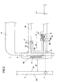
- FIG. 2 shows a variant of the movement generating device 8 in detail.
- this has a (rigidly connected to the receptacle 5) support member 5b, which is biased in the rest position by a tensioned spring 13 against the back frame 12, so that a relaxation movement of the spring 13 to a Displacement of the recording 5 (including carrier 5b) along the direction of movement B to the support structure 2 out.
- a first locking element 15 is provided which is pivotally supported between a first and a second position on the support 5b, the first locking element 15 in the first position in engagement with a recess 14a of the back frame 14, which receives the force with which the spring 13 is biased along the direction of movement B against the carrier 5b.
- a magnetic coil 16 is provided, which is responsive to the first signal of the pre-crash Detection device 7 toward a pin 16a presses against the first Verrieglungselement 15 so that it gets out of engagement with the recess 14a of the back frame 14. So that a controlled displacement of the receptacle 5 in the direction of the support structure 2 is possible, the receptacle 5 is guided longitudinally displaceable along the direction of movement B via the support 5b on the back frame 14.
- the second locking element 17 is formed as a pivotable, pivotally mounted on the carrier 5b lever which is biased when moving the receptacle 5 from the rest position to the operating position against a vehicle transverse axis y extending portion 18 of the back frame 14 and can slide along this ,
- the second locking element 17 engages in recesses 19 provided along the area 18, which are designed so that the second locking element 17 automatically moves out of engagement with such a recess 19 when moving in the direction of the operating position, wherein each the recesses 19 acts as an abutment for the support 5b of the receptacle 5 connected to the second locking element 17 when it is acted upon by a force against the direction of movement B (intruding collision object).
- the second locking element 17 snaps into a recess 19 of the region 18 in the movement of the carrier 5a against the direction of movement B, it can no longer be disengaged from the respective recess 19, unless it is transverse to the direction of movement B. Oriented force pivots the second locking element 17 out of the respective recess 19 out.
- a separate actuator may be provided.
Landscapes
- Engineering & Computer Science (AREA)
- Mechanical Engineering (AREA)
- Aviation & Aerospace Engineering (AREA)
- Transportation (AREA)
- Air Bags (AREA)
- Seats For Vehicles (AREA)
Applications Claiming Priority (2)
| Application Number | Priority Date | Filing Date | Title |
|---|---|---|---|
| DE102005062849A DE102005062849A1 (de) | 2005-12-23 | 2005-12-23 | Insassenrückhalteeinrichtung für ein Kraftfahrzeug |
| PCT/EP2006/012647 WO2007073944A1 (de) | 2005-12-23 | 2006-12-22 | Insassenrückhalteeinrichtung für ein kraftfahrzeug |
Publications (2)
| Publication Number | Publication Date |
|---|---|
| EP1963145A1 EP1963145A1 (de) | 2008-09-03 |
| EP1963145B1 true EP1963145B1 (de) | 2009-04-15 |
Family
ID=37891887
Family Applications (2)
| Application Number | Title | Priority Date | Filing Date |
|---|---|---|---|
| EP06829907A Expired - Fee Related EP1963145B1 (de) | 2005-12-23 | 2006-12-22 | Insassenrückhalteeinrichtung für ein kraftfahrzeug |
| EP06829906A Expired - Fee Related EP1963133B1 (de) | 2005-12-23 | 2006-12-22 | Insassenrückhalteeinrichtung für ein kraftfahrzeug |
Family Applications After (1)
| Application Number | Title | Priority Date | Filing Date |
|---|---|---|---|
| EP06829906A Expired - Fee Related EP1963133B1 (de) | 2005-12-23 | 2006-12-22 | Insassenrückhalteeinrichtung für ein kraftfahrzeug |
Country Status (6)
| Country | Link |
|---|---|
| US (2) | US7946614B2 (enExample) |
| EP (2) | EP1963145B1 (enExample) |
| JP (2) | JP5030968B2 (enExample) |
| CN (2) | CN101346255B (enExample) |
| DE (3) | DE102005062849A1 (enExample) |
| WO (2) | WO2007077035A1 (enExample) |
Families Citing this family (72)
| Publication number | Priority date | Publication date | Assignee | Title |
|---|---|---|---|---|
| DE102005062849A1 (de) * | 2005-12-23 | 2007-09-06 | Takata-Petri Ag | Insassenrückhalteeinrichtung für ein Kraftfahrzeug |
| ATE543693T1 (de) | 2007-03-15 | 2012-02-15 | Takata Petri Ag | Fahrzeugsitzanordnung und verfahren zum schützen eines fahrzeuginsassen |
| DE102007013543A1 (de) * | 2007-03-16 | 2008-09-25 | Takata-Petri Ag | Insassenrückhalteeinrichtung für ein Kraftfahrzeug und Verfahren zum Rückhalten eines Insassen eines Kraftfahrzeuges |
| US7669888B2 (en) * | 2007-07-19 | 2010-03-02 | Toyoda Gosei Co., Ltd. | Side airbag apparatus |
| KR100844426B1 (ko) * | 2007-07-26 | 2008-07-08 | 현대자동차주식회사 | 사이드 에어백이 구비된 시트 |
| DE102007045550A1 (de) * | 2007-09-24 | 2009-04-02 | Autoliv Development Ab | Kraftfahrzeugsitz |
| JP5056375B2 (ja) * | 2007-11-27 | 2012-10-24 | トヨタ自動車株式会社 | 車両用シート |
| DE102008005272A1 (de) | 2008-01-19 | 2009-07-23 | Autoliv Development Ab | Sicherheitseinrichtung für ein Fahrzeug und Verfahren zur Steuerung einer Sicherheitseinrichtung |
| US7695064B2 (en) | 2008-06-24 | 2010-04-13 | Gm Global Technology Operations, Inc. | Vehicle seat side air bag |
| DE102008032981B4 (de) * | 2008-07-07 | 2014-02-13 | TAKATA Aktiengesellschaft | Fahrzeugsitzanordnung |
| RU2463181C1 (ru) | 2008-07-15 | 2012-10-10 | Таката-Петри Аг | Устройство автомобильного сиденья и устройство газового мешка для автомобиля, а также метод защиты пассажира автомобиля |
| DE102008062449B4 (de) | 2008-12-15 | 2010-03-18 | Takata-Petri Ag | Fahrzeugsitz für ein Kraftfahrzeug |
| JP5262843B2 (ja) * | 2009-03-03 | 2013-08-14 | 日産自動車株式会社 | 乗員保護装置 |
| DE102009001426A1 (de) * | 2009-03-10 | 2010-09-16 | Robert Bosch Gmbh | Haltevorrichtung und Verfahren zum Halten eines Fahrzeuginsassen in einem Fahrzeugsitz |
| EP2412567B1 (en) * | 2009-03-24 | 2013-10-16 | Honda Motor Co., Ltd. | Vehicle seat |
| DE102009020154B4 (de) | 2009-05-06 | 2015-11-19 | TAKATA Aktiengesellschaft | Fahrzeugsitze für ein Kraftfahrzeug |
| DE102009021045A1 (de) | 2009-05-13 | 2010-11-18 | Dürschinger, Günter | Insassenschutzeinrichtung für ein Kraftfahrzeug bei einem Seitenaufprall |
| WO2010150449A1 (ja) * | 2009-06-24 | 2010-12-29 | 本田技研工業株式会社 | 車両用シート |
| DE102009047393A1 (de) * | 2009-12-02 | 2011-06-09 | Robert Bosch Gmbh | Haltevorrichtung zum Halten eines Fahrzeuginsassen in einem Fahrzeugsitz sowie Verfahren zum Betätigen der Haltevorrichtung |
| JP5060542B2 (ja) * | 2009-12-15 | 2012-10-31 | 本田技研工業株式会社 | 乗員保護装置 |
| WO2011077510A1 (ja) * | 2009-12-21 | 2011-06-30 | トヨタ自動車株式会社 | サイドエアバッグ装置及びサイドエアバッグの縫製方法 |
| CA2862855C (en) * | 2011-01-31 | 2018-06-12 | Simon Fraser University | Inflation method and apparatus for an airbag |
| JP5961341B2 (ja) * | 2011-02-25 | 2016-08-02 | 富士重工業株式会社 | 乗員保護装置 |
| EP2596995B1 (en) * | 2011-11-22 | 2014-09-17 | Zodiac Seats France | Airbag guided by seat belt |
| JP5664537B2 (ja) * | 2011-12-19 | 2015-02-04 | トヨタ自動車株式会社 | 後席用サイドエアバッグ装置 |
| DE202012102471U1 (de) * | 2012-06-18 | 2012-09-07 | Cybex Gmbh | Kindersitz zur Anbringung auf einem Kraftfahrzeugsitz |
| US9211820B2 (en) | 2012-11-01 | 2015-12-15 | Graco Children's Products Inc. | Child safety seat with side impact energy redirection |
| US9399418B2 (en) | 2013-01-24 | 2016-07-26 | Ford Global Technologies, Llc | Independent cushion extension and thigh support |
| US9415713B2 (en) | 2013-01-24 | 2016-08-16 | Ford Global Technologies, Llc | Flexible seatback system |
| US9409504B2 (en) | 2013-01-24 | 2016-08-09 | Ford Global Technologies, Llc | Flexible seatback system |
| DE102013101540B4 (de) * | 2013-02-15 | 2021-10-07 | Faurecia Autositze Gmbh | Fahrzeugsitz, insbesondere für ein Kraftfahrzeug |
| ES2945860T3 (es) * | 2013-07-16 | 2023-07-10 | Britax Roemer Kindersicherheit Gmbh | Asiento de seguridad para niños |
| DE102013015209B4 (de) * | 2013-09-13 | 2023-06-29 | Autoliv Development Ab | Airbagsystem, Fahrzeugsitz mit einem Airbagsystem und Verfahren zum Aktivieren eines Airbagsystems |
| US20150108744A1 (en) * | 2013-10-17 | 2015-04-23 | Ford Global Technologies,Llc | Integrated side impact and rear occupant front impact protection bolsters |
| DE102013017957A1 (de) * | 2013-10-29 | 2015-04-30 | Daimler Ag | Verfahren zur Ansteuerung zumindest eines in einem Fahrzeugsitz angeordneten Schutzelementes |
| US9315131B2 (en) | 2014-01-23 | 2016-04-19 | Ford Global Technologies, Llc | Suspension seat back and cushion system having an inner suspension panel |
| US9421894B2 (en) | 2014-04-02 | 2016-08-23 | Ford Global Technologies, Llc | Vehicle seating assembly with manual independent thigh supports |
| CA2949071C (en) | 2014-05-13 | 2020-05-12 | Schlage Lock Company Llc | Lock device having position sensor |
| US9789790B2 (en) | 2014-10-03 | 2017-10-17 | Ford Global Technologies, Llc | Tuned flexible support member and flexible suspension features for comfort carriers |
| JP6225877B2 (ja) * | 2014-10-22 | 2017-11-08 | トヨタ自動車株式会社 | 車両用サイドエアバッグ装置 |
| US10046682B2 (en) | 2015-08-03 | 2018-08-14 | Ford Global Technologies, Llc | Back cushion module for a vehicle seating assembly |
| US10286818B2 (en) | 2016-03-16 | 2019-05-14 | Ford Global Technologies, Llc | Dual suspension seating assembly |
| US9849817B2 (en) | 2016-03-16 | 2017-12-26 | Ford Global Technologies, Llc | Composite seat structure |
| US9994135B2 (en) | 2016-03-30 | 2018-06-12 | Ford Global Technologies, Llc | Independent cushion thigh support |
| US10220737B2 (en) | 2016-04-01 | 2019-03-05 | Ford Global Technologies, Llc | Kinematic back panel |
| US9889773B2 (en) | 2016-04-04 | 2018-02-13 | Ford Global Technologies, Llc | Anthropomorphic upper seatback |
| US9802512B1 (en) | 2016-04-12 | 2017-10-31 | Ford Global Technologies, Llc | Torsion spring bushing |
| US9845029B1 (en) | 2016-06-06 | 2017-12-19 | Ford Global Technologies, Llc | Passive conformal seat with hybrid air/liquid cells |
| US9834166B1 (en) | 2016-06-07 | 2017-12-05 | Ford Global Technologies, Llc | Side airbag energy management system |
| US9849856B1 (en) | 2016-06-07 | 2017-12-26 | Ford Global Technologies, Llc | Side airbag energy management system |
| US10377279B2 (en) | 2016-06-09 | 2019-08-13 | Ford Global Technologies, Llc | Integrated decking arm support feature |
| US10166895B2 (en) | 2016-06-09 | 2019-01-01 | Ford Global Technologies, Llc | Seatback comfort carrier |
| US10286824B2 (en) | 2016-08-24 | 2019-05-14 | Ford Global Technologies, Llc | Spreader plate load distribution |
| US10279714B2 (en) | 2016-08-26 | 2019-05-07 | Ford Global Technologies, Llc | Seating assembly with climate control features |
| US10239431B2 (en) | 2016-09-02 | 2019-03-26 | Ford Global Technologies, Llc | Cross-tube attachment hook features for modular assembly and support |
| US10391910B2 (en) | 2016-09-02 | 2019-08-27 | Ford Global Technologies, Llc | Modular assembly cross-tube attachment tab designs and functions |
| US9914378B1 (en) | 2016-12-16 | 2018-03-13 | Ford Global Technologies, Llc | Decorative and functional upper seatback closeout assembly |
| US10596936B2 (en) | 2017-05-04 | 2020-03-24 | Ford Global Technologies, Llc | Self-retaining elastic strap for vent blower attachment to a back carrier |
| KR102409213B1 (ko) * | 2018-01-11 | 2022-06-15 | 아우토리브 디벨롭먼트 아베 | 승차인 보호 장치 |
| DE102018101706A1 (de) * | 2018-01-25 | 2019-07-25 | Faurecia Autositze Gmbh | Fahrzeugsitz |
| CN108674265B (zh) * | 2018-07-12 | 2024-02-27 | 浙江博安母婴用品有限公司 | 一种儿童安全座椅的可伸缩侧保护气囊 |
| US10632955B2 (en) * | 2018-09-25 | 2020-04-28 | Honda Motor Co., Ltd. | Deployable seat mounted occupant shoulder restraint for side impact |
| CN111376864B (zh) * | 2018-12-11 | 2022-02-01 | 上海汽车集团股份有限公司 | 一种侧碰安全装置、控制系统及汽车 |
| US11007971B2 (en) | 2019-02-15 | 2021-05-18 | Ford Global Technologies, Llc | Side airbag including spacer chamber |
| DE102019116586A1 (de) * | 2019-06-19 | 2020-12-24 | Zf Automotive Germany Gmbh | Gassackmodul, Fahrzeugsitz mit Gassackmodul und Fahrzeug |
| KR102656154B1 (ko) * | 2019-08-21 | 2024-04-11 | 아우토리브 디벨롭먼트 아베 | 에어백 장치 |
| JP7340402B2 (ja) | 2019-10-01 | 2023-09-07 | 株式会社ダイセル | 乗員保護システム |
| CN110843714B (zh) * | 2019-11-15 | 2020-11-24 | 江苏理工学院 | 一种延时引爆汽车安全气囊及其控制方法 |
| DE102019130849A1 (de) * | 2019-11-15 | 2021-05-20 | Faurecia Autositze Gmbh | Airbag-Baugruppe, Strukturelement und Airbag-Einheit |
| US11511656B2 (en) * | 2021-03-24 | 2022-11-29 | Monahan Products, LLC | Child restraint system with side impact bumper |
| US11827172B1 (en) * | 2022-09-12 | 2023-11-28 | GM Global Technology Operations LLC | Under thigh side impact airbag (UT-SIAB) for a vehicle |
| JP2024068530A (ja) * | 2022-11-08 | 2024-05-20 | 株式会社Subaru | 車両の乗員保護装置 |
Family Cites Families (33)
| Publication number | Priority date | Publication date | Assignee | Title |
|---|---|---|---|---|
| DE4024838C2 (de) | 1990-08-04 | 1996-05-23 | Audi Ag | Sitz für Fahrzeuge |
| US5505487A (en) * | 1995-05-15 | 1996-04-09 | Trw Vehicle Safety Systems, Inc. | Side impact head air bag module |
| JPH0939628A (ja) * | 1995-08-01 | 1997-02-10 | Mitsubishi Motors Corp | 乗員保護装置 |
| EP0782944B1 (en) * | 1995-08-02 | 1999-03-10 | Toyo Tire & Rubber Co., Ltd . | Side air bag device |
| JP3120726B2 (ja) * | 1995-12-14 | 2000-12-25 | トヨタ自動車株式会社 | 側突用エアバッグを備えたシート構造 |
| US5944341A (en) * | 1996-05-31 | 1999-08-31 | Nissan Motor Co., Ltd. | Air bag apparatus for vehicle |
| JP3385853B2 (ja) * | 1996-05-31 | 2003-03-10 | 日産自動車株式会社 | 車両用エアバッグ装置 |
| WO1997045297A1 (en) * | 1996-05-31 | 1997-12-04 | Nissan Motor Co., Ltd. | Air bag apparatus for seat of vehicle |
| JP3330032B2 (ja) * | 1996-10-25 | 2002-09-30 | 本田技研工業株式会社 | エアバッグ装置 |
| DE19746387B4 (de) * | 1996-10-25 | 2004-06-24 | Honda Giken Kogyo K.K. | Airbagvorrichtung |
| DE19748026A1 (de) | 1997-10-30 | 1999-05-12 | Takata Europ Gmbh | Sicherheitsvorrichtung für ein Kraftfahrzeug |
| US6450528B1 (en) * | 1998-10-01 | 2002-09-17 | Toyota Jidosha Kabushiki Kaisha | Vehicle seat housing an airbag device |
| US6203105B1 (en) * | 1999-08-20 | 2001-03-20 | Mccord Winn Textron Inc. | Vehicle impact responsive multiple bladder seating and headrest system and method |
| DE19950702B4 (de) | 1999-10-21 | 2009-12-24 | Volkswagen Ag | Kraftfahrzeugsitz |
| DE10043290C1 (de) * | 2000-09-02 | 2002-04-18 | Acts Gmbh & Co Kg | Vorrichtung zum Schutz der Insassen eines Fahrzeuges bei einem Aufprall des Fahrzeuges auf ein Hindernis |
| DE10056961A1 (de) * | 2000-11-17 | 2002-06-27 | Lear Corp Gmbh & Co Kg | Aufprallschutzvorrichtung |
| DE10057151A1 (de) * | 2000-11-17 | 2001-06-28 | Audi Ag | Seitenaufprallschutzvorrichtung und Seitenaufprallschutzverfahren |
| DE10137634A1 (de) * | 2001-08-03 | 2003-02-20 | Daimler Chrysler Ag | Sicherheitseinrichtung für einen Kraftwagensitz |
| FR2830814B1 (fr) * | 2001-10-11 | 2004-01-30 | Peugeot Citroen Automobiles Sa | Siege de vehicule automobile equipe d'un dispositif de securite a sac gonflable |
| DE10316543A1 (de) * | 2002-04-11 | 2003-11-13 | Toyoda Gosei Kk | Luftsackvorrichtung |
| JP3994781B2 (ja) * | 2002-04-11 | 2007-10-24 | 豊田合成株式会社 | エアバッグ装置 |
| JP3972736B2 (ja) * | 2002-06-04 | 2007-09-05 | タカタ株式会社 | 乗員保護装置 |
| GB2397048A (en) * | 2003-01-10 | 2004-07-14 | Autoliv Dev | Vehicle seat comprising airbag |
| GB2408239A (en) * | 2003-11-19 | 2005-05-25 | Autoliv Dev | Safety arrangement actuated to restrain forward movement of a vehicle occupant's knees |
| US7134685B2 (en) * | 2004-01-16 | 2006-11-14 | Lear Corporation | Air bag deployment arrangement |
| US20050156411A1 (en) * | 2004-01-20 | 2005-07-21 | Trw Vehicle Safety Systems Inc. | Method and apparatus for helping to protect an occupant of a vehicle |
| EP1559622B1 (en) * | 2004-01-27 | 2013-05-22 | Takata Corporation | Vehicle passenger protecting apparatus |
| US20050218632A1 (en) * | 2004-03-31 | 2005-10-06 | Jess Cuevas | Restorable vehicle occupant safety system |
| DE102004020643A1 (de) * | 2004-04-22 | 2005-11-17 | Takata-Petri (Ulm) Gmbh | Sicherheitsvorrichtung |
| DE102005001597B4 (de) | 2005-01-12 | 2008-02-14 | Autoliv Development Ab | Sicherheitssystem |
| DE102005002464B4 (de) * | 2005-01-18 | 2009-04-02 | Autoliv Development Ab | Sicherheitsanordnung |
| DE102005059197B4 (de) * | 2005-12-06 | 2008-04-10 | Takata-Petri Ag | Fahrzeuginsassen-Rückhaltesysteme mit einem in einem Fahrzeugsitz angeordneten aufblasbaren Gassack |
| DE102005062849A1 (de) * | 2005-12-23 | 2007-09-06 | Takata-Petri Ag | Insassenrückhalteeinrichtung für ein Kraftfahrzeug |
-
2005
- 2005-12-23 DE DE102005062849A patent/DE102005062849A1/de not_active Withdrawn
-
2006
- 2006-12-22 EP EP06829907A patent/EP1963145B1/de not_active Expired - Fee Related
- 2006-12-22 DE DE502006003503T patent/DE502006003503D1/de active Active
- 2006-12-22 CN CN2006800487232A patent/CN101346255B/zh not_active Expired - Fee Related
- 2006-12-22 JP JP2008546295A patent/JP5030968B2/ja not_active Expired - Fee Related
- 2006-12-22 EP EP06829906A patent/EP1963133B1/de not_active Expired - Fee Related
- 2006-12-22 JP JP2008546296A patent/JP5030969B2/ja not_active Expired - Fee Related
- 2006-12-22 DE DE502006003690T patent/DE502006003690D1/de active Active
- 2006-12-22 WO PCT/EP2006/012645 patent/WO2007077035A1/de not_active Ceased
- 2006-12-22 CN CN2006800487726A patent/CN101346262B/zh not_active Expired - Fee Related
- 2006-12-22 WO PCT/EP2006/012647 patent/WO2007073944A1/de not_active Ceased
-
2008
- 2008-06-19 US US12/213,480 patent/US7946614B2/en not_active Expired - Fee Related
- 2008-06-19 US US12/213,479 patent/US7775552B2/en not_active Expired - Fee Related
Also Published As
| Publication number | Publication date |
|---|---|
| WO2007077035A1 (de) | 2007-07-12 |
| DE502006003690D1 (de) | 2009-06-18 |
| CN101346262A (zh) | 2009-01-14 |
| JP5030968B2 (ja) | 2012-09-19 |
| JP2009520627A (ja) | 2009-05-28 |
| US7946614B2 (en) | 2011-05-24 |
| EP1963133A1 (de) | 2008-09-03 |
| DE102005062849A1 (de) | 2007-09-06 |
| CN101346262B (zh) | 2011-02-16 |
| JP2009520628A (ja) | 2009-05-28 |
| US20090008914A1 (en) | 2009-01-08 |
| CN101346255A (zh) | 2009-01-14 |
| EP1963133B1 (de) | 2009-05-06 |
| DE502006003503D1 (de) | 2009-05-28 |
| CN101346255B (zh) | 2011-06-29 |
| US7775552B2 (en) | 2010-08-17 |
| JP5030969B2 (ja) | 2012-09-19 |
| US20090008913A1 (en) | 2009-01-08 |
| WO2007073944A1 (de) | 2007-07-05 |
| EP1963145A1 (de) | 2008-09-03 |
Similar Documents
| Publication | Publication Date | Title |
|---|---|---|
| EP1963145B1 (de) | Insassenrückhalteeinrichtung für ein kraftfahrzeug | |
| DE102017103063B4 (de) | Insassenschutzvorrichtung | |
| EP1199227B1 (de) | Baugruppe bestehend aus Sitzlehne und Gassack-Modul | |
| EP1159163B1 (de) | Sicherheitsvorrichtung mit einer airbaganordnung aus mehreren airbags für ein kraftfahrzeug | |
| DE10066268B4 (de) | Sicherheitssystem für ein Kraftfahrzeug | |
| EP2310234B1 (de) | Fahrzeugsitzanordnung und gassackanordnung für ein kraftfahrzeug sowie verfahren zum schützen eines fahrzeuginsassen | |
| DE29615485U1 (de) | Rückhaltesystem für Fahrzeuginsassen | |
| DE102020102180A1 (de) | Entfaltbare platte für einen airbag | |
| DE3908713A1 (de) | Gassack-kniepolster-rueckhaltesystem fuer kraftfahrzeuge | |
| DE102016122027A1 (de) | Vorrichtung, System und Verfahren für ein aufprallaktiviertes Schnappschloss für Handschuhfachdeckel | |
| DE102006042036A1 (de) | Fahrzeuginsassenschutzvorrichtung und Inbetriebnahmeverfahren derselben | |
| DE102008048726A1 (de) | Knieschutzairbagvorrichtung | |
| DE102013216900A1 (de) | Anordnungsstruktur für ein Vorhang-Airbagsystem | |
| DE102020126149A1 (de) | Auslösbare platte für einen airbag | |
| DE60009201T2 (de) | Aufblasbares Kraftfahrzeugrückhaltesystem mit Modul zum Entfalten einer Verkleidungskomponente | |
| DE10021845A1 (de) | Dualairbagsystem als Rückhaltemittel bei einem Frontalaufprall | |
| DE10063473A1 (de) | Dachholm-Verkleidung für aufblasbares Rückhaltesystem | |
| DE19905784A1 (de) | Kraftfahrzeug mit einer Aufprallschutzvorrichtung | |
| DE10316542B4 (de) | Luftsackvorrichtung für ein Fahrzeug und Verfahren zum Entfalten eines Luftsacks | |
| DE10039802B4 (de) | Sicherheitseinrichtung für die Insassen eines Fahrzeugs, insbesondere eines Kraftfahrzeugs | |
| DE102005002466B4 (de) | Sicherheitssystem | |
| DE102023124489A1 (de) | Über eine türöffnung aufblasbarer kabelgestützter airbag | |
| DE10111597B4 (de) | Insassenschutzvorrichtung für ein Fahrzeug, insbesondere für ein Kraftfahrzeug | |
| DE10057941A1 (de) | Energieabsorbierende Fronthaube an einem Fahrzeug | |
| DE19915974B4 (de) | Insassenschutzvorrichtung mit einem Airbag für ein Kraftfahrzeug |
Legal Events
| Date | Code | Title | Description |
|---|---|---|---|
| PUAI | Public reference made under article 153(3) epc to a published international application that has entered the european phase |
Free format text: ORIGINAL CODE: 0009012 |
|
| 17P | Request for examination filed |
Effective date: 20080328 |
|
| AK | Designated contracting states |
Kind code of ref document: A1 Designated state(s): DE FR |
|
| RIN1 | Information on inventor provided before grant (corrected) |
Inventor name: KLIMA, JOSEF Inventor name: BREUNINGER, MARTIN |
|
| GRAP | Despatch of communication of intention to grant a patent |
Free format text: ORIGINAL CODE: EPIDOSNIGR1 |
|
| RBV | Designated contracting states (corrected) |
Designated state(s): DE FR |
|
| GRAS | Grant fee paid |
Free format text: ORIGINAL CODE: EPIDOSNIGR3 |
|
| GRAA | (expected) grant |
Free format text: ORIGINAL CODE: 0009210 |
|
| AK | Designated contracting states |
Kind code of ref document: B1 Designated state(s): DE FR |
|
| REF | Corresponds to: |
Ref document number: 502006003503 Country of ref document: DE Date of ref document: 20090528 Kind code of ref document: P |
|
| PLBE | No opposition filed within time limit |
Free format text: ORIGINAL CODE: 0009261 |
|
| STAA | Information on the status of an ep patent application or granted ep patent |
Free format text: STATUS: NO OPPOSITION FILED WITHIN TIME LIMIT |
|
| 26N | No opposition filed |
Effective date: 20100118 |
|
| PGFP | Annual fee paid to national office [announced via postgrant information from national office to epo] |
Ref country code: FR Payment date: 20111219 Year of fee payment: 6 |
|
| REG | Reference to a national code |
Ref country code: DE Ref legal event code: R082 Ref document number: 502006003503 Country of ref document: DE Representative=s name: MAIKOWSKI & NINNEMANN PATENTANWAELTE, DE |
|
| REG | Reference to a national code |
Ref country code: DE Ref legal event code: R082 Ref document number: 502006003503 Country of ref document: DE Representative=s name: MAIKOWSKI & NINNEMANN PATENTANWAELTE, DE Effective date: 20120904 Ref country code: DE Ref legal event code: R081 Ref document number: 502006003503 Country of ref document: DE Owner name: TAKATA AKTIENGESELLSCHAFT, DE Free format text: FORMER OWNER: TAKATA-PETRI AG, 63743 ASCHAFFENBURG, DE Effective date: 20120904 Ref country code: DE Ref legal event code: R082 Ref document number: 502006003503 Country of ref document: DE Representative=s name: MAIKOWSKI & NINNEMANN PATENTANWAELTE PARTNERSC, DE Effective date: 20120904 Ref country code: DE Ref legal event code: R081 Ref document number: 502006003503 Country of ref document: DE Owner name: JOYSON SAFETY SYSTEMS GERMANY GMBH, DE Free format text: FORMER OWNER: TAKATA-PETRI AG, 63743 ASCHAFFENBURG, DE Effective date: 20120904 |
|
| REG | Reference to a national code |
Ref country code: FR Ref legal event code: ST Effective date: 20130830 |
|
| PG25 | Lapsed in a contracting state [announced via postgrant information from national office to epo] |
Ref country code: FR Free format text: LAPSE BECAUSE OF NON-PAYMENT OF DUE FEES Effective date: 20130102 |
|
| REG | Reference to a national code |
Ref country code: DE Ref legal event code: R082 Ref document number: 502006003503 Country of ref document: DE Representative=s name: MAIKOWSKI & NINNEMANN PATENTANWAELTE PARTNERSC, DE Ref country code: DE Ref legal event code: R081 Ref document number: 502006003503 Country of ref document: DE Owner name: JOYSON SAFETY SYSTEMS GERMANY GMBH, DE Free format text: FORMER OWNER: TAKATA AKTIENGESELLSCHAFT, 63743 ASCHAFFENBURG, DE |
|
| PGFP | Annual fee paid to national office [announced via postgrant information from national office to epo] |
Ref country code: DE Payment date: 20200227 Year of fee payment: 14 |
|
| REG | Reference to a national code |
Ref country code: DE Ref legal event code: R119 Ref document number: 502006003503 Country of ref document: DE |
|
| PG25 | Lapsed in a contracting state [announced via postgrant information from national office to epo] |
Ref country code: DE Free format text: LAPSE BECAUSE OF NON-PAYMENT OF DUE FEES Effective date: 20210701 |