EP1961868A2 - Montagestruktur eines Filters für eine Kühleinheit einer Baumaschine - Google Patents
Montagestruktur eines Filters für eine Kühleinheit einer Baumaschine Download PDFInfo
- Publication number
- EP1961868A2 EP1961868A2 EP08151727A EP08151727A EP1961868A2 EP 1961868 A2 EP1961868 A2 EP 1961868A2 EP 08151727 A EP08151727 A EP 08151727A EP 08151727 A EP08151727 A EP 08151727A EP 1961868 A2 EP1961868 A2 EP 1961868A2
- Authority
- EP
- European Patent Office
- Prior art keywords
- filter
- cooler
- mounting portion
- elastic body
- force
- Prior art date
- Legal status (The legal status is an assumption and is not a legal conclusion. Google has not performed a legal analysis and makes no representation as to the accuracy of the status listed.)
- Granted
Links
Images


Classifications
-
- E—FIXED CONSTRUCTIONS
- E02—HYDRAULIC ENGINEERING; FOUNDATIONS; SOIL SHIFTING
- E02F—DREDGING; SOIL-SHIFTING
- E02F9/00—Component parts of dredgers or soil-shifting machines, not restricted to one of the kinds covered by groups E02F3/00 - E02F7/00
-
- E—FIXED CONSTRUCTIONS
- E02—HYDRAULIC ENGINEERING; FOUNDATIONS; SOIL SHIFTING
- E02F—DREDGING; SOIL-SHIFTING
- E02F9/00—Component parts of dredgers or soil-shifting machines, not restricted to one of the kinds covered by groups E02F3/00 - E02F7/00
- E02F9/08—Superstructures; Supports for superstructures
- E02F9/0858—Arrangement of component parts installed on superstructures not otherwise provided for, e.g. electric components, fenders, air-conditioning units
- E02F9/0866—Engine compartment, e.g. heat exchangers, exhaust filters, cooling devices, silencers, mufflers, position of hydraulic pumps in the engine compartment
-
- B—PERFORMING OPERATIONS; TRANSPORTING
- B60—VEHICLES IN GENERAL
- B60K—ARRANGEMENT OR MOUNTING OF PROPULSION UNITS OR OF TRANSMISSIONS IN VEHICLES; ARRANGEMENT OR MOUNTING OF PLURAL DIVERSE PRIME-MOVERS IN VEHICLES; AUXILIARY DRIVES FOR VEHICLES; INSTRUMENTATION OR DASHBOARDS FOR VEHICLES; ARRANGEMENTS IN CONNECTION WITH COOLING, AIR INTAKE, GAS EXHAUST OR FUEL SUPPLY OF PROPULSION UNITS IN VEHICLES
- B60K11/00—Arrangement in connection with cooling of propulsion units
- B60K11/02—Arrangement in connection with cooling of propulsion units with liquid cooling
-
- B—PERFORMING OPERATIONS; TRANSPORTING
- B60—VEHICLES IN GENERAL
- B60Y—INDEXING SCHEME RELATING TO ASPECTS CROSS-CUTTING VEHICLE TECHNOLOGY
- B60Y2200/00—Type of vehicle
- B60Y2200/40—Special vehicles
- B60Y2200/41—Construction vehicles, e.g. graders, excavators
-
- F—MECHANICAL ENGINEERING; LIGHTING; HEATING; WEAPONS; BLASTING
- F01—MACHINES OR ENGINES IN GENERAL; ENGINE PLANTS IN GENERAL; STEAM ENGINES
- F01P—COOLING OF MACHINES OR ENGINES IN GENERAL; COOLING OF INTERNAL-COMBUSTION ENGINES
- F01P11/00—Component parts, details, or accessories not provided for in, or of interest apart from, groups F01P1/00 - F01P9/00
- F01P11/12—Filtering, cooling, or silencing cooling-air
Definitions
- the present invention relates to a mounting structure of filter for cooler of construction machine detachably mounted on the front surface side of the cooler such as radiator.
- a working attachment (not shown) is mounted in a front section of an upper rotating body 2 disposed rotatably around a vertical shaft on a crawler type lower traveling body 1 shown in Figs. 8 and 9 .
- an engine 4 is installed in the left and right direction (width direction) of the upper rotating body 2 in an engine room 3 in a rear section of the upper rotating body 2.
- a hydraulic pump 5 driven by the engine 4, and on the left side thereof, is provided a cooler 6.
- the cooler 6 is formed of a plurality of heat exchangers such as a radiator for cooling the engine, an oil cooler for cooling working oil and an intercooler for a turbocharger.
- the cooler 6 is shown as a single unit.
- a cooling fan 7 By rotation of a cooling fan 7 provided between the cooler 6 and the engine 4, the outside air is sucked in from a suction opening (not shown) in an external body (usually called as a guard) for forming the engine room 3 and passes through the cooler 6 as the cooling air.
- the upper surface side of the external body is formed of a hood 8 (refer to Fig. 8 ) provided with a bonnet, and a back surface and a side surface thereof are formed of a counterweight 9.
- Maintenance ports 10 and 11 from the exterior on both the left and right sides of the counterweight 9 are opened and closed by maintenance panels 12 and 13. It should be noted that hinges 14 are centers for opening and closing the panels 12 and 13.
- a filter 16 To a tip of a duct 15 for bringing the sucked air to the cooler 6 on the front surface side of the cooler 6 (the side of a surface opposing to a flow of the sucked air, that is, a surface on the left side of the upper rotating body 2), is detachably mounted a filter 16.
- a portion of mounting the filter is enlarged and shown in Figs. 10 and 11 .
- the filter 16 is divided into two as in Fig. 11 , and both upper and lower filters 17 and 18 are mounted to the tip of the duct in a state of being in contact with each other on the upper and lower sides respectively.
- a filter mounting portion 19 provided with a filter abutment surface 19a facing towards the upstream side of the air flow.
- a peripheral edge part of the filter 16 is fitted into the mounting portion 19 in a state of being brought into abutment with the abutment surface 19a.
- an upper end part and both front and rear end parts of the upper filter 17 are mounted to the filter mounting portion 19, and a lower end part and both front and rear end parts of the lower filter 18 are mounted to the filter mounting portion 19.
- a filter frame is mounted to a circumference of a filter main body.
- the filter 16 is directly mounted on the front surface side of the cooler 6 without the duct 15.
- the filter 16 is formed as a single filter.
- the filter 16 Since maintenance is highly frequently required for the filter 16, the filter 16 is detachably mounted to the filter mounting portion 19.
- a fastening tool such as a butterfly bolt and a pin is used for the peripheral edge part of the filter 16 (an upper part and both the front and rear sides of the upper filter 17 and a lower part and both the front and rear sides of the lower filter 18).
- attachment and detachment of the filter 16 are more desirably performed through the left maintenance port 10 from the ground by opening the left maintenance panel 12 as in Fig. 9 than performed from the upper surface side of the engine room by getting on the hood 8 in terms of operating efficiency and safety
- the present invention is a mounting structure of filter for cooler of construction machine detachably mounted on the front surface side of the cooler installed in an engine room of an upper rotating body disposed on a lower traveling body, provided with a configuration that a filter mounting portion provided with a filter abutment surface with which the filter is brought into abutment from the front side of the filter mounting portion is provided on the front surface side of the cooler, an external body for forming the engine room is provided with a maintenance port into or from which the filter is inserted or taken out, and an elastic body for exerting an elastic force in the direction of fixing a position of the filter inserted from the filter maintenance port to the filter mounting portion in a state that the filter is pressed onto the filter abutment surface is provided.
- the filter is pressed onto the filter abutment surface and a position thereof is fixed. Therefore, in comparison to a conventional mounting structure of using a fastening tool such as a butterfly bolt, there is no need for a troublesome fastening operation and position fixing, and the fastening tool is not lost.
- the present invention is a configuration that the elastic force works as a pressing force and a position fixing force for the filter, and there is no part which is directly fastened by hand unlike a conventional fastening tool method. Therefore, there is no need for accessing to the inner side which is not easily touched.
- the pressing force and the position fixing force by the elastic body for the filter are preferably exerted on the front end side of the filter in the present invention provided with the following configuration.
- the filter is provided in the front and rear direction of the upper rotating body, while the elastic body is provided in a state of exerting a pressing force of pressing the filter onto the filter abutment surface on the front end side of the filter and a position fixing force of pushing the filter rearwards.
- an engaging claw is provided in one of a rear end part of the filter and the filter mounting portion, an engaging hole is provided in the other, and the position fixing force of the elastic body works as a force in the direction of engaging the engaging claw with the engaging hole.
- a counterweight also serving as a part of the external body is provided in a rear end part of the upper rotating body, a maintenance port is provided in the counterweight, and cutouts for accepting passage of the filter at the time of inserting or taking out the filter are provided in opening edge parts on both the upper and lower sides of the maintenance port.
- the filter is provided in the front and rear direction of the upper rotating body, and the elastic body is provided in a state of exerting a pressing force of pressing the filter onto the filter abutment surface on the one end side in the up and down direction of the filter, and a position fixing force in the up and down direction.
- the pressing force and the position fixing force by the elastic body for the filter are exerted on the one end side in the up and down direction of the filter.
- a duct for bringing the air taken from the exterior to the cooler is provided on the front surface side of the cooler, and the filter mounting portion is provided in a tip of the duct.
- the filter is pressed and the position thereof is fixed onto the filter mounting portion of the duct.
- the filter is divided into an upper filter and a lower filter on the upper and lower sides respectively, and elastic bodies are provided in both the filters respectively.
- both the filters are pressed and positions thereof are fixed.
- the engaging claw is provided in one of the rear end part of the filter and the filter mounting portion, the engaging hole is provided in the other, and the position fixing force of the elastic body works as the force in the direction of engaging the engaging claw with the engaging hole, the position fixing force of the elastic body works as the force in the direction of engaging the engaging claw with the engaging hole. Therefore, it is possible to ensure a more stable filter fixing effect.
- the maintenance port is provided in the counterweight, the maintenance port is desirably minimized for an original function of counter balance, while space for inserting or taking out the filter is required to be ensured.
- the counterweight also serving as a part of the external body is provided in the rear end part of the upper rotating body
- the maintenance port is provided in the counterweight
- the cutouts for accepting the passage of the filter at the time of inserting or taking out the filter are provided in the opening edge parts on both the upper and lower sides of the maintenance port, the cutouts for accepting the passage of the filter are provided in the opening edge parts on both the upper and lower sides of the maintenance port in the counterweight. Therefore, it is possible to respond the two requirements mentioned above at the same time.
- cutouts serve as guides for inserting or taking out the filter, the filter attachment and detachment work is more easily performed.
- an end part of the filter in the up and down direction is an end part on the inner side.
- the filter is provided in the front and rear direction of the upper rotating body, and the elastic body is provided in a state of exerting the pressing force of pressing the filter onto the filter abutment surface on the one end side in the up and down direction of the filter, and the position fixing force in the up and down direction, the pressing force and the position fixing force by the elastic body for the filter are exerted in the up and down direction. Therefore, even in the above situation, it is possible to easily perform the filter attachment and detachment work.
- a hydraulic excavator is an object to which the present invention is applied.
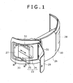
- An example thereof is a case where as shown in Figs. 2 and 3 , a duct 21 is provided in a front surface of a cooler 6 installed in an engine room 3, and a filter 23 is mounted to a filter mounting portion 22 provided in a peripheral edge part of a tip of the duct 21.
- the filter 23 has a structure in which the filter 23 is divided into an upper filter 24 and a lower filter 25 on the upper and lower sides as well as the filter 16 in the related art. Both the filters 24 and 25 are mounted to the filter mounting portion 22 in a state of being in contact with each other in the up and down direction.
- a counterweight 26 also serving as a part of an external body for forming the engine room, are provided left and right maintenance ports 27 and 28, and maintenance panels 29 and 30 for opening and closing the maintenance ports (in Fig. 1 , the reference numeral 31 denotes hinges serving as opening and closing supporting points of the left maintenance panel 29).
- the filter 23 is inserted or taken out through the left maintenance port 27 among the ports.
- cutouts 32 and 33 are provided in opening edge parts on both the upper and lower sides of the left maintenance port 27 in the counterweight 26.
- the upper cutout 32 is formed so as to have width for accepting passage of an upper end part of the upper filter 24, and the lower cutout 33 is formed so as to have width for accepting passage of a lower end part of the lower filter 25.
- the cutouts 32 and 33 position both the filters 24 and 25 towards mounting positions at the time of mounting the filter, and also have a function as guides for determining the direction. That is, only by matching the upper end part of the upper filter 24 and the lower end part of the lower filter 25 with the cutouts 32 and 33, it is possible to determine the positions and the inserting direction of both the filters 24 and 25. Then, by pushing in along the cutouts 32 and 33, the front end side of the filter which is the inner side seen from an operator is led to the front end side of the filter mounting portion 22.
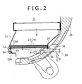
- a filter abutment surface 22a facing towards the upstream side of the air flow around the entire periphery, and an elastic body mounting portion 22b on the front end side which is the inner side seen from the left maintenance port 27.
- an elastic body 34 formed of a plate spring.
- the elastic body 34 As shown in Fig. 4 in detail, for each of both the filters 24 and 25, a base end part thereof is mounted to the elastic body mounting portion 22b in a state that a tip thereof opposes to the filter abutment surface 22a. At the time of inserting the filter, the elastic body 34 is pushed in to the front side by an elastic body protector (elastic body protecting member) 35 provided in a front end part thereof.
- an elastic body protector elastic body protecting member
- the elastic body 34 is inclined so as to generate a restoring force (elastic force) F.
- a force (pressing force) F1 for pressing the filters 24 and 25 onto the filter abutment surface 22a and a force (position fixing force) F2 for pushing the filters 24 and 25 rearwards work on the front end side of the filter.
- an engaging claw 36 protruding in a downwardly-turned shape is provided in the filters 24 and 25, and an engaging hole 37 is provided in the filter mounting portion 22.
- the engaging claw 36 is automatically and elastically engaged with the engaging hole 37.
- the elastic body 34 and the engaging claw 36 and the engaging hole 37 may be provided at an intermediate position in the up and down direction of the filters 24 and 25, or may be provided on the upper end side or the lower end side.
- both the filters 24 and 25 are mounted to the filter mounting portion 22 in a state of closely adhering to the filter abutment surface 22a.
- the present structure it is possible to press the filters 24 and 25 onto the filter abutment surface 22a and fix the positions thereof by the elastic body 34. Therefore, in comparison to a conventional mounting structure of using a fastening tool such as a butterfly bolt, there is no need for a troublesome fastening operation and position fixing, and the fastening tool is not lost.
- the cutouts 32 and 33 for accepting the passage of the filters 24 and 25 are provided in the opening edge parts on both the upper and lower sides of the left maintenance port 27 in the counterweight 26. Therefore, it is possible to insert and take out the filters 24 and 25 with maintaining a vertical posture thereof, and it is also possible to suppress a weight loss of the counterweight 26 to a minimum which is only weight of the cutouts 32 and 33.
- cutouts 32 and 33 serve as the guides for inserting and taking out the filter as above described, the filter attachment and detachment work is more easily performed.
- the engaging claw 36 and the engaging hole 37 are provided on the upper end side of the upper filter 24 and the lower end side of the lower filter 25, it is possible to easily perform a removing operation of the engaging claw 36 from the engaging hole 37 by the upper and lower cutouts 32 and 33.
- the elastic body 34 is provided on the filter mounting portion 22 side, and the elastic body protector 35 is provided on the filters 24 and 25 side. While, in a second embodiment shown in Fig. 5 , the elastic body protector 35 is conversely provided on the filter mounting portion 22 side, and the elastic body (plate spring in a substantially V shape seen from the top) 34 is provided on the filters 24 and 25 side.
- a point that the restoring force (elastic force) F works due to contact between the elastic body 34 and the elastic body protector 35, and as the component force thereof, the pressing force F1 and the position fixing force F2 work is the same as the first embodiment.
- a coil spring is used instead of the plate spring.
- the above elastic body 34 is mounted to the filter mounting portion 22 through an elastic body receiver 38, and the restoring force F of the elastic body 34 and the component force thereof (pressing force F1 and the position fixing force F2) are generated by bringing the elastic body protector 35 into contact with the elastic body receiver 38.
- the above configuration can be applied to a case where the elastic body 34 is provided on the filters 24 and 25 side, and the elastic body protector 35 is provided on the filter mounting portion 22 side as in the second embodiment.
- the restoring force F of the elastic body 34 works on the front end side of the filters 24 and 25. While, in a fourth embodiment shown in Fig. 7 , the elastic bodies 34 are provided in an upper edge part and a lower edge part of the filter mounting portion 22, and the restoring forces F thereof work in the up and down direction on the upper end side of the upper filter 24 and the lower end side of the lower filter 25.
- the working direction of the pressing force F1 serving as the component force is the same as the first to third embodiments.
- the position fixing force F2 works downwards on the upper filter 24 and upwards on the lower filter 25.
- both the filters 24 and 25 are closely adhered to each other on end surfaces which are in contact with each other in the up and down direction so that positions thereof are mutually fixed.
- a horizontal dividing member may be provided in a central part in the up and down direction of the filter mounting portion 22, and both the filters 24 and 25 may be closely adhered to the dividing member by the position fixing force F2.
- the engaging claw 36 and the engaging hole 37 used in the first to third embodiments may be provided.
- the configuration of the fourth embodiment is particularly effective under a situation that the filters 24 and 25 are inserted and taken out from the front surface side of the cooler, and further size of the maintenance port in the up and down direction is small for the filters 24 and 25.
- a filter mounting portion provided with a filter abutment surface with which a filter is brought into abutment from the front side of the filter mounting portion is provided.
- the front end side of the filter pushed in from a maintenance port is pressed onto an elastic body formed of a plate spring and provided in the filter mounting portion.
Landscapes
- Engineering & Computer Science (AREA)
- Mining & Mineral Resources (AREA)
- Civil Engineering (AREA)
- General Engineering & Computer Science (AREA)
- Structural Engineering (AREA)
- Component Parts Of Construction Machinery (AREA)
- Cooling, Air Intake And Gas Exhaust, And Fuel Tank Arrangements In Propulsion Units (AREA)
Applications Claiming Priority (1)
| Application Number | Priority Date | Filing Date | Title |
|---|---|---|---|
| JP2007044098A JP4501945B2 (ja) | 2007-02-23 | 2007-02-23 | 建設機械の冷却器用フィルタの取付構造 |
Publications (3)
| Publication Number | Publication Date |
|---|---|
| EP1961868A2 true EP1961868A2 (de) | 2008-08-27 |
| EP1961868A3 EP1961868A3 (de) | 2010-03-24 |
| EP1961868B1 EP1961868B1 (de) | 2020-06-10 |
Family
ID=39301154
Family Applications (1)
| Application Number | Title | Priority Date | Filing Date |
|---|---|---|---|
| EP08151727.8A Not-in-force EP1961868B1 (de) | 2007-02-23 | 2008-02-21 | Montagestruktur eines Filters für eine Kühleinheit einer Baumaschine |
Country Status (4)
| Country | Link |
|---|---|
| US (1) | US7833300B2 (de) |
| EP (1) | EP1961868B1 (de) |
| JP (1) | JP4501945B2 (de) |
| CN (1) | CN101250887B (de) |
Cited By (4)
| Publication number | Priority date | Publication date | Assignee | Title |
|---|---|---|---|---|
| EP2295758A1 (de) * | 2009-07-29 | 2011-03-16 | Hitachi Construction Machinery Co., Ltd. | Installationsstruktur für ein staubdichtes Netz |
| JP2013083059A (ja) * | 2011-10-07 | 2013-05-09 | Sumitomo (Shi) Construction Machinery Co Ltd | 建設機械のフィルタ装置 |
| EP2685081A1 (de) * | 2012-07-09 | 2014-01-15 | MANN+HUMMEL GmbH | Luftreiniger, insbesondere eines Verbrennungsmotors |
| WO2015086661A1 (de) * | 2013-12-10 | 2015-06-18 | Mann+Hummel Gmbh | Innenraumfilter und filteranordnung |
Families Citing this family (26)
| Publication number | Priority date | Publication date | Assignee | Title |
|---|---|---|---|---|
| JP4667141B2 (ja) * | 2005-07-05 | 2011-04-06 | ヤンマー株式会社 | 旋回作業車 |
| JP2008248848A (ja) * | 2007-03-30 | 2008-10-16 | Denso Corp | 内燃機関のエアクリーナ |
| IT1393983B1 (it) * | 2009-04-27 | 2012-05-17 | Ufi Filters Spa | Gruppo filtrante dell aria per veicoli a motore ed elemento filtrante |
| JP5810784B2 (ja) * | 2011-09-16 | 2015-11-11 | コベルコ建機株式会社 | 建設機械 |
| JP5510466B2 (ja) | 2012-01-10 | 2014-06-04 | コベルコ建機株式会社 | 建設機械 |
| JP5527334B2 (ja) * | 2012-01-10 | 2014-06-18 | コベルコ建機株式会社 | 建設機械 |
| US8734572B2 (en) | 2012-04-03 | 2014-05-27 | Bha Altair, Llc | Quick engagement method for gas turbine inlet filter installation and replacement |
| JP5533934B2 (ja) * | 2012-05-09 | 2014-06-25 | コベルコ建機株式会社 | 建設機械のフィルタ取付構造 |
| CN103509896B (zh) * | 2012-06-20 | 2015-10-28 | 上海梅山钢铁股份有限公司 | 一种高炉水渣集气管的检修方法 |
| WO2014064852A1 (ja) * | 2012-10-26 | 2014-05-01 | 株式会社小松製作所 | ホイールローダ |
| DE102014004740A1 (de) * | 2014-04-01 | 2015-10-01 | Daimler Ag | Luftfilter für eine Belüftungseinrichtung eines Kraftwagens |
| EP3148828A1 (de) * | 2014-05-28 | 2017-04-05 | RBC Green Energy II, LLC | Luftgekühltes wärmeaustauschsystem |
| US9567949B2 (en) | 2015-01-09 | 2017-02-14 | Mann+Hummel Gmbh | Air cleaner in particular of an internal combustion engine |
| KR102249595B1 (ko) * | 2017-05-16 | 2021-05-10 | 현대자동차 주식회사 | 차량용 에어 클리너 유닛 |
| JP6793671B2 (ja) * | 2018-02-15 | 2020-12-02 | 日立建機株式会社 | 建設機械 |
| JP6912420B2 (ja) * | 2018-05-25 | 2021-08-04 | 日立建機株式会社 | 建設機械 |
| JP2019203349A (ja) * | 2018-05-25 | 2019-11-28 | 日立建機株式会社 | 建設機械 |
| JP7179590B2 (ja) * | 2018-11-21 | 2022-11-29 | 株式会社小松製作所 | 作業車両 |
| JP7260311B2 (ja) * | 2019-01-31 | 2023-04-18 | コベルコ建機株式会社 | 建設機械 |
| FR3093164A1 (fr) * | 2019-02-25 | 2020-08-28 | Valeo Systemes Thermiques | Boîtier pour dispositif de chauffage, climatisation et/ou ventilation pour véhicule automobile |
| JP7058237B2 (ja) * | 2019-03-11 | 2022-04-21 | 株式会社日立建機ティエラ | 建設機械 |
| CN109973263B (zh) * | 2019-03-19 | 2021-02-09 | 武汉科珈种业科技有限公司 | 一种联合收割机进气装置 |
| EP3771870B1 (de) * | 2019-07-31 | 2024-11-27 | Electrolux Appliances Aktiebolag | Filterpatrone für eine filteranordnung, filteranordnung und haushaltsgerät mit einer filteranordnung |
| DE102020110996A1 (de) * | 2020-04-22 | 2021-10-28 | Daimler Ag | Filterelement für eine Luftfiltereinrichtung eines Kraftwagens und Luftfiltereinrichtung |
| JP7585160B2 (ja) * | 2021-08-05 | 2024-11-18 | 株式会社クボタ | 作業車両 |
| JP2023116119A (ja) * | 2022-02-09 | 2023-08-22 | 日立建機株式会社 | 作業機械 |
Citations (2)
| Publication number | Priority date | Publication date | Assignee | Title |
|---|---|---|---|---|
| JP2001342645A (ja) | 2000-05-31 | 2001-12-14 | Yanmar Diesel Engine Co Ltd | 掘削作業車 |
| JP2006052689A (ja) | 2004-08-12 | 2006-02-23 | Kobelco Contstruction Machinery Ltd | 建設機械の冷却装置 |
Family Cites Families (17)
| Publication number | Priority date | Publication date | Assignee | Title |
|---|---|---|---|---|
| JPS49146331U (de) * | 1973-04-16 | 1974-12-17 | ||
| JPH0193328A (ja) | 1987-10-06 | 1989-04-12 | Fujimori Kogyo Kk | 円筒容器の製造方法 |
| JPH0452436Y2 (de) * | 1987-12-10 | 1992-12-09 | ||
| JPH0193328U (de) * | 1987-12-14 | 1989-06-20 | ||
| JPH043827A (ja) | 1990-04-17 | 1992-01-08 | Matsushita Electric Ind Co Ltd | 住宅設備装置 |
| JPH043827U (de) * | 1990-04-25 | 1992-01-14 | ||
| US5399180A (en) * | 1993-12-06 | 1995-03-21 | Kopp; John G. | Modular filter assembly |
| DE19638790A1 (de) * | 1996-09-21 | 1998-03-26 | Mann & Hummel Filter | Luftfilter |
| JP2001260947A (ja) * | 2000-03-23 | 2001-09-26 | Kubota Corp | 旋回作業機のボンネット装置 |
| JP2006052690A (ja) * | 2004-08-12 | 2006-02-23 | Kobelco Contstruction Machinery Ltd | 建設機械の冷却装置、同冷却装置用フィルタ及び同フィルタ組み付け方法 |
| JP4523360B2 (ja) * | 2004-08-17 | 2010-08-11 | 日立建機株式会社 | 建設機械用キャブ |
| JP4563768B2 (ja) * | 2004-10-15 | 2010-10-13 | 本田技研工業株式会社 | エアクリーナ |
| JP4238206B2 (ja) * | 2004-12-16 | 2009-03-18 | キャタピラージャパン株式会社 | 作業機械の冷却装置 |
| EP1832731B1 (de) * | 2004-12-27 | 2018-08-15 | Kobelco Construction Machinery Co., Ltd. | Kühlstruktur einer baumaschine |
| JP4506665B2 (ja) * | 2004-12-27 | 2010-07-21 | コベルコ建機株式会社 | 建設機械の冷却構造 |
| JP2006242077A (ja) * | 2005-03-02 | 2006-09-14 | Hitachi Constr Mach Co Ltd | 建設機械の熱交換装置 |
| JP2006328665A (ja) * | 2005-05-23 | 2006-12-07 | Kobelco Contstruction Machinery Ltd | 建設機械のフィルタ装置 |
-
2007
- 2007-02-23 JP JP2007044098A patent/JP4501945B2/ja not_active Expired - Fee Related
-
2008
- 2008-02-21 EP EP08151727.8A patent/EP1961868B1/de not_active Not-in-force
- 2008-02-21 US US12/035,081 patent/US7833300B2/en active Active
- 2008-02-22 CN CN2008100814606A patent/CN101250887B/zh not_active Expired - Fee Related
Patent Citations (2)
| Publication number | Priority date | Publication date | Assignee | Title |
|---|---|---|---|---|
| JP2001342645A (ja) | 2000-05-31 | 2001-12-14 | Yanmar Diesel Engine Co Ltd | 掘削作業車 |
| JP2006052689A (ja) | 2004-08-12 | 2006-02-23 | Kobelco Contstruction Machinery Ltd | 建設機械の冷却装置 |
Cited By (5)
| Publication number | Priority date | Publication date | Assignee | Title |
|---|---|---|---|---|
| EP2295758A1 (de) * | 2009-07-29 | 2011-03-16 | Hitachi Construction Machinery Co., Ltd. | Installationsstruktur für ein staubdichtes Netz |
| JP2013083059A (ja) * | 2011-10-07 | 2013-05-09 | Sumitomo (Shi) Construction Machinery Co Ltd | 建設機械のフィルタ装置 |
| EP2685081A1 (de) * | 2012-07-09 | 2014-01-15 | MANN+HUMMEL GmbH | Luftreiniger, insbesondere eines Verbrennungsmotors |
| WO2014009039A1 (en) * | 2012-07-09 | 2014-01-16 | Mann+Hummel Gmbh | Air cleaner in particular of an internal combustion engine |
| WO2015086661A1 (de) * | 2013-12-10 | 2015-06-18 | Mann+Hummel Gmbh | Innenraumfilter und filteranordnung |
Also Published As
| Publication number | Publication date |
|---|---|
| US7833300B2 (en) | 2010-11-16 |
| JP2008208551A (ja) | 2008-09-11 |
| CN101250887A (zh) | 2008-08-27 |
| JP4501945B2 (ja) | 2010-07-14 |
| EP1961868A3 (de) | 2010-03-24 |
| CN101250887B (zh) | 2012-11-28 |
| EP1961868B1 (de) | 2020-06-10 |
| US20080202451A1 (en) | 2008-08-28 |
Similar Documents
| Publication | Publication Date | Title |
|---|---|---|
| EP1961868B1 (de) | Montagestruktur eines Filters für eine Kühleinheit einer Baumaschine | |
| US12305550B2 (en) | Cover assembly, pipe assembly and turbine fracturing unit | |
| EP2615211B1 (de) | Baumaschine | |
| JP6115960B2 (ja) | フード装置および作業機械 | |
| EP1247908B1 (de) | Radiator für eine Erdbewegungsmaschine | |
| EP2436547B1 (de) | Montieranordnung für einen Traktor-Kühlergrill als Ummantelung | |
| EP1462578A2 (de) | Baumaschine | |
| JP2014144678A (ja) | 作業機械 | |
| US20140138066A1 (en) | Cooling package for a machine | |
| KR101081633B1 (ko) | 건설 기계의 냉각 장치 | |
| JP6793671B2 (ja) | 建設機械 | |
| JP2011137378A (ja) | エンジンルームを備えた作業車 | |
| CN222503168U (zh) | 窗盖组件及具有其的飞轮壳 | |
| JP4474229B2 (ja) | 建設機械のエンジン室 | |
| JP4082320B2 (ja) | 建設機械のラジエータ通風構造 | |
| CN220227051U (zh) | 一种免工具拆卸的油锯空滤器盖锁紧装置 | |
| JP2000054430A (ja) | 建設機械の冷却装置及びバッテリー保護カバー | |
| KR200492107Y1 (ko) | 리니어 모듈용 방진 어셈블리 | |
| US20250001643A1 (en) | Protective cover having a quick-release unit | |
| JPS6131857Y2 (de) | ||
| CN112639277B (zh) | 进气构件的开闭机构 | |
| JP4971938B2 (ja) | 建設機械 | |
| CN2768143Y (zh) | 小型硬盘匝道的安装工具 | |
| JP2003322488A (ja) | 建設機械の熱交換装置 | |
| JP2012096581A (ja) | 作業車輌の原動部 |
Legal Events
| Date | Code | Title | Description |
|---|---|---|---|
| PUAI | Public reference made under article 153(3) epc to a published international application that has entered the european phase |
Free format text: ORIGINAL CODE: 0009012 |
|
| 17P | Request for examination filed |
Effective date: 20080221 |
|
| AK | Designated contracting states |
Kind code of ref document: A2 Designated state(s): AT BE BG CH CY CZ DE DK EE ES FI FR GB GR HR HU IE IS IT LI LT LU LV MC MT NL NO PL PT RO SE SI SK TR |
|
| AX | Request for extension of the european patent |
Extension state: AL BA MK RS |
|
| PUAL | Search report despatched |
Free format text: ORIGINAL CODE: 0009013 |
|
| AK | Designated contracting states |
Kind code of ref document: A3 Designated state(s): AT BE BG CH CY CZ DE DK EE ES FI FR GB GR HR HU IE IS IT LI LT LU LV MC MT NL NO PL PT RO SE SI SK TR |
|
| AX | Request for extension of the european patent |
Extension state: AL BA MK RS |
|
| 17Q | First examination report despatched |
Effective date: 20101022 |
|
| AKX | Designation fees paid |
Designated state(s): AT BE BG CH CY CZ DE DK EE ES FI FR GB GR HR HU IE IS IT LI LT LU LV MC MT NL NO PL PT RO SE SI SK TR |
|
| STAA | Information on the status of an ep patent application or granted ep patent |
Free format text: STATUS: EXAMINATION IS IN PROGRESS |
|
| REG | Reference to a national code |
Ref country code: DE Ref legal event code: R079 Ref document number: 602008062829 Country of ref document: DE Free format text: PREVIOUS MAIN CLASS: E02F0009080000 Ipc: E02F0009000000 |
|
| RIC1 | Information provided on ipc code assigned before grant |
Ipc: F01P 11/12 20060101ALI20191205BHEP Ipc: E02F 9/00 20060101AFI20191205BHEP Ipc: E02F 9/08 20060101ALI20191205BHEP Ipc: B60K 11/02 20060101ALI20191205BHEP |
|
| GRAP | Despatch of communication of intention to grant a patent |
Free format text: ORIGINAL CODE: EPIDOSNIGR1 |
|
| STAA | Information on the status of an ep patent application or granted ep patent |
Free format text: STATUS: GRANT OF PATENT IS INTENDED |
|
| RIN1 | Information on inventor provided before grant (corrected) |
Inventor name: YONEZAWA, KOJI Inventor name: TANIUCHI, TOMOYA |
|
| INTG | Intention to grant announced |
Effective date: 20200110 |
|
| GRAS | Grant fee paid |
Free format text: ORIGINAL CODE: EPIDOSNIGR3 |
|
| GRAA | (expected) grant |
Free format text: ORIGINAL CODE: 0009210 |
|
| STAA | Information on the status of an ep patent application or granted ep patent |
Free format text: STATUS: THE PATENT HAS BEEN GRANTED |
|
| AK | Designated contracting states |
Kind code of ref document: B1 Designated state(s): AT BE BG CH CY CZ DE DK EE ES FI FR GB GR HR HU IE IS IT LI LT LU LV MC MT NL NO PL PT RO SE SI SK TR |
|
| REG | Reference to a national code |
Ref country code: GB Ref legal event code: FG4D |
|
| REG | Reference to a national code |
Ref country code: AT Ref legal event code: REF Ref document number: 1279297 Country of ref document: AT Kind code of ref document: T Effective date: 20200615 Ref country code: CH Ref legal event code: EP |
|
| REG | Reference to a national code |
Ref country code: DE Ref legal event code: R096 Ref document number: 602008062829 Country of ref document: DE |
|
| REG | Reference to a national code |
Ref country code: IE Ref legal event code: FG4D |
|
| REG | Reference to a national code |
Ref country code: LT Ref legal event code: MG4D |
|
| PG25 | Lapsed in a contracting state [announced via postgrant information from national office to epo] |
Ref country code: LT Free format text: LAPSE BECAUSE OF FAILURE TO SUBMIT A TRANSLATION OF THE DESCRIPTION OR TO PAY THE FEE WITHIN THE PRESCRIBED TIME-LIMIT Effective date: 20200610 Ref country code: SE Free format text: LAPSE BECAUSE OF FAILURE TO SUBMIT A TRANSLATION OF THE DESCRIPTION OR TO PAY THE FEE WITHIN THE PRESCRIBED TIME-LIMIT Effective date: 20200610 Ref country code: GR Free format text: LAPSE BECAUSE OF FAILURE TO SUBMIT A TRANSLATION OF THE DESCRIPTION OR TO PAY THE FEE WITHIN THE PRESCRIBED TIME-LIMIT Effective date: 20200911 Ref country code: NO Free format text: LAPSE BECAUSE OF FAILURE TO SUBMIT A TRANSLATION OF THE DESCRIPTION OR TO PAY THE FEE WITHIN THE PRESCRIBED TIME-LIMIT Effective date: 20200910 Ref country code: FI Free format text: LAPSE BECAUSE OF FAILURE TO SUBMIT A TRANSLATION OF THE DESCRIPTION OR TO PAY THE FEE WITHIN THE PRESCRIBED TIME-LIMIT Effective date: 20200610 |
|
| REG | Reference to a national code |
Ref country code: NL Ref legal event code: MP Effective date: 20200610 |
|
| PG25 | Lapsed in a contracting state [announced via postgrant information from national office to epo] |
Ref country code: LV Free format text: LAPSE BECAUSE OF FAILURE TO SUBMIT A TRANSLATION OF THE DESCRIPTION OR TO PAY THE FEE WITHIN THE PRESCRIBED TIME-LIMIT Effective date: 20200610 Ref country code: HR Free format text: LAPSE BECAUSE OF FAILURE TO SUBMIT A TRANSLATION OF THE DESCRIPTION OR TO PAY THE FEE WITHIN THE PRESCRIBED TIME-LIMIT Effective date: 20200610 Ref country code: BG Free format text: LAPSE BECAUSE OF FAILURE TO SUBMIT A TRANSLATION OF THE DESCRIPTION OR TO PAY THE FEE WITHIN THE PRESCRIBED TIME-LIMIT Effective date: 20200910 |
|
| REG | Reference to a national code |
Ref country code: AT Ref legal event code: MK05 Ref document number: 1279297 Country of ref document: AT Kind code of ref document: T Effective date: 20200610 |
|
| PG25 | Lapsed in a contracting state [announced via postgrant information from national office to epo] |
Ref country code: NL Free format text: LAPSE BECAUSE OF FAILURE TO SUBMIT A TRANSLATION OF THE DESCRIPTION OR TO PAY THE FEE WITHIN THE PRESCRIBED TIME-LIMIT Effective date: 20200610 |
|
| PG25 | Lapsed in a contracting state [announced via postgrant information from national office to epo] |
Ref country code: CZ Free format text: LAPSE BECAUSE OF FAILURE TO SUBMIT A TRANSLATION OF THE DESCRIPTION OR TO PAY THE FEE WITHIN THE PRESCRIBED TIME-LIMIT Effective date: 20200610 Ref country code: EE Free format text: LAPSE BECAUSE OF FAILURE TO SUBMIT A TRANSLATION OF THE DESCRIPTION OR TO PAY THE FEE WITHIN THE PRESCRIBED TIME-LIMIT Effective date: 20200610 Ref country code: RO Free format text: LAPSE BECAUSE OF FAILURE TO SUBMIT A TRANSLATION OF THE DESCRIPTION OR TO PAY THE FEE WITHIN THE PRESCRIBED TIME-LIMIT Effective date: 20200610 Ref country code: PT Free format text: LAPSE BECAUSE OF FAILURE TO SUBMIT A TRANSLATION OF THE DESCRIPTION OR TO PAY THE FEE WITHIN THE PRESCRIBED TIME-LIMIT Effective date: 20201012 Ref country code: ES Free format text: LAPSE BECAUSE OF FAILURE TO SUBMIT A TRANSLATION OF THE DESCRIPTION OR TO PAY THE FEE WITHIN THE PRESCRIBED TIME-LIMIT Effective date: 20200610 Ref country code: AT Free format text: LAPSE BECAUSE OF FAILURE TO SUBMIT A TRANSLATION OF THE DESCRIPTION OR TO PAY THE FEE WITHIN THE PRESCRIBED TIME-LIMIT Effective date: 20200610 |
|
| PG25 | Lapsed in a contracting state [announced via postgrant information from national office to epo] |
Ref country code: IS Free format text: LAPSE BECAUSE OF FAILURE TO SUBMIT A TRANSLATION OF THE DESCRIPTION OR TO PAY THE FEE WITHIN THE PRESCRIBED TIME-LIMIT Effective date: 20201010 Ref country code: SK Free format text: LAPSE BECAUSE OF FAILURE TO SUBMIT A TRANSLATION OF THE DESCRIPTION OR TO PAY THE FEE WITHIN THE PRESCRIBED TIME-LIMIT Effective date: 20200610 Ref country code: PL Free format text: LAPSE BECAUSE OF FAILURE TO SUBMIT A TRANSLATION OF THE DESCRIPTION OR TO PAY THE FEE WITHIN THE PRESCRIBED TIME-LIMIT Effective date: 20200610 |
|
| REG | Reference to a national code |
Ref country code: DE Ref legal event code: R097 Ref document number: 602008062829 Country of ref document: DE |
|
| PLBE | No opposition filed within time limit |
Free format text: ORIGINAL CODE: 0009261 |
|
| STAA | Information on the status of an ep patent application or granted ep patent |
Free format text: STATUS: NO OPPOSITION FILED WITHIN TIME LIMIT |
|
| PG25 | Lapsed in a contracting state [announced via postgrant information from national office to epo] |
Ref country code: DK Free format text: LAPSE BECAUSE OF FAILURE TO SUBMIT A TRANSLATION OF THE DESCRIPTION OR TO PAY THE FEE WITHIN THE PRESCRIBED TIME-LIMIT Effective date: 20200610 |
|
| 26N | No opposition filed |
Effective date: 20210311 |
|
| PG25 | Lapsed in a contracting state [announced via postgrant information from national office to epo] |
Ref country code: SI Free format text: LAPSE BECAUSE OF FAILURE TO SUBMIT A TRANSLATION OF THE DESCRIPTION OR TO PAY THE FEE WITHIN THE PRESCRIBED TIME-LIMIT Effective date: 20200610 |
|
| PG25 | Lapsed in a contracting state [announced via postgrant information from national office to epo] |
Ref country code: MC Free format text: LAPSE BECAUSE OF FAILURE TO SUBMIT A TRANSLATION OF THE DESCRIPTION OR TO PAY THE FEE WITHIN THE PRESCRIBED TIME-LIMIT Effective date: 20200610 |
|
| REG | Reference to a national code |
Ref country code: BE Ref legal event code: MM Effective date: 20210228 |
|
| PG25 | Lapsed in a contracting state [announced via postgrant information from national office to epo] |
Ref country code: CH Free format text: LAPSE BECAUSE OF NON-PAYMENT OF DUE FEES Effective date: 20210228 Ref country code: LU Free format text: LAPSE BECAUSE OF NON-PAYMENT OF DUE FEES Effective date: 20210221 Ref country code: LI Free format text: LAPSE BECAUSE OF NON-PAYMENT OF DUE FEES Effective date: 20210228 |
|
| PG25 | Lapsed in a contracting state [announced via postgrant information from national office to epo] |
Ref country code: IE Free format text: LAPSE BECAUSE OF NON-PAYMENT OF DUE FEES Effective date: 20210221 |
|
| PG25 | Lapsed in a contracting state [announced via postgrant information from national office to epo] |
Ref country code: BE Free format text: LAPSE BECAUSE OF NON-PAYMENT OF DUE FEES Effective date: 20210228 |
|
| PG25 | Lapsed in a contracting state [announced via postgrant information from national office to epo] |
Ref country code: HU Free format text: LAPSE BECAUSE OF FAILURE TO SUBMIT A TRANSLATION OF THE DESCRIPTION OR TO PAY THE FEE WITHIN THE PRESCRIBED TIME-LIMIT; INVALID AB INITIO Effective date: 20080221 Ref country code: CY Free format text: LAPSE BECAUSE OF FAILURE TO SUBMIT A TRANSLATION OF THE DESCRIPTION OR TO PAY THE FEE WITHIN THE PRESCRIBED TIME-LIMIT Effective date: 20200610 |
|
| PGFP | Annual fee paid to national office [announced via postgrant information from national office to epo] |
Ref country code: IT Payment date: 20230110 Year of fee payment: 16 |
|
| PGFP | Annual fee paid to national office [announced via postgrant information from national office to epo] |
Ref country code: DE Payment date: 20231228 Year of fee payment: 17 Ref country code: GB Payment date: 20240108 Year of fee payment: 17 |
|
| PGFP | Annual fee paid to national office [announced via postgrant information from national office to epo] |
Ref country code: FR Payment date: 20240103 Year of fee payment: 17 |
|
| PG25 | Lapsed in a contracting state [announced via postgrant information from national office to epo] |
Ref country code: TR Free format text: LAPSE BECAUSE OF FAILURE TO SUBMIT A TRANSLATION OF THE DESCRIPTION OR TO PAY THE FEE WITHIN THE PRESCRIBED TIME-LIMIT Effective date: 20200610 |
|
| PG25 | Lapsed in a contracting state [announced via postgrant information from national office to epo] |
Ref country code: MT Free format text: LAPSE BECAUSE OF FAILURE TO SUBMIT A TRANSLATION OF THE DESCRIPTION OR TO PAY THE FEE WITHIN THE PRESCRIBED TIME-LIMIT Effective date: 20200610 |
|
| PG25 | Lapsed in a contracting state [announced via postgrant information from national office to epo] |
Ref country code: IT Free format text: LAPSE BECAUSE OF NON-PAYMENT OF DUE FEES Effective date: 20240221 |
|
| REG | Reference to a national code |
Ref country code: DE Ref legal event code: R119 Ref document number: 602008062829 Country of ref document: DE |
|
| GBPC | Gb: european patent ceased through non-payment of renewal fee |
Effective date: 20250221 |
|
| PG25 | Lapsed in a contracting state [announced via postgrant information from national office to epo] |
Ref country code: DE Free format text: LAPSE BECAUSE OF NON-PAYMENT OF DUE FEES Effective date: 20250902 |
|
| PG25 | Lapsed in a contracting state [announced via postgrant information from national office to epo] |
Ref country code: GB Free format text: LAPSE BECAUSE OF NON-PAYMENT OF DUE FEES Effective date: 20250221 |
|
| PG25 | Lapsed in a contracting state [announced via postgrant information from national office to epo] |
Ref country code: FR Free format text: LAPSE BECAUSE OF NON-PAYMENT OF DUE FEES Effective date: 20250228 |