EP1961868A2 - Mounting structure of filter for cooler of construction machine - Google Patents
Mounting structure of filter for cooler of construction machine Download PDFInfo
- Publication number
- EP1961868A2 EP1961868A2 EP08151727A EP08151727A EP1961868A2 EP 1961868 A2 EP1961868 A2 EP 1961868A2 EP 08151727 A EP08151727 A EP 08151727A EP 08151727 A EP08151727 A EP 08151727A EP 1961868 A2 EP1961868 A2 EP 1961868A2
- Authority
- EP
- European Patent Office
- Prior art keywords
- filter
- cooler
- mounting portion
- elastic body
- force
- Prior art date
- Legal status (The legal status is an assumption and is not a legal conclusion. Google has not performed a legal analysis and makes no representation as to the accuracy of the status listed.)
- Granted
Links
- 238000010276 construction Methods 0.000 title claims description 12
- 238000012423 maintenance Methods 0.000 claims abstract description 35
- 210000000078 claw Anatomy 0.000 claims abstract description 18
- 230000001012 protector Effects 0.000 claims description 7
- 238000001816 cooling Methods 0.000 description 4
- 230000002093 peripheral effect Effects 0.000 description 4
- 230000000694 effects Effects 0.000 description 3
- 238000000034 method Methods 0.000 description 3
- 238000011144 upstream manufacturing Methods 0.000 description 3
- 230000006835 compression Effects 0.000 description 2
- 238000007906 compression Methods 0.000 description 2
- 239000000463 material Substances 0.000 description 2
- 239000004677 Nylon Substances 0.000 description 1
- 238000005299 abrasion Methods 0.000 description 1
- 239000002184 metal Substances 0.000 description 1
- 229920001778 nylon Polymers 0.000 description 1
- 239000011347 resin Substances 0.000 description 1
- 229920005989 resin Polymers 0.000 description 1
- 238000007789 sealing Methods 0.000 description 1
- 238000006467 substitution reaction Methods 0.000 description 1
- 230000004580 weight loss Effects 0.000 description 1
Images


Classifications
-
- E—FIXED CONSTRUCTIONS
- E02—HYDRAULIC ENGINEERING; FOUNDATIONS; SOIL SHIFTING
- E02F—DREDGING; SOIL-SHIFTING
- E02F9/00—Component parts of dredgers or soil-shifting machines, not restricted to one of the kinds covered by groups E02F3/00 - E02F7/00
-
- E—FIXED CONSTRUCTIONS
- E02—HYDRAULIC ENGINEERING; FOUNDATIONS; SOIL SHIFTING
- E02F—DREDGING; SOIL-SHIFTING
- E02F9/00—Component parts of dredgers or soil-shifting machines, not restricted to one of the kinds covered by groups E02F3/00 - E02F7/00
- E02F9/08—Superstructures; Supports for superstructures
- E02F9/0858—Arrangement of component parts installed on superstructures not otherwise provided for, e.g. electric components, fenders, air-conditioning units
- E02F9/0866—Engine compartment, e.g. heat exchangers, exhaust filters, cooling devices, silencers, mufflers, position of hydraulic pumps in the engine compartment
-
- B—PERFORMING OPERATIONS; TRANSPORTING
- B60—VEHICLES IN GENERAL
- B60K—ARRANGEMENT OR MOUNTING OF PROPULSION UNITS OR OF TRANSMISSIONS IN VEHICLES; ARRANGEMENT OR MOUNTING OF PLURAL DIVERSE PRIME-MOVERS IN VEHICLES; AUXILIARY DRIVES FOR VEHICLES; INSTRUMENTATION OR DASHBOARDS FOR VEHICLES; ARRANGEMENTS IN CONNECTION WITH COOLING, AIR INTAKE, GAS EXHAUST OR FUEL SUPPLY OF PROPULSION UNITS IN VEHICLES
- B60K11/00—Arrangement in connection with cooling of propulsion units
- B60K11/02—Arrangement in connection with cooling of propulsion units with liquid cooling
-
- B—PERFORMING OPERATIONS; TRANSPORTING
- B60—VEHICLES IN GENERAL
- B60Y—INDEXING SCHEME RELATING TO ASPECTS CROSS-CUTTING VEHICLE TECHNOLOGY
- B60Y2200/00—Type of vehicle
- B60Y2200/40—Special vehicles
- B60Y2200/41—Construction vehicles, e.g. graders, excavators
-
- F—MECHANICAL ENGINEERING; LIGHTING; HEATING; WEAPONS; BLASTING
- F01—MACHINES OR ENGINES IN GENERAL; ENGINE PLANTS IN GENERAL; STEAM ENGINES
- F01P—COOLING OF MACHINES OR ENGINES IN GENERAL; COOLING OF INTERNAL-COMBUSTION ENGINES
- F01P11/00—Component parts, details, or accessories not provided for in, or of interest apart from, groups F01P1/00 - F01P9/00
- F01P11/12—Filtering, cooling, or silencing cooling-air
Definitions
- the present invention relates to a mounting structure of filter for cooler of construction machine detachably mounted on the front surface side of the cooler such as radiator.
- a working attachment (not shown) is mounted in a front section of an upper rotating body 2 disposed rotatably around a vertical shaft on a crawler type lower traveling body 1 shown in Figs. 8 and 9 .
- an engine 4 is installed in the left and right direction (width direction) of the upper rotating body 2 in an engine room 3 in a rear section of the upper rotating body 2.
- a hydraulic pump 5 driven by the engine 4, and on the left side thereof, is provided a cooler 6.
- the cooler 6 is formed of a plurality of heat exchangers such as a radiator for cooling the engine, an oil cooler for cooling working oil and an intercooler for a turbocharger.
- the cooler 6 is shown as a single unit.
- a cooling fan 7 By rotation of a cooling fan 7 provided between the cooler 6 and the engine 4, the outside air is sucked in from a suction opening (not shown) in an external body (usually called as a guard) for forming the engine room 3 and passes through the cooler 6 as the cooling air.
- the upper surface side of the external body is formed of a hood 8 (refer to Fig. 8 ) provided with a bonnet, and a back surface and a side surface thereof are formed of a counterweight 9.
- Maintenance ports 10 and 11 from the exterior on both the left and right sides of the counterweight 9 are opened and closed by maintenance panels 12 and 13. It should be noted that hinges 14 are centers for opening and closing the panels 12 and 13.
- a filter 16 To a tip of a duct 15 for bringing the sucked air to the cooler 6 on the front surface side of the cooler 6 (the side of a surface opposing to a flow of the sucked air, that is, a surface on the left side of the upper rotating body 2), is detachably mounted a filter 16.
- a portion of mounting the filter is enlarged and shown in Figs. 10 and 11 .
- the filter 16 is divided into two as in Fig. 11 , and both upper and lower filters 17 and 18 are mounted to the tip of the duct in a state of being in contact with each other on the upper and lower sides respectively.
- a filter mounting portion 19 provided with a filter abutment surface 19a facing towards the upstream side of the air flow.
- a peripheral edge part of the filter 16 is fitted into the mounting portion 19 in a state of being brought into abutment with the abutment surface 19a.
- an upper end part and both front and rear end parts of the upper filter 17 are mounted to the filter mounting portion 19, and a lower end part and both front and rear end parts of the lower filter 18 are mounted to the filter mounting portion 19.
- a filter frame is mounted to a circumference of a filter main body.
- the filter 16 is directly mounted on the front surface side of the cooler 6 without the duct 15.
- the filter 16 is formed as a single filter.
- the filter 16 Since maintenance is highly frequently required for the filter 16, the filter 16 is detachably mounted to the filter mounting portion 19.
- a fastening tool such as a butterfly bolt and a pin is used for the peripheral edge part of the filter 16 (an upper part and both the front and rear sides of the upper filter 17 and a lower part and both the front and rear sides of the lower filter 18).
- attachment and detachment of the filter 16 are more desirably performed through the left maintenance port 10 from the ground by opening the left maintenance panel 12 as in Fig. 9 than performed from the upper surface side of the engine room by getting on the hood 8 in terms of operating efficiency and safety
- the present invention is a mounting structure of filter for cooler of construction machine detachably mounted on the front surface side of the cooler installed in an engine room of an upper rotating body disposed on a lower traveling body, provided with a configuration that a filter mounting portion provided with a filter abutment surface with which the filter is brought into abutment from the front side of the filter mounting portion is provided on the front surface side of the cooler, an external body for forming the engine room is provided with a maintenance port into or from which the filter is inserted or taken out, and an elastic body for exerting an elastic force in the direction of fixing a position of the filter inserted from the filter maintenance port to the filter mounting portion in a state that the filter is pressed onto the filter abutment surface is provided.
- the filter is pressed onto the filter abutment surface and a position thereof is fixed. Therefore, in comparison to a conventional mounting structure of using a fastening tool such as a butterfly bolt, there is no need for a troublesome fastening operation and position fixing, and the fastening tool is not lost.
- the present invention is a configuration that the elastic force works as a pressing force and a position fixing force for the filter, and there is no part which is directly fastened by hand unlike a conventional fastening tool method. Therefore, there is no need for accessing to the inner side which is not easily touched.
- the pressing force and the position fixing force by the elastic body for the filter are preferably exerted on the front end side of the filter in the present invention provided with the following configuration.
- the filter is provided in the front and rear direction of the upper rotating body, while the elastic body is provided in a state of exerting a pressing force of pressing the filter onto the filter abutment surface on the front end side of the filter and a position fixing force of pushing the filter rearwards.
- an engaging claw is provided in one of a rear end part of the filter and the filter mounting portion, an engaging hole is provided in the other, and the position fixing force of the elastic body works as a force in the direction of engaging the engaging claw with the engaging hole.
- a counterweight also serving as a part of the external body is provided in a rear end part of the upper rotating body, a maintenance port is provided in the counterweight, and cutouts for accepting passage of the filter at the time of inserting or taking out the filter are provided in opening edge parts on both the upper and lower sides of the maintenance port.
- the filter is provided in the front and rear direction of the upper rotating body, and the elastic body is provided in a state of exerting a pressing force of pressing the filter onto the filter abutment surface on the one end side in the up and down direction of the filter, and a position fixing force in the up and down direction.
- the pressing force and the position fixing force by the elastic body for the filter are exerted on the one end side in the up and down direction of the filter.
- a duct for bringing the air taken from the exterior to the cooler is provided on the front surface side of the cooler, and the filter mounting portion is provided in a tip of the duct.
- the filter is pressed and the position thereof is fixed onto the filter mounting portion of the duct.
- the filter is divided into an upper filter and a lower filter on the upper and lower sides respectively, and elastic bodies are provided in both the filters respectively.
- both the filters are pressed and positions thereof are fixed.
- the engaging claw is provided in one of the rear end part of the filter and the filter mounting portion, the engaging hole is provided in the other, and the position fixing force of the elastic body works as the force in the direction of engaging the engaging claw with the engaging hole, the position fixing force of the elastic body works as the force in the direction of engaging the engaging claw with the engaging hole. Therefore, it is possible to ensure a more stable filter fixing effect.
- the maintenance port is provided in the counterweight, the maintenance port is desirably minimized for an original function of counter balance, while space for inserting or taking out the filter is required to be ensured.
- the counterweight also serving as a part of the external body is provided in the rear end part of the upper rotating body
- the maintenance port is provided in the counterweight
- the cutouts for accepting the passage of the filter at the time of inserting or taking out the filter are provided in the opening edge parts on both the upper and lower sides of the maintenance port, the cutouts for accepting the passage of the filter are provided in the opening edge parts on both the upper and lower sides of the maintenance port in the counterweight. Therefore, it is possible to respond the two requirements mentioned above at the same time.
- cutouts serve as guides for inserting or taking out the filter, the filter attachment and detachment work is more easily performed.
- an end part of the filter in the up and down direction is an end part on the inner side.
- the filter is provided in the front and rear direction of the upper rotating body, and the elastic body is provided in a state of exerting the pressing force of pressing the filter onto the filter abutment surface on the one end side in the up and down direction of the filter, and the position fixing force in the up and down direction, the pressing force and the position fixing force by the elastic body for the filter are exerted in the up and down direction. Therefore, even in the above situation, it is possible to easily perform the filter attachment and detachment work.
- a hydraulic excavator is an object to which the present invention is applied.
- An example thereof is a case where as shown in Figs. 2 and 3 , a duct 21 is provided in a front surface of a cooler 6 installed in an engine room 3, and a filter 23 is mounted to a filter mounting portion 22 provided in a peripheral edge part of a tip of the duct 21.
- the filter 23 has a structure in which the filter 23 is divided into an upper filter 24 and a lower filter 25 on the upper and lower sides as well as the filter 16 in the related art. Both the filters 24 and 25 are mounted to the filter mounting portion 22 in a state of being in contact with each other in the up and down direction.
- a counterweight 26 also serving as a part of an external body for forming the engine room, are provided left and right maintenance ports 27 and 28, and maintenance panels 29 and 30 for opening and closing the maintenance ports (in Fig. 1 , the reference numeral 31 denotes hinges serving as opening and closing supporting points of the left maintenance panel 29).
- the filter 23 is inserted or taken out through the left maintenance port 27 among the ports.
- cutouts 32 and 33 are provided in opening edge parts on both the upper and lower sides of the left maintenance port 27 in the counterweight 26.
- the upper cutout 32 is formed so as to have width for accepting passage of an upper end part of the upper filter 24, and the lower cutout 33 is formed so as to have width for accepting passage of a lower end part of the lower filter 25.
- the cutouts 32 and 33 position both the filters 24 and 25 towards mounting positions at the time of mounting the filter, and also have a function as guides for determining the direction. That is, only by matching the upper end part of the upper filter 24 and the lower end part of the lower filter 25 with the cutouts 32 and 33, it is possible to determine the positions and the inserting direction of both the filters 24 and 25. Then, by pushing in along the cutouts 32 and 33, the front end side of the filter which is the inner side seen from an operator is led to the front end side of the filter mounting portion 22.
- a filter abutment surface 22a facing towards the upstream side of the air flow around the entire periphery, and an elastic body mounting portion 22b on the front end side which is the inner side seen from the left maintenance port 27.
- an elastic body 34 formed of a plate spring.
- the elastic body 34 As shown in Fig. 4 in detail, for each of both the filters 24 and 25, a base end part thereof is mounted to the elastic body mounting portion 22b in a state that a tip thereof opposes to the filter abutment surface 22a. At the time of inserting the filter, the elastic body 34 is pushed in to the front side by an elastic body protector (elastic body protecting member) 35 provided in a front end part thereof.
- an elastic body protector elastic body protecting member
- the elastic body 34 is inclined so as to generate a restoring force (elastic force) F.
- a force (pressing force) F1 for pressing the filters 24 and 25 onto the filter abutment surface 22a and a force (position fixing force) F2 for pushing the filters 24 and 25 rearwards work on the front end side of the filter.
- an engaging claw 36 protruding in a downwardly-turned shape is provided in the filters 24 and 25, and an engaging hole 37 is provided in the filter mounting portion 22.
- the engaging claw 36 is automatically and elastically engaged with the engaging hole 37.
- the elastic body 34 and the engaging claw 36 and the engaging hole 37 may be provided at an intermediate position in the up and down direction of the filters 24 and 25, or may be provided on the upper end side or the lower end side.
- both the filters 24 and 25 are mounted to the filter mounting portion 22 in a state of closely adhering to the filter abutment surface 22a.
- the present structure it is possible to press the filters 24 and 25 onto the filter abutment surface 22a and fix the positions thereof by the elastic body 34. Therefore, in comparison to a conventional mounting structure of using a fastening tool such as a butterfly bolt, there is no need for a troublesome fastening operation and position fixing, and the fastening tool is not lost.
- the cutouts 32 and 33 for accepting the passage of the filters 24 and 25 are provided in the opening edge parts on both the upper and lower sides of the left maintenance port 27 in the counterweight 26. Therefore, it is possible to insert and take out the filters 24 and 25 with maintaining a vertical posture thereof, and it is also possible to suppress a weight loss of the counterweight 26 to a minimum which is only weight of the cutouts 32 and 33.
- cutouts 32 and 33 serve as the guides for inserting and taking out the filter as above described, the filter attachment and detachment work is more easily performed.
- the engaging claw 36 and the engaging hole 37 are provided on the upper end side of the upper filter 24 and the lower end side of the lower filter 25, it is possible to easily perform a removing operation of the engaging claw 36 from the engaging hole 37 by the upper and lower cutouts 32 and 33.
- the elastic body 34 is provided on the filter mounting portion 22 side, and the elastic body protector 35 is provided on the filters 24 and 25 side. While, in a second embodiment shown in Fig. 5 , the elastic body protector 35 is conversely provided on the filter mounting portion 22 side, and the elastic body (plate spring in a substantially V shape seen from the top) 34 is provided on the filters 24 and 25 side.
- a point that the restoring force (elastic force) F works due to contact between the elastic body 34 and the elastic body protector 35, and as the component force thereof, the pressing force F1 and the position fixing force F2 work is the same as the first embodiment.
- a coil spring is used instead of the plate spring.
- the above elastic body 34 is mounted to the filter mounting portion 22 through an elastic body receiver 38, and the restoring force F of the elastic body 34 and the component force thereof (pressing force F1 and the position fixing force F2) are generated by bringing the elastic body protector 35 into contact with the elastic body receiver 38.
- the above configuration can be applied to a case where the elastic body 34 is provided on the filters 24 and 25 side, and the elastic body protector 35 is provided on the filter mounting portion 22 side as in the second embodiment.
- the restoring force F of the elastic body 34 works on the front end side of the filters 24 and 25. While, in a fourth embodiment shown in Fig. 7 , the elastic bodies 34 are provided in an upper edge part and a lower edge part of the filter mounting portion 22, and the restoring forces F thereof work in the up and down direction on the upper end side of the upper filter 24 and the lower end side of the lower filter 25.
- the working direction of the pressing force F1 serving as the component force is the same as the first to third embodiments.
- the position fixing force F2 works downwards on the upper filter 24 and upwards on the lower filter 25.
- both the filters 24 and 25 are closely adhered to each other on end surfaces which are in contact with each other in the up and down direction so that positions thereof are mutually fixed.
- a horizontal dividing member may be provided in a central part in the up and down direction of the filter mounting portion 22, and both the filters 24 and 25 may be closely adhered to the dividing member by the position fixing force F2.
- the engaging claw 36 and the engaging hole 37 used in the first to third embodiments may be provided.
- the configuration of the fourth embodiment is particularly effective under a situation that the filters 24 and 25 are inserted and taken out from the front surface side of the cooler, and further size of the maintenance port in the up and down direction is small for the filters 24 and 25.
- a filter mounting portion provided with a filter abutment surface with which a filter is brought into abutment from the front side of the filter mounting portion is provided.
- the front end side of the filter pushed in from a maintenance port is pressed onto an elastic body formed of a plate spring and provided in the filter mounting portion.
Landscapes
- Engineering & Computer Science (AREA)
- Mining & Mineral Resources (AREA)
- Civil Engineering (AREA)
- General Engineering & Computer Science (AREA)
- Structural Engineering (AREA)
- Component Parts Of Construction Machinery (AREA)
- Cooling, Air Intake And Gas Exhaust, And Fuel Tank Arrangements In Propulsion Units (AREA)
Abstract
Description
- The present invention relates to a mounting structure of filter for cooler of construction machine detachably mounted on the front surface side of the cooler such as radiator.
- In a hydraulic excavator, a working attachment (not shown) is mounted in a front section of an upper rotating
body 2 disposed rotatably around a vertical shaft on a crawler typelower traveling body 1 shown inFigs. 8 and9 . - As shown in
Fig. 9 , anengine 4 is installed in the left and right direction (width direction) of the upper rotatingbody 2 in anengine room 3 in a rear section of the upper rotatingbody 2. - On the right side of the engine 4 (the right side seen from the rear side of the upper rotating
body 2, the same is applied to the direction of the left and right below), is provided ahydraulic pump 5 driven by theengine 4, and on the left side thereof, is provided acooler 6. - The
cooler 6 is formed of a plurality of heat exchangers such as a radiator for cooling the engine, an oil cooler for cooling working oil and an intercooler for a turbocharger. Here, for the sake of convenience, thecooler 6 is shown as a single unit. - By rotation of a
cooling fan 7 provided between thecooler 6 and theengine 4, the outside air is sucked in from a suction opening (not shown) in an external body (usually called as a guard) for forming theengine room 3 and passes through thecooler 6 as the cooling air. - The upper surface side of the external body is formed of a hood 8 (refer to
Fig. 8 ) provided with a bonnet, and a back surface and a side surface thereof are formed of acounterweight 9. -
Maintenance ports counterweight 9 are opened and closed bymaintenance panels hinges 14 are centers for opening and closing thepanels - To a tip of a
duct 15 for bringing the sucked air to thecooler 6 on the front surface side of the cooler 6 (the side of a surface opposing to a flow of the sucked air, that is, a surface on the left side of the upper rotating body 2), is detachably mounted afilter 16. - A portion of mounting the filter is enlarged and shown in
Figs. 10 and 11 . - For the sake of convenience of treatment or the like, the
filter 16 is divided into two as inFig. 11 , and both upper andlower filters - In a peripheral edge of the tip of the duct, is provided a
filter mounting portion 19 provided with afilter abutment surface 19a facing towards the upstream side of the air flow. A peripheral edge part of thefilter 16 is fitted into themounting portion 19 in a state of being brought into abutment with theabutment surface 19a. - Specifically, an upper end part and both front and rear end parts of the upper filter 17 (both front and rear end parts in the case of following the direction of the upper rotating
body 2, that is, both left and right end parts seen from the upstream side of the air flow) are mounted to thefilter mounting portion 19, and a lower end part and both front and rear end parts of thelower filter 18 are mounted to thefilter mounting portion 19. - It should be noted that precisely speaking, in the filter 16 (the upper and
lower filters 17 and 18), a filter frame is mounted to a circumference of a filter main body. There is sometimes a case where thefilter 16 is directly mounted on the front surface side of thecooler 6 without theduct 15. Further, there is sometimes a case where thefilter 16 is formed as a single filter. - The above configuration is disclosed in Japanese Patent Laid-Open Nos.
2006-52689 2001-342645 - Since maintenance is highly frequently required for the
filter 16, thefilter 16 is detachably mounted to thefilter mounting portion 19. - Conventionally, as mounting means, a fastening tool such as a butterfly bolt and a pin is used for the peripheral edge part of the filter 16 (an upper part and both the front and rear sides of the
upper filter 17 and a lower part and both the front and rear sides of the lower filter 18). - In such a case, attachment and detachment of the
filter 16 are more desirably performed through theleft maintenance port 10 from the ground by opening theleft maintenance panel 12 as inFig. 9 than performed from the upper surface side of the engine room by getting on thehood 8 in terms of operating efficiency and safety - However, a filter attachment and detachment operation such as fastening-back of the fastening tool, inserting and taking-out of the pin and positioning at the time of mounting is troublesome, and there is a fear that the fastening tool is lost.
- Further, since the front end side of the filter which is the inner side seen from the
maintenance port 10 is not easily touched and accessed, an operation of the fastening tool is further troublesome and a work is hard. - Therefore, work efficiency at the time of attaching and detaching the filter is deteriorated and maintenance property is degraded.
- It is an object of the present invention to provide a mounting structure of filter for cooler of construction machine capable of greatly improving workability in attachment and detachment of a filter.
- The present invention is a mounting structure of filter for cooler of construction machine detachably mounted on the front surface side of the cooler installed in an engine room of an upper rotating body disposed on a lower traveling body, provided with a configuration that a filter mounting portion provided with a filter abutment surface with which the filter is brought into abutment from the front side of the filter mounting portion is provided on the front surface side of the cooler, an external body for forming the engine room is provided with a maintenance port into or from which the filter is inserted or taken out, and an elastic body for exerting an elastic force in the direction of fixing a position of the filter inserted from the filter maintenance port to the filter mounting portion in a state that the filter is pressed onto the filter abutment surface is provided.
- According to the present invention, by the elastic force of the elastic body such as a plate spring, the filter is pressed onto the filter abutment surface and a position thereof is fixed. Therefore, in comparison to a conventional mounting structure of using a fastening tool such as a butterfly bolt, there is no need for a troublesome fastening operation and position fixing, and the fastening tool is not lost.
- The present invention is a configuration that the elastic force works as a pressing force and a position fixing force for the filter, and there is no part which is directly fastened by hand unlike a conventional fastening tool method. Therefore, there is no need for accessing to the inner side which is not easily touched.
- With the above points, an attachment and detachment work of the filter is easily performed and it is possible to greatly improve maintenance property.
- In such a case, the pressing force and the position fixing force by the elastic body for the filter are preferably exerted on the front end side of the filter in the present invention provided with the following configuration.
- That is, in the present invention with the above configuration, the filter is provided in the front and rear direction of the upper rotating body, while the elastic body is provided in a state of exerting a pressing force of pressing the filter onto the filter abutment surface on the front end side of the filter and a position fixing force of pushing the filter rearwards.
- Further, in the present invention with the above configuration, an engaging claw is provided in one of a rear end part of the filter and the filter mounting portion, an engaging hole is provided in the other, and the position fixing force of the elastic body works as a force in the direction of engaging the engaging claw with the engaging hole.
- In the present invention with any of the above configurations, a counterweight also serving as a part of the external body is provided in a rear end part of the upper rotating body, a maintenance port is provided in the counterweight, and cutouts for accepting passage of the filter at the time of inserting or taking out the filter are provided in opening edge parts on both the upper and lower sides of the maintenance port.
- In the present invention with the above configuration, preferably, the filter is provided in the front and rear direction of the upper rotating body, and the elastic body is provided in a state of exerting a pressing force of pressing the filter onto the filter abutment surface on the one end side in the up and down direction of the filter, and a position fixing force in the up and down direction.
- In such a case, in the present invention, the pressing force and the position fixing force by the elastic body for the filter are exerted on the one end side in the up and down direction of the filter.
- With any of the above configurations, preferably, a duct for bringing the air taken from the exterior to the cooler is provided on the front surface side of the cooler, and the filter mounting portion is provided in a tip of the duct. In such a case, with the configuration that the duct is provided in the front surface of the cooler, the filter is pressed and the position thereof is fixed onto the filter mounting portion of the duct.
- With any of the above configurations, preferably, the filter is divided into an upper filter and a lower filter on the upper and lower sides respectively, and elastic bodies are provided in both the filters respectively. In such a case, with the configuration that the filter is divided into the upper filter and the lower filter, both the filters are pressed and positions thereof are fixed.
- Here, according to the present invention with the configuration as above described that the engaging claw is provided in one of the rear end part of the filter and the filter mounting portion, the engaging hole is provided in the other, and the position fixing force of the elastic body works as the force in the direction of engaging the engaging claw with the engaging hole, the position fixing force of the elastic body works as the force in the direction of engaging the engaging claw with the engaging hole. Therefore, it is possible to ensure a more stable filter fixing effect.
- With the configuration that the maintenance port is provided in the counterweight, the maintenance port is desirably minimized for an original function of counter balance, while space for inserting or taking out the filter is required to be ensured.
- At the above point, according to the present invention with the configuration as above described that the counterweight also serving as a part of the external body is provided in the rear end part of the upper rotating body, the maintenance port is provided in the counterweight, and the cutouts for accepting the passage of the filter at the time of inserting or taking out the filter are provided in the opening edge parts on both the upper and lower sides of the maintenance port, the cutouts for accepting the passage of the filter are provided in the opening edge parts on both the upper and lower sides of the maintenance port in the counterweight. Therefore, it is possible to respond the two requirements mentioned above at the same time.
- Moreover, since the cutouts serve as guides for inserting or taking out the filter, the filter attachment and detachment work is more easily performed.
- Meanwhile, in a situation or the like that the filter is inserted into or taken out from the front surface side of the cooler, and moreover, size of the maintenance port in the up and down direction is small for the filter, an end part of the filter in the up and down direction is an end part on the inner side.
- At the above point, according to the present invention with the configuration as above described that the filter is provided in the front and rear direction of the upper rotating body, and the elastic body is provided in a state of exerting the pressing force of pressing the filter onto the filter abutment surface on the one end side in the up and down direction of the filter, and the position fixing force in the up and down direction, the pressing force and the position fixing force by the elastic body for the filter are exerted in the up and down direction. Therefore, even in the above situation, it is possible to easily perform the filter attachment and detachment work.
-
-
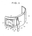
Fig. 1 is a perspective view of a counterweight and a filter showing a situation of inserting or taking out the filter in a first embodiment of the present invention; -
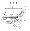
Fig. 2 is an enlarged sectional view by line II-II ofFig. 1 showing a state of mounting the filter; -
Fig. 3 is an enlarged sectional view by line III-III ofFig. 1 ; -
Fig. 4 is a further enlarged view showing a part in the state of mounting the filter; -
Fig. 5 is a view corresponding toFig. 4 showing a second embodiment of the present invention; -
Fig. 6 is a view corresponding toFig. 4 showing a third embodiment of the present invention; -
Fig. 7 is an enlarged vertically sectional view of a filter mounting portion showing a fourth embodiment of the present invention; -
Fig. 8 is a perspective view of a hydraulic excavator to which the present invention is applied seen from the rear side; -
Fig. 9 is a schematic plan view of the hydraulic excavator to which the present invention is applied; -
Fig. 10 is a partially enlarged view ofFig. 9 ; and -
Fig. 11 is a sectional view by line XI-XI inFig. 10 . - A description will be given to embodiments of the present invention with reference to
Figs. 1 to 7 . - In the embodiments below, a hydraulic excavator is an object to which the present invention is applied. An example thereof is a case where as shown in
Figs. 2 and3 , aduct 21 is provided in a front surface of acooler 6 installed in anengine room 3, and afilter 23 is mounted to afilter mounting portion 22 provided in a peripheral edge part of a tip of theduct 21. - The
filter 23 has a structure in which thefilter 23 is divided into anupper filter 24 and alower filter 25 on the upper and lower sides as well as thefilter 16 in the related art. Both thefilters filter mounting portion 22 in a state of being in contact with each other in the up and down direction. - As shown in
Figs. 1 to 3 , in acounterweight 26 also serving as a part of an external body for forming the engine room, are provided left andright maintenance ports maintenance panels Fig. 1 , thereference numeral 31 denotes hinges serving as opening and closing supporting points of the left maintenance panel 29). Thefilter 23 is inserted or taken out through theleft maintenance port 27 among the ports. - As means for easily performing the inserting and taking-out of the filter 23 (both the upper and
lower filters 24 and 25), cutouts (both upper and lower cutouts) 32 and 33 are provided in opening edge parts on both the upper and lower sides of theleft maintenance port 27 in thecounterweight 26. - The
upper cutout 32 is formed so as to have width for accepting passage of an upper end part of theupper filter 24, and thelower cutout 33 is formed so as to have width for accepting passage of a lower end part of thelower filter 25. By thecutouts filters - The
cutouts filters upper filter 24 and the lower end part of thelower filter 25 with thecutouts filters cutouts filter mounting portion 22. - A description will be given to means for mounting both the
filters filter mounting portion 22 with reference toFigs. 2 to 4 . - In the
filter mounting portion 22, are provided afilter abutment surface 22a facing towards the upstream side of the air flow around the entire periphery, and an elasticbody mounting portion 22b on the front end side which is the inner side seen from theleft maintenance port 27. In the elasticbody mounting portion 22b, is provided anelastic body 34 formed of a plate spring. - In the
elastic body 34, as shown inFig. 4 in detail, for each of both thefilters body mounting portion 22b in a state that a tip thereof opposes to thefilter abutment surface 22a. At the time of inserting the filter, theelastic body 34 is pushed in to the front side by an elastic body protector (elastic body protecting member) 35 provided in a front end part thereof. - By the above pushing-in effect, the
elastic body 34 is inclined so as to generate a restoring force (elastic force) F. As a component force thereof, a force (pressing force) F1 for pressing thefilters filter abutment surface 22a and a force (position fixing force) F2 for pushing thefilters - Meanwhile, on the rear end side of the
filters claw 36 protruding in a downwardly-turned shape is provided in thefilters hole 37 is provided in thefilter mounting portion 22. As shown in the figure, when thefilters claw 36 is automatically and elastically engaged with the engaginghole 37. - It should be noted that although both the
filters filters - The
elastic body 34 and the engagingclaw 36 and the engaginghole 37 may be provided at an intermediate position in the up and down direction of thefilters - By the above effect, both the
filters filter mounting portion 22 in a state of closely adhering to thefilter abutment surface 22a. - As mentioned above, according to the present structure, it is possible to press the
filters filter abutment surface 22a and fix the positions thereof by theelastic body 34. Therefore, in comparison to a conventional mounting structure of using a fastening tool such as a butterfly bolt, there is no need for a troublesome fastening operation and position fixing, and the fastening tool is not lost. - Since the restoring force of the
elastic body 34 works as the pressing force F1 and the position fixing force F2 to thefilters - That is, by a one-touch operation of pushing the rear end side in the arrow B direction after inserting the
filters filters - Therefore, an attachment and detachment work of the
filters -
- (i) since the
filters filter abutment surface 22a by the pressing force F1 from theelastic body 34, it is possible to ensure an airtightness (sealing property) between both the filters; and - (ii) since the position fixing force F2 by the
elastic body 34 works as a force in the direction of engaging the engagingclaw 36 with the engaginghole 37, an engagement state of both the engagingclaw 36 and the engaginghole 37 is reinforced. Therefore, it is possible to obtain a strong and stable filter mounting state, and there is no fear that thefilters - Meanwhile, the
cutouts filters left maintenance port 27 in thecounterweight 26. Therefore, it is possible to insert and take out thefilters counterweight 26 to a minimum which is only weight of thecutouts - That is, it is possible to satisfy a requirement of minimizing the
maintenance port 27 in order to ensure an original counterweight function of counter balance, and a requirement of ensuring space for inserting or taking out thefilters - Since the
cutouts - Further, in the case where the engaging
claw 36 and the engaginghole 37 are provided on the upper end side of theupper filter 24 and the lower end side of thelower filter 25, it is possible to easily perform a removing operation of the engagingclaw 36 from the engaginghole 37 by the upper andlower cutouts - A description will be only given to a different point from the first embodiment.
- In the first embodiment, the
elastic body 34 is provided on thefilter mounting portion 22 side, and theelastic body protector 35 is provided on thefilters Fig. 5 , theelastic body protector 35 is conversely provided on thefilter mounting portion 22 side, and the elastic body (plate spring in a substantially V shape seen from the top) 34 is provided on thefilters - In such a case, a point that the restoring force (elastic force) F works due to contact between the
elastic body 34 and theelastic body protector 35, and as the component force thereof, the pressing force F1 and the position fixing force F2 work is the same as the first embodiment. - In a third embodiment shown in
Fig. 6 , as theelastic body 34, a coil spring is used instead of the plate spring. The aboveelastic body 34 is mounted to thefilter mounting portion 22 through anelastic body receiver 38, and the restoring force F of theelastic body 34 and the component force thereof (pressing force F1 and the position fixing force F2) are generated by bringing theelastic body protector 35 into contact with theelastic body receiver 38. - It should be noted that the above configuration can be applied to a case where the
elastic body 34 is provided on thefilters elastic body protector 35 is provided on thefilter mounting portion 22 side as in the second embodiment. - In the above first to third embodiments, the restoring force F of the
elastic body 34 works on the front end side of thefilters Fig. 7 , theelastic bodies 34 are provided in an upper edge part and a lower edge part of thefilter mounting portion 22, and the restoring forces F thereof work in the up and down direction on the upper end side of theupper filter 24 and the lower end side of thelower filter 25. - In such a case, the working direction of the pressing force F1 serving as the component force is the same as the first to third embodiments.
- Meanwhile, the position fixing force F2 works downwards on the
upper filter 24 and upwards on thelower filter 25. By the force F2, both thefilters - It should be noted that in the case of the above configuration, a horizontal dividing member may be provided in a central part in the up and down direction of the
filter mounting portion 22, and both thefilters claw 36 and the engaginghole 37 used in the first to third embodiments may be provided. - The configuration of the fourth embodiment is particularly effective under a situation that the
filters filters -
- (1) The above embodiments exemplify a type in which the
filter 23 is divided into two on the upper and lower sides. However, the present invention can also be applied to a case where thefilter 23 is formed as a single filter.
Here, in the case where the restoring force F of theelastic body 34 works on the front end side of thefilter 23 as in the first to third embodiments shown inFigs. 1 to 6 , theelastic body 34 may be provided only in an intermediate part in the up and down direction of the filter, or may be provided on both the upper and lower sides. Alternatively, theelastic body 34 may be provided on both the upper and lower sides and the intermediate part.
Meanwhile, in the case where the restoring force F of theelastic body 34 works in the up and down direction as in the fourth embodiment shown inFig. 7 , the configuration of the above embodiment in which theelastic bodies 34 are provided on both the upper and lower sides may be directly applied to the single filter. In such a case, the position fixing forces F2 in the up and down direction serving as the component forces of the restoring forces F of theelastic bodies 34 on both the upper and lower sides work on thesingle filter 23 as a compression force in the up and down direction, and by the compression force, the position of thefilter 23 is fixed.
Alternatively, the configuration of the first to third embodiments is adopted, and for example, theelastic body 34 may be provided on the upper end side of thesingle filter 23 and the engagingclaw 36 and the engaginghole 37 may be provided on the lower end side. - (2) The
filter 23 is formed by mounting a filter frame on a circumference of a filter main body as mentioned above including a type of dividing into two on the upper and lower sides. In the above configuration, as means for smoothly performing an operation of inserting and taking out thefilter 23, a smooth material with low coefficient of friction such as nylon resin may be used as the filter frame, or the above material may be adhered to the entire surface or an important point of the filter frame. - (3) As the
elastic body 34, instead of a spring body such as the plate spring and the coil spring in the above embodiment, a rubber in a thick plate shape or a block shape with high elasticity may be used. In such a case, a metal plate for preventing abrasion is desirably provided on a surface of the rubber. - Although the invention has been described with reference to the preferred embodiments in the attached figures, it is noted that equivalents may be employed and substitutions made herein without departing from the scope of the invention as recited in the claims.
- On the front surface side of a cooler, a filter mounting portion provided with a filter abutment surface with which a filter is brought into abutment from the front side of the filter mounting portion is provided. The front end side of the filter pushed in from a maintenance port is pressed onto an elastic body formed of a plate spring and provided in the filter mounting portion. Thereby, by a pressing force F1 serving as a component force of a restoring force F of the elastic body, the filter is pressed onto the filter abutment surface, and by a position fixing force F2, the filter is pushed rearwards so as to ensure an engagement state of an engaging claw and an engaging hole.
Claims (8)
- A mounting structure of filter for cooler of construction machine detachably mounted on the front surface side of the cooler installed in an engine room of an upper rotating body disposed on a lower traveling body, comprising:a filter mounting portion provided on the front surface side of the cooler, the filter mounting portion being provided with a filter abutment surface with which the filter is brought into abutment from the front side of the filter mounting portion;an external body for forming the engine room, the external body being provided with a maintenance port into or from which the filter is inserted or taken out; andan elastic body for exerting an elastic force in the direction of fixing a position of the filter inserted from the maintenance port to said filter mounting portion in a state that the filter is pressed onto the filter abutment surface.
- The mounting structure of filter for cooler of construction machine according to claim 1, wherein
the filter is provided in the front and rear direction of the upper rotating body, while said elastic body is provided in a state of exerting a pressing force of pressing the filter onto the filter abutment surface on the front end side of the filter and a position fixing force of pushing the filter rearwards. - The mounting structure of filter for cooler of construction machine according to claim 2, wherein
an engaging claw is provided in one of a rear end part of the filter and said filter mounting portion, an engaging hole is provided in the other, and the position fixing force of said elastic body works as a force in the direction of engaging the engaging claw with the engaging hole. - The mounting structure of filter for cooler of construction machine according to claim 2, wherein
a counterweight also serving as a part of said external body is provided in a rear end part of the upper rotating body, a maintenance port is provided in the counterweight, and cutouts for accepting passage of the filter at the time of inserting or taking out the filter are provided in opening edge parts on both the upper and lower sides of the maintenance port. - The mounting structure of filter for cooler of construction machine according to claim 1, wherein
the filter is provided in the front and rear direction of the upper rotating body, and said elastic body is provided in a state of exerting a pressing force of pressing the filter onto the filter abutment surface on the one end side in the up and down direction of the filter, and a position fixing force in the up and down direction. - The mounting structure of filter for cooler of construction machine according to claim 1, wherein
a duct for bringing the air taken from the exterior to the cooler is provided on the front surface side of the cooler, and said filter mounting portion is provided in a tip of the duct. - The mounting structure of filter for cooler of construction machine according to claim 1, wherein
the filter is divided into an upper filter and a lower filter on the upper and lower sides respectively, and elastic bodies are provided in both the filters respectively. - The mounting structure of filter for cooler of construction machine according to claim 1, wherein
a plate spring serving as said elastic body is provided in one of the filter and said filter mounting portion, and an elastic body protector brought in contact with the plate spring for transmitting a pressing force and a position fixing force to the filter is provided in the other.
Applications Claiming Priority (1)
| Application Number | Priority Date | Filing Date | Title |
|---|---|---|---|
| JP2007044098A JP4501945B2 (en) | 2007-02-23 | 2007-02-23 | Construction structure of filter for cooler of construction machine |
Publications (3)
| Publication Number | Publication Date |
|---|---|
| EP1961868A2 true EP1961868A2 (en) | 2008-08-27 |
| EP1961868A3 EP1961868A3 (en) | 2010-03-24 |
| EP1961868B1 EP1961868B1 (en) | 2020-06-10 |
Family
ID=39301154
Family Applications (1)
| Application Number | Title | Priority Date | Filing Date |
|---|---|---|---|
| EP08151727.8A Active EP1961868B1 (en) | 2007-02-23 | 2008-02-21 | Mounting structure of filter for cooler of construction machine |
Country Status (4)
| Country | Link |
|---|---|
| US (1) | US7833300B2 (en) |
| EP (1) | EP1961868B1 (en) |
| JP (1) | JP4501945B2 (en) |
| CN (1) | CN101250887B (en) |
Cited By (4)
| Publication number | Priority date | Publication date | Assignee | Title |
|---|---|---|---|---|
| EP2295758A1 (en) * | 2009-07-29 | 2011-03-16 | Hitachi Construction Machinery Co., Ltd. | Installation structure for dustproof net |
| JP2013083059A (en) * | 2011-10-07 | 2013-05-09 | Sumitomo (Shi) Construction Machinery Co Ltd | Filter device for construction machine |
| EP2685081A1 (en) * | 2012-07-09 | 2014-01-15 | MANN+HUMMEL GmbH | Air cleaner in particular of an internal combustion engine |
| WO2015086661A1 (en) * | 2013-12-10 | 2015-06-18 | Mann+Hummel Gmbh | Cabin air filter and filter assembly |
Families Citing this family (23)
| Publication number | Priority date | Publication date | Assignee | Title |
|---|---|---|---|---|
| JP4667141B2 (en) * | 2005-07-05 | 2011-04-06 | ヤンマー株式会社 | Swivel work vehicle |
| JP2008248848A (en) * | 2007-03-30 | 2008-10-16 | Denso Corp | Air cleaner for internal combustion engine |
| IT1393983B1 (en) * | 2009-04-27 | 2012-05-17 | Ufi Filters Spa | AIR FILTER UNIT FOR MOTOR VEHICLES AND FILTER ELEMENT |
| JP5810784B2 (en) * | 2011-09-16 | 2015-11-11 | コベルコ建機株式会社 | Construction machinery |
| JP5510466B2 (en) * | 2012-01-10 | 2014-06-04 | コベルコ建機株式会社 | Construction machinery |
| JP5527334B2 (en) * | 2012-01-10 | 2014-06-18 | コベルコ建機株式会社 | Construction machinery |
| US8734572B2 (en) | 2012-04-03 | 2014-05-27 | Bha Altair, Llc | Quick engagement method for gas turbine inlet filter installation and replacement |
| JP5533934B2 (en) * | 2012-05-09 | 2014-06-25 | コベルコ建機株式会社 | Construction machine filter mounting structure |
| CN103509896B (en) * | 2012-06-20 | 2015-10-28 | 上海梅山钢铁股份有限公司 | A kind of examination and repair method of blast furnace granulated slag effuser |
| WO2014064852A1 (en) * | 2012-10-26 | 2014-05-01 | 株式会社小松製作所 | Wheel loader |
| DE102014004740A1 (en) * | 2014-04-01 | 2015-10-01 | Daimler Ag | Air filter for a ventilation device of a motor vehicle |
| CN106573531A (en) * | 2014-05-28 | 2017-04-19 | 威克斯科技有限责任公司 | Air-cooled heat exchange system |
| US9567949B2 (en) | 2015-01-09 | 2017-02-14 | Mann+Hummel Gmbh | Air cleaner in particular of an internal combustion engine |
| KR102249595B1 (en) * | 2017-05-16 | 2021-05-10 | 현대자동차 주식회사 | Air cleaner unit for vehicles |
| JP6793671B2 (en) * | 2018-02-15 | 2020-12-02 | 日立建機株式会社 | Construction machinery |
| JP6912420B2 (en) * | 2018-05-25 | 2021-08-04 | 日立建機株式会社 | Construction machinery |
| JP2019203349A (en) * | 2018-05-25 | 2019-11-28 | 日立建機株式会社 | Construction machine |
| JP7179590B2 (en) * | 2018-11-21 | 2022-11-29 | 株式会社小松製作所 | work vehicle |
| JP7260311B2 (en) | 2019-01-31 | 2023-04-18 | コベルコ建機株式会社 | construction machinery |
| FR3093164A1 (en) * | 2019-02-25 | 2020-08-28 | Valeo Systemes Thermiques | Housing for heating, air conditioning and / or ventilation device for motor vehicle |
| JP7058237B2 (en) * | 2019-03-11 | 2022-04-21 | 株式会社日立建機ティエラ | Construction machinery |
| CN109973263B (en) * | 2019-03-19 | 2021-02-09 | 武汉科珈种业科技有限公司 | Air inlet device of combine harvester |
| EP3771870A1 (en) * | 2019-07-31 | 2021-02-03 | Electrolux Appliances Aktiebolag | Filter cartridge for a filter assembly, filter assembly and domestic appliance with a filter assemly |
Citations (2)
| Publication number | Priority date | Publication date | Assignee | Title |
|---|---|---|---|---|
| JP2001342645A (en) | 2000-05-31 | 2001-12-14 | Yanmar Diesel Engine Co Ltd | Excavation work vehicle |
| JP2006052689A (en) | 2004-08-12 | 2006-02-23 | Kobelco Contstruction Machinery Ltd | Cooling device for construction machine |
Family Cites Families (17)
| Publication number | Priority date | Publication date | Assignee | Title |
|---|---|---|---|---|
| JPS49146331U (en) * | 1973-04-16 | 1974-12-17 | ||
| JPH0193328A (en) | 1987-10-06 | 1989-04-12 | Fujimori Kogyo Kk | Manufacture of cylindrical vessel |
| JPH0452436Y2 (en) * | 1987-12-10 | 1992-12-09 | ||
| JPH0193328U (en) * | 1987-12-14 | 1989-06-20 | ||
| JPH043827A (en) | 1990-04-17 | 1992-01-08 | Matsushita Electric Ind Co Ltd | Housing equipment device |
| JPH043827U (en) * | 1990-04-25 | 1992-01-14 | ||
| US5399180A (en) * | 1993-12-06 | 1995-03-21 | Kopp; John G. | Modular filter assembly |
| DE19638790A1 (en) * | 1996-09-21 | 1998-03-26 | Mann & Hummel Filter | Air filter |
| JP2001260947A (en) * | 2000-03-23 | 2001-09-26 | Kubota Corp | Hood device for rotary work machine |
| JP2006052690A (en) * | 2004-08-12 | 2006-02-23 | Kobelco Contstruction Machinery Ltd | Cooling device of construction machine, filter for cooling device, and filter mounting method |
| JP4523360B2 (en) | 2004-08-17 | 2010-08-11 | 日立建機株式会社 | Construction machinery cab |
| JP4563768B2 (en) * | 2004-10-15 | 2010-10-13 | 本田技研工業株式会社 | Air cleaner |
| JP4238206B2 (en) * | 2004-12-16 | 2009-03-18 | キャタピラージャパン株式会社 | Work machine cooling system |
| CN101069002B (en) | 2004-12-27 | 2010-10-13 | 神钢建设机械株式会社 | Cooling structure of construction machine |
| JP4506665B2 (en) * | 2004-12-27 | 2010-07-21 | コベルコ建機株式会社 | Construction machine cooling structure |
| JP2006242077A (en) | 2005-03-02 | 2006-09-14 | Hitachi Constr Mach Co Ltd | Heat exchange device for construction machine |
| JP2006328665A (en) * | 2005-05-23 | 2006-12-07 | Kobelco Contstruction Machinery Ltd | Filter device of construction machinery |
-
2007
- 2007-02-23 JP JP2007044098A patent/JP4501945B2/en active Active
-
2008
- 2008-02-21 US US12/035,081 patent/US7833300B2/en active Active
- 2008-02-21 EP EP08151727.8A patent/EP1961868B1/en active Active
- 2008-02-22 CN CN2008100814606A patent/CN101250887B/en active Active
Patent Citations (2)
| Publication number | Priority date | Publication date | Assignee | Title |
|---|---|---|---|---|
| JP2001342645A (en) | 2000-05-31 | 2001-12-14 | Yanmar Diesel Engine Co Ltd | Excavation work vehicle |
| JP2006052689A (en) | 2004-08-12 | 2006-02-23 | Kobelco Contstruction Machinery Ltd | Cooling device for construction machine |
Cited By (5)
| Publication number | Priority date | Publication date | Assignee | Title |
|---|---|---|---|---|
| EP2295758A1 (en) * | 2009-07-29 | 2011-03-16 | Hitachi Construction Machinery Co., Ltd. | Installation structure for dustproof net |
| JP2013083059A (en) * | 2011-10-07 | 2013-05-09 | Sumitomo (Shi) Construction Machinery Co Ltd | Filter device for construction machine |
| EP2685081A1 (en) * | 2012-07-09 | 2014-01-15 | MANN+HUMMEL GmbH | Air cleaner in particular of an internal combustion engine |
| WO2014009039A1 (en) * | 2012-07-09 | 2014-01-16 | Mann+Hummel Gmbh | Air cleaner in particular of an internal combustion engine |
| WO2015086661A1 (en) * | 2013-12-10 | 2015-06-18 | Mann+Hummel Gmbh | Cabin air filter and filter assembly |
Also Published As
| Publication number | Publication date |
|---|---|
| US7833300B2 (en) | 2010-11-16 |
| EP1961868B1 (en) | 2020-06-10 |
| JP4501945B2 (en) | 2010-07-14 |
| CN101250887A (en) | 2008-08-27 |
| JP2008208551A (en) | 2008-09-11 |
| CN101250887B (en) | 2012-11-28 |
| US20080202451A1 (en) | 2008-08-28 |
| EP1961868A3 (en) | 2010-03-24 |
Similar Documents
| Publication | Publication Date | Title |
|---|---|---|
| EP1961868B1 (en) | Mounting structure of filter for cooler of construction machine | |
| US20220412200A1 (en) | Cover Assembly, Pipe Assembly and Turbine Fracturing Unit | |
| EP2615211B1 (en) | Construction machine | |
| EP2436547B1 (en) | Mounting arrangement for tractor front grille to shroud | |
| EP1247908B1 (en) | Radiator for earth moving machine | |
| JP6115960B2 (en) | Hood equipment and work machine | |
| JP2014144678A (en) | Work machine | |
| EP1462578A2 (en) | Working machine | |
| KR101081633B1 (en) | Cooling device of construction machine | |
| US20140138066A1 (en) | Cooling package for a machine | |
| JP2001012246A (en) | Connection and disconnection structure of radiator dust protective net on machinery for working | |
| US20140216833A1 (en) | Work vehicle | |
| JP6793671B2 (en) | Construction machinery | |
| CN220162336U (en) | Transparent tool for heat pump assembly | |
| KR200477506Y1 (en) | Back-surface facing machine of main engine joining part | |
| JP4474229B2 (en) | Engine room of construction machinery | |
| JP2018123640A (en) | Construction machine | |
| KR200492107Y1 (en) | Dustproof assembly for linear actuator | |
| JP4082320B2 (en) | Radiator ventilation structure of construction machinery | |
| JP2000054430A (en) | Construction machine cooling device and battery protective cover | |
| CN210046502U (en) | Cell-phone glass processing positioning jig | |
| JPS6131857Y2 (en) | ||
| JPH0648122Y2 (en) | Engine cover opening and closing device | |
| CN2768143Y (en) | Mounting tool for small-sized hard disk ramp | |
| JP2003322488A (en) | Heat exchanger of construction machine |
Legal Events
| Date | Code | Title | Description |
|---|---|---|---|
| PUAI | Public reference made under article 153(3) epc to a published international application that has entered the european phase |
Free format text: ORIGINAL CODE: 0009012 |
|
| 17P | Request for examination filed |
Effective date: 20080221 |
|
| AK | Designated contracting states |
Kind code of ref document: A2 Designated state(s): AT BE BG CH CY CZ DE DK EE ES FI FR GB GR HR HU IE IS IT LI LT LU LV MC MT NL NO PL PT RO SE SI SK TR |
|
| AX | Request for extension of the european patent |
Extension state: AL BA MK RS |
|
| PUAL | Search report despatched |
Free format text: ORIGINAL CODE: 0009013 |
|
| AK | Designated contracting states |
Kind code of ref document: A3 Designated state(s): AT BE BG CH CY CZ DE DK EE ES FI FR GB GR HR HU IE IS IT LI LT LU LV MC MT NL NO PL PT RO SE SI SK TR |
|
| AX | Request for extension of the european patent |
Extension state: AL BA MK RS |
|
| 17Q | First examination report despatched |
Effective date: 20101022 |
|
| AKX | Designation fees paid |
Designated state(s): AT BE BG CH CY CZ DE DK EE ES FI FR GB GR HR HU IE IS IT LI LT LU LV MC MT NL NO PL PT RO SE SI SK TR |
|
| STAA | Information on the status of an ep patent application or granted ep patent |
Free format text: STATUS: EXAMINATION IS IN PROGRESS |
|
| REG | Reference to a national code |
Ref country code: DE Ref legal event code: R079 Ref document number: 602008062829 Country of ref document: DE Free format text: PREVIOUS MAIN CLASS: E02F0009080000 Ipc: E02F0009000000 |
|
| RIC1 | Information provided on ipc code assigned before grant |
Ipc: F01P 11/12 20060101ALI20191205BHEP Ipc: E02F 9/00 20060101AFI20191205BHEP Ipc: E02F 9/08 20060101ALI20191205BHEP Ipc: B60K 11/02 20060101ALI20191205BHEP |
|
| GRAP | Despatch of communication of intention to grant a patent |
Free format text: ORIGINAL CODE: EPIDOSNIGR1 |
|
| STAA | Information on the status of an ep patent application or granted ep patent |
Free format text: STATUS: GRANT OF PATENT IS INTENDED |
|
| RIN1 | Information on inventor provided before grant (corrected) |
Inventor name: YONEZAWA, KOJI Inventor name: TANIUCHI, TOMOYA |
|
| INTG | Intention to grant announced |
Effective date: 20200110 |
|
| GRAS | Grant fee paid |
Free format text: ORIGINAL CODE: EPIDOSNIGR3 |
|
| GRAA | (expected) grant |
Free format text: ORIGINAL CODE: 0009210 |
|
| STAA | Information on the status of an ep patent application or granted ep patent |
Free format text: STATUS: THE PATENT HAS BEEN GRANTED |
|
| AK | Designated contracting states |
Kind code of ref document: B1 Designated state(s): AT BE BG CH CY CZ DE DK EE ES FI FR GB GR HR HU IE IS IT LI LT LU LV MC MT NL NO PL PT RO SE SI SK TR |
|
| REG | Reference to a national code |
Ref country code: GB Ref legal event code: FG4D |
|
| REG | Reference to a national code |
Ref country code: AT Ref legal event code: REF Ref document number: 1279297 Country of ref document: AT Kind code of ref document: T Effective date: 20200615 Ref country code: CH Ref legal event code: EP |
|
| REG | Reference to a national code |
Ref country code: DE Ref legal event code: R096 Ref document number: 602008062829 Country of ref document: DE |
|
| REG | Reference to a national code |
Ref country code: IE Ref legal event code: FG4D |
|
| REG | Reference to a national code |
Ref country code: LT Ref legal event code: MG4D |
|
| PG25 | Lapsed in a contracting state [announced via postgrant information from national office to epo] |
Ref country code: LT Free format text: LAPSE BECAUSE OF FAILURE TO SUBMIT A TRANSLATION OF THE DESCRIPTION OR TO PAY THE FEE WITHIN THE PRESCRIBED TIME-LIMIT Effective date: 20200610 Ref country code: SE Free format text: LAPSE BECAUSE OF FAILURE TO SUBMIT A TRANSLATION OF THE DESCRIPTION OR TO PAY THE FEE WITHIN THE PRESCRIBED TIME-LIMIT Effective date: 20200610 Ref country code: GR Free format text: LAPSE BECAUSE OF FAILURE TO SUBMIT A TRANSLATION OF THE DESCRIPTION OR TO PAY THE FEE WITHIN THE PRESCRIBED TIME-LIMIT Effective date: 20200911 Ref country code: NO Free format text: LAPSE BECAUSE OF FAILURE TO SUBMIT A TRANSLATION OF THE DESCRIPTION OR TO PAY THE FEE WITHIN THE PRESCRIBED TIME-LIMIT Effective date: 20200910 Ref country code: FI Free format text: LAPSE BECAUSE OF FAILURE TO SUBMIT A TRANSLATION OF THE DESCRIPTION OR TO PAY THE FEE WITHIN THE PRESCRIBED TIME-LIMIT Effective date: 20200610 |
|
| REG | Reference to a national code |
Ref country code: NL Ref legal event code: MP Effective date: 20200610 |
|
| PG25 | Lapsed in a contracting state [announced via postgrant information from national office to epo] |
Ref country code: LV Free format text: LAPSE BECAUSE OF FAILURE TO SUBMIT A TRANSLATION OF THE DESCRIPTION OR TO PAY THE FEE WITHIN THE PRESCRIBED TIME-LIMIT Effective date: 20200610 Ref country code: HR Free format text: LAPSE BECAUSE OF FAILURE TO SUBMIT A TRANSLATION OF THE DESCRIPTION OR TO PAY THE FEE WITHIN THE PRESCRIBED TIME-LIMIT Effective date: 20200610 Ref country code: BG Free format text: LAPSE BECAUSE OF FAILURE TO SUBMIT A TRANSLATION OF THE DESCRIPTION OR TO PAY THE FEE WITHIN THE PRESCRIBED TIME-LIMIT Effective date: 20200910 |
|
| REG | Reference to a national code |
Ref country code: AT Ref legal event code: MK05 Ref document number: 1279297 Country of ref document: AT Kind code of ref document: T Effective date: 20200610 |
|
| PG25 | Lapsed in a contracting state [announced via postgrant information from national office to epo] |
Ref country code: NL Free format text: LAPSE BECAUSE OF FAILURE TO SUBMIT A TRANSLATION OF THE DESCRIPTION OR TO PAY THE FEE WITHIN THE PRESCRIBED TIME-LIMIT Effective date: 20200610 |
|
| PG25 | Lapsed in a contracting state [announced via postgrant information from national office to epo] |
Ref country code: CZ Free format text: LAPSE BECAUSE OF FAILURE TO SUBMIT A TRANSLATION OF THE DESCRIPTION OR TO PAY THE FEE WITHIN THE PRESCRIBED TIME-LIMIT Effective date: 20200610 Ref country code: EE Free format text: LAPSE BECAUSE OF FAILURE TO SUBMIT A TRANSLATION OF THE DESCRIPTION OR TO PAY THE FEE WITHIN THE PRESCRIBED TIME-LIMIT Effective date: 20200610 Ref country code: RO Free format text: LAPSE BECAUSE OF FAILURE TO SUBMIT A TRANSLATION OF THE DESCRIPTION OR TO PAY THE FEE WITHIN THE PRESCRIBED TIME-LIMIT Effective date: 20200610 Ref country code: PT Free format text: LAPSE BECAUSE OF FAILURE TO SUBMIT A TRANSLATION OF THE DESCRIPTION OR TO PAY THE FEE WITHIN THE PRESCRIBED TIME-LIMIT Effective date: 20201012 Ref country code: ES Free format text: LAPSE BECAUSE OF FAILURE TO SUBMIT A TRANSLATION OF THE DESCRIPTION OR TO PAY THE FEE WITHIN THE PRESCRIBED TIME-LIMIT Effective date: 20200610 Ref country code: AT Free format text: LAPSE BECAUSE OF FAILURE TO SUBMIT A TRANSLATION OF THE DESCRIPTION OR TO PAY THE FEE WITHIN THE PRESCRIBED TIME-LIMIT Effective date: 20200610 |
|
| PG25 | Lapsed in a contracting state [announced via postgrant information from national office to epo] |
Ref country code: IS Free format text: LAPSE BECAUSE OF FAILURE TO SUBMIT A TRANSLATION OF THE DESCRIPTION OR TO PAY THE FEE WITHIN THE PRESCRIBED TIME-LIMIT Effective date: 20201010 Ref country code: SK Free format text: LAPSE BECAUSE OF FAILURE TO SUBMIT A TRANSLATION OF THE DESCRIPTION OR TO PAY THE FEE WITHIN THE PRESCRIBED TIME-LIMIT Effective date: 20200610 Ref country code: PL Free format text: LAPSE BECAUSE OF FAILURE TO SUBMIT A TRANSLATION OF THE DESCRIPTION OR TO PAY THE FEE WITHIN THE PRESCRIBED TIME-LIMIT Effective date: 20200610 |
|
| REG | Reference to a national code |
Ref country code: DE Ref legal event code: R097 Ref document number: 602008062829 Country of ref document: DE |
|
| PLBE | No opposition filed within time limit |
Free format text: ORIGINAL CODE: 0009261 |
|
| STAA | Information on the status of an ep patent application or granted ep patent |
Free format text: STATUS: NO OPPOSITION FILED WITHIN TIME LIMIT |
|
| PG25 | Lapsed in a contracting state [announced via postgrant information from national office to epo] |
Ref country code: DK Free format text: LAPSE BECAUSE OF FAILURE TO SUBMIT A TRANSLATION OF THE DESCRIPTION OR TO PAY THE FEE WITHIN THE PRESCRIBED TIME-LIMIT Effective date: 20200610 |
|
| 26N | No opposition filed |
Effective date: 20210311 |
|
| PG25 | Lapsed in a contracting state [announced via postgrant information from national office to epo] |
Ref country code: SI Free format text: LAPSE BECAUSE OF FAILURE TO SUBMIT A TRANSLATION OF THE DESCRIPTION OR TO PAY THE FEE WITHIN THE PRESCRIBED TIME-LIMIT Effective date: 20200610 |
|
| PG25 | Lapsed in a contracting state [announced via postgrant information from national office to epo] |
Ref country code: MC Free format text: LAPSE BECAUSE OF FAILURE TO SUBMIT A TRANSLATION OF THE DESCRIPTION OR TO PAY THE FEE WITHIN THE PRESCRIBED TIME-LIMIT Effective date: 20200610 |
|
| REG | Reference to a national code |
Ref country code: BE Ref legal event code: MM Effective date: 20210228 |
|
| PG25 | Lapsed in a contracting state [announced via postgrant information from national office to epo] |
Ref country code: CH Free format text: LAPSE BECAUSE OF NON-PAYMENT OF DUE FEES Effective date: 20210228 Ref country code: LU Free format text: LAPSE BECAUSE OF NON-PAYMENT OF DUE FEES Effective date: 20210221 Ref country code: LI Free format text: LAPSE BECAUSE OF NON-PAYMENT OF DUE FEES Effective date: 20210228 |
|
| PG25 | Lapsed in a contracting state [announced via postgrant information from national office to epo] |
Ref country code: IE Free format text: LAPSE BECAUSE OF NON-PAYMENT OF DUE FEES Effective date: 20210221 |
|
| PG25 | Lapsed in a contracting state [announced via postgrant information from national office to epo] |
Ref country code: BE Free format text: LAPSE BECAUSE OF NON-PAYMENT OF DUE FEES Effective date: 20210228 |
|
| PG25 | Lapsed in a contracting state [announced via postgrant information from national office to epo] |
Ref country code: HU Free format text: LAPSE BECAUSE OF FAILURE TO SUBMIT A TRANSLATION OF THE DESCRIPTION OR TO PAY THE FEE WITHIN THE PRESCRIBED TIME-LIMIT; INVALID AB INITIO Effective date: 20080221 Ref country code: CY Free format text: LAPSE BECAUSE OF FAILURE TO SUBMIT A TRANSLATION OF THE DESCRIPTION OR TO PAY THE FEE WITHIN THE PRESCRIBED TIME-LIMIT Effective date: 20200610 |
|
| PGFP | Annual fee paid to national office [announced via postgrant information from national office to epo] |
Ref country code: IT Payment date: 20230110 Year of fee payment: 16 |
|
| PGFP | Annual fee paid to national office [announced via postgrant information from national office to epo] |
Ref country code: DE Payment date: 20231228 Year of fee payment: 17 Ref country code: GB Payment date: 20240108 Year of fee payment: 17 |
|
| PGFP | Annual fee paid to national office [announced via postgrant information from national office to epo] |
Ref country code: FR Payment date: 20240103 Year of fee payment: 17 |
|
| PG25 | Lapsed in a contracting state [announced via postgrant information from national office to epo] |
Ref country code: TR Free format text: LAPSE BECAUSE OF FAILURE TO SUBMIT A TRANSLATION OF THE DESCRIPTION OR TO PAY THE FEE WITHIN THE PRESCRIBED TIME-LIMIT Effective date: 20200610 |