EP1950880A2 - Dünne Anzeigevorrichtung - Google Patents
Dünne Anzeigevorrichtung Download PDFInfo
- Publication number
- EP1950880A2 EP1950880A2 EP08001316A EP08001316A EP1950880A2 EP 1950880 A2 EP1950880 A2 EP 1950880A2 EP 08001316 A EP08001316 A EP 08001316A EP 08001316 A EP08001316 A EP 08001316A EP 1950880 A2 EP1950880 A2 EP 1950880A2
- Authority
- EP
- European Patent Office
- Prior art keywords
- motor
- operating voltage
- signal
- driving
- motor driver
- Prior art date
- Legal status (The legal status is an assumption and is not a legal conclusion. Google has not performed a legal analysis and makes no representation as to the accuracy of the status listed.)
- Withdrawn
Links
Images


Classifications
-
- F—MECHANICAL ENGINEERING; LIGHTING; HEATING; WEAPONS; BLASTING
- F16—ENGINEERING ELEMENTS AND UNITS; GENERAL MEASURES FOR PRODUCING AND MAINTAINING EFFECTIVE FUNCTIONING OF MACHINES OR INSTALLATIONS; THERMAL INSULATION IN GENERAL
- F16M—FRAMES, CASINGS OR BEDS OF ENGINES, MACHINES OR APPARATUS, NOT SPECIFIC TO ENGINES, MACHINES OR APPARATUS PROVIDED FOR ELSEWHERE; STANDS; SUPPORTS
- F16M11/00—Stands or trestles as supports for apparatus or articles placed thereon ; Stands for scientific apparatus such as gravitational force meters
- F16M11/02—Heads
- F16M11/04—Means for attachment of apparatus; Means allowing adjustment of the apparatus relatively to the stand
- F16M11/06—Means for attachment of apparatus; Means allowing adjustment of the apparatus relatively to the stand allowing pivoting
- F16M11/08—Means for attachment of apparatus; Means allowing adjustment of the apparatus relatively to the stand allowing pivoting around a vertical axis, e.g. panoramic heads
-
- F—MECHANICAL ENGINEERING; LIGHTING; HEATING; WEAPONS; BLASTING
- F16—ENGINEERING ELEMENTS AND UNITS; GENERAL MEASURES FOR PRODUCING AND MAINTAINING EFFECTIVE FUNCTIONING OF MACHINES OR INSTALLATIONS; THERMAL INSULATION IN GENERAL
- F16M—FRAMES, CASINGS OR BEDS OF ENGINES, MACHINES OR APPARATUS, NOT SPECIFIC TO ENGINES, MACHINES OR APPARATUS PROVIDED FOR ELSEWHERE; STANDS; SUPPORTS
- F16M11/00—Stands or trestles as supports for apparatus or articles placed thereon ; Stands for scientific apparatus such as gravitational force meters
- F16M11/02—Heads
- F16M11/18—Heads with mechanism for moving the apparatus relatively to the stand
-
- H—ELECTRICITY
- H04—ELECTRIC COMMUNICATION TECHNIQUE
- H04N—PICTORIAL COMMUNICATION, e.g. TELEVISION
- H04N5/00—Details of television systems
- H04N5/64—Constructional details of receivers, e.g. cabinets or dust covers
Definitions
- the present invention relates to a thin type display device where as its display portion is made of a thin type by various methods such as a liquid crystal method, a plasma method, a rear projection method or the like, in particular, the present invention relates to a thin type display device which is provided with a rotation driving mechanism (swivel mechanism) to make the display portion rotate in horizontal direction.
- a rotation driving mechanism tilt mechanism
- a display device which is provided with a rotation driving mechanism (swivel mechanism) to rotate a display portion by transmitting rotating force of a motor in order to rotate the display portion on which an image is displayed to reproduce in horizontal direction.
- rotation driving mechanism not only mechanism that is formed for a display device in which the display portion is composed of a Braun tube (See, JP-UM-A-S63-124775 , JP-UM-A-H03-042186 , JP-A-H04-061575 ), but recently mechanism that is formed for a thin type display device in which the display portion is made a thin type by various methods such as a liquid crystal method, a plasma method, a rear projection method, or the like (See, JP-A-2004-304679 ), is also proposed.
- the rotation driving mechanism that is disclosed in JP-UM-AH03-042186 , it has a structure in that an electromagnetic clutch is controlled in response to magnitude of loaded electric current when a driving motor is operated in order that stopping of rotating operation or appropriate control can be performed if the display portion collides with an obstruction when it is rotating. That is, because the loaded electric current of the driving motor becomes large when the display portion collides with the obstruction, the mechanism detects the collision with the obstruction based on the loaded electric current, and rotation of the display portion is stopped by cut off of the electromagnetic clutch.
- the rotation driving mechanism that is disclosed in JP-AH04-061575 , it has a structure in that the rotation driving mechanism is provided with a stepping motor which can easily obtain low speed rotation and high torque instead that it is provided with a small direct current motor which has small torque and a power transmission path with high gear ratio in order to secure high torque that is required to rotate the display portion of the display device which becomes larger and larger.
- the gear ratio of the power transmission path can be lowered and its configuration can be made simple by providing with the stepping motor, the configuration of the rotation driving mechanism also can be made simple.
- the rotation driving mechanism that is disclosed in JP-A-2004-304679 , the stepping motor is utilized and the rotation driving mechanism is structured as a swivel and tilting mechanism which can rotate the display portion of the thin type display device in horizontal direction and in tilt direction respectively.
- the above described rotation driving mechanism is arranged in the thin type display device, if the thin type display device is set up on floor provided with the rotation driving mechanism, and the swivel mechanism portion which makes the display portion rotate in the horizontal direction is driven, vibration is caused in whole device by starting or stopping of the rotating operation because center of gravity of the display portion is high. Especially when the display portion is stopped immediately after the display portion is started to rotate by the swivel mechanism in the horizontal direction, the vibration that is caused in the display portion becomes large.
- a rotation driving mechanism disclosed in JP-A-H04-061575 employs a structure in that the vibration that is caused by affection of such inertia and the like is prevented mechanically using a leaf spring or the like arranged in a space which is made around upper part of rotating axis.
- a leaf spring or the like arranged in a space which is made around upper part of rotating axis.
- a thin type display device in accordance with the present invention includes: a display portion which is equipped with a screen to display image; a pedestal portion to support the display portion; a connecting portion to connect the pedestal portion and the display portion; a swivel mechanism which is set up in the connecting portion to rotate the display portion in horizontal direction; a motor which gives rotating force to the swivel mechanism; an infrared light receiving portion which receives an infrared signal output from a remote controller for instructing operations to instruct driving of the swivel mechanism; a signal converting portion which converts the infrared signal that is received in the infrared light receiving portion into a control signal; a main control portion which confirms content of the instruction by analyzing the control signal from the signal converting portion; a motor driver to drive the motor by a signal output from the main control portion; and an operating voltage control portion to which a signal is input from the main control portion and generates a voltage switching signal to switch operating voltage of the motor that is supplied from the
- a thin type display device in accordance with the present invention includes: a display portion which is equipped with a screen to display image; a pedestal portion to support the display portion; a connecting portion to connect the pedestal portion and the display portion; a swivel mechanism which is set up in the connecting portion to rotate the display portion in horizontal direction; a motor which gives rotating force to the swivel mechanism; a motor driver to drive the motor; and an operating voltage control portion which generates a voltage switching signal to switch operating voltage of the motor that is supplied from the motor driver, and the device is characterized by that when driving of the swivel mechanism is started, the operating voltage that is supplied from the motor driver is switched and raised in stepwise by the voltage switching signal from the operating voltage control portion and the operating voltage is made a maximum value after a prescribed time length is passed from the starting of driving.
- the operating voltage from the motor driver is switched by that the operating voltage control portion switches value of bias voltage which is supplied to the motor driver.
- the motor driver is equipped with a control terminal to switch the operating voltage of the motor, and the operating voltage from the motor driver is switched by that value of a signal that is output from the operating voltage control portion to the control terminal of the motor driver is switched.
- the operating voltage control portion is composed of a digital-analog conversion circuit and a digital signal to instruct the operating voltage is converted into an analog signal by the operating voltage control portion to be supplied to the motor driver.
- the operating voltage output to the motor can be switched and raised in stepwise when the swivel mechanism is started to drive.
- acceleration of its rotating speed can be performed gradually by changing torque of the motor slowly.
- the stopping operation is performed while the torque of the motor is still low.
- reaction which is generated when the display portion is rotated by the swivel mechanism can be suppressed, and vibration of it can be minimized.
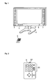
- Fig. 1 is a schematic perspective view to show an appearance structure of a thin type television device according to one embodiment of the present invention.
- Fig. 2 is a schematic diagram to show a structure of a remote controller for the thin type television device shown in Fig. 1 .
- Fig. 3 is a block diagram to show a structure of a swivel mechanism for the thin type television device shown in Fig. 1 .
- Fig. 4 is a block diagram to show a structure of a power voltage supply circuit for the swivel mechanism shown in Fig. 3 .
- Fig. 5 is a timing chart to show a relation between transition of a control signal from the remote controller and transition of voltage value which is output from the power voltage supply circuit.
- Fig. 6 is a block diagram to show another structure of the swivel mechanism for the thin type television device shown in Fig. 1 .
- Fig. 7 is a timing chart to show another relation between transition of a control signal from the remote controller and transition of voltage value which is output from the power voltage supply circuit shown in Fig. 4 .
- Fig. 8 is a block diagram to show another structure of the swivel mechanism for the thin type television device shown in Fig. 1 .
- FIG. 1 is a schematic perspective view to show an appearance structure of a thin type television device according to the present embodiment.
- Fig. 3 is a block diagram to show a structure of a swivel mechanism for the thin type television device shown in Fig. 1 .
- the thin type television device is provided with a display portion 1 which is a screen to reproduce and output an image, a supporting portion 2 which is connected to a center of bottom side of a back surface which is opposite side of the screen of the display portion 1, a driving portion 3 which is connected with the supporting portion 2 and includes an axis to rotate in horizontal direction, and a pedestal 4 on which the driving portion 3 is set as shown in Fig. 1 . That is, the driving portion 3 whose axis direction is perpendicular to the horizontal direction is set in order to locate at center portion on the pedestal 4, and the supporting portion 2 is formed on the driving portion 3 at a position that is opposite to the pedestal 4. Further, the thin type television device can be supported not to fall down on the pedestal 4 whose setting area is wide by connecting the supporting portion 2 to the back surface of the display portion 1.
- an axis to rotate in the horizontal direction a motor to rotate the axis, and a power transmission mechanism such as gears and the like to transmit a rotating force from the motor, are arranged and by these elements the swivel mechanism is composed of. That is, the display portion 1 can be rotated in the horizontal direction by an operation of the swivel mechanism that is set up in the driving portion 3. At this point, it is no problem that a tilting mechanism that makes the display portion 1 in a direction which is substantially perpendicular to the horizontal direction (tilting direction), is also provided in the driving portion 3.
- the thin type television device which is structured as above described is provided with an infrared light receiving portion 6 to receive infrared signal from a remote controller 5 in observed side where the screen of the display portion 1 is arranged in order that it is controlled by the remote controller 5 which performs instructions of operations by transmitting the infrared signal.
- a microcomputer which is set up in the thin type television device recognizes content of the instruction of operation that is included in the infrared signal which is output from the remote controller 5.
- the remote controller 5 is equipped with channel buttons 51 to select channel to be received, driving instruction buttons 52 to drive the display portion1 in the horizontal direction or the tilting direction, and an infrared transmitting portion 53 to transmit the infrared signal that corresponds to the button which is pushed on as shown in Fig. 2 .
- the driving portion 3 is operated such that the display portion 1 is driven in a direction which corresponds one of the driving instruction buttons 52 when it continues to be pushed on.
- the swivel mechanism shown in Fig. 3 is equipped with a signal converting portion 10 which performs demodulation and signal conversion of a signal from the infrared light receiving portion 6 that receives the infrared signal from the remote controller 5, a microcomputer portion 11 which analyses control signals from the signal converting portion 10, a motor driving IC 12 which is controlled by the microcomputer portion 11, a motor 13 which is driven by the motor driving IC 12, and a power voltage supply circuit 14 which supplies power voltage to the motor driving IC 12.
- a signal converting portion 10 which performs demodulation and signal conversion of a signal from the infrared light receiving portion 6 that receives the infrared signal from the remote controller 5
- a microcomputer portion 11 which analyses control signals from the signal converting portion 10
- a motor driving IC 12 which is controlled by the microcomputer portion 11
- a motor 13 which is driven by the motor driving IC 12
- a power voltage supply circuit 14 which supplies power voltage to the motor driving IC 12.
- a forward rotation control signal which makes the motor 13 forward rotation and a reverse rotation control signal which makes the motor 13 reverse rotation are output from the microcomputer portion 11 to the motor driving IC 12.
- the swivel mechanism of the driving portion 3 operates to rotate the display portion 1 in the horizontal direction because of operation of the motor 13 controlled by the motor driving IC 12 to which the forward rotation control signal and the reverse rotation control signal are input.
- the motor driving IC 12 is equipped with an inverter circuit (not shown) which is connected to a motor coil of the motor 13, and the forward rotation and the reverse rotation of the motor 13 is set by input of the forward rotation control signal and the reverse rotation control signal to a control terminal of a transistor switch of which the inverter circuit (not shown) is composed.
- the motor driving IC 12 also equipped with a ground terminal (reference mark GND in Fig. 3 ) which earths the inverter circuit (not shown) and voltage supply terminal (reference mark +B in Fig. 3 ) to which the power voltage is supplied.
- the inverter circuit (not shown) is biased by that the ground terminal is earthed and voltage which is output from the power voltage supply circuit 14 is supplied to the voltage supply terminal. Further, value of the output voltage from the power voltage supply circuit 14 is switched by a control signal from the microcomputer portion 11 and the output voltage is supplied to the voltage supply terminal of the motor driving IC 12.
- Torque of the motor 13 is varied by the value of the voltage which is supplied to the voltage supply terminal of the motor driving IC 12. That is, when the output voltage from the power voltage supply circuit 14 is higher, the torque of the motor 13 becomes larger.
- the power voltage supply circuit 14 is equipped with an NPN transistor T1 whose base to which the control signal from the microcomputer portion 11 is input via a resistor R1 and whose emitter is earthed, a zener diode D1 whose anode is connected to a collector of the transistor T1, a zener diode D2 whose cathode is connected to a cathode of the zener diode D1 and whose anode is earthed, an NPN transistor T2 whose base is connected to cathodes of the zener diodes D1 and D2 and whose collector is supplied with voltage VDD, and a resistor R2 which is connected between the base and the collector of the transistor T2.
- zener voltage of the zener diode D1 is set so as to be V1/2 (for example, 6V) when zener voltage of the zener diode D2 is V1 (for example, 12 V).
- the zener voltage V1 of the zener diode D2 is supplied to the voltage supply terminal of the motor driving IC 12 via the transistor T2 which works as a clamp.
- the zener voltage V1/2 of the zener diode D1 is supplied to the voltage supply terminal of the motor driving IC 12 via the transistor T2 which works as the clamp.
- the zener voltage of the zener diode D1 is set in V1/2, however, it is no problem that the value is different from V1/2 as far as it is lower than the zener voltage V1 of the zener diode D2.
- the device recognizes the forward rotation or the reverse rotation of the motor 13 is instructed by analyzing the infrared signal from the remote controller 5 using the microcomputer portion 11 as shown in Fig. 5 . Then, the forward rotation control signal or the reverse rotation control signal to drive the motor 13 is output from the microcomputer portion 11 to the motor driving IC 12.
- the transistor T1 becomes ON in the power voltage supply circuit 14 by input of the control signal to be high from the microcomputer portion 11, the zener voltage V1/2 of the zener diode D1 is input to the voltage supply terminal of the motor driving IC 12 by operation of the zener diode D1.
- the motor 13 performs the forward rotation or the reverse rotation with low torque and the display portion 1 is rotated in right or left in the horizontal direction.
- the operating voltage and the torque of the motor 13 are varied in stepwise by changing voltage value which is supplied to the voltage supply terminal of the motor driving IC 12.
- the motor driving IC 12 is equipped with a control terminal (reference mark CNT in Fig. 6 ) to switch the operating voltage which changes the torque of the motor 13 from the motor driving IC12, value of control signal to this control terminal is switched to output by the microcomputer portion 11.
- DAC circuit 15 which converts the digital signal that is output from the microcomputer portion11 into the analog signal, is set up. It is no problem that this DAC circuit 15 is a DAC circuit that converts the digital signal which is parallel signal from the microcomputer portion 11 into the analog signal or the DAC circuit that converts the digital signal which is serial signal from the microcomputer portion 11 into the analog signal.
- the voltage value which is input to the voltage supply terminal of the motor driving IC 12 is switched using two voltage values by controlling actions of the two zener diodes D1, D2 in the power voltage supply circuit 14.
- values of the control signal which are input to the control terminal of the motor driving IC 12 are switched in a plurality of steps as a structure shown in Fig. 6 , as far as magnitude of the torque of the motor 13 are switched in a plurality of steps by changing the operating voltage of the motor driving IC 12 in a plurality of steps.
- the operating voltage of the motor driving IC 12 are switched in a plurality of steps as described above, it is preferable that the operating voltage of the motor 13 are raised higher in sequential for every prescribed time length T by the motor driving IC 12 when the infrared signal from the remote controller 5 is received as shown in Fig. 7 . Then, operation of the motor driving IC 12 is stopped to terminate driving of the motor 13 when the infrared signal from the remote controller 5 becomes not input.
- a switch SW is connected to the voltage supply terminal of the motor driving IC 12 as shown in Fig. 8 , and when the microcomputer portion 11 confirms input of the infrared signal from the remote controller 5, the switch SW is turned ON by the microcomputer portion 11, and inversely, when the microcomputer portion 11 does not confirm input of the infrared signal from the remote controller 5, the switch SW is turned OFF by the microcomputer portion 11.
- the infrared signal to instruct driving of the driving portion 3 is continued to output while the button is pushed on.
- a structure is employed where output of the infrared signal is started at a first push down, and output of the infrared signal is terminated at a second push down.
- an infrared signal to instruct starting of driving of the driving portion 3 and an infrared signal to instruct stopping of driving of the driving portion 3 are output when driving and stopping of the driving portion 3 are instructed by operation of the driving instruction button 52.
- the present invention can be applied not only to the thin type television device that is explained in the embodiments but also to the thin type display device which includes display devices to reproduce image of computer or the like. Further, the present invention can be applied to the thin type display device which utilizes various methods such as a liquid crystal method, a plasma method, a rear projection method, a thin type Braun tube method, an Organic Electro-Luminescence method, a Surface-conduction Electron-emitter method, or the like as the thin type display device. Further in the above described embodiment, a structure is employed in which the device is driven by the remote controller 5. However, it is no problem that an operating portion is set up in the main body of the thin type display device, and selecting channel operation or display portion 1 driving operation by the driving portion 3 is instructed using operation of the operating portion.
Landscapes
- Engineering & Computer Science (AREA)
- General Engineering & Computer Science (AREA)
- Mechanical Engineering (AREA)
- Multimedia (AREA)
- Signal Processing (AREA)
- Devices For Indicating Variable Information By Combining Individual Elements (AREA)
- Control Of El Displays (AREA)
Applications Claiming Priority (1)
| Application Number | Priority Date | Filing Date | Title |
|---|---|---|---|
| JP2007015832A JP2008182620A (ja) | 2007-01-26 | 2007-01-26 | 薄型ディスプレイ装置 |
Publications (2)
| Publication Number | Publication Date |
|---|---|
| EP1950880A2 true EP1950880A2 (de) | 2008-07-30 |
| EP1950880A3 EP1950880A3 (de) | 2014-09-24 |
Family
ID=39402713
Family Applications (1)
| Application Number | Title | Priority Date | Filing Date |
|---|---|---|---|
| EP08001316.2A Withdrawn EP1950880A3 (de) | 2007-01-26 | 2008-01-24 | Dünne Anzeigevorrichtung |
Country Status (3)
| Country | Link |
|---|---|
| US (1) | US8179481B2 (de) |
| EP (1) | EP1950880A3 (de) |
| JP (1) | JP2008182620A (de) |
Families Citing this family (2)
| Publication number | Priority date | Publication date | Assignee | Title |
|---|---|---|---|---|
| TWM348883U (en) * | 2008-09-10 | 2009-01-11 | Amtran Technology Co Ltd | Electronic device |
| KR20170054866A (ko) * | 2015-11-10 | 2017-05-18 | 삼성전자주식회사 | 디스플레이 장치 및 그 제어 방법 |
Citations (4)
| Publication number | Priority date | Publication date | Assignee | Title |
|---|---|---|---|---|
| JPS63124775U (de) | 1987-02-04 | 1988-08-15 | ||
| JPH0342186U (de) | 1989-04-28 | 1991-04-22 | ||
| JPH0461575A (ja) | 1990-06-29 | 1992-02-27 | Nec Home Electron Ltd | ディスプレイ回転機構 |
| JP2004304679A (ja) | 2003-04-01 | 2004-10-28 | Matoba Denki Seisakusho:Kk | ディスプレイ用電動回転機構 |
Family Cites Families (3)
| Publication number | Priority date | Publication date | Assignee | Title |
|---|---|---|---|---|
| US4710686A (en) * | 1986-08-04 | 1987-12-01 | Guzik Technical Enterprises | Method and apparatus for control of current in a motor winding |
| KR100279633B1 (ko) * | 1998-12-08 | 2001-02-01 | 구자홍 | 2축 동력회전장치와 그 제어방법 |
| CN1862434A (zh) * | 2005-05-09 | 2006-11-15 | 华硕电脑股份有限公司 | 影像显示系统及其控制旋转角度的方法 |
-
2007
- 2007-01-26 JP JP2007015832A patent/JP2008182620A/ja active Pending
-
2008
- 2008-01-24 EP EP08001316.2A patent/EP1950880A3/de not_active Withdrawn
- 2008-01-25 US US12/010,547 patent/US8179481B2/en not_active Expired - Fee Related
Patent Citations (4)
| Publication number | Priority date | Publication date | Assignee | Title |
|---|---|---|---|---|
| JPS63124775U (de) | 1987-02-04 | 1988-08-15 | ||
| JPH0342186U (de) | 1989-04-28 | 1991-04-22 | ||
| JPH0461575A (ja) | 1990-06-29 | 1992-02-27 | Nec Home Electron Ltd | ディスプレイ回転機構 |
| JP2004304679A (ja) | 2003-04-01 | 2004-10-28 | Matoba Denki Seisakusho:Kk | ディスプレイ用電動回転機構 |
Also Published As
| Publication number | Publication date |
|---|---|
| US20080180582A1 (en) | 2008-07-31 |
| JP2008182620A (ja) | 2008-08-07 |
| US8179481B2 (en) | 2012-05-15 |
| EP1950880A3 (de) | 2014-09-24 |
Similar Documents
| Publication | Publication Date | Title |
|---|---|---|
| JP3559664B2 (ja) | 雲台装置 | |
| US7571038B2 (en) | In-vehicle multimedia system | |
| US8120714B2 (en) | Flat display device | |
| EP3166097A1 (de) | Anzeigevorrichtung und steuerungsverfahren dafür | |
| KR100433396B1 (ko) | 온 스크린 디스플레이 장치를 구비한 전자기기의 기능변경장치 및 방법 | |
| EP1774944B1 (de) | Rollstuhlsteuerungsanzeige, insbesondere mit Infrarotfähigkeit, Rollstuhl mit einer Steuerungsanzeige und Verfahren zum Aufbau einer Rollstuhlsteuerung | |
| US8179481B2 (en) | Thin type display device | |
| JP3975851B2 (ja) | 携帯端末装置 | |
| GB2276261A (en) | Input apparatus | |
| JP2006079407A (ja) | 入力装置及びこれを用いた入力ユニット | |
| JP2016120846A (ja) | 車両シート制御装置 | |
| US12064835B2 (en) | Operating panel for a welding device | |
| KR100226109B1 (ko) | 단일 버튼인 리모트 컨트롤러를 이용하여 텔레비전을 제어하는 방법 및 이를 수행하기 위한 장치. | |
| JP3144251B2 (ja) | テレビジョン受像機 | |
| JPH09274826A (ja) | 車両用多機能スイッチ装置 | |
| KR100662866B1 (ko) | 온 스크린 디스플레이 장치를 구비한 전자기기의 기능변경장치 및 방법 | |
| KR100219944B1 (ko) | 화상표시시스템의 부화면위치제어장치 | |
| JP2003340151A (ja) | 操作装置および同装置の信号出力調整方法 | |
| JP2004325748A (ja) | 電気光学装置及び電子機器 | |
| KR20060071118A (ko) | 원버튼 입력 방식의 티브이 | |
| KR0162748B1 (ko) | 제어항목표시/선택방식의 리모콘과 그 제어방법 | |
| KR19980057253A (ko) | 리모콘의 신호방향표시장치 | |
| JP3409332B2 (ja) | 表示装置 | |
| JP2003174570A (ja) | リモコン送信機 | |
| JP2008288914A (ja) | リモコン装置 |
Legal Events
| Date | Code | Title | Description |
|---|---|---|---|
| PUAI | Public reference made under article 153(3) epc to a published international application that has entered the european phase |
Free format text: ORIGINAL CODE: 0009012 |
|
| AK | Designated contracting states |
Kind code of ref document: A2 Designated state(s): AT BE BG CH CY CZ DE DK EE ES FI FR GB GR HR HU IE IS IT LI LT LU LV MC MT NL NO PL PT RO SE SI SK TR |
|
| AX | Request for extension of the european patent |
Extension state: AL BA MK RS |
|
| PUAL | Search report despatched |
Free format text: ORIGINAL CODE: 0009013 |
|
| AK | Designated contracting states |
Kind code of ref document: A3 Designated state(s): AT BE BG CH CY CZ DE DK EE ES FI FR GB GR HR HU IE IS IT LI LT LU LV MC MT NL NO PL PT RO SE SI SK TR |
|
| AX | Request for extension of the european patent |
Extension state: AL BA MK RS |
|
| RIC1 | Information provided on ipc code assigned before grant |
Ipc: F16M 11/18 20060101ALI20140815BHEP Ipc: F16M 11/08 20060101ALI20140815BHEP Ipc: H02P 7/00 20060101AFI20140815BHEP |
|
| STAA | Information on the status of an ep patent application or granted ep patent |
Free format text: STATUS: THE APPLICATION HAS BEEN WITHDRAWN |
|
| 18W | Application withdrawn |
Effective date: 20150120 |