EP1950552B1 - Procédé et système de mise en oeuvre d'excitation modulée spatialement pour la caractérisation de particule avec une sensibilité améliorée - Google Patents
Procédé et système de mise en oeuvre d'excitation modulée spatialement pour la caractérisation de particule avec une sensibilité améliorée Download PDFInfo
- Publication number
- EP1950552B1 EP1950552B1 EP08150482.1A EP08150482A EP1950552B1 EP 1950552 B1 EP1950552 B1 EP 1950552B1 EP 08150482 A EP08150482 A EP 08150482A EP 1950552 B1 EP1950552 B1 EP 1950552B1
- Authority
- EP
- European Patent Office
- Prior art keywords
- particle
- signal
- excitation region
- excitation
- particles
- Prior art date
- Legal status (The legal status is an assumption and is not a legal conclusion. Google has not performed a legal analysis and makes no representation as to the accuracy of the status listed.)
- Ceased
Links
Images


Classifications
-
- G—PHYSICS
- G01—MEASURING; TESTING
- G01N—INVESTIGATING OR ANALYSING MATERIALS BY DETERMINING THEIR CHEMICAL OR PHYSICAL PROPERTIES
- G01N21/00—Investigating or analysing materials by the use of optical means, i.e. using sub-millimetre waves, infrared, visible or ultraviolet light
- G01N21/62—Systems in which the material investigated is excited whereby it emits light or causes a change in wavelength of the incident light
- G01N21/63—Systems in which the material investigated is excited whereby it emits light or causes a change in wavelength of the incident light optically excited
- G01N21/64—Fluorescence; Phosphorescence
- G01N21/6486—Measuring fluorescence of biological material, e.g. DNA, RNA, cells
-
- G—PHYSICS
- G01—MEASURING; TESTING
- G01N—INVESTIGATING OR ANALYSING MATERIALS BY DETERMINING THEIR CHEMICAL OR PHYSICAL PROPERTIES
- G01N15/00—Investigating characteristics of particles; Investigating permeability, pore-volume or surface-area of porous materials
- G01N15/10—Investigating individual particles
- G01N15/14—Optical investigation techniques, e.g. flow cytometry
- G01N15/1468—Optical investigation techniques, e.g. flow cytometry with spatial resolution of the texture or inner structure of the particle
- G01N15/147—Optical investigation techniques, e.g. flow cytometry with spatial resolution of the texture or inner structure of the particle the analysis being performed on a sample stream
-
- G—PHYSICS
- G01—MEASURING; TESTING
- G01N—INVESTIGATING OR ANALYSING MATERIALS BY DETERMINING THEIR CHEMICAL OR PHYSICAL PROPERTIES
- G01N15/00—Investigating characteristics of particles; Investigating permeability, pore-volume or surface-area of porous materials
- G01N15/10—Investigating individual particles
- G01N15/14—Optical investigation techniques, e.g. flow cytometry
- G01N15/1425—Optical investigation techniques, e.g. flow cytometry using an analyser being characterised by its control arrangement
- G01N15/1427—Optical investigation techniques, e.g. flow cytometry using an analyser being characterised by its control arrangement with the synchronisation of components, a time gate for operation of components, or suppression of particle coincidences
-
- G—PHYSICS
- G01—MEASURING; TESTING
- G01N—INVESTIGATING OR ANALYSING MATERIALS BY DETERMINING THEIR CHEMICAL OR PHYSICAL PROPERTIES
- G01N15/00—Investigating characteristics of particles; Investigating permeability, pore-volume or surface-area of porous materials
- G01N15/10—Investigating individual particles
- G01N15/14—Optical investigation techniques, e.g. flow cytometry
- G01N15/1434—Optical arrangements
- G01N2015/1447—Spatial selection
-
- G—PHYSICS
- G01—MEASURING; TESTING
- G01N—INVESTIGATING OR ANALYSING MATERIALS BY DETERMINING THEIR CHEMICAL OR PHYSICAL PROPERTIES
- G01N15/00—Investigating characteristics of particles; Investigating permeability, pore-volume or surface-area of porous materials
- G01N15/10—Investigating individual particles
- G01N15/14—Optical investigation techniques, e.g. flow cytometry
- G01N15/1434—Optical arrangements
- G01N2015/1454—Optical arrangements using phase shift or interference, e.g. for improving contrast
-
- Y—GENERAL TAGGING OF NEW TECHNOLOGICAL DEVELOPMENTS; GENERAL TAGGING OF CROSS-SECTIONAL TECHNOLOGIES SPANNING OVER SEVERAL SECTIONS OF THE IPC; TECHNICAL SUBJECTS COVERED BY FORMER USPC CROSS-REFERENCE ART COLLECTIONS [XRACs] AND DIGESTS
- Y10—TECHNICAL SUBJECTS COVERED BY FORMER USPC
- Y10T—TECHNICAL SUBJECTS COVERED BY FORMER US CLASSIFICATION
- Y10T436/00—Chemistry: analytical and immunological testing
- Y10T436/14—Heterocyclic carbon compound [i.e., O, S, N, Se, Te, as only ring hetero atom]
- Y10T436/142222—Hetero-O [e.g., ascorbic acid, etc.]
- Y10T436/143333—Saccharide [e.g., DNA, etc.]
-
- Y—GENERAL TAGGING OF NEW TECHNOLOGICAL DEVELOPMENTS; GENERAL TAGGING OF CROSS-SECTIONAL TECHNOLOGIES SPANNING OVER SEVERAL SECTIONS OF THE IPC; TECHNICAL SUBJECTS COVERED BY FORMER USPC CROSS-REFERENCE ART COLLECTIONS [XRACs] AND DIGESTS
- Y10—TECHNICAL SUBJECTS COVERED BY FORMER USPC
- Y10T—TECHNICAL SUBJECTS COVERED BY FORMER US CLASSIFICATION
- Y10T436/00—Chemistry: analytical and immunological testing
- Y10T436/17—Nitrogen containing
Definitions
- Methods for particle characterization (which generally relates to detection as well as other useful characterizations such as location/position determination, particle counting and cell sorting) often suffer from a low signal-to-noise ratio (SNR), since the signal obtained from the particle (in general: a small object) is typically weak in comparison to the background. This is particularly true in connection with optical methods of particle characterization.
- SNR signal-to-noise ratio
- the low signal-to-noise ratio is also particularly noteworthy in cases of detection of individual particles such as a cell, an aerosol, a molecule, a subvolume of liquid which differs from the surrounding liquid or emulsion, or a piece of DNA with dyes or tags at selection positions.
- DNA sequencing is accomplished by splitting a DNA strand into small pieces, separating the pieces with electrophoresis and then elaborately reconstructing the DNA sequence.
- An alternative process has recently been developed. In this alternative process, certain base sequences are tagged with fluorescent dyes. After stretching (or “linearizing") the molecule, the DNA strand is moved through a microfluidic channel at a constant speed. A special fluorescence reader with a high spatial resolution (approx. 1 ⁇ m) is used to record the positions of the fluorescent dyes or tags. As a result, an "optical bar code" of the DNA containing the position of the tags is recorded. Therefore, the DNA sequence may be identified.
- Typical distance between the tags along the DNA is several ⁇ m. Consequently, the required spatial resolution is one ⁇ m or better.
- this concept is demonstrated by using a con-focal microscope, which allows for exciting and also detecting the fluorescence within a very small volume ( ⁇ 1 ⁇ m3).
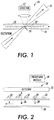
- FIG. 1 schematically illustrates a conventional approach for spatially resolved fluorescence excitation.
- a system 10 includes a detector 12, a channel 14 and an excitation light 16. A small volume within the channel 14 is excited. Light is collected from the excited volume. DNA strings 20 with tagged portions 22 run through an excitation area 24 of the channel 14. The positions of the tags are calculated using a time dependent detector signal.
- Patent application WO2004033059 discloses a method and apparatus to characterise particles flowing through a spatially modulated optical excitation region
- Patent document US4596036 discloses a method and apparatus to characterise particles flowing through an interference fringe pattern.
- the invention consists of a method and an apparatus to characterise particles as defined by the appended claims.
- This patent application describes a method and a system to improve the signal-to-noise ratio during particle characterization by implementing a phase sensitive technique which allows for clearly distinguishing between the signals from the particle and the background.
- the method is based on the deliberate introduction of controlled relative movement between the particle and the environment.
- the combination of, for example, the moving particle and a conditioned environment results in a time modulated signal.
- a monitored response comprises a noisy background signal and the modulated signal, with a well defined time dependence attributable to the particle.
- Both hardware and software solutions can be applied to extract the signal attributed to the particle.
- the signal attributed to the particle can then be used in characterizing the particle for a variety of different applications, including detection, location/position determination, and cell sorting.
- Various techniques may be employed to accomplish these characterizations. It should be noted, however, that one technique for characterization, i.e., determination of particle positions and distances, is described in U.S. Application Serial No. 11/698338 , entitled “Method and System for Evaluation of Signals Received from Spatially Modulated Excitation and Emission to Accurately Determine Particle Positions and Distances,” filed on even date herewith, and may be advantageously implemented along with the presently described embodiments.
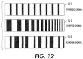
- the contemplated signal can have any shape as a function of time. It is not necessarily periodic. Even a signal modulated randomly is useful, as long as the structure of the signal is known. In this regard, the structure may be known but the signal may not follow an analytic regularity. So, the time periods defining "on” and “off” states for the particle will have a random length. Even where the time dependence of the signal is built into the system, the time dependence of the system can be varied, as long as it is predictable or known.
- signal 12-1 is a periodic signal.
- Signal 12-2 is a chirped signal, e.g., a signal that has a linearly increasing frequency. Also shown is a random signal 12-3. It should be appreciated that these signals (as well as others) may be used in connection with the presently described embodiments to achieve the objectives of the presently described embodiments.
- the presently described embodiments are described for a variety of cases including: (1) a collection of individual moving particles (2) a linearized DNA strand in which the objects of interest are distributed and fixed along the length of the strand i.e., commonly termed DNA sequencing, and (3) a collection of particles potentially fixed on a surface (providing a need, in some applications, for a two-dimensional analysis).
- the particles being detected may include cells, aerosols, DNA material pieces of DNA with dyes at selected positions, subvolumes in a liquid which differs from the surrounding liquid or emulsion, droplets, other small volumes of fluid, bubbles, single molecules, agglomerated molecules, molecule clusters, biological cells, viruses, bacteria, proteins, microparticles, nanoparticles, and emulsions.
- a droplet or small volume of fluid may, for example, include atoms, molecules or other particles that affect refractive index, absorption, or other optical characteristics.
- the object could be conveyed in a fluid, such as a liquid, gas, or aerosol, in which case the object may be referred to as being "carried by the fluid.”
- a channel may be defined in a variety of manners to include not only ones defined by walls, but also ones defined by the flow of particles in, for example, an aerosol stream or the like.
- light emission from these particles may result from a variety of sources including fluorescence excitation, elastic and inelastic light scattering, chemo-luminescence or other types of light scattering and reflection techniques. Still further, the light used in these implementations may include a variety of different types of lighting including, ultraviolet, VIS, infrared, near infrared, etc.
- the environments in which this particle characterization process is implemented are environments wherein there is a spatially modulated excitation of the particles or in some examples which are not part of the present invention, a modulation of an emitted light from particles over a detection region.
- the particles may emit a homogeneous excitation that is filtered using, for example, a shadow mask or other optics, which leads to a spatial modulation of the emitted light.
- Figures 2-14 generally relate to optical cases while Figure 15 relates to an example non-optical case.
- a channel 34 is provided with optical elements 32 for modulating emitted light within a detection region.
- the optical elements 32 may take a variety of forms such as lenses, masks or filters.
- a detector 31 for detecting the emitted light from the optical elements 32 as a function of time. It should be understood that the detector 31 (as well as other detectors noted herein) may take a variety of forms including photo-diodes, avalanche photo-diodes, photo-multiplier tubes, etc. It should also be appreciated that the detector 31 and optical elements 32 may be combined in a single element or system.
- Light may be emitted from particles such as particle 36 and particle 38 that are traveling down the channel 34. It should be understood that the light emission from the particle may result from the various phenomenon described above. It should also be understood that the relative movement between the particles 36 and 38 and the optical element system 32, or output modulator, create the modulation desired to be able to appropriately analyze the particles 36 and 38.
- the spatially modulated optics create a time modulated signal in the detector 31. This signal, which as noted may take a variety of predictable forms, may be analyzed using the processing module 39 for purposes of characterizing the particles.
- the signal generated as a function of time may take a variety of forms, e.g., periodic, chirped, random...etc., as a function of a variety of environmental factors.
- the optics may take a form that coincides with the type of signal. So, the optical element structure may resemble that of the signal examples of Figure 12 .
- the relative movement may be created by way of the particle moving, the detector/optical elements moving along, for example, the channel or by way of movement of both of these elements. It should be further understood that movement of both of the elements may, in one form, result in movement of each element at different velocities.
- the system 40 includes a channel 42 that is provided with regions 44 where particles, such as particles 46 and 48, are caused to emit light. Regions 44, as shown, create a modulated excitation area that can be achieved by various methods. These methods include use of shadow masking, use of lens arrays Relative movement between the particle and the excitation area or pattern can be achieved by moving the excitation pattern or by moving both the particle and the excitation pattern. It should be appreciated that movement of both, in one form, would result in movement of each at different speeds.
- the spatially modulated optics create a time modulated signal in the detector 41. This signal, which as noted may take a variety of predictable forms, may be analyzed using the processing module 49 for purposes of characterizing the particles.
- System 50 includes a channel 52 and an anti-resonant wave guide 54.
- the anti-resonant wave guide provides homogeneous illumination of the channel as the particle travels therethrough.
- Modulation can be created by mirrors 56 which can be suitably placed inside or outside the channel.
- the spatially modulated optics create a time modulated signal in the detector 51. This signal, which as noted may take a variety of predictable forms, may be analyzed using the processing module 59 for purposes of characterizing the particles.
- the invention provides for a characterization of particles traveling through other types of medium (e.g., liquid) that is improved by way of modulation.
- the modulation occurs by way of modulated excitation of the particles.
- it is the relative movement of the system elements that provides the modulated effect.
- FIG. 11 another example which is not part of the present invention, is illustrated.
- a system 300 positioned near a channel 302 in which a particle 304 is traveling.
- the particle 304 is detected by a detector 306 having an optical element 308 positioned thereon operative to produce a spatial pattern.
- the detection of the particle is facilitated by optics 310, which may take a variety of forms including a lens or lens system.
- the particle lies in an object plane 320 while an image plane 322 is associated with the detector 306 and optical element 308.
- the particle size, pattern size and spatial resolution are essentially de-coupled.
- the optics 310 serve to magnify (or de-magnify) the particle 304 and conduct the detecting at a location remote from the particle 304.
- light originating from the particle 304 is modulated in the image plane 322.
- the detector 306 is then able to detect the light from the particle 304 in the channel 302 without being positioned on the channel 302.
- the optical element 308 should be in or near the image plane 322 of the optics 310. In this way, the "optical distance" between the particle 304 and the optical element 308 is minimized.
- the detector itself can contain optics as well as introduce additional magnification or de-magnification.
- the size of the detector is a factor in the sampling rate of the system. In some cases it might therefore be preferable to de-magnify the channel on a small and faster detector to gain increased sampling rate.
- the optical element may be positioned on the channel itself. If so, the distance between the detector and the optical element would be determined by the channel dimensions.
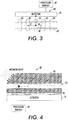
- a more specific implementation of the presently described embodiments relates to DNA sequencing.
- a system 100 according to the presently described embodiments is shown.
- the system includes a detector 102, a fluid channel 104 and excitation light 106 having a spatially modulated excitation pattern 108 therewithin.
- the pattern 108 aligns with the channel 104 to create a detection region or area 105.
- the system 100 allows for conveyance of, for example, a DNA string 110 having a backbone portion 112 and fluorescent tags, or particles, 114 embedded therein.
- the interference pattern 108 is generated by an energy source such as a laser source and has a submicron periodicity perpendicular to particle flow. It should be appreciated that other angles might also be used.
- the fluorescent emission is modulated according to the speed of the fluorescent particle or tag 114 and the periodicity of the stripe pattern 108.
- the signal detector 102 which records the emission over at least one stripe can be used.
- the detected signal is recorded with a fast detector read-out in order to capture the "blinking" of the fluorescent particle(s) or tags 114 while they are moving through the detection area 105 and, consequently, the excitation pattern 108.
- a processing module 109 may be implemented to analyze the signal for purposes of particle characterization.
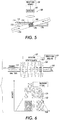
- the presently described embodiments enable fluorescence detection with high signal-to-noise ratio and high spatial resolution, as discussed in the following, without the need of expensive and bulky optics.
- the DNA backbone 112 is typically labeled with one type of fluorophore and specific portions of the linearized molecule are labeled with a second type of fluorophore, that is, fluorescent tags 114.
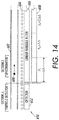
- Figure 6 illustrates the detection scheme according to the presently described embodiments in more detail. As shown, the fluorescence backbone signal 120 first increases in a step-like function when the uniformly labeled DNA backbone 112 moves into the detection area 105. Additionally, the backbone signal 120 is superimposed with a sinusoidal signal 122 when one of the tags 114 moves through the excitation pattern 108. This results in a detected signal 126.
- Backbone portions 112 and tagged portions 114 are usually labeled with fluorophores emitting at different wavelength bands.
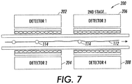
- Appropriate filters ensure that only fluorescence originating from the tags enters detector 202 whereas detector 204 receives light only from the backbone.
- Simple optical components can be incorporated to improve wavelength selectivity of the filters. For example, micro-lens arrays can collimate the fluorescent light.
- the filters can be designed such that they do not only transmit the first wavelength band of interest but also efficiently reflect the second wavelength band of interest onto the opposite detector in order to minimize fluorescent light loss.
- the system 200 of Figure 7 can also be used to measure the fluorescence from different fluorescence tags marking different portions of the DNA simultaneously.
- second stage detectors 206 and 208 may likewise be implemented to refine, for example, the DNA analysis that is being conducted. For example, to refine a DNA characterization, fluorescence from differently colored tags marking different portions of a DNA strand may be measured.
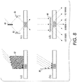
- Figure 8(d) which shows an embodiment of the present invention
- Figures 8(a)-(c) depict examples which are not part of the present invention.
- Stripes are usually generated by creating a standing wave in one dimension.
- a mirror 80 creates a standing wave in the channel direction.
- Different directions also may be used.
- the distance d between two adjacent interference maxima can be calculated as follows: d ⁇ 2 sin ⁇ ,
- a indicates the relative angle between the two interfering beams and ⁇ is the wavelength, with d varying between ⁇ /2 and infinity dependent upon ⁇ .
- the excitation pattern can be directed onto the channel "from outside” through the top or bottom surface or “in plane” from the side.
- the detection components are most probably attached from top and/or bottom it is favorable to use "in-plane” excitation in order to reduce the amount of excitation light that reach the detectors.
- FIG. 8(a)-(d) All of the interferometer techniques shown in Figure 8(a)-(d) can be realized in the microfluidic chamber by using waveguide structures and mirrors based on total internal reflection (TIR) on substrate/air interfaces.
- Figure 8(a) illustrates a prism interferometer.
- Figure 8(b) illustrates a Lloyd interferometer using the mirror 80.
- Figure 8(c) illustrates a Michelson interferometer using a beam splitter 84 and mirrors 86.
- a periodically moving stage e.g., a speaker or piezo element.
- This technique can also be applied to address stationary particles. This allows improvement in the sensitivity of the system by using a double modulation technique.
- Figure 8(d) illustrates a phase mask interferometer 88.
- a favorable approach is based on phase masks or transmission gratings, as shown in Figure 8(d) .
- Light scattered into the -1st order interferes with light scattered in +1st order.
- the gratings can be designed such that scattering into 0 and 2nd order is minimized. Most techniques shown in this section can be designed such that multiple-fluidic-channel excitation is feasible.
- Figure 10 illustrates another design for illuminating parallel channels which is based on phase masks, such as phase mask 90.
- the methods according to the presently described embodiments include, in at least one form, the basic undertakings of creating a spatially modulated environment, detecting light emitted from the excited particles in the environment, and generating a time modulated signal based on the detecting.
- the generated signal is used to determine positions of the excited particles, e.g. tags in the DNA strand.
- the system in one form, is provided with a processing module (e.g., processing modules 39, 49, 59 and 109) to allow for the generation of the spatially modulated signal and any subsequent processing such as determining the relative positions of particles.
- This processing module may be incorporated within the detector or implemented apart from the detector.
- the methods described herein may be implemented using a variety of hardware configurations and software techniques.
- the contemplated processing module may include software routines that will allow for signal generation and location determination.
- an excitation pattern is generated (at 502).
- the excitation may be homogeneous with a patterned output generated by a shadow mask or the like (e.g., a modulator).
- a patterned output generated by a shadow mask or the like (e.g., a modulator).
- relative movement between, for example, a fluorescing analyte and the excitation pattern is provided (at 504). Any emitted or scattered light as function of time is then detected (at 506).
- a spatially modulated signal based on the detecting is then generated (at 508).
- the spatially modulated signal can then be used, in one form, to determine the relative positions of fluorescing particles such as tags in a DNA strand.
- the modulated excitation not only ensures high spatial resolution but at the same time enables a method to increase the signal-to-noise ratio.
- Most sources which contribute to the background signal e.g., the backbone signal, fluorescence excited by scattered excitation, or all other DC-like sources
- an a periodic excitation pattern with a stripe width of 1 ⁇ m and a size of the tagged portion considerably less than the excitation stripe results in a transit time of approximately 70 ⁇ s per period. This results in a modulation of the fluorescence signal in the order of 10 kHz.
- the excitation source can be modulated with a higher frequency in order to separate fluorescence light from other background sources (e.g., room light). The frequency has to be chosen high enough to ensure that the light source is switched on and off several times while a tag is passing one interference fringe.
- a modulation frequency of 100kHz fulfills that criterion and is easily feasible. As much faster detectors are available, it is even possible to apply conventional lock-in or correlation techniques to sample more accurately at 100 kHz, e.g., by modulating the excitation light with 1 MHz in phase with a detector.
- the detector signal in order to determine the precise position of the tags on the DNA, the detector signal (no mater how obtained) is deconvoluted.
- the signal is recorded with a high sampling rate.
- the time information is thus converted to position information using the velocity of the DNA string.
- the velocity of the DNA string is extracted from the periodicity of the time dependent fluorescence signal or can be measured by other well known techniques.
- the analysis can be done, using a variety of signal processing algorithms including Fourier-Transformation analysis or Least-Square fitting techniques. Some of these techniques are described in greater detail in, for example, U.S. Application Serial No. 11/698338 , entitled "Method and System for Evaluation of Signals Received from Spatially Modulated Excitation and Emission to Accurately Determine Particle Positions and Distances", filed on even date herewith.
- a particle scanner 200 may be used to locate or localize a particle 202 using a two dimensional technique.
- the particle 202 may be within a fluid having particles suspended therein and housed on a slide that is positioned on the bed of the scanner 202.
- the scanner 200 includes a modulation pattern 204 and a modulation pattern 206.
- the modulation pattern 204 is moved relative to the particle 202 in a first direction 212 while the modulation pattern 206 is subsequently moved relative to the particle 202 in a second direction 210.
- the first and second directions are, in one form, substantially perpendicular to one another.
- the bed (or a fixture) of the scanner 200 may also be moved to generate the relative motion between the particle and the modulation pattern.
- the modulation pattern 204 and 206 are excitation patterns to excite the particle, or in an example which is not part of the present invention, they could be optical elements provided to modulate a constant light emission from the particle.
- the relative movement contemplated will result in detection of light and a corresponding modulated signal that will allow for the determination of the location of the particle. In this regard, the location of the particle may be determined at the position where both modulation patterns yield a suitable signal.
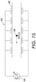
- an example which is not part of the present invention, of a non-optical method is one that utilizes electrical properties (such as capacitance, conductance or impedance) instead of light as a modulated output signal.
- a particle 400 may be moved down a channel 402 through an electrode array 404, instead of an optical array.
- the electrode array 404 is connected to a measurement device 406 and is set up to record the time dependent signal (e.g. capacitance or current) influenced by the moving particle and operates to achieve the objectives of the presently described embodiments described herein.
- Fluorescence spectroscopy Measuring the fluorescence spectra of particles which pass through the modulated excitation region with high signal-to-noise ratio by coupling the fluorescence light into a spectrometer.
- a particle 600 travels down a channel 602.
- a shadow mask 604 creates a modulation on each individual pixel of the detector 608.
- Each pixel of detector 608 records the signal at a particular wavelength over a subrange ⁇ determined by the linear variable filter 606. This system may be adjacent a particle detector system 610 having a detector 612.
- the detection system can also be scanned along a channel or carrier / chip.
- the particles of interest are fixed on the chip and, e.g., the absolute position of particles on the chip is determined.
- the concept can, for example, also be applied to fluorescence read-out of a bio-chip.
- Spatial modulations can be achieved in different manners.
- geometry may provide a basis for spatial modulation.
- a spatially modulated shadow mask e.g. interdigitated finger-type mask, a spatially modulated phase mask, a micro-lens array are used; in an example which is not part of the present invention a micromirror array may be used.
- spatial modulation may also be achieved using electric or magnetic fields.
- emitted fluorescence intensity can be affected by the modulated field.
- the density of the fluorescence object may be modulated by the field and the optical path can be affected by the field.
- spatially modulated acoustic field may also be used.
- emitted fluorescence intensity can be impacted by the modulated field.
- the density of the fluorescence object may be modulated by the field.
- the optical path can be affected by the field.
- Spatially modulated environment e.g. stationary molecular coatings
- Spatially modulated fluorescence quenching may also be useful.
- a spatially modulated micro-cavity which influences the emission properties of the moving object may likewise be applied to achieve objectives of the presently described embodiments.
- the location of a particle can be determined with high resolution by analyzing the time dependence of a generated signal. This is enabled by a spatially modulated excitation pattern (e.g., interference pattern) in combination with a relative movement between a particle and excitation pattern.
- a spatially modulated excitation pattern e.g., interference pattern
- the lower bound of the spatial resolution is determined by the feature size of an interference pattern which can be chosen much smaller that 1 ⁇ m.
- the feature size of an interference pattern which can be chosen much smaller that 1 ⁇ m.
- the analyzed signal is modulated with periodic excitation variation. Lock-in techniques or correlation techniques can be applied to significantly enhance the signal-to-noise ratio.
- the techniques can be integrated into a lab-on-a-chip platform and can be easily extended to parallel multi-fluidic-channel analysis.
- the feature size of the interference pattern determines the distance between two particles, which can be separated. Dependent upon the signal-to-noise ratio, the time coding of the signal, the relative speed of the particles and the pattern, the sampling rate of the detector, and the applied evaluation technique, it is feasible to achieve a particle separation better than the feature size of the interference pattern.
- reduced intensity of the excitation light reduces damage, e.g. on living cells or bleaching of dyes.
Landscapes
- Health & Medical Sciences (AREA)
- Chemical & Material Sciences (AREA)
- Life Sciences & Earth Sciences (AREA)
- Immunology (AREA)
- Pathology (AREA)
- General Physics & Mathematics (AREA)
- Physics & Mathematics (AREA)
- General Health & Medical Sciences (AREA)
- Analytical Chemistry (AREA)
- Biochemistry (AREA)
- Dispersion Chemistry (AREA)
- Biomedical Technology (AREA)
- Nuclear Medicine, Radiotherapy & Molecular Imaging (AREA)
- Engineering & Computer Science (AREA)
- Molecular Biology (AREA)
- Investigating, Analyzing Materials By Fluorescence Or Luminescence (AREA)
- Apparatus Associated With Microorganisms And Enzymes (AREA)
- Measuring Or Testing Involving Enzymes Or Micro-Organisms (AREA)
Claims (6)
- Procédé de caractérisation de particules, le procédé comprenant :la génération d'une région d'excitation optique spatialement modulée (44),la création d'un déplacement relatif entre une particule (46, 48) et la région d'excitation (44), la particule (46, 48) étant excitée lors d'une exposition à la région d'excitation (44) pour obtenir un signal modulé dans le temps qui est provoqué par une émission de lumière à partir de la particule (46, 48) ; etl'enregistrement du signal modulé ;dans lequel ladite création d'un déplacement relatif entre la particule (46, 48) et la région d'excitation (44) comprend le déplacement de ladite région d'excitation (44), caractérisé en ce que :
ladite région d'excitation (44) est générée par au moins l'un parmi un masque perforé, un masque de phase et un réseau de lentilles. - Procédé selon la revendication 1 dans lequel la région d'excitation (44) inclut un motif d'excitation.
- Procédé selon la revendication 1 comprenant en outre au moins l'un parmi la détermination d'un emplacement de la particule (46, 48) sur la base du signal, le comptage de particules (46, 48) sur la base du signal, et le tri de particules (46, 48) sur la base du signal.
- Procédé selon l'une quelconque des revendications précédentes, dans lequel ladite création du déplacement relatif entre la particule (46, 48) et la région d'excitation (44) comprend en outre le déplacement de la particule (46, 48) à l'intérieur d'un canal (42).
- Système (40) de caractérisation de particules comprenant :un moyen (88) pour générer une région d'excitation optique spatialement modulée (44),un moyen pour fournir un déplacement relatif entre une particule (46, 48) et la région d'excitation (44), la particule (46, 48) étant excitée lors d'une exposition à la région d'excitation (44) pour obtenir un signal modulé dans le temps qui est provoqué par une émission de lumière à partir de la particule ; etun moyen (41) pour enregistrer le signal modulé ;dans lequel ledit moyen pour fournir un déplacement relatif entre la particule (46, 48) et la région d'excitation modulée (44) comprend un moyen pour déplacer ladite région d'excitation spatialement modulée (44), caractérisé en ce que :
ledit moyen (88) pour générer ladite région d'excitation optique spatialement modulée (44) comprend au moins l'un parmi un masque perforé, un masque de phase et un réseau de lentilles. - Système selon la revendication 5, dans lequel le moyen pour fournir un déplacement relatif entre la particule et la région d'excitation spatialement modulée comprend en outre :un canal (42) ; etun moyen pour déplacer une particule (46, 48) à l'intérieur du canal (42).
Applications Claiming Priority (1)
| Application Number | Priority Date | Filing Date | Title |
|---|---|---|---|
| US11/698,409 US8821799B2 (en) | 2007-01-26 | 2007-01-26 | Method and system implementing spatially modulated excitation or emission for particle characterization with enhanced sensitivity |
Publications (3)
| Publication Number | Publication Date |
|---|---|
| EP1950552A2 EP1950552A2 (fr) | 2008-07-30 |
| EP1950552A3 EP1950552A3 (fr) | 2010-11-17 |
| EP1950552B1 true EP1950552B1 (fr) | 2021-01-20 |
Family
ID=39474016
Family Applications (1)
| Application Number | Title | Priority Date | Filing Date |
|---|---|---|---|
| EP08150482.1A Ceased EP1950552B1 (fr) | 2007-01-26 | 2008-01-22 | Procédé et système de mise en oeuvre d'excitation modulée spatialement pour la caractérisation de particule avec une sensibilité améliorée |
Country Status (3)
| Country | Link |
|---|---|
| US (2) | US8821799B2 (fr) |
| EP (1) | EP1950552B1 (fr) |
| JP (1) | JP5243052B2 (fr) |
Families Citing this family (75)
| Publication number | Priority date | Publication date | Assignee | Title |
|---|---|---|---|---|
| US8821799B2 (en) * | 2007-01-26 | 2014-09-02 | Palo Alto Research Center Incorporated | Method and system implementing spatially modulated excitation or emission for particle characterization with enhanced sensitivity |
| US9164037B2 (en) | 2007-01-26 | 2015-10-20 | Palo Alto Research Center Incorporated | Method and system for evaluation of signals received from spatially modulated excitation and emission to accurately determine particle positions and distances |
| US7502123B2 (en) * | 2007-02-05 | 2009-03-10 | Palo Alto Research Center Incorporated | Obtaining information from optical cavity output light |
| US7936463B2 (en) * | 2007-02-05 | 2011-05-03 | Palo Alto Research Center Incorporated | Containing analyte in optical cavity structures |
| US7554673B2 (en) | 2007-02-05 | 2009-06-30 | Palo Alto Research Center Incorporated | Obtaining information about analytes using optical cavity output light |
| US7545513B2 (en) * | 2007-02-05 | 2009-06-09 | Palo Alto Research Center Incorporated | Encoding optical cavity output light |
| US7817276B2 (en) * | 2007-02-05 | 2010-10-19 | Palo Alto Research Center Incorporated | Distinguishing objects |
| US7633629B2 (en) * | 2007-02-05 | 2009-12-15 | Palo Alto Research Center Incorporated | Tuning optical cavities |
| US8320983B2 (en) | 2007-12-17 | 2012-11-27 | Palo Alto Research Center Incorporated | Controlling transfer of objects affecting optical characteristics |
| US7701580B2 (en) | 2008-02-01 | 2010-04-20 | Palo Alto Research Center Incorporated | Transmitting/reflecting emanating light with time variation |
| JP5541764B2 (ja) * | 2008-01-30 | 2014-07-09 | パロ・アルト・リサーチ・センター・インコーポレーテッド | 物体検出に応答して情報を取得する装置及び方法 |
| US7817254B2 (en) * | 2008-01-30 | 2010-10-19 | Palo Alto Research Center Incorporated | Obtaining information from time variation of sensing results |
| US8263955B2 (en) * | 2008-12-18 | 2012-09-11 | Palo Alto Research Center Incorporated | Causing relative motion |
| EP2085762B1 (fr) | 2008-01-30 | 2018-07-04 | Palo Alto Research Center Incorporated | Transmission/réflexion de lumière d'émission avec une variation temporelle |
| US7894068B2 (en) * | 2008-02-04 | 2011-02-22 | Palo Alto Research Center Incorporated | Producing filters with combined transmission and/or reflection functions |
| US7763856B2 (en) * | 2008-01-31 | 2010-07-27 | Palo Alto Research Center Incorporated | Producing time variation in emanating light |
| EP2085797B1 (fr) * | 2008-01-30 | 2016-06-01 | Palo Alto Research Center Incorporated | Production de filtres avec des fonctions de transmission et/ou de réflexion combinées |
| US8153949B2 (en) * | 2008-12-18 | 2012-04-10 | Palo Alto Research Center Incorporated | Obtaining sensing results indicating time variation |
| EP2085761B1 (fr) | 2008-01-30 | 2018-11-28 | Palo Alto Research Center Incorporated | Obtention de résultats de détection indiquant une variation temporelle |
| US8153950B2 (en) * | 2008-12-18 | 2012-04-10 | Palo Alto Research Center Incorporated | Obtaining sensing results and/or data in response to object detection |
| EP2085758B1 (fr) | 2008-01-30 | 2014-06-04 | Palo Alto Research Center Incorporated | Génération de mouvement relatif |
| EP2085760B1 (fr) | 2008-01-30 | 2018-07-04 | Palo Alto Research Center Incorporated | Génération de variation temporelle dans l'émission de lumière |
| US8373860B2 (en) * | 2008-02-01 | 2013-02-12 | Palo Alto Research Center Incorporated | Transmitting/reflecting emanating light with time variation |
| US8629981B2 (en) | 2008-02-01 | 2014-01-14 | Palo Alto Research Center Incorporated | Analyzers with time variation based on color-coded spatial modulation |
| WO2011073430A1 (fr) * | 2009-12-18 | 2011-06-23 | Vito Nv (Vlaamse Instelling Voor Technologisch Onderzoek) | Référencement géométrique de données multispectrales |
| KR20110132131A (ko) * | 2010-06-01 | 2011-12-07 | 삼성전자주식회사 | 핵산 서열 결정 장치 및 이를 이용한 표적 핵산의 염기 서열 결정 방법 |
| US10466160B2 (en) | 2011-08-01 | 2019-11-05 | Celsee Diagnostics, Inc. | System and method for retrieving and analyzing particles |
| US9404864B2 (en) | 2013-03-13 | 2016-08-02 | Denovo Sciences, Inc. | System for imaging captured cells |
| CN103998394B (zh) | 2011-08-01 | 2016-08-17 | 德诺弗科学公司 | 细胞捕获系统和使用方法 |
| US8723140B2 (en) | 2011-08-09 | 2014-05-13 | Palo Alto Research Center Incorporated | Particle analyzer with spatial modulation and long lifetime bioprobes |
| US9029800B2 (en) * | 2011-08-09 | 2015-05-12 | Palo Alto Research Center Incorporated | Compact analyzer with spatial modulation and multiple intensity modulated excitation sources |
| JP2015512766A (ja) | 2012-01-31 | 2015-04-30 | ザ・ペン・ステート・リサーチ・ファンデーション | 可変定常的表面弾性波を用いたマイクロ流体操作及び粒子の分類 |
| JP6025982B2 (ja) | 2012-08-01 | 2016-11-16 | ザ・ペン・ステート・リサーチ・ファンデーション | 粒子および細胞の高効率分離およびマニピュレーション |
| US8921277B2 (en) | 2012-09-26 | 2014-12-30 | Palo Alto Research Center Incorporated | Multiplexed flow assay based on absorption-encoded micro beads |
| WO2014085627A1 (fr) | 2012-11-27 | 2014-06-05 | The Penn State Research Foundation | Contrôle spatio-temporel de microenvironnement chimique à l'aide de microstructures oscillantes |
| US9752181B2 (en) | 2013-01-26 | 2017-09-05 | Denovo Sciences, Inc. | System and method for capturing and analyzing cells |
| US9707562B2 (en) | 2013-03-13 | 2017-07-18 | Denovo Sciences, Inc. | System for capturing and analyzing cells |
| US20140273009A1 (en) * | 2013-03-14 | 2014-09-18 | Palo Alto Research Center Incorporated | Compositions and methods for performing assays |
| US9856535B2 (en) | 2013-05-31 | 2018-01-02 | Denovo Sciences, Inc. | System for isolating cells |
| US10391490B2 (en) | 2013-05-31 | 2019-08-27 | Celsee Diagnostics, Inc. | System and method for isolating and analyzing cells |
| DE102013210953A1 (de) | 2013-06-12 | 2014-12-31 | Fraunhofer-Gesellschaft zur Förderung der angewandten Forschung e.V. | Verfahren und Vorrichtung zum Nachweisen von ungelösten Teilchen in einem Fluid |
| DE102013210952B4 (de) | 2013-06-12 | 2020-03-19 | Fraunhofer-Gesellschaft zur Förderung der angewandten Forschung e.V. | Verfahren zur Bestimmung von ungelösten Teilchen in einem Fluid |
| EP3060905A4 (fr) * | 2013-10-25 | 2017-08-02 | Monash University | Déplacement latéral déterministe virtuel pour une séparation de particules à l'aide d'ondes acoustiques de surface |
| US10324020B2 (en) | 2013-12-23 | 2019-06-18 | Palo Alto Research Center Incorporated | Fluidic optical cartridge |
| US9261452B2 (en) | 2013-12-23 | 2016-02-16 | Palo Alto Research Center Incorporated | Flow cytometer |
| US9528925B2 (en) * | 2014-02-14 | 2016-12-27 | Palo Alto Research Center Incorporated | Spatial modulation of light to determine object position |
| US10451482B2 (en) | 2014-02-14 | 2019-10-22 | Palo Alto Research Center Incorporated | Determination of color characteristics of objects using spatially modulated light |
| US9207066B2 (en) | 2014-02-14 | 2015-12-08 | Palo Alto Research Center Incorporated | Spatial modulation of light to determine dimensional characteristics of objects in a flow path |
| US9952033B2 (en) | 2014-02-14 | 2018-04-24 | Palo Alto Research Center Incorporated | Spatial modulation of light to determine object length |
| US9114606B1 (en) | 2014-04-07 | 2015-08-25 | Palo Alto Research Center Incorporated | Spatial light modulation method for determining droplet motion characteristics |
| US9400174B2 (en) | 2014-04-07 | 2016-07-26 | Palo Alto Research Center Incorporated | Monitor for particle injector |
| CA2957543A1 (fr) | 2014-08-08 | 2016-02-11 | Quantum-Si Incorporated | Systeme optique et puce d'analyse pour sonder, detecter, et analyser des molecules |
| AU2015301550B2 (en) * | 2014-08-14 | 2021-03-04 | The Trustees Of The University Of Pennsylvania | Apparatus and methods for analyzing the output of microfluidic devices |
| US10048192B2 (en) | 2014-12-18 | 2018-08-14 | Palo Alto Research Center Incorporated | Obtaining spectral information from moving objects |
| US10302494B2 (en) | 2014-12-18 | 2019-05-28 | Palo Alto Research Center Incorporated | Obtaining spectral information from a moving object |
| DE102015003019A1 (de) | 2015-03-06 | 2016-09-08 | Fraunhofer-Gesellschaft zur Förderung der angewandten Forschung e.V. | Verfahren und Vorrichtung zur optischen Detektion einer Bewegung in einer biologischen Probe mit räumlicher Ausdehnung |
| EP3278082B1 (fr) * | 2015-04-02 | 2020-03-25 | Particle Measuring Systems, Inc. | Détection et atténuation du bruit du laser dans des instruments de dénombrement des particules |
| DE102015110359B4 (de) * | 2015-06-26 | 2023-06-07 | Fraunhofer-Gesellschaft zur Förderung der angewandten Forschung e.V. | Verfahren zur Detektion von strahlungsemittierenden Partikeln |
| US10281369B2 (en) * | 2015-12-23 | 2019-05-07 | VOR, Inc. | Dual-image based bioimaging devices and techniques |
| WO2017201723A1 (fr) * | 2016-05-27 | 2017-11-30 | 卓金星 | Système de détection de micro-organismes |
| CN110191756B (zh) * | 2016-11-17 | 2021-09-21 | 伯乐实验室有限公司 | 用于回收和分析粒子的系统和方法 |
| FR3062209B1 (fr) * | 2017-01-25 | 2021-08-27 | Commissariat Energie Atomique | Detecteur optique de particules |
| US10391492B2 (en) | 2017-08-29 | 2019-08-27 | Celsee Diagnostics, Inc. | System and method for isolating and analyzing cells |
| US11366303B2 (en) * | 2018-01-30 | 2022-06-21 | Rebus Biosystems, Inc. | Method for detecting particles using structured illumination |
| CN110832301B (zh) * | 2018-05-30 | 2022-05-27 | 务实诊断有限公司 | 用于检测生物及化学物质的光学磁光方法 |
| GB201815122D0 (en) * | 2018-09-17 | 2018-10-31 | Univ Southampton | Impedance flow cytometry methods |
| US10633693B1 (en) | 2019-04-16 | 2020-04-28 | Celsee Diagnostics, Inc. | System and method for leakage control in a particle capture system |
| US11273439B2 (en) | 2019-05-07 | 2022-03-15 | Bio-Rad Laboratories, Inc. | System and method for target material retrieval from microwells |
| AU2020267743B2 (en) | 2019-05-07 | 2023-04-06 | Bio-Rad Laboratories, Inc. | System and method for automated single cell processing |
| WO2020251802A1 (fr) | 2019-06-14 | 2020-12-17 | Bio-Rad Laboratories, Inc. | Système et procédé de traitement automatique de cellules individuelles et analyses |
| DE102019131620A1 (de) * | 2019-11-22 | 2021-05-27 | Technische Universität Darmstadt | Verfahren und Anordnung zum Detektieren einer Probe unter Erzeugung eines oszillatorischen Signals |
| JP7420570B2 (ja) * | 2020-01-28 | 2024-01-23 | 東芝テック株式会社 | シート搬送装置、及びプログラム |
| US11504719B2 (en) | 2020-03-12 | 2022-11-22 | Bio-Rad Laboratories, Inc. | System and method for receiving and delivering a fluid for sample processing |
| CN118369438A (zh) | 2021-12-10 | 2024-07-19 | 伯乐实验室有限公司 | 用形态可调节功能化颗粒进行样品处理的组合物、方法和系统 |
| WO2025191052A1 (fr) * | 2024-03-13 | 2025-09-18 | Danmarks Tekniske Universitet | Cytomètre en flux pour la caractérisation de nanoparticules |
Citations (1)
| Publication number | Priority date | Publication date | Assignee | Title |
|---|---|---|---|---|
| US4596036A (en) * | 1983-08-31 | 1986-06-17 | The United States Of America As Represented By The United States Department Of Energy | Method and apparatus for fringe-scanning chromosome analysis |
Family Cites Families (304)
| Publication number | Priority date | Publication date | Assignee | Title |
|---|---|---|---|---|
| US2708389A (en) * | 1951-01-09 | 1955-05-17 | Frederick W Kavanagh | Spectral wedge interference filter combined with purifying filters |
| US3357230A (en) | 1964-12-09 | 1967-12-12 | Polaroid Corp | Method and apparatus for calibrating camera photometer |
| US3958252A (en) * | 1971-11-12 | 1976-05-18 | Casio Computer Co., Ltd. | Ink jet type character recording apparatus |
| US3797911A (en) * | 1972-10-18 | 1974-03-19 | Bell Telephone Labor Inc | Thin film optical couplers employing mode conversion |
| DE2306091C3 (de) | 1973-02-08 | 1975-10-30 | Hewlett-Packard Gmbh, 7030 Boeblingen | Interferenz-Refraktometer |
| US3973118A (en) | 1975-03-25 | 1976-08-03 | Lamontagne Joseph Alfred | Electro-optical detector array and spectrum analyzer system |
| US4081277A (en) * | 1976-10-08 | 1978-03-28 | Eastman Kodak Company | Method for making a solid-state color imaging device having an integral color filter and the device |
| US4131899A (en) | 1977-02-22 | 1978-12-26 | Burroughs Corporation | Droplet generator for an ink jet printer |
| US4251733A (en) * | 1978-06-29 | 1981-02-17 | Hirleman Jr Edwin D | Technique for simultaneous particle size and velocity measurement |
| SE450528B (sv) * | 1981-03-19 | 1987-06-29 | Svenska Traeforskningsinst | Forfarande for metning av innehallet av kryll i pappersmassa |
| US4427296A (en) * | 1981-09-03 | 1984-01-24 | Zygo Corporation | Electro-optical measuring system |
| US4536762A (en) | 1982-05-17 | 1985-08-20 | Westinghouse Electric Corp. | Matrix encoder for sensor arrays |
| US4455089A (en) | 1982-08-25 | 1984-06-19 | Iowa State University Research Foundation, Inc. | Refractive index and absorption detector for liquid chromatography based on Fabry-Perot interferometry |
| US4573796A (en) * | 1984-01-06 | 1986-03-04 | The United States Of America As Represented By The United States Department Of Energy | Apparatus for eliminating background interference in fluorescence measurements |
| US4730922A (en) * | 1985-05-08 | 1988-03-15 | E. I. Du Pont De Nemours And Company | Absorbance, turbidimetric, fluorescence and nephelometric photometer |
| US4715672A (en) | 1986-01-06 | 1987-12-29 | American Telephone And Telegraph Company | Optical waveguide utilizing an antiresonant layered structure |
| US4822998A (en) * | 1986-05-15 | 1989-04-18 | Minolta Camera Kabushiki Kaisha | Spectral sensor with interference filter |
| CA1293879C (fr) | 1986-06-20 | 1992-01-07 | Laurel Jean Pace | Reseaux de filtres couleur |
| SE458968B (sv) | 1987-06-16 | 1989-05-22 | Wallac Oy | Biospecifikt analysfoerfarande foer flera analyter i vilket ingaar partikelraekning och maerkning med fluorescerande maerksubstanser |
| US4793705A (en) * | 1987-10-07 | 1988-12-27 | The United States Of America As Represented By The United States Department Of Energy | Single molecule tracking |
| US4820042A (en) * | 1987-10-15 | 1989-04-11 | Newport Corporation | Optical cavity systems |
| US4957371A (en) | 1987-12-11 | 1990-09-18 | Santa Barbara Research Center | Wedge-filter spectrometer |
| US4976542A (en) | 1988-07-25 | 1990-12-11 | Washington University | Digital array scanned interferometer |
| EP0354066A3 (fr) | 1988-08-04 | 1990-11-14 | Gec Avionics, Inc. | Détecteur de differénce spectrale dans l'infrarouge |
| JPH0249143A (ja) | 1988-08-11 | 1990-02-19 | Ngk Spark Plug Co Ltd | 混合液体の液体混合比検出器 |
| EP0359681B1 (fr) * | 1988-09-15 | 1995-11-08 | The Board Of Trustees Of The University Of Arkansas | Caractérisation de particules par diffusion dynamique modulée de lumière |
| JPH0320642A (ja) * | 1989-06-19 | 1991-01-29 | Canon Inc | 検体検査装置及び方法 |
| JP2756298B2 (ja) * | 1989-03-18 | 1998-05-25 | キヤノン株式会社 | 検体検査装置 |
| US5760900A (en) | 1989-03-18 | 1998-06-02 | Canon Kabushiki Kaisha | Method and apparatus for optically measuring specimen |
| US5143854A (en) | 1989-06-07 | 1992-09-01 | Affymax Technologies N.V. | Large scale photolithographic solid phase synthesis of polypeptides and receptor binding screening thereof |
| US4959674A (en) | 1989-10-03 | 1990-09-25 | Xerox Corporation | Acoustic ink printhead having reflection coating for improved ink drop ejection control |
| US5080462A (en) * | 1989-11-02 | 1992-01-14 | Fuji Photo Film Co., Ltd. | Optical wavelength converter device and optical wavelength converter system |
| US5144498A (en) | 1990-02-14 | 1992-09-01 | Hewlett-Packard Company | Variable wavelength light filter and sensor system |
| US5166755A (en) | 1990-05-23 | 1992-11-24 | Nahum Gat | Spectrometer apparatus |
| US5243614A (en) | 1990-11-28 | 1993-09-07 | Mitsubishi Denki Kabushiki Kaisha | Wavelength stabilizer for narrow bandwidth laser |
| JPH0778469B2 (ja) | 1990-12-26 | 1995-08-23 | 日立ソフトウエアエンジニアリング株式会社 | 蛍光パターン読取り装置 |
| US5254919A (en) | 1991-03-22 | 1993-10-19 | Eastman Kodak Company | Encoder system using linear array sensor for high resolution |
| JPH04297888A (ja) | 1991-03-27 | 1992-10-21 | Koden Electron Co Ltd | 水中用レーザレーダ |
| US5784507A (en) | 1991-04-05 | 1998-07-21 | Holm-Kennedy; James W. | Integrated optical wavelength discrimination devices and methods for fabricating same |
| US5218426A (en) | 1991-07-01 | 1993-06-08 | The United States Of America As Represented By The Secretary Of Commerce | Highly accurate in-situ determination of the refractivity of an ambient atmosphere |
| US5872655A (en) * | 1991-07-10 | 1999-02-16 | Optical Coating Laboratory, Inc. | Monolithic linear variable filter and method of manufacture |
| US5159199A (en) | 1991-08-12 | 1992-10-27 | The United States Of America As Represented By The Administrator Of The National Aeronautics And Space Administration | Integrated filter and detector array for spectral imaging |
| US5151585A (en) | 1991-08-12 | 1992-09-29 | Hughes Danbury Optical Systems, Inc. | Coherent radiation detector |
| US5370842A (en) | 1991-11-29 | 1994-12-06 | Canon Kabushiki Kaisha | Sample measuring device and sample measuring system |
| US5305082A (en) * | 1992-01-08 | 1994-04-19 | Chromax, Inc. | High spatial resolution imaging spectrograph |
| JP3111706B2 (ja) * | 1992-02-18 | 2000-11-27 | 株式会社日立製作所 | 粒子分析装置及び粒子分析方法 |
| JPH05240774A (ja) | 1992-03-02 | 1993-09-17 | Hitachi Ltd | 光学セル及び光学検出装置とこれを用いる試料分離検出装置 |
| US5281305A (en) * | 1992-05-22 | 1994-01-25 | Northrop Corporation | Method for the production of optical waveguides employing trench and fill techniques |
| JPH0618421A (ja) | 1992-06-30 | 1994-01-25 | Toshiba Corp | 溶液成分センサ |
| US5312535A (en) * | 1992-07-17 | 1994-05-17 | Beckman Instruments, Inc. | Capillary electrophoresis detection |
| US5674698A (en) * | 1992-09-14 | 1997-10-07 | Sri International | Up-converting reporters for biological and other assays using laser excitation techniques |
| US5394244A (en) * | 1992-10-06 | 1995-02-28 | Excel Precision Inc. | Ambient air refracture index measuring device |
| US5324401A (en) | 1993-02-05 | 1994-06-28 | Iowa State University Research Foundation, Inc. | Multiplexed fluorescence detector system for capillary electrophoresis |
| US5410404A (en) * | 1993-11-30 | 1995-04-25 | The United States Of America As Represented By The Secretary Of The Navy | Fiber grating-based detection system for wavelength encoded fiber sensors |
| WO1995020144A1 (fr) | 1994-01-20 | 1995-07-27 | British Telecommunications Public Limited Company | Capteur de longueurs d'ondes optiques |
| US5631734A (en) * | 1994-02-10 | 1997-05-20 | Affymetrix, Inc. | Method and apparatus for detection of fluorescently labeled materials |
| US5437840A (en) | 1994-04-15 | 1995-08-01 | Hewlett-Packard Company | Apparatus for intracavity sensing of macroscopic properties of chemicals |
| DE4413387C2 (de) | 1994-04-18 | 1996-11-07 | Abb Patent Gmbh | Elektrischer Tastschalter |
| EP0679881B1 (fr) | 1994-04-27 | 1997-08-20 | Hewlett-Packard GmbH | Détecteur optique |
| US5491347A (en) * | 1994-04-28 | 1996-02-13 | Xerox Corporation | Thin-film structure with dense array of binary control units for presenting images |
| GB9411280D0 (en) | 1994-06-06 | 1994-07-27 | Isis Innovation | Fluid velocity measurement apparatus |
| CN1111989C (zh) | 1994-10-19 | 2003-06-18 | 英国电讯公司 | 处理波分复用信号的装置,方法和系统 |
| DE4438391C2 (de) | 1994-10-27 | 1997-07-03 | Evotec Biosystems Gmbh | Vorrichtung zur Bestimmung stoffspezifischer Parameter eines oder weniger Moleküle mittels Korrelations-Spektroskopie |
| US5608517A (en) * | 1995-02-28 | 1997-03-04 | Thermo Separation Products Inc. | Flow cell and method for making same |
| JPH08261922A (ja) | 1995-03-17 | 1996-10-11 | Furukawa Electric Co Ltd:The | 微量気体検出方法 |
| US5793485A (en) | 1995-03-20 | 1998-08-11 | Sandia Corporation | Resonant-cavity apparatus for cytometry or particle analysis |
| US5528045A (en) | 1995-04-06 | 1996-06-18 | Becton Dickinson And Company | Particle analyzer with spatially split wavelength filter |
| US5682038A (en) | 1995-04-06 | 1997-10-28 | Becton Dickinson And Company | Fluorescent-particle analyzer with timing alignment for analog pulse subtraction of fluorescent pulses arising from different excitation locations |
| JP3735885B2 (ja) | 1995-04-27 | 2006-01-18 | ソニー株式会社 | プリンタ装置 |
| US5666195A (en) | 1995-05-01 | 1997-09-09 | Electro-Optical Sciences, Inc. | Efficient fiber coupling of light to interferometric instrumentation |
| US5677769A (en) | 1995-05-30 | 1997-10-14 | Imra America | Optical sensor utilizing rare-earth-doped integrated-optic lasers |
| US5995860A (en) | 1995-07-06 | 1999-11-30 | Thomas Jefferson University | Implantable sensor and system for measurement and control of blood constituent levels |
| US5798222A (en) | 1995-07-17 | 1998-08-25 | Guava Technologies, Inc. | Apparatus for monitoring substances in organisms |
| US5777329A (en) | 1995-07-21 | 1998-07-07 | Texas Instruments Incorporated | Bolometer array spectrometer |
| DE69524405T2 (de) | 1995-09-06 | 2002-05-23 | Agilent Technologies Deutschland Gmbh | Photometrische Durchflussvorrichtung für kleine Probenvolumina |
| US6040578A (en) | 1996-02-02 | 2000-03-21 | Instrumentation Metrics, Inc. | Method and apparatus for multi-spectral analysis of organic blood analytes in noninvasive infrared spectroscopy |
| US5747806A (en) | 1996-02-02 | 1998-05-05 | Instrumentation Metrics, Inc | Method and apparatus for multi-spectral analysis in noninvasive nir spectroscopy |
| US6355198B1 (en) | 1996-03-15 | 2002-03-12 | President And Fellows Of Harvard College | Method of forming articles including waveguides via capillary micromolding and microtransfer molding |
| US6108463A (en) | 1996-03-19 | 2000-08-22 | University Of Utah Research Foundation | Lens and associatable flow cell |
| US5770156A (en) | 1996-06-04 | 1998-06-23 | In Usa, Inc. | Gas detection and measurement system |
| JP2000515778A (ja) * | 1996-07-08 | 2000-11-28 | アニマス コーポレーシヨン | 体液成分レベルの生体内測定および制御のための埋込可能センサーおよびシステム |
| US5825792A (en) | 1996-07-11 | 1998-10-20 | Northern Telecom Limited | Wavelength monitoring and control assembly for WDM optical transmission systems |
| US5909278A (en) * | 1996-07-29 | 1999-06-01 | The Regents Of The University Of California | Time-resolved fluorescence decay measurements for flowing particles |
| US5745308A (en) * | 1996-07-30 | 1998-04-28 | Bayer Corporation | Methods and apparatus for an optical illuminator assembly and its alignment |
| US5801831A (en) | 1996-09-20 | 1998-09-01 | Institute For Space And Terrestrial Science | Fabry-Perot spectrometer for detecting a spatially varying spectral signature of an extended source |
| US5792663A (en) | 1996-09-27 | 1998-08-11 | Transgenomic Incorporated | High efficiency continuous flow through fractional-volatilization separator system, and method of use |
| EP0938660B1 (fr) | 1996-11-18 | 2000-04-12 | Fraunhofer-Gesellschaft Zur Förderung Der Angewandten Forschung E.V. | Cellule micromecanique de mesure de transmission |
| US5864641A (en) * | 1997-04-11 | 1999-01-26 | F&S, Inc. | Optical fiber long period sensor having a reactive coating |
| US6710871B1 (en) | 1997-06-09 | 2004-03-23 | Guava Technologies, Inc. | Method and apparatus for detecting microparticles in fluid samples |
| US5982534A (en) | 1997-06-18 | 1999-11-09 | The Regents Of The University Of California | Specimen illumination apparatus with optical cavity for dark field illumination |
| US6238348B1 (en) | 1997-07-22 | 2001-05-29 | Scimed Life Systems, Inc. | Miniature spectrometer system and method |
| US6066243A (en) * | 1997-07-22 | 2000-05-23 | Diametrics Medical, Inc. | Portable immediate response medical analyzer having multiple testing modules |
| US5880474A (en) * | 1997-08-29 | 1999-03-09 | Becton Dickinson And Company | Multi-illumination-source flow particle analyzer with inter-location emissions crosstalk cancelation |
| DE19754910C2 (de) * | 1997-12-10 | 1999-12-02 | Geoforschungszentrum Potsdam | Wellenlängendetektion an Faser-Bragg-Gitter-Sensoren |
| AU5763698A (en) * | 1997-12-23 | 1999-07-19 | Nokia Telecommunications Oy | Clock generating method and apparatus for an asynchronous transmission |
| GB9803368D0 (en) * | 1998-02-17 | 1998-04-15 | Cambridge Consultants | Measurement system |
| GB9803704D0 (en) | 1998-02-24 | 1998-04-15 | Univ Manchester | Waveguide structure |
| JP3646510B2 (ja) | 1998-03-18 | 2005-05-11 | セイコーエプソン株式会社 | 薄膜形成方法、表示装置およびカラーフィルタ |
| US6719868B1 (en) * | 1998-03-23 | 2004-04-13 | President And Fellows Of Harvard College | Methods for fabricating microfluidic structures |
| FI980874A7 (fi) | 1998-04-20 | 1999-10-21 | Wallac Oy | Menetelmä ja laite pienten nestemäärien kemiallisen analyysin suorittamiseksi |
| US6459080B1 (en) | 1998-06-12 | 2002-10-01 | Agilent Technologies, Inc. | Miniaturized device for separating the constituents of a sample and delivering the constituents of the separated sample to a mass spectrometer |
| US6908770B1 (en) | 1998-07-16 | 2005-06-21 | Board Of Regents, The University Of Texas System | Fluid based analysis of multiple analytes by a sensor array |
| EP1115424A1 (fr) | 1998-08-28 | 2001-07-18 | Febit Ferrarius Biotechnology GmbH | Procede et dispositif de mesure pour la determination d'une pluralite d'analytes dans un echantillon |
| US6116718A (en) | 1998-09-30 | 2000-09-12 | Xerox Corporation | Print head for use in a ballistic aerosol marking apparatus |
| FR2784185B1 (fr) | 1998-10-06 | 2001-02-02 | Thomson Csf | Dispositif pour l'harmonisation entre une voie d'emission laser et une voie passive d'observation |
| US6556854B1 (en) | 1998-11-20 | 2003-04-29 | Fuji Photo Film Co., Ltd. | Blood vessel imaging system using homodyne and heterodyne effects |
| US6275628B1 (en) | 1998-12-10 | 2001-08-14 | Luna Innovations, Inc. | Single-ended long period grating optical device |
| US6399405B1 (en) | 1998-12-21 | 2002-06-04 | Xerox Corporation | Process for constructing a spectrophotometer |
| US6249346B1 (en) | 1998-12-21 | 2001-06-19 | Xerox Corporation | Monolithic spectrophotometer |
| US6608679B1 (en) | 1998-12-21 | 2003-08-19 | Xerox Corporation | Spectrophotometric analysis of input light |
| US6091502A (en) | 1998-12-23 | 2000-07-18 | Micronics, Inc. | Device and method for performing spectral measurements in flow cells with spatial resolution |
| US6187592B1 (en) * | 1998-12-23 | 2001-02-13 | Sandia Corporation | Method for determining properties of red blood cells |
| US6815125B1 (en) | 1999-06-30 | 2004-11-09 | Dai Nippon Printing Co., Ltd. | Color filter and process for producing the same |
| US6169604B1 (en) * | 1999-02-10 | 2001-01-02 | Avanex Corporation | Nonlinear interferometer for fiber optic dense wavelength division multiplexer utilizing a phase bias element to separate wavelengths in an optical signal |
| US6310690B1 (en) | 1999-02-10 | 2001-10-30 | Avanex Corporation | Dense wavelength division multiplexer utilizing an asymmetric pass band interferometer |
| DE69933193T2 (de) | 1999-02-25 | 2007-08-02 | C.S.E.M. Centre Suisse D'electronique Et De Microtechnique S.A. | Integrierter optischer Sensor und Verfahren zum integrierten optischen Nachweis einer Substanz |
| US6558945B1 (en) | 1999-03-08 | 2003-05-06 | Aclara Biosciences, Inc. | Method and device for rapid color detection |
| US6455833B1 (en) * | 1999-03-09 | 2002-09-24 | Micron Technology, Inc. | Superposed multi-junction color APS |
| US6306933B1 (en) | 1999-03-30 | 2001-10-23 | Union Carbide Chemicals & Plastics Technology Corporation | Cellulose ether slurries |
| US6192168B1 (en) * | 1999-04-09 | 2001-02-20 | The United States Of America As Represented By The Secretary Of The Navy | Reflectively coated optical waveguide and fluidics cell integration |
| WO2000062050A1 (fr) | 1999-04-09 | 2000-10-19 | The University Of Manchester Institute Of Science & Technology | Procede d'electrophorese et appareil a injection d'echantillon a modulation temporelle ou spatiale |
| CA2271159A1 (fr) | 1999-04-30 | 2000-10-30 | Jds Fitel Inc. | Dispositif optique hybride |
| US6608716B1 (en) | 1999-05-17 | 2003-08-19 | New Mexico State University Technology Transfer Corporation | Optical enhancement with nanoparticles and microcavities |
| KR100661291B1 (ko) | 1999-06-14 | 2006-12-26 | 엘지.필립스 엘시디 주식회사 | 컬러필터 기판 및 그 제조방법. |
| US6137117A (en) | 1999-06-21 | 2000-10-24 | The United States Of America As Represented By The Secretary Of The Navy | Integrating multi-waveguide sensor |
| US6353475B1 (en) * | 1999-07-12 | 2002-03-05 | Caliper Technologies Corp. | Light source power modulation for use with chemical and biochemical analysis |
| US6514460B1 (en) * | 1999-07-28 | 2003-02-04 | Abbott Laboratories | Luminous glucose monitoring device |
| US6495104B1 (en) | 1999-08-19 | 2002-12-17 | Caliper Technologies Corp. | Indicator components for microfluidic systems |
| EP1087570B1 (fr) * | 1999-09-22 | 2009-06-24 | Sony Corporation | Transmission de données d'information avec code correcteur d'erreurs et instant d'émission effectif |
| US6216022B1 (en) * | 2000-06-22 | 2001-04-10 | Biosafe Laboratories, Inc. | Implantable optical measurement device and method for using same |
| US6438397B1 (en) | 1999-10-28 | 2002-08-20 | Gerald G. Bosquet | Method and apparatus for analyte detection using intradermally implanted skin port |
| US7167615B1 (en) | 1999-11-05 | 2007-01-23 | Board Of Regents, The University Of Texas System | Resonant waveguide-grating filters and sensors and methods for making and using same |
| US6603548B2 (en) | 1999-12-03 | 2003-08-05 | Sciperio, Inc. | Biosensor |
| US6295130B1 (en) | 1999-12-22 | 2001-09-25 | Xerox Corporation | Structure and method for a microelectromechanically tunable fabry-perot cavity spectrophotometer |
| US6519037B2 (en) * | 1999-12-23 | 2003-02-11 | Lj Laboratories, Llc | Spectrometer having optical unit including a randomized fiber optic implement |
| JP4875237B2 (ja) | 1999-12-28 | 2012-02-15 | 古河電気工業株式会社 | 波長変換装置を用いた波長分割多重伝送方法 |
| SE517341C2 (sv) | 2000-01-10 | 2002-05-28 | Ericsson Telefon Ab L M | Integrerad våglängdsmonitor för laserljus |
| US6628390B1 (en) | 2000-01-24 | 2003-09-30 | Kenneth C. Johnson | Wafer alignment sensor using a phase-shifted microlens array |
| US6580507B2 (en) | 2000-03-02 | 2003-06-17 | Sd Acquisition Inc. | Single source, single detector chip, multiple-longitudinal channel electromagnetic radiation absorbance and fluorescence monitoring system |
| US6569383B1 (en) * | 2000-03-11 | 2003-05-27 | Intrinsic Bioprobes, Inc. | Bioactive chip mass spectrometry |
| AU2001249237A1 (en) * | 2000-03-16 | 2001-09-24 | Spectrumedix Corporation | Multi-wavelength array reader for biological assay |
| US6505775B1 (en) * | 2000-04-25 | 2003-01-14 | Ncr Corporation | Produce data collector with enhanced LVF spectrometer |
| US6690467B1 (en) | 2000-05-05 | 2004-02-10 | Pe Corporation | Optical system and method for optically analyzing light from a sample |
| TW520594B (en) | 2000-06-20 | 2003-02-11 | Veutron Corp | Optical filtering method and mechanism of optical scanner |
| US7195797B2 (en) * | 2000-07-10 | 2007-03-27 | Atomic Telecom | High throughput high-yield vacuum deposition system |
| EP1307714A4 (fr) | 2000-07-12 | 2007-04-04 | Macquarie Res Ltd | Detection optique heterodyne en spectroscopie optique de ringdown de cavite |
| US6633772B2 (en) * | 2000-08-18 | 2003-10-14 | Cygnus, Inc. | Formulation and manipulation of databases of analyte and associated values |
| US6778263B2 (en) | 2000-08-25 | 2004-08-17 | Amnis Corporation | Methods of calibrating an imaging system using calibration beads |
| US7195465B2 (en) * | 2000-08-29 | 2007-03-27 | David Kane | Reciprocating microfluidic pump system for chemical or biological agents |
| AU2001289853A1 (en) | 2000-09-04 | 2002-03-22 | Zeptosens Ag | Multianalyte determination system and methods |
| GB0023041D0 (en) | 2000-09-20 | 2000-11-01 | Univ Manchester | Identification apparatus |
| JP2002098948A (ja) | 2000-09-20 | 2002-04-05 | Hitachi Ltd | 液晶表示装置の製造方法 |
| AU2001289914A1 (en) | 2000-09-25 | 2002-04-02 | Sensovation Ag | Image sensor device, apparatus and method for optical measurements |
| US7217574B2 (en) * | 2000-10-30 | 2007-05-15 | Sru Biosystems, Inc. | Method and apparatus for biosensor spectral shift detection |
| US7264973B2 (en) | 2000-10-30 | 2007-09-04 | Sru Biosystems, Inc. | Label-free methods for performing assays using a colorimetric resonant optical biosensor |
| US6697542B2 (en) * | 2000-12-29 | 2004-02-24 | Lucent Technologies Inc. | Integrated optical switches using nonlinear optical media |
| DE60228196D1 (de) * | 2001-01-26 | 2008-09-25 | Smithkline Beecham Corp | System und verfahren zur in-vitro-analyse von therapeutischen wirkstoffen |
| US6577780B2 (en) | 2001-03-08 | 2003-06-10 | Veridian Systems | Cell designs for optical biosensors |
| GB2373095A (en) * | 2001-03-09 | 2002-09-11 | Seiko Epson Corp | Patterning substrates with evaporation residues |
| US6785002B2 (en) | 2001-03-16 | 2004-08-31 | Optical Coating Laboratory, Inc. | Variable filter-based optical spectrometer |
| US6952603B2 (en) | 2001-03-16 | 2005-10-04 | Roche Diagnostics Operations, Inc. | Subcutaneous analyte sensor |
| US6694158B2 (en) * | 2001-04-11 | 2004-02-17 | Motorola, Inc. | System using a portable detection device for detection of an analyte through body tissue |
| US6983176B2 (en) * | 2001-04-11 | 2006-01-03 | Rio Grande Medical Technologies, Inc. | Optically similar reference samples and related methods for multivariate calibration models used in optical spectroscopy |
| US6742884B2 (en) | 2001-04-19 | 2004-06-01 | Xerox Corporation | Apparatus for printing etch masks using phase-change materials |
| US6872320B2 (en) * | 2001-04-19 | 2005-03-29 | Xerox Corporation | Method for printing etch masks using phase-change materials |
| US6630999B2 (en) | 2001-05-01 | 2003-10-07 | Optical Coating Laboratory, Inc. | Color measuring sensor assembly for spectrometer devices |
| US6856718B2 (en) * | 2001-05-08 | 2005-02-15 | Arete′ Associates | High-speed, low-power optical modulation apparatus and method |
| US6796710B2 (en) | 2001-06-08 | 2004-09-28 | Ethicon Endo-Surgery, Inc. | System and method of measuring and controlling temperature of optical fiber tip in a laser system |
| WO2003000127A2 (fr) * | 2001-06-22 | 2003-01-03 | Cygnus, Inc. | Procedes d'amelioration de l'efficacite d'un systeme de controle d'analyte |
| EP1493487A1 (fr) * | 2001-06-28 | 2005-01-05 | Agilent Technologies, Inc. | Système microfluidique avec régulation du courant ESI résiduel |
| US20030161024A1 (en) | 2002-02-27 | 2003-08-28 | Qin Zhang | Dual fibers coupled to an etalon |
| GB2379083A (en) | 2001-08-20 | 2003-02-26 | Seiko Epson Corp | Inkjet printing on a substrate using two immiscible liquids |
| US6809865B2 (en) | 2001-09-27 | 2004-10-26 | Fibera, Inc. | ITU frequency/wavelength reference |
| US6934435B2 (en) | 2001-10-05 | 2005-08-23 | ARETé ASSOCIATES | Microfluidic pump system for chemical or biological agents |
| ATE399990T1 (de) * | 2001-10-09 | 2008-07-15 | Univ Ruprecht Karls Heidelberg | Fernfeld lichtmikroskopische methode und vorrichtung zur bestimmung von mindestens einem objekt kleiner als die benutzte wellenlänge |
| US6795190B1 (en) | 2001-10-12 | 2004-09-21 | Los Gatos Research, Inc. | Absorption spectroscopy instrument with off-axis light insertion into cavity |
| EP1308732A1 (fr) * | 2001-11-01 | 2003-05-07 | Forskningscenter Riso | Dispositif et procédé pour la détermination optique d' une vitesse |
| US20050042615A1 (en) * | 2001-11-02 | 2005-02-24 | Smith William Ewen | Microfluidic ser(r)s detection |
| US6736484B2 (en) * | 2001-12-14 | 2004-05-18 | Seiko Epson Corporation | Liquid drop discharge method and discharge device; electro optical device, method of manufacture thereof, and device for manufacture thereof; color filter method of manufacture thereof, and device for manufacturing thereof; and device incorporating backing, method of manufacturing thereof, and device for manufacture thereof |
| US6800849B2 (en) | 2001-12-19 | 2004-10-05 | Sau Lan Tang Staats | Microfluidic array devices and methods of manufacture and uses thereof |
| US6867868B1 (en) * | 2002-01-08 | 2005-03-15 | Avanex Corporation | Method and apparatus for tunable interferometer utilizing variable air density |
| JP2003214958A (ja) | 2002-01-21 | 2003-07-30 | Gigaphoton Inc | 波長検出装置、レーザ装置及び波長検出方法 |
| US7524459B2 (en) | 2002-01-24 | 2009-04-28 | California Institute Of Technology In Pasadena | Optoelectronic and microfluidic integration for miniaturized spectroscopic devices |
| US20030169311A1 (en) | 2002-03-05 | 2003-09-11 | Teng Kong Leong | Optical encoder device, optical encoder arrangement, inkjet printer and method for estimating a motion information |
| JP4058969B2 (ja) | 2002-03-15 | 2008-03-12 | セイコーエプソン株式会社 | 製膜装置及びヘッドクリーニング方法及びデバイス製造装置及びデバイス |
| US6768555B2 (en) | 2002-03-21 | 2004-07-27 | Industrial Technology Research Institute | Fabry-Perot filter apparatus with enhanced optical discrimination |
| US7027848B2 (en) | 2002-04-04 | 2006-04-11 | Inlight Solutions, Inc. | Apparatus and method for non-invasive spectroscopic measurement of analytes in tissue using a matched reference analyte |
| US7466307B2 (en) | 2002-04-11 | 2008-12-16 | Synaptics Incorporated | Closed-loop sensor on a solid-state object position detector |
| US20070096039A1 (en) | 2002-05-03 | 2007-05-03 | Rakesh Kapoor | Evaluation Of Multicomponent Mixtures Using Modulated Light Beams |
| TWI282009B (en) | 2002-05-31 | 2007-06-01 | Sharp Kk | Liquid crystal display device and method of producing the same |
| US6867420B2 (en) * | 2002-06-03 | 2005-03-15 | The Regents Of The University Of California | Solid-state detector and optical system for microchip analyzers |
| WO2004001382A2 (fr) * | 2002-06-24 | 2003-12-31 | Tsi Incorporated | Systemes d'analyse pour detecter la taille et la fluorescence de particules |
| US6972261B2 (en) | 2002-06-27 | 2005-12-06 | Xerox Corporation | Method for fabricating fine features by jet-printing and surface treatment |
| US6839140B1 (en) * | 2002-07-03 | 2005-01-04 | Los Gatos Research | Cavity-enhanced liquid absorption spectroscopy |
| US6794671B2 (en) * | 2002-07-17 | 2004-09-21 | Particle Sizing Systems, Inc. | Sensors and methods for high-sensitivity optical particle counting and sizing |
| US6700664B1 (en) * | 2002-08-15 | 2004-03-02 | Jds Uniphase Corporation | Optical channel monitoring device |
| EP1391723B1 (fr) * | 2002-08-16 | 2006-06-21 | Agilent Technologies Inc. a Delaware Corporation | Méthode et appareil pour analyse d'un mélange des échantillons substances |
| US6890050B2 (en) * | 2002-08-20 | 2005-05-10 | Palo Alto Research Center Incorporated | Method for the printing of homogeneous electronic material with a multi-ejector print head |
| US20070166725A1 (en) | 2006-01-18 | 2007-07-19 | The Regents Of The University Of California | Multiplexed diagnostic platform for point-of care pathogen detection |
| US6865198B2 (en) * | 2002-09-27 | 2005-03-08 | Battelle Memorial Institute | Cavity ringdown spectroscopy system and method |
| US20040067167A1 (en) * | 2002-10-08 | 2004-04-08 | Genoptix, Inc. | Methods and apparatus for optophoretic diagnosis of cells and particles |
| US7305112B2 (en) | 2002-10-15 | 2007-12-04 | The Scripps Research Institute | Method of converting rare cell scanner image coordinates to microscope coordinates using reticle marks on a sample media |
| US7113624B2 (en) | 2002-10-15 | 2006-09-26 | Palo Alto Research Center Incorporated | Imaging apparatus and method employing a large linear aperture |
| US7106441B2 (en) | 2002-10-28 | 2006-09-12 | Xerox Corporation | Structure and method for a microelectromechanic cylindrical reflective diffraction grating spectrophotometer |
| US6759713B2 (en) | 2002-11-22 | 2004-07-06 | Xerox Corporation | Electronic device structures including interconnecting microfluidic channels |
| US6872588B2 (en) * | 2002-11-22 | 2005-03-29 | Palo Alto Research Center Inc. | Method of fabrication of electronic devices using microfluidic channels |
| US6895158B2 (en) | 2002-12-09 | 2005-05-17 | Eastman Kodak Company | Waveguide and method of smoothing optical surfaces |
| JP3895269B2 (ja) | 2002-12-09 | 2007-03-22 | 富士通株式会社 | レジストパターンの形成方法並びに半導体装置及びその製造方法 |
| TW594333B (en) | 2002-12-30 | 2004-06-21 | Toppoly Optoelectronics Corp | Method for fabricating a color filter |
| US7046357B2 (en) * | 2003-01-30 | 2006-05-16 | Ciphergen Biosystems, Inc. | Apparatus for microfluidic processing and reading of biochip arrays |
| JP2004252214A (ja) | 2003-02-20 | 2004-09-09 | Sun Tec Kk | 任意波長選択フィルタ、マルチチャネルモニタおよび生体検査装置 |
| KR100503603B1 (ko) * | 2003-03-11 | 2005-07-26 | 엘지전자 주식회사 | 플라즈마 디스플레이 패널의 구동방법 |
| WO2004083820A2 (fr) | 2003-03-19 | 2004-09-30 | Trustees Of Boston University | Biocapteur a qualite resonante |
| US7064836B2 (en) | 2003-04-21 | 2006-06-20 | The Board Of Trustees Of The Leland Stanford Junior University | Brewster's angle flow cell for cavity ring-down spectroscopy |
| US7497992B2 (en) | 2003-05-08 | 2009-03-03 | Sru Biosystems, Inc. | Detection of biochemical interactions on a biosensor using tunable filters and tunable lasers |
| US7065112B2 (en) | 2003-05-12 | 2006-06-20 | Princeton Optronics, Inc. | Wavelength locker |
| US7262845B2 (en) * | 2003-05-27 | 2007-08-28 | Wayne State University | Diffractive imaging spectrometer |
| US7149396B2 (en) | 2003-06-16 | 2006-12-12 | The Regents Of The University Of California | Apparatus for optical measurements on low-index non-solid materials based on arrow waveguides |
| US7136161B2 (en) | 2003-08-01 | 2006-11-14 | Shimadzu Corporation | Component analyzing apparatus with microchip |
| US7692773B2 (en) | 2003-08-05 | 2010-04-06 | Luminex Corporation | Light emitting diode based measurement systems |
| AU2003904256A0 (en) * | 2003-08-11 | 2003-08-28 | Unisearch Limited | Qubit readout |
| US7298478B2 (en) | 2003-08-14 | 2007-11-20 | Cytonome, Inc. | Optical detector for a particle sorting system |
| US7130321B2 (en) | 2003-10-09 | 2006-10-31 | Coherent, Inc. | Intracavity frequency-tripled CW laser with traveling-wave ring-resonator |
| US7256888B2 (en) * | 2003-11-07 | 2007-08-14 | Cardial Health 303, Inc. | Fluid verification system and method for infusions |
| US7417729B2 (en) | 2003-11-07 | 2008-08-26 | Cardinal Health 303, Inc. | Fluid verification system and method for infusions |
| JP4402440B2 (ja) | 2003-12-03 | 2010-01-20 | 大日本印刷株式会社 | カラーフィルタおよびカラーフィルタの製造方法 |
| US7309563B2 (en) | 2003-12-19 | 2007-12-18 | Palo Alto Research Center Incorporated | Patterning using wax printing and lift off |
| FR2864622B1 (fr) | 2003-12-26 | 2006-09-22 | Commissariat Energie Atomique | Procede et dispositif de mesure d'absorption ou de diffusion lumineuse d'elements biologiques |
| EP1704402B1 (fr) | 2004-01-14 | 2016-05-11 | Luminex Corporation | Procedes et systemes d'expansion de plage dynamique |
| US7440101B2 (en) | 2004-01-23 | 2008-10-21 | Beckman Coulter, Inc. | System and method for multiple laser triggering |
| JP4416522B2 (ja) | 2004-01-26 | 2010-02-17 | キヤノン株式会社 | 分光器 |
| KR101197826B1 (ko) | 2004-01-28 | 2012-11-05 | 가부시키가이샤 니콘 | 연마 패드 표면 형상 측정 장치, 연마 패드 표면 형상 측정장치의 사용 방법, 연마 패드의 원추 꼭지각의 측정 방법,연마 패드의 홈 깊이 측정 방법, cmp 연마 장치 및반도체 디바이스의 제조 방법 |
| GB2429058B (en) * | 2004-03-06 | 2008-12-03 | Michael Trainer | Method and apparatus for determining the size and shape of particles |
| DE112005000738T5 (de) | 2004-03-29 | 2007-04-26 | Evolution Robotics, Inc., Pasadena | Verfahren und Vorrichtung zur Positionsbestimmung unter Verwendung von reflektierten Lichtquellen |
| US20080213821A1 (en) | 2004-05-06 | 2008-09-04 | Nanyang Technological University | Microfluidic Cell Sorter System |
| US7172842B2 (en) | 2004-05-12 | 2007-02-06 | Chunghwa Picture Tubes, Ltd. | Color filter array plate and method of fabricating the same |
| DE602004018397D1 (de) * | 2004-07-22 | 2009-01-22 | Agilent Technologies Inc | Mikrofluidanordnung für optische mikrofluiderfassung |
| US7522786B2 (en) * | 2005-12-22 | 2009-04-21 | Palo Alto Research Center Incorporated | Transmitting light with photon energy information |
| US7310153B2 (en) * | 2004-08-23 | 2007-12-18 | Palo Alto Research Center, Incorporated | Using position-sensitive detectors for wavelength determination |
| US7291824B2 (en) | 2005-12-22 | 2007-11-06 | Palo Alto Research Center Incorporated | Photosensing throughout energy range and in subranges |
| US7387892B2 (en) | 2004-09-01 | 2008-06-17 | Palo Alto Research Center Incorporated | Biosensor using microdisk laser |
| US7641777B2 (en) * | 2004-09-07 | 2010-01-05 | Roche Diagnostics Operations, Inc. | Biological testing system |
| US7268868B2 (en) | 2004-10-29 | 2007-09-11 | Palo Alto Research Center Incorporated | Anti-resonant waveguide sensors |
| JP2006154354A (ja) | 2004-11-30 | 2006-06-15 | Seiko Epson Corp | カラーフィルタの形成方法 |
| US7811438B2 (en) | 2004-12-08 | 2010-10-12 | Palo Alto Research Center Incorporated | Bio-enrichment device to enhance sample collection and detection |
| US7274011B2 (en) | 2004-12-27 | 2007-09-25 | Teledyne Licensing, Llc | Spectral imager and fabrication method |
| WO2006088822A2 (fr) | 2005-02-14 | 2006-08-24 | Digital Signal Corporation | Systeme lidar et systeme et procede pour la fourniture de rayonnement electromagnetique comprimee |
| US7259856B2 (en) | 2005-02-16 | 2007-08-21 | Picarro, Inc. | Method for the precise measurement of the wavelength of light |
| US7506268B2 (en) * | 2005-04-07 | 2009-03-17 | Microsoft Corporation | User interface with visual tracking feature |
| US7767444B2 (en) | 2005-05-31 | 2010-08-03 | Nanyang Technological University | Cell analysis using laser with external cavity |
| US7466409B2 (en) | 2005-06-08 | 2008-12-16 | California Institute Of Technology | Method and apparatus for CMOS imagers and spectroscopy |
| US20100261288A1 (en) | 2005-06-13 | 2010-10-14 | Fortebio, Inc. | Tip tray assembly for optical sensors |
| US7521769B2 (en) * | 2005-07-08 | 2009-04-21 | Sru Biosystems, Inc. | Photonic crystal biosensor structure and fabrication method |
| EP1907818A4 (fr) | 2005-07-15 | 2012-03-14 | Biovigilant Systems Inc | Systeme detecteur d'agents pathogenes et de particules et procede associe |
| US7733100B2 (en) * | 2005-08-26 | 2010-06-08 | Dcg Systems, Inc. | System and method for modulation mapping |
| US7694231B2 (en) * | 2006-01-05 | 2010-04-06 | Apple Inc. | Keyboards for portable electronic devices |
| US7252360B2 (en) | 2005-10-25 | 2007-08-07 | Ecole polytechnique fédérale de Lausanne (EPFL) | Ink thickness variations for the control of color printers |
| KR100660519B1 (ko) | 2005-12-12 | 2006-12-22 | (주)토핀스 | 3차원영상촬영대가 구비된 실험물 촬영장치 |
| US7315667B2 (en) | 2005-12-22 | 2008-01-01 | Palo Alto Research Center Incorporated | Propagating light to be sensed |
| US7547904B2 (en) | 2005-12-22 | 2009-06-16 | Palo Alto Research Center Incorporated | Sensing photon energies emanating from channels or moving objects |
| US8437582B2 (en) | 2005-12-22 | 2013-05-07 | Palo Alto Research Center Incorporated | Transmitting light with lateral variation |
| US7248361B2 (en) | 2005-12-22 | 2007-07-24 | Palo Alto Research Center Incorporated | Fluorescence reader based on anti-resonant waveguide excitation |
| US7420677B2 (en) | 2005-12-22 | 2008-09-02 | Palo Alto Research Center Incorporated | Sensing photon energies of optical signals |
| US7433552B2 (en) | 2005-12-22 | 2008-10-07 | Palo Alto Research Center Incorporated | Obtaining analyte information |
| US7358476B2 (en) * | 2005-12-22 | 2008-04-15 | Palo Alto Research Center Incorporated | Sensing photons from objects in channels |
| US7386199B2 (en) | 2005-12-22 | 2008-06-10 | Palo Alto Research Center Incorporated | Providing light to channels or portions |
| US7365022B2 (en) * | 2006-01-20 | 2008-04-29 | Palo Alto Research Center Incorporated | Additive printed mask process and structures produced thereby |
| KR100782378B1 (ko) | 2006-02-14 | 2007-12-07 | 주식회사 에스에프에이 | 패턴 형성장치 및 방법 |
| US8137626B2 (en) * | 2006-05-19 | 2012-03-20 | California Institute Of Technology | Fluorescence detector, filter device and related methods |
| KR100753944B1 (ko) | 2006-06-26 | 2007-08-31 | 삼성전자주식회사 | 휠 입력 장치를 가지는 휴대 단말기의 가상 휠 인터페이스구조 및 이를 이용한 문자 입력 방법 |
| US8764996B2 (en) * | 2006-10-18 | 2014-07-01 | 3M Innovative Properties Company | Methods of patterning a material on polymeric substrates |
| US7718948B2 (en) | 2006-12-04 | 2010-05-18 | Palo Alto Research Center Incorporated | Monitoring light pulses |
| US9164037B2 (en) | 2007-01-26 | 2015-10-20 | Palo Alto Research Center Incorporated | Method and system for evaluation of signals received from spatially modulated excitation and emission to accurately determine particle positions and distances |
| US8821799B2 (en) * | 2007-01-26 | 2014-09-02 | Palo Alto Research Center Incorporated | Method and system implementing spatially modulated excitation or emission for particle characterization with enhanced sensitivity |
| US7605920B2 (en) | 2007-01-29 | 2009-10-20 | Ge Homeland Protection, Inc. | Detector system for unidentified substances |
| US7471399B2 (en) | 2007-02-05 | 2008-12-30 | Palo Alto Research Center Incorporated | Photosensing optical cavity output light |
| US7817276B2 (en) | 2007-02-05 | 2010-10-19 | Palo Alto Research Center Incorporated | Distinguishing objects |
| US7852490B2 (en) | 2007-02-05 | 2010-12-14 | Palo Alto Research Center Incorporated | Implanting optical cavity structures |
| US7936463B2 (en) | 2007-02-05 | 2011-05-03 | Palo Alto Research Center Incorporated | Containing analyte in optical cavity structures |
| US7554673B2 (en) | 2007-02-05 | 2009-06-30 | Palo Alto Research Center Incorporated | Obtaining information about analytes using optical cavity output light |
| US7817281B2 (en) | 2007-02-05 | 2010-10-19 | Palo Alto Research Center Incorporated | Tuning optical cavities |
| US7545513B2 (en) | 2007-02-05 | 2009-06-09 | Palo Alto Research Center Incorporated | Encoding optical cavity output light |
| US7633629B2 (en) | 2007-02-05 | 2009-12-15 | Palo Alto Research Center Incorporated | Tuning optical cavities |
| US7502123B2 (en) * | 2007-02-05 | 2009-03-10 | Palo Alto Research Center Incorporated | Obtaining information from optical cavity output light |
| US8101426B2 (en) | 2007-03-02 | 2012-01-24 | Icyt Mission Technology, Inc. | System and method for the measurement of multiple fluorescence emissions in a flow cytometry system |
| US7879390B2 (en) * | 2007-05-30 | 2011-02-01 | Palo Alto Research Center Incorporated | Surface energy control methods for color filter printing |
| US7522811B2 (en) * | 2007-07-13 | 2009-04-21 | Palo Alto Research Center Incorporated | Producing sandwich waveguides |
| US7529438B2 (en) | 2007-07-13 | 2009-05-05 | Palo Alto Research Center Incorporated | Producing fluidic waveguides |
| JP4389991B2 (ja) | 2007-10-26 | 2009-12-24 | ソニー株式会社 | 微小粒子の光学的測定方法及び光学的測定装置 |
| US7894068B2 (en) | 2008-02-04 | 2011-02-22 | Palo Alto Research Center Incorporated | Producing filters with combined transmission and/or reflection functions |
| US7701580B2 (en) * | 2008-02-01 | 2010-04-20 | Palo Alto Research Center Incorporated | Transmitting/reflecting emanating light with time variation |
| US7763856B2 (en) * | 2008-01-31 | 2010-07-27 | Palo Alto Research Center Incorporated | Producing time variation in emanating light |
| US8263955B2 (en) | 2008-12-18 | 2012-09-11 | Palo Alto Research Center Incorporated | Causing relative motion |
| US8153950B2 (en) | 2008-12-18 | 2012-04-10 | Palo Alto Research Center Incorporated | Obtaining sensing results and/or data in response to object detection |
| US7817254B2 (en) | 2008-01-30 | 2010-10-19 | Palo Alto Research Center Incorporated | Obtaining information from time variation of sensing results |
| US8153949B2 (en) | 2008-12-18 | 2012-04-10 | Palo Alto Research Center Incorporated | Obtaining sensing results indicating time variation |
| US8373860B2 (en) | 2008-02-01 | 2013-02-12 | Palo Alto Research Center Incorporated | Transmitting/reflecting emanating light with time variation |
| US8629981B2 (en) | 2008-02-01 | 2014-01-14 | Palo Alto Research Center Incorporated | Analyzers with time variation based on color-coded spatial modulation |
| US7830517B2 (en) | 2008-09-05 | 2010-11-09 | Palo Alto Research Center Incorporated | Flow schemes for enhanced light-target interaction in fluidic channels |
| US20100256943A1 (en) | 2009-04-06 | 2010-10-07 | University Of Pittsburgh - Of The Commonwealth System Of Higher Education | Configuration of initial control parameters in photodetectors for multi-color flow cytometry |
| US8649835B2 (en) | 2009-11-17 | 2014-02-11 | Andreas Mandelis | Method of performing wavelength modulated differential laser photothermal radiometry with high sensitivity |
| US8723140B2 (en) * | 2011-08-09 | 2014-05-13 | Palo Alto Research Center Incorporated | Particle analyzer with spatial modulation and long lifetime bioprobes |
| US9029800B2 (en) * | 2011-08-09 | 2015-05-12 | Palo Alto Research Center Incorporated | Compact analyzer with spatial modulation and multiple intensity modulated excitation sources |
| EP2769203B1 (fr) | 2011-10-21 | 2019-01-16 | Acea Biosciences, Inc. | Système et procédé permettant de détecter une lumière induite par plusieurs sources d'excitation dans un canal de circulation |
-
2007
- 2007-01-26 US US11/698,409 patent/US8821799B2/en active Active
-
2008
- 2008-01-22 EP EP08150482.1A patent/EP1950552B1/fr not_active Ceased
- 2008-01-25 JP JP2008014517A patent/JP5243052B2/ja not_active Expired - Fee Related
-
2014
- 2014-09-02 US US14/474,742 patent/US9638637B2/en not_active Expired - Fee Related
Patent Citations (1)
| Publication number | Priority date | Publication date | Assignee | Title |
|---|---|---|---|---|
| US4596036A (en) * | 1983-08-31 | 1986-06-17 | The United States Of America As Represented By The United States Department Of Energy | Method and apparatus for fringe-scanning chromosome analysis |
Also Published As
| Publication number | Publication date |
|---|---|
| US20080181827A1 (en) | 2008-07-31 |
| US20140370612A1 (en) | 2014-12-18 |
| US9638637B2 (en) | 2017-05-02 |
| EP1950552A3 (fr) | 2010-11-17 |
| JP2008185585A (ja) | 2008-08-14 |
| JP5243052B2 (ja) | 2013-07-24 |
| US8821799B2 (en) | 2014-09-02 |
| EP1950552A2 (fr) | 2008-07-30 |
Similar Documents
| Publication | Publication Date | Title |
|---|---|---|
| EP1950552B1 (fr) | Procédé et système de mise en oeuvre d'excitation modulée spatialement pour la caractérisation de particule avec une sensibilité améliorée | |
| US9029800B2 (en) | Compact analyzer with spatial modulation and multiple intensity modulated excitation sources | |
| JP6505260B2 (ja) | 放射線搬送体および光学センサ中での放射線搬送体の使用 | |
| US7763856B2 (en) | Producing time variation in emanating light | |
| US9207066B2 (en) | Spatial modulation of light to determine dimensional characteristics of objects in a flow path | |
| US7479625B2 (en) | Sensing photons from object in channels | |
| US7678547B2 (en) | Velocity independent analyte characterization | |
| US8921277B2 (en) | Multiplexed flow assay based on absorption-encoded micro beads | |
| US7547904B2 (en) | Sensing photon energies emanating from channels or moving objects | |
| US9528925B2 (en) | Spatial modulation of light to determine object position | |
| US8723140B2 (en) | Particle analyzer with spatial modulation and long lifetime bioprobes | |
| US7525660B2 (en) | Systems and methods for use in detecting harmful aerosol particles | |
| CN110226082B (zh) | 具有多个强度峰值设计的流式细胞仪 | |
| EP1674852B1 (fr) | Source de lumière de balayage multiplexée dans le temps pour multi-sondes, systèmes de détection de fluorescence à multi-laser | |
| US12449360B2 (en) | Apparatus and method for fluorescence excitation and detection | |
| WO2018118998A1 (fr) | Identification basée sur la vélocimétrie de protéines individuelles et d'autres particules | |
| CA2591200A1 (fr) | Systemes, sous-systemes d'eclairage, et procedes pour augmenter la fluorescence emise par un fluorophore | |
| WO2007136818A2 (fr) | Procédé et appareil pour mesurer simultanément une position tridimensionnelle d'une particule dans un flux | |
| US7453569B2 (en) | Method and apparatus for measuring particle motion using scattered radiation | |
| JP5634677B2 (ja) | 被検体発光経時変化装置及び方法 | |
| WO2017048844A1 (fr) | Système et procédé pour la configuration de filtres | |
| Azmayesh-Fard et al. | A dynamic strategy for wavelength sensing using the diffracted orders of a grating |
Legal Events
| Date | Code | Title | Description |
|---|---|---|---|
| PUAI | Public reference made under article 153(3) epc to a published international application that has entered the european phase |
Free format text: ORIGINAL CODE: 0009012 |
|
| AK | Designated contracting states |
Kind code of ref document: A2 Designated state(s): AT BE BG CH CY CZ DE DK EE ES FI FR GB GR HR HU IE IS IT LI LT LU LV MC MT NL NO PL PT RO SE SI SK TR |
|
| AX | Request for extension of the european patent |
Extension state: AL BA MK RS |
|
| PUAL | Search report despatched |
Free format text: ORIGINAL CODE: 0009013 |
|
| AK | Designated contracting states |
Kind code of ref document: A3 Designated state(s): AT BE BG CH CY CZ DE DK EE ES FI FR GB GR HR HU IE IS IT LI LT LU LV MC MT NL NO PL PT RO SE SI SK TR |
|
| AX | Request for extension of the european patent |
Extension state: AL BA MK RS |
|
| 17P | Request for examination filed |
Effective date: 20110517 |
|
| AKX | Designation fees paid |
Designated state(s): DE FR GB |
|
| 17Q | First examination report despatched |
Effective date: 20110711 |
|
| STAA | Information on the status of an ep patent application or granted ep patent |
Free format text: STATUS: EXAMINATION IS IN PROGRESS |
|
| GRAP | Despatch of communication of intention to grant a patent |
Free format text: ORIGINAL CODE: EPIDOSNIGR1 |
|
| STAA | Information on the status of an ep patent application or granted ep patent |
Free format text: STATUS: GRANT OF PATENT IS INTENDED |
|
| INTG | Intention to grant announced |
Effective date: 20200820 |
|
| RIN1 | Information on inventor provided before grant (corrected) |
Inventor name: JOHNSON, NOBLE M. Inventor name: BASSLER, MICHAEL Inventor name: KIESEL, PETER Inventor name: SCHMIDT, OLIVER |
|
| GRAS | Grant fee paid |
Free format text: ORIGINAL CODE: EPIDOSNIGR3 |
|
| GRAA | (expected) grant |
Free format text: ORIGINAL CODE: 0009210 |
|
| STAA | Information on the status of an ep patent application or granted ep patent |
Free format text: STATUS: THE PATENT HAS BEEN GRANTED |
|
| AK | Designated contracting states |
Kind code of ref document: B1 Designated state(s): DE FR GB |
|
| REG | Reference to a national code |
Ref country code: GB Ref legal event code: FG4D |
|
| REG | Reference to a national code |
Ref country code: DE Ref legal event code: R096 Ref document number: 602008063667 Country of ref document: DE |
|
| REG | Reference to a national code |
Ref country code: DE Ref legal event code: R097 Ref document number: 602008063667 Country of ref document: DE |
|
| PLBE | No opposition filed within time limit |
Free format text: ORIGINAL CODE: 0009261 |
|
| STAA | Information on the status of an ep patent application or granted ep patent |
Free format text: STATUS: NO OPPOSITION FILED WITHIN TIME LIMIT |
|
| 26N | No opposition filed |
Effective date: 20211021 |
|
| PGFP | Annual fee paid to national office [announced via postgrant information from national office to epo] |
Ref country code: GB Payment date: 20231219 Year of fee payment: 17 |
|
| PGFP | Annual fee paid to national office [announced via postgrant information from national office to epo] |
Ref country code: FR Payment date: 20231219 Year of fee payment: 17 |
|
| PGFP | Annual fee paid to national office [announced via postgrant information from national office to epo] |
Ref country code: DE Payment date: 20231219 Year of fee payment: 17 |
|
| REG | Reference to a national code |
Ref country code: DE Ref legal event code: R119 Ref document number: 602008063667 Country of ref document: DE |
|
| GBPC | Gb: european patent ceased through non-payment of renewal fee |
Effective date: 20250122 |
|
| PG25 | Lapsed in a contracting state [announced via postgrant information from national office to epo] |
Ref country code: DE Free format text: LAPSE BECAUSE OF NON-PAYMENT OF DUE FEES Effective date: 20250801 |
|
| PG25 | Lapsed in a contracting state [announced via postgrant information from national office to epo] |
Ref country code: GB Free format text: LAPSE BECAUSE OF NON-PAYMENT OF DUE FEES Effective date: 20250122 |
|
| PG25 | Lapsed in a contracting state [announced via postgrant information from national office to epo] |
Ref country code: FR Free format text: LAPSE BECAUSE OF NON-PAYMENT OF DUE FEES Effective date: 20250131 |