EP1950336B1 - Waschmaschine mit Ausgleichsreglern und Steuerverfahren dafür - Google Patents
Waschmaschine mit Ausgleichsreglern und Steuerverfahren dafür Download PDFInfo
- Publication number
- EP1950336B1 EP1950336B1 EP07120221.2A EP07120221A EP1950336B1 EP 1950336 B1 EP1950336 B1 EP 1950336B1 EP 07120221 A EP07120221 A EP 07120221A EP 1950336 B1 EP1950336 B1 EP 1950336B1
- Authority
- EP
- European Patent Office
- Prior art keywords
- motor
- tub
- rotations
- washing machine
- rpm
- Prior art date
- Legal status (The legal status is an assumption and is not a legal conclusion. Google has not performed a legal analysis and makes no representation as to the accuracy of the status listed.)
- Active
Links
Images


Classifications
-
- D—TEXTILES; PAPER
- D06—TREATMENT OF TEXTILES OR THE LIKE; LAUNDERING; FLEXIBLE MATERIALS NOT OTHERWISE PROVIDED FOR
- D06F—LAUNDERING, DRYING, IRONING, PRESSING OR FOLDING TEXTILE ARTICLES
- D06F37/00—Details specific to washing machines covered by groups D06F21/00 - D06F25/00
- D06F37/20—Mountings, e.g. resilient mountings, for the rotary receptacle, motor, tub or casing; Preventing or damping vibrations
- D06F37/22—Mountings, e.g. resilient mountings, for the rotary receptacle, motor, tub or casing; Preventing or damping vibrations in machines with a receptacle rotating or oscillating about a horizontal axis
- D06F37/225—Damping vibrations by displacing, supplying or ejecting a material, e.g. liquid, into or from counterbalancing pockets
-
- D—TEXTILES; PAPER
- D06—TREATMENT OF TEXTILES OR THE LIKE; LAUNDERING; FLEXIBLE MATERIALS NOT OTHERWISE PROVIDED FOR
- D06F—LAUNDERING, DRYING, IRONING, PRESSING OR FOLDING TEXTILE ARTICLES
- D06F33/00—Control of operations performed in washing machines or washer-dryers
- D06F33/30—Control of washing machines characterised by the purpose or target of the control
- D06F33/48—Preventing or reducing imbalance or noise
-
- D—TEXTILES; PAPER
- D06—TREATMENT OF TEXTILES OR THE LIKE; LAUNDERING; FLEXIBLE MATERIALS NOT OTHERWISE PROVIDED FOR
- D06F—LAUNDERING, DRYING, IRONING, PRESSING OR FOLDING TEXTILE ARTICLES
- D06F2103/00—Parameters monitored or detected for the control of domestic laundry washing machines, washer-dryers or laundry dryers
- D06F2103/24—Spin speed; Drum movements
-
- D—TEXTILES; PAPER
- D06—TREATMENT OF TEXTILES OR THE LIKE; LAUNDERING; FLEXIBLE MATERIALS NOT OTHERWISE PROVIDED FOR
- D06F—LAUNDERING, DRYING, IRONING, PRESSING OR FOLDING TEXTILE ARTICLES
- D06F2103/00—Parameters monitored or detected for the control of domestic laundry washing machines, washer-dryers or laundry dryers
- D06F2103/26—Imbalance; Noise level
-
- D—TEXTILES; PAPER
- D06—TREATMENT OF TEXTILES OR THE LIKE; LAUNDERING; FLEXIBLE MATERIALS NOT OTHERWISE PROVIDED FOR
- D06F—LAUNDERING, DRYING, IRONING, PRESSING OR FOLDING TEXTILE ARTICLES
- D06F2105/00—Systems or parameters controlled or affected by the control systems of washing machines, washer-dryers or laundry dryers
- D06F2105/56—Remaining operation time; Remaining operational cycles
-
- D—TEXTILES; PAPER
- D06—TREATMENT OF TEXTILES OR THE LIKE; LAUNDERING; FLEXIBLE MATERIALS NOT OTHERWISE PROVIDED FOR
- D06F—LAUNDERING, DRYING, IRONING, PRESSING OR FOLDING TEXTILE ARTICLES
- D06F33/00—Control of operations performed in washing machines or washer-dryers
- D06F33/30—Control of washing machines characterised by the purpose or target of the control
- D06F33/32—Control of operational steps, e.g. optimisation or improvement of operational steps depending on the condition of the laundry
- D06F33/40—Control of operational steps, e.g. optimisation or improvement of operational steps depending on the condition of the laundry of centrifugal separation of water from the laundry
-
- D—TEXTILES; PAPER
- D06—TREATMENT OF TEXTILES OR THE LIKE; LAUNDERING; FLEXIBLE MATERIALS NOT OTHERWISE PROVIDED FOR
- D06F—LAUNDERING, DRYING, IRONING, PRESSING OR FOLDING TEXTILE ARTICLES
- D06F34/00—Details of control systems for washing machines, washer-dryers or laundry dryers
- D06F34/14—Arrangements for detecting or measuring specific parameters
- D06F34/16—Imbalance
Definitions
- the present invention relates to a washing machine with balancers, and, more particularly, to a washing machine and a control method thereof that is capable of reducing vibration generated from a water tub due to eccentricity, i.e., unbalance, generated during the rotation of the washing machine.
- a washing machine (normally, a drum type washing machine) is a machine that washes laundry by lifting and dropping the laundry.
- the washing machine includes a water tub mounted in a housing forming the appearance of the washing machine to receive wash water, a rotary tub rotatably mounted in the water tub to receive laundry, and a motor to generate a driving force necessary to rotate the rotary tub.
- the rotary tub When the rotary tub is rotated at high speed in an unbalanced state in which the laundry is not uniformly distributed in the rotary tub but is concentrated at a specific region of the rotary tub during a spin-drying operation of the washing machine, the rotary tub eccentrically rotates with respect to a rotary shaft. As a result, the rotary tub collides with the water tub, thereby generating vibration and noise. When this phenomenon repeatedly occurs, parts of the washing machine, including the rotary tub and the motor, may break down or the life of the parts of the washing machine may be shortened.
- a washing machine including balancers mounted at the front and rear ends of a rotary tub to reduce vibration generated from a water tub due to the eccentric rotation of the rotary tub.
- An example is disclosed in Korean Patent Application Publication No. 1999-0038279 .
- the balancers of the washing machine disclosed in the publication include races mounted at the front and rear ends of the rotary tub to maintain the dynamic balance during the high-speed rotation of the rotary tub, steel balls disposed in the respective races to move freely, and viscous fluids filled in the respective races to control the momentum of the balls.
- Each race is formed by welding annular upper and lower plates with each other.
- the balancers of the conventional washing machine however, at least two races, for example an inner race and an outer race, are provided for each balancer, and viscous fluids having different viscosities and steel balls having different sizes are put in the respective races to prevent excessive vibration from being generated from the water tub before the balls reach the balancing position.
- the manufacturing costs are high.
- the structure of the races is not designed to prevent the generation of the excessive vibration of the water tub based on accurate calculation, but to reduce a probability of vibration generation. For this reason, there is still a possibility that excessive vibration is generated from the water tub. Consequently, it is required to use an increased number of races to lower the probability that excessive vibration is generated from the water tub.
- EP 0 294 330 A1 discloses a washing machine and a method of controlling same.
- the washing machine comprises a motor, a water tub, a rotary tub, and a kind of balancing means.
- the rotary tub is accelerated to a particular rotation number. This is then further increased to another rotation number for a particular time, and will even be further increased to some final rotation number. In case vibrations are too high, it is possible to produce a sharp acceleration and brake pauses, according to which the position of the weights and imbalance will be shifted.
- EP 1 096 050 A2 discloses a washing machine with a rotation that increases to a particular value, is maintained for a particular time, and then again increased to a higher rotation number.
- US 2002/0 000 010 A1 discloses a method and apparatus for reducing wash top displacement with a corresponding washing machine with balancing means. A rotation number is increased to a first value for a particular time. It is then increased to another value.
- US 2002/0 016 997 A1 discloses a low-speed pre-balancing for washing machines. There is a particular stick speed for the wash basket that is positioned inside of the outer top, and a pair of automatic balancers is attached to each end of the spin basket. In case of unbalance, the speed will vary sinusoidally around the mean speed, and particular algorithms are given for increasing or decreasing the speed and reducing unbalance.
- DE 19 718 321 C1 discloses a washing machine and method for balancing same. There is an increase of the rotation speed of a body to a first value that is maintained for a particular time. This is then increased to a higher rotation number. The position of unbalance is detected by the first value of rotation speed. The body is further accelerated to a separate rotational number.
- EP 0 787 847 A2 discloses a drum washer/dryer with a fluid balancer formed by a hollow angular body that has fluid sealed therein. There is also a vibration sensor. It is disclosed that a first rotation of a rotary drum is performed by a particular rotation speed that will later be increased in steps. In such a way, the rotation speed is regularly increased.
- EP 1 918 447 A1 and EP 1 921 197 A2 were published after the priority date of the present application and disclose a control method of a washing machine, including a motor, a water tub, and balancers.
- the number of motor rotations is detected, and it is determined if this reaches a predetermined number.
- the number of rotations is then maintained for a predetermined time. Later, the number of motor rotations is increased.
- EP 1 533 411 A1 discloses a control method of a washing machine according to which, vibration can be reduced by controlling the rotational speed of the rotary tub.
- the number of rotations is increased in a step-wise manner and there is always a particular time period during which a rotational speed is maintained to determine whether vibration level of the rotary tub has a particular value.
- FIG. 1 is a sectional view illustrating the structure of a washing machine with balancers according to the present embodiment.
- the washing machine includes a water tub 20 mounted in a housing 10 forming the appearance of the washing machine to receive wash water, a rotary tub 30 rotatably mounted in the water tub 20 to receive laundry, and a door 40 hingedly coupled to the open front part of the housing 10.
- a water supply valve 12 and a detergent supply unit 14 to supply wash water and detergent into the water tub 20.
- a drainage pump 16 to drain the wash water in the water tub 20 out of the housing 10 after the laundry is washed.
- a rotary shaft 51 that extends through the rear of the water tub 20.
- a motor 50 to which the rotary shaft 51 is connected. Consequently, when the motor 50 is operated, the rotary shaft 51 is rotated with the result that the rotary tub 30 is rotated.
- a plurality of through-holes 30a are formed at the circumference of the rotary tub 30, through which the water in the water tub 20 is introduced into the rotary tub such that the laundry is washed by the water containing detergent during a washing operation. During a spin-drying operation, the water is drained out of the housing 10 through the drainage pump 16.
- a plurality of lifters 30b which are arranged in the longitudinal direction. As the rotary tub 30 is rotated at low speed during the washing operation, the lifters 30b lift the laundry wetted by the water from the bottom of the rotary tub 30 and drop the laundry to the bottom of the rotary tub 30 such that the laundry is effectively washed.
- the rotary shaft 51 is rotated in alternating directions by the motor 50 such that the rotary tub 30 is rotated at low speed to wash the laundry.
- the rotary shaft 51 is rotated in one direction such that the rotary tub 30 is rotated at high speed to spin-dry the laundry.
- the center of gravity of the rotary tub 30 does not coincide with the center of rotation of the rotary tub 30 or the laundry is not uniformly distributed in the rotary tub 30, i.e., the laundry is concentrated at a specific region of the rotary tub 30, while the rotary tub 30 is rotated at high speed during the spin-drying operation, the rotary tub 30 eccentrically rotates with respect to the rotary shaft 51. As a result, the rotary tub 30 does not maintain the dynamic balance.
- balancers 60 are mounted at the front and rear ends of the rotary tub 30 to stabilize the rotation of the rotary tub 30.
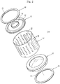
- FIG. 2 is an exploded perspective view of the rotary tub according to the present embodiment
- FIG. 3 is an assembled perspective view of the rotary tub according to the present embodiment.
- the rotary tub 30 includes a cylindrical body 31 having open front and rear parts, the through-holes 30a, and the lifters 30b, a front member 32 coupled to the open front part of the body 31 and having an opening 34 through which laundry is put into or removed from the body 31, and a rear member 33 coupled to the open rear part of the body 31 and the rotary shaft 51 to rotate the rotary tub 30.
- annular recess 35 which is formed approximately in the sectional shape of a '[' and is opened forward to receive the corresponding balancer 60.
- annular recess (not shown) which is open rearward to receive the corresponding balancer 60.
- the front member 32 and the rear member 33 are fitted in the front edge and the rear edge of the body 31 and fixed to the body 31 by screws or other suitable fixing members.
- the balancers 60 are mounted in the recesses 35 of the front and rear members 32 and 33.
- Each balancer 60 is constructed in the structure of an annular single race, in which a plurality of steel balls 61 are disposed and a viscous fluid is filled to control the moving speed of the balls 61.
- the balls 61 are movable in a circumferential direction such that, when a dynamic unbalance occurs at the rotary tub 30, the balls 61 move to a position symmetrical to the position where the dynamic unbalance occurs to reduce the vibration of the rotary tub 30.
- FIG. 4 is a control block diagram of the washing machine with the balancers according to the present embodiment.
- the washing machine includes a signal input unit 100, a vibration detection unit 110, a control unit 120, a drive unit 130, and a rotational frequency detection unit 140.
- the signal input unit 100 inputs operation information, such as a washing course (for example, a delicate washing course or a normal washing course), a washing temperature, spin-drying rpm, and additional rinsing, selected by a user, depending upon material to be laundered, to the control unit 120.
- operation information such as a washing course (for example, a delicate washing course or a normal washing course), a washing temperature, spin-drying rpm, and additional rinsing, selected by a user, depending upon material to be laundered, to the control unit 120.
- the vibration detection unit 110 detects vibration of the water tub 20 that is changed while the number of rotations of the motor 50 is maintained at a predetermined number of rotations (W-RPM: approximately 160 to 270 RPM) before excessive vibration is generated from the water tub 20 until the balls 61 reach the balancing position.
- the number of rotations at which the excessive vibration is generated (A-RPM) is approximately 270 RPM.
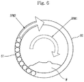
- the balancing position is the side opposite to concentrated laundry W causing the unbalance. Therefore, excessive vibration of the water tub 20 is prevented from being generated before the balls 61 reach the balancing position during a spin-drying operation of the washing machine with the balancers 60.
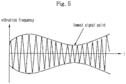
- a signal waveform of the vibration frequency as shown in FIG. 5 is detected by the vibration detection unit 110.
- the vibration frequency of FIG. 5 is a signal waveform generated due to a modulation phenomenon caused by the difference between the rotating speed (RPM1) of the rotary tub 30 and the rotating speed (RPM2) of the balls 61 as shown in FIG. 6 .
- the control unit 120 is a microcomputer to control the washing machine according to the operation information inputted from the signal input unit 100.
- the control unit 120 maintains the number of rotations of the motor 50 at the predetermined number of rotations (W-RPM) for a predetermined time (W-T1).
- W-RPM is the number of rotations at which the modulation phenomenon is easily observed while the vibration of the water tub does not exceed a predetermined value.
- W-T1 is the time calculated based on time taken until the number of rotations of the water tub reaches the number of excessive vibration rotations from the predetermined number of rotations.
- the number of rotations of the motor 50 is maintained at the predetermined time such that the motor 50 passes through the excessive vibration generating point of the water tub 20 during a spin-drying operation until the balls 61 reach the balancing position, and the control unit 120 reincreases the number of rotations of the motor 50 such the rotary tub 30 is rotated at high speed.
- the control unit 120 checks the vibration of the water tub 20 when reincreasing the number of rotations of the motor 50, and, when the vibration of the water tub 20 exceeds a predetermined vibration level (i.e., a reference vibration level considered as the excessive vibration of the water tub), brakes the motor 50 such that the RPM of the motor 50 is lowered to the predetermined number of rotations (W-RPM). Then the control unit 120 reincreases the RPM of the motor 50 to reliably reduce the excessive vibration of the water tub 20 during the spin-drying operation.
- a predetermined vibration level i.e., a reference vibration level considered as the excessive vibration of the water tub
- the control unit 120 sets a time (W-T2) necessary to brake the motor 50 such that the RPM of the motor 50 is lowered to the predetermined number of rotations (W-RPM) and reincreases the RPM of the motor 50 such that the excessive vibration passing point is located at half cycle. Therefore, the balls 61 are located at the balancing position after the brake of the motor 50.
- the time may be derived through experiments.
- the drive unit 130 drives the water supply valve 12, the drainage pump 16, and the motor 50 according to a drive control signal of the control unit 120.
- the rotational frequency detection unit 140 detects the number of rotations of the motor 50 to determine whether the RPM of the motor 50 is lowered by the brake of the motor 50 and inputs the detected number of rotations of the motor 50 to the control unit 120.
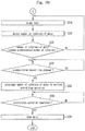
- FIGS. 7A and 7B are flow charts illustrating a process of reducing excessive vibration of the water tub in the washing machine with the balancers according to the present embodiment.
- the control unit 120 controls the drive unit 130 to drive the motor 50, and the spin-drying rotation of the rotary tub 30 is initiated by the motor 50 (S202).
- control unit 120 controls the motor 50 to be maintained at the predetermined number of rotations (W-RPM) before the motor 50 passes through the number of rotations (A-RPM) at the resonance point where the excessive vibration of the water tub 20 is generated, which is the excessive vibration generating point, until the balls 61 reach the balancing position during the spin-drying operation such that the motor 50 passes through the excessive vibration generating point of the water tub 20.
- the rotational frequency detection unit 140 detects the number of rotations of the motor 50, while the motor 50 performs the spin-drying rotation of the rotary tub 30, and inputs the detected number of rotations of the motor 50 to the control unit 120 (S204).
- the control unit 120 compares the number of rotations of the motor 50 detected by the rotational frequency detection unit 140 with the predetermined number of rotations (W-RPM) to determine whether the detected number of rotations of the motor 50 has reached the predetermined number of rotations (W-RPM) (S206).
- the number of rotations of the motor 50 is maintained as shown in FIGS. 8 and 9 (S208). If it is determined that the number of rotations of the motor 50 has not reached the predetermined number of rotations (W-RPM), the operation returns to S202.
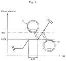
- FIG. 8 is a graph illustrating a ball behavior control process of reducing the excessive vibration of the water tub in the washing machine with the balancers according to the present embodiment
- FIG. 9 is a graph illustrating a rotational frequency control process of reducing the excessive vibration of the water tub in the washing machine with the balancers according to an embodiment not part of the present invention.
- the number of rotations of the motor 50 is maintained at the predetermined number of rotations (W-RPM) before the excessive vibration (Vmax) of the water tub 20 is generated until the balls 61 reach the balancing position.
- the signal waveform shown in FIG. 5 may be obtained by a device to detect the speed change or vibration of the water tub 20, for example, a vibration detection unit.
- the vibration frequency of FIG. 5 is a signal waveform generated due to a modulation phenomenon caused by the difference between the rotating speed (RPM1) of the rotary tub 30 and the rotating speed (RPM2) of the balls 61 as shown in FIG. 6 .
- the signal waveform is used to set the number of rotations of the motor 50 at which the modulation phenomenon caused by the difference between the rotating speed (RPM1) of the rotary tub 30 and the rotating speed (RPM2) of the balls is easily observed such that the spin-drying operation is performed while the vibration of the water tub 20 does not exceed the predetermined vibration level (Vmax), the reference vibration level considered as the excessive vibration of the water tub.
- control unit 120 counts the time taken to maintain the number of rotations of the motor 50 at the predetermined number of rotations (W-RPM) to determine whether a predetermined first time (W-T1) has elapsed (S210). When it is determined that the predetermined first time (W-T1) has elapsed, the control unit 120 performs the spin-drying operation while reincreasing the number of rotations of the motor 50 to a spin-drying RPM as shown in FIGS. 8 and 9 (S212). If it is determined that the predetermined first time (W-T1) has not elapsed, the operation returns to S208.
- W-RPM predetermined number of rotations
- the number of rotations of the motor 50 is reincreased after the number of rotations of the motor 50 is maintained at the predetermined number of rotations (W-RPM) for the predetermined first time (W-T1) or, not part of the invention, before the vibration frequency reaches the minimum level (i.e., the lowest signal point) while the control unit 120 continuously checks the signal waveform of the vibration frequency shown in FIG. 5 .
- the vibration detection unit 110 detects the vibration of the water tub 20 changed as the number of rotations of the motor 50 is reincreased and inputs the detected vibration to the control unit 120 (S214).
- the control unit 120 compares the vibration of the water tub 20 detected by the vibration detection unit 110 with the predetermined vibration level (Vmax) to determine whether the vibration of the water tub 20 exceeds the predetermined vibration level (Vmax) (S216).
- the control unit 120 brakes the motor 50 to lower the number of rotations of the motor 50 (S218). If it is determined that the vibration of the water tub 20 does not exceed the predetermined vibration level (Vmax), the operation returns to S212.
- the rotational frequency detection unit 140 detects the lowered number of rotations of the motor 50, and inputs the detected number of rotations of the motor 50 to the control unit 120 (S220).
- the control unit 120 determines whether the number of rotations of the motor 50 detected by the rotational frequency detection unit 140 has reached the predetermined number of rotations (W-RPM) (S222). When it is determined that the number of rotations of the motor 50 has not reached the predetermined number of rotations (W-RPM), the operation returns to S218 and the control unit 120 brakes the motor 50 to lower the RPM of the motor 50 until the number of rotations of the motor 50 reaches the predetermined number of rotations (W-RPM).
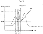
- the control unit 120 determines whether a predetermined second time (W-T2) has elapsed after the brake of the motor 50 (S224). When it is determined that the predetermined second time (W-T2) has elapsed, the control unit performs the spin-drying operation while reincreasing the number of rotations of the motor 50 to the spin-drying RPM as shown in FIG. 10 (S226). If it is determined that the predetermined second time (W-T2) has not elapsed, the operation returns to S224.
- W-T2 a predetermined second time
- the number of rotations of the motor 50 may be reincreased after the number of rotations of the motor 50 is maintained at the predetermined number of rotations (W-RPM) for the predetermined second time (W-T2), or the time point where the number of rotations of the motor 50 is reincreased may be derived through experiments such that the excessive vibration (Vmax) passing point is located at half cycle.
- FIG. 10 is a graph illustrating a brake control process of reducing the excessive vibration of the water tub in the washing machine with the balancers according to the present embodiment.
- the control unit brakes the motor 50 such that the RPM of the motor is rapidly lowered to the predetermined number of rotations (W-RPM) to reliably reduce the vibrations of the water tub 20, and reincreases the number of rotations of the motor 50, after the predetermined second time (W-T2) has elapsed, to reduce the magnitude and deviation of the excessive vibration of the water tub 20.
- W-RPM predetermined number of rotations
- W-T2 predetermined second time
- the control unit 120 stops the operation of the motor 50 (S230). If it is not determined that the spin-drying operation has not been completed, the operation returns to S228.
- the process of reducing the excessive vibration of the water tub 20 generated during the spin-drying operation was described.
- the present embodiment is not limited to the spin-drying operation.
- the present embodiment may be applied to any operation in which the vibration of the water tub 20 may be generated before the balls reach a balancing position in the washing machine with the balancers 60.
- the present embodiment provides a washing machine and a control method thereof that is capable of reincreasing the number of rotations of a motor after maintaining the number of rotations of the motor at a predetermined number of rotations before excessive vibration of a water tub is generated for a predetermined time such that the motor passes through an excessive vibration generating point of the water tub. Consequently, the present embodiment has the effect of reducing the excessive vibration of the water tub generated before balls reach the balancing position.
- the present embodiment provides a washing machine and a control method thereof that is capable of braking the motor, when the water tub is vibrated at more than a predetermined vibration level after reincreasing the RPM of the motor, to lower the RPM of the motor to a predetermined number of rotations, and reincreasing the RPM of the motor, whereby the excessive vibration of the water tub is prevented based on not the probability but the control. Consequently, the present embodiment has the effect of reliably reducing the excessive vibration of the water tub.
Landscapes
- Engineering & Computer Science (AREA)
- Textile Engineering (AREA)
- Control Of Washing Machine And Dryer (AREA)
- Main Body Construction Of Washing Machines And Laundry Dryers (AREA)
Claims (4)
- Steuerverfahren zur Steuerung einer Waschmaschine mit einem Motor (50), einem Wasserbehälter (20) und einem Drehbehälter (30) mit Ausgleichseinheiten (60), wobei das Steuerverfahren umfasst:i) In-Drehung-Versetzen (S202) des Drehbehälters (30);ii) Beibehalten (S208) einer Drehgeschwindigkeit des Drehbehälters (30) auf einer vorbestimmten Drehgeschwindigkeit (W-RPM) während einer ersten vorbestimmten Zeitdauer (W-T1); undiii) Erhöhen (S212) der Drehgeschwindigkeit des Drehbehälters (30) nach dem Verstreichen der ersten vorbestimmten Zeitdauer (W-T1) zur Ausführung eines Rotationstrocknungsvorgangs der Waschmaschine,gekennzeichnet durch die Schritte:iv) Erfassen (S214) einer Schwingung des Wasserbehälters (20) während der Erhöhung (S212) der Drehgeschwindigkeit des Drehbehälters (30);v) Abbremsen (S218) des Motors (50) derart, dass die Drehgeschwindigkeit des Drehbehälters (30) abgesenkt wird, beruhend darauf, dass ermittelt wird, dass die erfasste Schwingung des Wasserbehälters (20) einen vorbestimmten Schwingungspegel übersteigt (S216);vi) Beibehalten (S222, S224) der Drehgeschwindigkeit des Drehbehälters (30) bei der vorbestimmten Drehgeschwindigkeit (W-RPM); undvii) Erhöhen (S226) der Drehgeschwindigkeit der Drehbehälters (30) beruhend darauf, dass ermittelt wird, dass eine zweite vorbestimmte Zeitdauer (W-T2) nach dem Abbremsen (S218) des Motors verstrichen ist, während die Drehgeschwindigkeit des Drehbehälters (30) auf der vorbestimmten Drehgeschwindigkeit (W-RPM) gehalten wird.
- Steuerverfahren nach Anspruch 1, wobei die vorbestimmte Drehgeschwindigkeit (W-RPM) niedriger als 270 UpM ist.
- Steuerverfahren nach Anspruch 2, wobei die vorbestimmte Drehgeschwindigkeit (W-RPM) höher als 160 UpM ist.
- Waschmaschine mit einer Steuereinheit (120), die ausgebildet ist, die Waschmaschine mittels des Steuerverfahrens nach einem der vorhergehenden Ansprüche zu steuern.
Applications Claiming Priority (1)
| Application Number | Priority Date | Filing Date | Title |
|---|---|---|---|
| KR1020070007606A KR101428477B1 (ko) | 2007-01-24 | 2007-01-24 | 세탁기 및 그 제어방법 |
Publications (2)
| Publication Number | Publication Date |
|---|---|
| EP1950336A1 EP1950336A1 (de) | 2008-07-30 |
| EP1950336B1 true EP1950336B1 (de) | 2019-01-02 |
Family
ID=39410355
Family Applications (1)
| Application Number | Title | Priority Date | Filing Date |
|---|---|---|---|
| EP07120221.2A Active EP1950336B1 (de) | 2007-01-24 | 2007-11-08 | Waschmaschine mit Ausgleichsreglern und Steuerverfahren dafür |
Country Status (4)
| Country | Link |
|---|---|
| US (1) | US20080172805A1 (de) |
| EP (1) | EP1950336B1 (de) |
| KR (1) | KR101428477B1 (de) |
| CN (1) | CN101230532B (de) |
Families Citing this family (27)
| Publication number | Priority date | Publication date | Assignee | Title |
|---|---|---|---|---|
| KR101407959B1 (ko) | 2008-01-22 | 2014-06-20 | 삼성전자주식회사 | 볼 밸런서를 구비한 드럼 세탁기 및 그 제어방법 |
| US9416478B2 (en) | 2009-03-31 | 2016-08-16 | Lg Electronics Inc. | Washing machine and washing method |
| KR101526976B1 (ko) * | 2008-08-06 | 2015-06-11 | 엘지전자 주식회사 | 세탁장치의 제어방법 |
| BRPI1007520B1 (pt) | 2009-02-11 | 2020-11-03 | Lg Electronics Inc. | método de lavagem para uma máquina de lavar |
| US10533275B2 (en) | 2009-07-27 | 2020-01-14 | Lg Electronics Inc. | Control method of a laundry machine |
| US9822473B2 (en) | 2009-07-27 | 2017-11-21 | Lg Electronics Inc. | Control method of a laundry machine |
| US9234307B2 (en) | 2009-07-27 | 2016-01-12 | Lg Electronics Inc. | Control method of a laundry machine |
| WO2011025320A2 (en) * | 2009-08-27 | 2011-03-03 | Lg Electronics Inc. | Control method of laundry machine |
| EP2470711B1 (de) * | 2009-08-27 | 2017-05-24 | LG Electronics Inc. | Steuerverfahren für eine waschmaschine |
| EP2470708B1 (de) * | 2009-08-27 | 2017-08-09 | LG Electronics Inc. | Steuerverfahren für eine waschmaschine |
| WO2011025319A1 (en) * | 2009-08-27 | 2011-03-03 | Lg Electronics Inc. | Control method of laundry machine |
| KR101710388B1 (ko) * | 2009-08-27 | 2017-02-27 | 엘지전자 주식회사 | 세탁장치의 탈수행정 제어방법 |
| EP2470710B1 (de) * | 2009-08-27 | 2017-10-04 | LG Electronics Inc. | Steuerverfahren für eine waschmaschine |
| CN102549208B (zh) * | 2009-08-27 | 2015-07-08 | Lg电子株式会社 | 洗衣机的控制方法 |
| RU2506360C2 (ru) | 2009-08-27 | 2014-02-10 | Эл Джи Электроникс Инк. | Способ управления машиной для обработки белья |
| KR101940529B1 (ko) * | 2009-08-27 | 2019-01-21 | 엘지전자 주식회사 | 세탁장치의 탈수행정 제어방법 |
| KR101667576B1 (ko) * | 2009-08-27 | 2016-10-19 | 엘지전자 주식회사 | 세탁장치의 탈수행정 제어방법 |
| US8776297B2 (en) | 2009-10-13 | 2014-07-15 | Lg Electronics Inc. | Laundry treating apparatus and method |
| JP5861116B2 (ja) * | 2011-04-21 | 2016-02-16 | パナソニックIpマネジメント株式会社 | 乾燥装置 |
| CN104246050B (zh) * | 2012-04-23 | 2016-09-21 | 松下知识产权经营株式会社 | 滚筒式洗衣机 |
| US9493897B2 (en) * | 2013-06-25 | 2016-11-15 | Whirlpool Corporation | Method of operation for a laundry treating appliance having a ball balance ring |
| KR102089969B1 (ko) | 2013-07-12 | 2020-03-17 | 삼성전자주식회사 | 밸런서를 구비한 세탁기 및 그 제어방법 |
| KR20150075626A (ko) * | 2013-12-26 | 2015-07-06 | 동부대우전자 주식회사 | 세탁기의 진동 저감 장치 및 방법 |
| US9809916B2 (en) * | 2014-02-19 | 2017-11-07 | Samsung Electronics Co., Ltd. | Washing machine with balancer and control method thereof |
| US10066333B2 (en) * | 2014-02-21 | 2018-09-04 | Samsung Electronics Co., Ltd. | Washing machine with ball balancer and method of controlling vibration reduction thereof |
| JP6550329B2 (ja) * | 2014-12-26 | 2019-07-24 | 三星電子株式会社Samsung Electronics Co.,Ltd. | 洗濯機の脱水時における振動低減方法 |
| KR102608614B1 (ko) | 2018-09-21 | 2023-12-04 | 삼성전자주식회사 | 전자 장치 및 이의 제어 방법 |
Citations (4)
| Publication number | Priority date | Publication date | Assignee | Title |
|---|---|---|---|---|
| EP0704567A1 (de) * | 1994-09-28 | 1996-04-03 | ELECTROLUX ZANUSSI ELETTRODOMESTICI S.p.A. | Vorrichtung zum Vermeiden der Unwucht in Wäschewaschmaschinen |
| US20050016227A1 (en) * | 2003-07-25 | 2005-01-27 | Lee Phal Jin | Washington machine and method of performing spinning operation |
| EP1533411A2 (de) * | 2003-11-18 | 2005-05-25 | Samsung Electronics Co., Ltd. | Waschmaschine und Verfahren zur Steuerung dieser Waschmaschine |
| US20050283919A1 (en) * | 2004-06-25 | 2005-12-29 | Lg Electronics Inc. | Method for controlling spinning in drum-type washing machine |
Family Cites Families (16)
| Publication number | Priority date | Publication date | Assignee | Title |
|---|---|---|---|---|
| NZ207319A (en) * | 1984-02-29 | 1988-02-12 | Fisher & Paykel | Clothes washing machine, control of spin cycle and of washing during water entry |
| US4782544A (en) * | 1987-04-16 | 1988-11-08 | Whirlpool Corporation | Water extraction method and control for automatic washer |
| SE461279B (sv) * | 1988-05-30 | 1990-01-29 | Electrolux Ab | Metod foer balansering av en kring en vaesentligen horisontell axel roterande behaallare |
| JPH09313766A (ja) * | 1996-01-31 | 1997-12-09 | Sharp Corp | ドラム式乾燥洗濯機、ドラム式乾燥機およびドラム式乾燥洗濯機の動作方法 |
| JP3536566B2 (ja) * | 1997-01-24 | 2004-06-14 | 松下電器産業株式会社 | 洗濯機 |
| KR100207025B1 (ko) * | 1997-04-18 | 1999-08-02 | 윤종용 | 세탁기의 제어방법 |
| DE19718321C1 (de) * | 1997-04-30 | 1998-10-29 | Miele & Cie | Verfahren zum Auswuchten von rotierenden Körpern |
| EP0924330B1 (de) | 1997-12-20 | 2002-11-06 | Miele & Cie. GmbH & Co. | Trommelwaschmaschine oder Waschtrockner bzw. Verfahren zum Waschen und Schleudern von Waschgut in einer Waschmaschine oder einem Waschtrockner |
| DE19952464C2 (de) | 1999-10-29 | 2002-05-08 | Miele & Cie | Verfahren zum Auswuchten eines rotierenden Körpers, der durch einen geregelten Antrieb in Rotation versetzt wird, und Verwendung des Verfahrens |
| US6578225B2 (en) * | 2000-05-25 | 2003-06-17 | Skf Autobalance Systems Ab | Low-speed prebalancing for washing machines |
| US6647575B2 (en) * | 2000-06-23 | 2003-11-18 | Whirlpool Corporation | Method and apparatus for reducing wash tub displacement during spin cycle ramp-up |
| CN100378368C (zh) * | 2002-05-22 | 2008-04-02 | 戴森技术有限公司 | 自动平衡装置 |
| KR100493300B1 (ko) * | 2002-11-25 | 2005-06-07 | 엘지전자 주식회사 | 세탁기의 탈수 제어장치 및 그 방법 |
| US7530133B2 (en) * | 2005-02-18 | 2009-05-12 | Whirlpool Corporation | Method for controlling a spin cycle in a washing machine |
| KR101085495B1 (ko) | 2006-11-06 | 2011-11-23 | 삼성전자주식회사 | 드럼 세탁기의 터브 진동제어방법 |
| KR101156713B1 (ko) | 2006-11-06 | 2012-06-15 | 삼성전자주식회사 | 드럼 세탁기 및 그 제어방법 |
-
2007
- 2007-01-24 KR KR1020070007606A patent/KR101428477B1/ko active Active
- 2007-10-19 US US11/976,069 patent/US20080172805A1/en not_active Abandoned
- 2007-11-08 EP EP07120221.2A patent/EP1950336B1/de active Active
- 2007-11-09 CN CN2007101860293A patent/CN101230532B/zh not_active Expired - Fee Related
Patent Citations (4)
| Publication number | Priority date | Publication date | Assignee | Title |
|---|---|---|---|---|
| EP0704567A1 (de) * | 1994-09-28 | 1996-04-03 | ELECTROLUX ZANUSSI ELETTRODOMESTICI S.p.A. | Vorrichtung zum Vermeiden der Unwucht in Wäschewaschmaschinen |
| US20050016227A1 (en) * | 2003-07-25 | 2005-01-27 | Lee Phal Jin | Washington machine and method of performing spinning operation |
| EP1533411A2 (de) * | 2003-11-18 | 2005-05-25 | Samsung Electronics Co., Ltd. | Waschmaschine und Verfahren zur Steuerung dieser Waschmaschine |
| US20050283919A1 (en) * | 2004-06-25 | 2005-12-29 | Lg Electronics Inc. | Method for controlling spinning in drum-type washing machine |
Also Published As
| Publication number | Publication date |
|---|---|
| CN101230532A (zh) | 2008-07-30 |
| EP1950336A1 (de) | 2008-07-30 |
| KR20080069857A (ko) | 2008-07-29 |
| KR101428477B1 (ko) | 2014-08-12 |
| US20080172805A1 (en) | 2008-07-24 |
| CN101230532B (zh) | 2011-10-12 |
Similar Documents
| Publication | Publication Date | Title |
|---|---|---|
| EP1950336B1 (de) | Waschmaschine mit Ausgleichsreglern und Steuerverfahren dafür | |
| US8156592B2 (en) | Washing machine and method of controlling the same | |
| CN101177872B (zh) | 洗衣机和控制所述洗衣机的方法 | |
| CN101492874B (zh) | 具有球平衡物的滚筒型洗衣机及其控制方法 | |
| CN103031697B (zh) | 具有球平衡器的洗衣机 | |
| EP2826906B1 (de) | Waschmaschine und steuerungsverfahren dafür | |
| JP3762611B2 (ja) | ドラム式洗濯機 | |
| CN104846581B (zh) | 具有平衡器的洗衣机及其控制方法 | |
| EP3617372B1 (de) | Verfahren zum steuern des schleudergangs eines wäschepflegegeräts | |
| JP5176662B2 (ja) | ドラム式洗濯機 | |
| JP4307335B2 (ja) | ドラム式洗濯機 | |
| JP3754377B2 (ja) | ドラム式洗濯機およびドラム式洗濯機における脱水時の振動低減方法 | |
| KR101386506B1 (ko) | 세탁기 및 그 제어방법 | |
| KR101138882B1 (ko) | 세탁기 및 그 탈수제어방법 | |
| KR100347941B1 (ko) | 세탁기의 언밸런스 제어 방법 | |
| JP2025165721A (ja) | ドラム式洗濯機 | |
| JP2025126941A (ja) | ドラム式洗濯機 |
Legal Events
| Date | Code | Title | Description |
|---|---|---|---|
| PUAI | Public reference made under article 153(3) epc to a published international application that has entered the european phase |
Free format text: ORIGINAL CODE: 0009012 |
|
| AK | Designated contracting states |
Kind code of ref document: A1 Designated state(s): AT BE BG CH CY CZ DE DK EE ES FI FR GB GR HU IE IS IT LI LT LU LV MC MT NL PL PT RO SE SI SK TR |
|
| AX | Request for extension of the european patent |
Extension state: AL BA HR MK RS |
|
| 17P | Request for examination filed |
Effective date: 20080930 |
|
| 17Q | First examination report despatched |
Effective date: 20081030 |
|
| AKX | Designation fees paid |
Designated state(s): DE FR GB |
|
| RAP1 | Party data changed (applicant data changed or rights of an application transferred) |
Owner name: SAMSUNG ELECTRONICS CO., LTD. |
|
| GRAP | Despatch of communication of intention to grant a patent |
Free format text: ORIGINAL CODE: EPIDOSNIGR1 |
|
| INTG | Intention to grant announced |
Effective date: 20180621 |
|
| GRAS | Grant fee paid |
Free format text: ORIGINAL CODE: EPIDOSNIGR3 |
|
| GRAA | (expected) grant |
Free format text: ORIGINAL CODE: 0009210 |
|
| AK | Designated contracting states |
Kind code of ref document: B1 Designated state(s): DE FR GB |
|
| REG | Reference to a national code |
Ref country code: GB Ref legal event code: FG4D |
|
| REG | Reference to a national code |
Ref country code: DE Ref legal event code: R096 Ref document number: 602007057302 Country of ref document: DE |
|
| REG | Reference to a national code |
Ref country code: DE Ref legal event code: R097 Ref document number: 602007057302 Country of ref document: DE |
|
| PLBE | No opposition filed within time limit |
Free format text: ORIGINAL CODE: 0009261 |
|
| STAA | Information on the status of an ep patent application or granted ep patent |
Free format text: STATUS: NO OPPOSITION FILED WITHIN TIME LIMIT |
|
| 26N | No opposition filed |
Effective date: 20191003 |
|
| PGFP | Annual fee paid to national office [announced via postgrant information from national office to epo] |
Ref country code: FR Payment date: 20211022 Year of fee payment: 15 |
|
| PG25 | Lapsed in a contracting state [announced via postgrant information from national office to epo] |
Ref country code: FR Free format text: LAPSE BECAUSE OF NON-PAYMENT OF DUE FEES Effective date: 20221130 |
|
| PGFP | Annual fee paid to national office [announced via postgrant information from national office to epo] |
Ref country code: DE Payment date: 20251002 Year of fee payment: 19 |
|
| PGFP | Annual fee paid to national office [announced via postgrant information from national office to epo] |
Ref country code: GB Payment date: 20251001 Year of fee payment: 19 |