EP1943437B2 - Kombination aus einem torsionsschwingungsdämpfer mit einer kurbelwelle - Google Patents
Kombination aus einem torsionsschwingungsdämpfer mit einer kurbelwelle Download PDFInfo
- Publication number
- EP1943437B2 EP1943437B2 EP06828913.1A EP06828913A EP1943437B2 EP 1943437 B2 EP1943437 B2 EP 1943437B2 EP 06828913 A EP06828913 A EP 06828913A EP 1943437 B2 EP1943437 B2 EP 1943437B2
- Authority
- EP
- European Patent Office
- Prior art keywords
- primary
- clutch
- radially
- crankshaft
- vibration damper
- Prior art date
- Legal status (The legal status is an assumption and is not a legal conclusion. Google has not performed a legal analysis and makes no representation as to the accuracy of the status listed.)
- Active
Links
- 230000005540 biological transmission Effects 0.000 claims description 23
- 230000008878 coupling Effects 0.000 claims description 16
- 238000010168 coupling process Methods 0.000 claims description 16
- 238000005859 coupling reaction Methods 0.000 claims description 16
- 238000003860 storage Methods 0.000 description 22
- 239000000969 carrier Substances 0.000 description 18
- 238000002485 combustion reaction Methods 0.000 description 8
- 238000010276 construction Methods 0.000 description 6
- 229910000831 Steel Inorganic materials 0.000 description 4
- 238000011161 development Methods 0.000 description 4
- 230000018109 developmental process Effects 0.000 description 4
- 230000002028 premature Effects 0.000 description 4
- 239000007787 solid Substances 0.000 description 4
- 239000010959 steel Substances 0.000 description 4
- 238000004519 manufacturing process Methods 0.000 description 3
- 239000002184 metal Substances 0.000 description 3
- 230000007935 neutral effect Effects 0.000 description 3
- 238000010521 absorption reaction Methods 0.000 description 2
- 238000000151 deposition Methods 0.000 description 2
- 230000000694 effects Effects 0.000 description 2
- 238000009434 installation Methods 0.000 description 2
- 230000001788 irregular Effects 0.000 description 2
- 238000005304 joining Methods 0.000 description 2
- 241000446313 Lamella Species 0.000 description 1
- 238000013016 damping Methods 0.000 description 1
- 230000008021 deposition Effects 0.000 description 1
- 230000009977 dual effect Effects 0.000 description 1
- 239000000446 fuel Substances 0.000 description 1
- 238000012986 modification Methods 0.000 description 1
- 230000004048 modification Effects 0.000 description 1
- 230000003071 parasitic effect Effects 0.000 description 1
- 238000005096 rolling process Methods 0.000 description 1
- 238000003466 welding Methods 0.000 description 1
Images

Classifications
-
- F—MECHANICAL ENGINEERING; LIGHTING; HEATING; WEAPONS; BLASTING
- F16—ENGINEERING ELEMENTS AND UNITS; GENERAL MEASURES FOR PRODUCING AND MAINTAINING EFFECTIVE FUNCTIONING OF MACHINES OR INSTALLATIONS; THERMAL INSULATION IN GENERAL
- F16F—SPRINGS; SHOCK-ABSORBERS; MEANS FOR DAMPING VIBRATION
- F16F15/00—Suppression of vibrations in systems; Means or arrangements for avoiding or reducing out-of-balance forces, e.g. due to motion
- F16F15/10—Suppression of vibrations in rotating systems by making use of members moving with the system
- F16F15/12—Suppression of vibrations in rotating systems by making use of members moving with the system using elastic members or friction-damping members, e.g. between a rotating shaft and a gyratory mass mounted thereon
- F16F15/131—Suppression of vibrations in rotating systems by making use of members moving with the system using elastic members or friction-damping members, e.g. between a rotating shaft and a gyratory mass mounted thereon the rotating system comprising two or more gyratory masses
- F16F15/13164—Suppression of vibrations in rotating systems by making use of members moving with the system using elastic members or friction-damping members, e.g. between a rotating shaft and a gyratory mass mounted thereon the rotating system comprising two or more gyratory masses characterised by the supporting arrangement of the damper unit
-
- F—MECHANICAL ENGINEERING; LIGHTING; HEATING; WEAPONS; BLASTING
- F16—ENGINEERING ELEMENTS AND UNITS; GENERAL MEASURES FOR PRODUCING AND MAINTAINING EFFECTIVE FUNCTIONING OF MACHINES OR INSTALLATIONS; THERMAL INSULATION IN GENERAL
- F16D—COUPLINGS FOR TRANSMITTING ROTATION; CLUTCHES; BRAKES
- F16D21/00—Systems comprising a plurality of actuated clutches
- F16D21/02—Systems comprising a plurality of actuated clutches for interconnecting three or more shafts or other transmission members in different ways
- F16D21/06—Systems comprising a plurality of actuated clutches for interconnecting three or more shafts or other transmission members in different ways at least two driving shafts or two driven shafts being concentric
-
- F—MECHANICAL ENGINEERING; LIGHTING; HEATING; WEAPONS; BLASTING
- F16—ENGINEERING ELEMENTS AND UNITS; GENERAL MEASURES FOR PRODUCING AND MAINTAINING EFFECTIVE FUNCTIONING OF MACHINES OR INSTALLATIONS; THERMAL INSULATION IN GENERAL
- F16D—COUPLINGS FOR TRANSMITTING ROTATION; CLUTCHES; BRAKES
- F16D25/00—Fluid-actuated clutches
- F16D25/06—Fluid-actuated clutches in which the fluid actuates a piston incorporated in, i.e. rotating with the clutch
- F16D25/062—Fluid-actuated clutches in which the fluid actuates a piston incorporated in, i.e. rotating with the clutch the clutch having friction surfaces
- F16D25/063—Fluid-actuated clutches in which the fluid actuates a piston incorporated in, i.e. rotating with the clutch the clutch having friction surfaces with clutch members exclusively moving axially
- F16D25/0635—Fluid-actuated clutches in which the fluid actuates a piston incorporated in, i.e. rotating with the clutch the clutch having friction surfaces with clutch members exclusively moving axially with flat friction surfaces, e.g. discs
- F16D25/0638—Fluid-actuated clutches in which the fluid actuates a piston incorporated in, i.e. rotating with the clutch the clutch having friction surfaces with clutch members exclusively moving axially with flat friction surfaces, e.g. discs with more than two discs, e.g. multiple lamellae
-
- F—MECHANICAL ENGINEERING; LIGHTING; HEATING; WEAPONS; BLASTING
- F16—ENGINEERING ELEMENTS AND UNITS; GENERAL MEASURES FOR PRODUCING AND MAINTAINING EFFECTIVE FUNCTIONING OF MACHINES OR INSTALLATIONS; THERMAL INSULATION IN GENERAL
- F16D—COUPLINGS FOR TRANSMITTING ROTATION; CLUTCHES; BRAKES
- F16D25/00—Fluid-actuated clutches
- F16D25/10—Clutch systems with a plurality of fluid-actuated clutches
-
- F—MECHANICAL ENGINEERING; LIGHTING; HEATING; WEAPONS; BLASTING
- F16—ENGINEERING ELEMENTS AND UNITS; GENERAL MEASURES FOR PRODUCING AND MAINTAINING EFFECTIVE FUNCTIONING OF MACHINES OR INSTALLATIONS; THERMAL INSULATION IN GENERAL
- F16D—COUPLINGS FOR TRANSMITTING ROTATION; CLUTCHES; BRAKES
- F16D21/00—Systems comprising a plurality of actuated clutches
- F16D21/02—Systems comprising a plurality of actuated clutches for interconnecting three or more shafts or other transmission members in different ways
- F16D21/06—Systems comprising a plurality of actuated clutches for interconnecting three or more shafts or other transmission members in different ways at least two driving shafts or two driven shafts being concentric
- F16D2021/0661—Hydraulically actuated multiple lamellae clutches
Definitions
- the invention relates to a combination of a crankshaft and a torsional vibration damper and such a combination in conjunction with a clutch.
- Torsional or torsional vibration dampers are known from the prior art in a variety of modifications and from various areas of application.
- they are used in motor vehicle construction for the elastic coupling of the internal combustion engine and the drive train. This is intended to prevent vibrations from being transmitted from the side of the internal combustion engine to the drive train or the transmission.
- Such a transmission of vibrations occurs in motor vehicle drives, especially in internal combustion engines with comparatively few cylinders and at low speeds. If such vibrations are effectively damped, the internal combustion engine can be operated at lower speeds, which generally results in reduced fuel consumption and is therefore both economically and ecologically advantageous.
- Torsional vibration dampers are known with a drive-side primary element and an output-side secondary element, the primary and secondary elements being coupled to one another in the circumferential direction via a spring device and being rotatable relative to one another about a neutral position.
- the primary and secondary elements each include at least one driver, which are referred to below as primary drivers and secondary drivers, respectively.
- a torque applied to the primary element on the drive side is first transmitted to the spring device by means of the primary driver and from there to the secondary driver of the secondary element.
- the spring device mentioned consists, for example, of one or more spring elements arranged one behind the other in the circumferential direction of the annular part of the torsional vibration damper, which are preferably designed as coil springs or coil spring sets. Sliding shoes are arranged between the spring elements and connect the successive spring elements with one another. End shoes are arranged on both ends of the spring devices, which support the spring device against the respective drivers. Instead of sliding shoes, so-called divider plates can also be provided in order to separate the individual spring elements from one another. Different design variants are, for example, in the European patent application with the application number 04 008 489.9 described.
- the DE 34 27 163 A1 describes the connection of a crankshaft to the primary mass of a torsional vibration damper by means of a flywheel, the primary mass being movable in the axial direction relative to the flywheel.
- the DE 199 57 978 A1 describes a combination of a torsional vibration damper and a crankshaft in which the primary mass is connected to the crankshaft without play.
- the primary mass and secondary mass of the damper are arranged in such a way that they can be moved relative to one another in the axial direction. Similar combinations are also from the DE 195 22 718 A1 , the FR 2 858 674 and the DE 34 11 090 A1 known, in which the primary sides of the damper are also connected to the crankshaft without play.
- the invention is now based on the object of designing and developing a combination of crankshaft and torsional vibration damper of the generic type in such a way that components connected on the output side and the torsional vibration damper itself are less prone to premature wear than systems or torsional vibration dampers according to the prior art and that noise development in the operation is reduced.
- the invention is based, among other things, on the knowledge that when operating a clutch damper module, movement irregularities and noises occur, among other things, because the damper primary mass, that is, the drive-side part of the torsional damper, is not connected to the engine mass without play.
- the invention provides that the primary element is indirectly connected to the crankshaft in the axial direction without play or is directly connected.
- the backlash-free coupling in the axial direction initially prevents the development of noise and the relative movement between the crankshaft, possibly a flywheel, a flex plate and the primary element of the torsional vibration damper, depending on which of the parts mentioned are provided in the drive chain.
- the invention accepts that these are absorbed in the area of the torsional vibration damper.
- the play-free connections can be designed as fixed or advantageously detachable joining connections.
- the corresponding movements can be absorbed particularly easily in that the primary element can be displaced in the axial direction relative to the secondary element.
- the primary element or the secondary element is connected to a hollow ring in which spring elements for coupling the primary element to the secondary element are guided
- the ring has at least one opening for engagement of the each has a different one of the elements.
- the invention also provides that the primary element is mounted directly or indirectly in the axial direction on a rotatable part connected to the secondary element and that the play of the rotatable part in the axial direction is greater than the axial play of the crankshaft and the primary element.
- This rotatable part can, for example, be part of a clutch connected to the secondary part on the output side. This effectively limits the axial play in the drive train between the engine, the crankshaft and the torsional vibration damper. By mounting the individual parts in the axial direction against each other, rattling noises are reduced and wear caused by axial impact is prevented.
- the invention further advantageously provides that the primary element is connected to a flywheel that is connected to the crankshaft without axial play.
- the flywheel supports the desired effect by damping irregular movements, especially in the circumferential direction, but also in the axial direction simply through its mass.
- flex plates are common in themselves and represent a wobble-soft disk that is arranged in the drive train and which can also dampen vibrations and compensate for radial or axial offsets as well as tilting of rotation axes.
- the primary part can be mounted indirectly or directly radially.
- the radial mounting of the primary part can be achieved, for example, by a bearing in the area of the primary part that acts as a floating bearing in the axial direction and can be designed as a rolling or plain bearing.
- the radial bearing can take place, for example, on a transmission shaft or on a transmission housing/clutch housing.
- the joining connection between the primary element and the flywheel has means for compensating for the tolerances during assembly.
- the means of compensating the tolerances can For example, be formed by screw connections in the radial or axial direction with correspondingly provided elongated holes.
- the drive train can first be assembled with imbalances that are as minimized as possible, which, in addition to the measures already mentioned, leads to an increase in synchronism in both the axial and circumferential directions.
- Corresponding means for tolerance compensation can also be provided between the primary element and the flex plate or between the flex plate and the flywheel.
- the invention also advantageously provides a device for absorbing or compensating for the radial forces, which is part of the secondary element of the torsional vibration damper.
- a compensation device or force absorption device prevents the parasitic radial forces from being passed on to downstream components, in particular, for example, to a downstream clutch.
- a compensation device or force absorption device of the type according to the invention can be realized, for example, in that the secondary element itself is rotatably mounted. This means that the storage is not carried out using components of downstream components, in particular components driven by the torsional vibration damper. If one assumes, for example, a combination of a torsional vibration damper and a clutch, e.g. a double clutch, the invention provides that not (only) the clutch or parts of the clutch are mounted accordingly, but that the secondary side of the torsional vibration damper is preferably in the torque transfer area between the torsional vibration damper and coupling is supported by bearings. In technical language, this bearing can also be referred to as the deposit of the secondary side of the torsional vibration damper. The forces occurring in the secondary side of the damper due to imbalances or the like are absorbed in this way within the torsional vibration damper. The additional bearing is virtually integrated into the design of the damper and clutch.
- Another advantage of depositing the secondary side of the damper at or in front of the torque transfer point to the downstream clutch is that the total clutch play can be adjusted independently of the play setting on the torsional vibration damper.
- damper constructions can be used which completely dispense with a play adjustment or whose primary side, as a flex element, makes the clutch damper unit independent of axial movements of the drive shaft, in particular, for example, a crankshaft.
- the secondary element comprises a secondary part element facing the output side and that the secondary part element facing the output side is rotatably, in particular radially, mounted.
- a coupling between the secondary part element facing the output side and the downstream component, e.g. the downstream clutch, enables radial forces coming from the torsional vibration damper to be cushioned/compensated directly at the torque transfer point. Damage to the downstream components, especially the clutch, is efficiently prevented in this way.
- the invention provides that the secondary element comprises a secondary part element facing the drive side and that the secondary part element facing the drive side is rotatably, in particular radially, mounted.
- the alternative variant can be advantageous for reasons of space, the additional variant guarantees even more effective shielding of radial forces on downstream components, in particular a downstream (double) clutch.
- the secondary element in particular the secondary part element facing the output side and/or the secondary part element facing the drive side, is mounted directly or indirectly rotatable, in particular radially, on a shaft.
- This type of storage is characterized by the fact that very small imbalances can be achieved through the coaxial positioning.
- the assembly of the clutch module can be made easier with indirect storage via the hub of the inner disk carrier of the radially outer clutch.
- the secondary element in particular the secondary part element facing the output side and/or the secondary part element facing the drive side, is rotatably mounted, in particular radially, directly or indirectly on a, preferably non-rotating, carrier carrying the torsional vibration damper.
- This type of storage is characterized by the fact that the radial forces can be absorbed directly or indirectly by the carrier.
- the invention provides, for example, that the secondary element, in particular the secondary part element facing the output side and/or the secondary part element facing the drive side, is rotatably mounted, in particular radially, directly or indirectly on a primary hub of the primary element.
- This variant is characterized by the fact that by aligning the secondary-side parts with the primary-side parts, the secondary-side and primary-side rotation axes are identical and thus damage to the damper components due to wear is most efficiently prevented.
- the invention provides for the secondary element, in particular the secondary part element facing the output side and/or the secondary part element facing the drive side, to be rotatable, in particular radially, directly or indirectly on a clutch hub of a clutch which can be driven indirectly or directly via the torsional vibration damper, in particular a double clutch. to store.
- the advantage of this type of storage is that an axially short design can be achieved.
- An alternative storage consists in connecting the secondary element, in particular the secondary part element facing the output side and/or the secondary part element facing the drive side, directly or indirectly on a disk carrier hub of a disk carrier to a clutch, in particular a double clutch, which can be driven indirectly or directly via the torsional vibration damper, preferably radially to store.
- a clutch in particular a double clutch, which can be driven indirectly or directly via the torsional vibration damper, preferably radially to store.
- the invention also provides, as an alternative or in addition, for the secondary element, in particular the secondary part element facing the output side and/or the secondary part element facing the drive side, to be axially supported.
- the secondary element in particular the secondary part element facing the output side and/or the secondary part element facing the drive side, to be axially supported.
- axial forces can be absorbed that are caused by radial offsets or imbalances.
- storage can mitigate premature signs of wear on the damper and downstream components.
- such a storage enables axial positioning of the components driven by the damper, for example a clutch, with respect to the damper.
- Axial storage can be achieved very easily, at least on one side, in that the secondary element, in particular the secondary part element facing the output side and/or the secondary part element facing the drive side, is axially mounted on the primary element.
- the secondary element in particular the secondary part element facing the output side and/or the secondary part element facing the drive side, is axially mounted at least on one side on a disk carrier of the clutch.
- This variant is characterized by the fact that a particularly compact design is possible.
- the secondary element of the torsional vibration damper While it is fundamentally possible to mount the secondary element of the torsional vibration damper on the other side, for example on the primary element, in the variant just described, it has proven to be advantageous for some applications to use the secondary element, in particular the secondary part element facing the output side and/or the secondary part element facing the drive side, to be axially supported on one side on a first disk carrier of the clutch and on the other side on a second disk carrier of the clutch.
- This design variant is characterized by the fact that axial forces can also be efficiently supported.
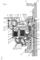
- the Figure 1 shows a first exemplary embodiment of a combination 1 of a torsional vibration damper T and a double clutch K1, K2 in a radially encompassing design in the axial half section.
- this combination of torsional shrinkage damper T and double clutch with the two nested individual clutches K1, K2 is referred to below as a double clutch device.
- the torsional vibration damper according to this drawing Figure 1 is basically designed in a conventional manner. It comprises a primary element 5 in the manner of a disk and a secondary element 6 with, in the present exemplary embodiment, 3 half-shells 7, 8, 9, 10, which are connected to one another in a rotationally fixed manner. Primary and secondary elements 5, 6 are coupled to one another via a spring device and can be rotated relative to one another about a neutral position.
- the spring device consists of a plurality of helical springs 14, 15 arranged one behind the other in the circumferential direction, which are spaced apart from one another with the aid of so-called sliding shoes, not shown here. There are coil springs 14, 15 with different spring diameters.
- a set of coil springs with a large diameter is provided with the reference number 14 in the exemplary embodiment, a set of coil springs with a small diameter is identified with the reference number 15 in the drawing figure.
- Each coil spring 14 with a large diameter is centrally penetrated by a coil spring 15 with a small diameter.
- Each pair of springs consisting of an outer coil spring 14 and an inner coil spring 15 connects at each end to one of the sliding shoes or end shoes, not shown here.
- Primary and secondary elements 5, 6 each comprise two drivers in a diametrical arrangement, which each engage between the chain consisting of coil springs 14, 15 running in the circumferential direction, so that a torque applied to the primary element 5 on the drive side is generated by means of a chain in the Figure 1
- Primary driver not shown, can first be transferred to the spring chain made of coil springs 14, 15 and from there to a secondary driver of the secondary element 6, also not shown.
- the secondary element 6 comprises three individual parts, namely a drive-side half-shell 9, an output-side half-shell 10 and a further half-shell 7, hereinafter referred to as the output-side secondary part element 7.
- the first two half-shells namely the drive-side half-shell 9 and the output-side half-shell 10 are designed in such a way that they accommodate the chain of coil springs 14, 15 in a substantially form-fitting manner.
- Both half-shells 9, 10 are connected to one another in a rotationally fixed manner via teeth 11.
- These two half-shells 9, 10 serve for preferably low-friction guidance of the springs 14, 15 or the sliding shoes and end shoes arranged between the pairs of springs 14, 15 in the circumferential direction.
- a further half-shell 7 is provided on the output side of the torsional vibration damper T.
- This half-shell 7 represents a coupling element for the components connected downstream of the torsional vibration damper T, i.e. in the present case for the double clutch K1, K2.
- the half-shell 7 is, similar to the half-shell 10, connected in a rotationally fixed manner to the drive-side half-shell 9 via a toothing 12. It extends over the half-shell 9 in the radially outer region. With the help of a locking ring 13 and a spring, not shown here, between the two half-shells 7, 10, the three half-shells 7, 9, 10 forming the secondary element 6 are axially resiliently fixed and connected.
- the double clutch in a radially nested arrangement is also constructed in a conventional manner. It includes a radially outer clutch K1 and a radially inner clutch K2.
- the radially outer clutch K1 comprises an outer disk carrier 30 and an inner disk carrier 32. Both disk carriers 30, 32 are designed in the manner of half-shells.
- the cylindrical part of the outer disk carrier 30 has teeth on the inner circumference. A corresponding one engages in each of these teeth External teeth in the present exemplary embodiment are designed as steel lamellas 36.
- the cylindrical part of the inner disk carrier 32 has a toothing on its outer circumference, into which a corresponding internal toothing of inner disks 37 designed here as lining disks engages.
- Outer disks 36 and inner disks 37 are inserted between the cylindrical regions of the outer and inner disk carriers 30, 32 in such a way that an inner disk 37 follows an outer disk 36 in the axial direction and vice versa.
- the outer and inner disks 36, 37 can be moved into and out of frictional engagement by means of an actuating piston 34.
- the radially inner clutch K2 is also designed in the same way as the radially outer multi-plate clutch K1.
- a half-shell-shaped outer disk carrier 31 and a half-shell-shaped inner disk carrier 33 are provided.
- the cylindrical part of the outer disk carrier 31 has teeth on the inner circumference, into which external teeth of corresponding outer disks 38 designed as steel disks engage.
- the cylindrical section of the inner disk carrier half-shell 33 has external teeth which can accommodate the internal teeth of corresponding inner disks 39.
- One inner disk 39 is arranged adjacent to two outer disks 38 and one outer disk 38 is arranged adjacent to an inner disk 39 to form a disk pack.
- the outer and inner disks 38, 39 can be brought into and out of frictional engagement with the aid of an actuating piston 35.
- the disk packs of the radially outer clutch K1 and the radially inner clutch K2 are arranged in a radially nested manner relative to one another. This means that the disk pack of the radially inner clutch K2 is located radially within the disk pack of the radially outer clutch K1 and in approximately the same axial section.
- the two outer disk carriers 30, 31 of the radially outer clutch K1 and the radially inner clutch K2 are connected to one another in a rotationally fixed manner via a clutch hub 49.
- This coupling hub 49 which essentially has the shape of a cylinder, is rotatably mounted on the outer circumference of a fixed carrier, which is generally referred to in technical language as a coupling support 22.
- the rotatable storage takes place via two radial needle bearings 25, 27.
- This standing support 22 is also essentially hollow cylindrical. It is penetrated by two coaxial transmission input shafts, which in the Figure 1 are not drawn, but their positions are identified by the two reference numbers 20 and 21.
- the primary element 5 of the torsional vibration damper T is rotatably mounted via a corresponding primary flange 4, which in turn is connected to the crankshaft 2 without axial play.
- storage is realized with the aid of a radial needle bearing 16.
- the two transmission input shafts namely the hollow shaft 21 and the solid shaft 20, are each connected in a rotationally fixed manner to one of the inner disk carriers 32, 33 of one of the two clutches K1, K2.
- the inner disk carriers 32, 33 have corresponding hubs 28, 29, which each have a plug-in toothing 51, 52 on the inner circumference for receiving corresponding toothings of the transmission input shafts 20, 21.
- the outer disk carrier 30 of the radially outer clutch K1 now represents the input side of the double clutch.
- the two inner disk carriers 32, 33 of the clutches K1, K2 form the output sides of the double clutch.
- a torque introduced via the outer disk carrier 30 can therefore, depending on the position of the two actuating pistons 34, 35, be transmitted to one of the two inner disk carriers 32, 33 and from there further via the corresponding hubs 28, 29 to the transmission input shafts 20, 21.
- the output-side secondary part element 7 is in this embodiment variant according to Figure 1 not only designed as a narrow ring with comparatively small radial dimensions, but the secondary part element 7 extends close to the outer radius of the hub 28. In this radially inner region, the output-side secondary part element 7 has a cylindrical shape. A radial needle bearing 26 is inserted between the inner circumference of this cylindrical section of the output-side secondary element 7 and the outer circumference of the inner disk carrier hub 28. This bearing point supports the secondary part element on the output side 7 radially and prevents a transfer of radial forces to the outer disk carrier 30 of the radially outer clutch K1 of the double clutch.
- the outer disk carrier 30 of the radially outer clutch K1 In order to keep any radial forces away from the double clutch, in particular the outer disk carrier 30 of the radially outer clutch K1, there is no rigid connection between the outer disk carrier 30 of the radially outer clutch K1 and the output-side secondary part element 7. Rather, the open end of the outer disk carrier 30 of the radially outer clutch points K1 has a toothing which engages with a corresponding toothing of the output-side secondary part element 7 with radial play.
- Axial needle bearings 41, 42 are provided between the sections of essentially radially extending inner disk carriers 32, 33 and the output-side secondary part element 7, which axially space the inner disk carriers 31, 32 and the output-side secondary part element 7.
- An axial needle bearing is also provided between the inner disk carrier 33 of the radially inner clutch K2 and a half-shell 53 connected in a rotationally fixed manner to the clutch support 22.
- axial needle bearings 40, 41, 42, 43 serve on the one hand for low-friction guidance of the mutually rotatable half-shells 33, 32, 7, 5 and for support in the axial direction, with the adjustment of the axial play using a locking ring 18 and a plate spring 19 the transfer point 17 of the torque from the torsional vibration damper T to the outer disk carrier 30 of the outer clutch K1 takes place.
- the exemplary embodiment shown shows that the invention can be easily implemented by using existing sheet metal parts, with the help of which the output-side secondary part element 7 is formed in the form of an additional cover.
- the inner area of the circuit board can be used to produce the necessary cover shape from an existing damper housing, which has previously been punched out to a large diameter and/or connected to the outer disk carrier of the outer clutch K1.
- the bearing point according to the invention can be designed to have almost no installation space.
- the invention makes it possible to adjust the overall clutch play independently of the damper play setting. This in turn enables the installation of damper designs that completely dispense with a play adjustment or whose primary side acts as a flex element, making the clutch damper unit independent of axial movements of the crankshaft.
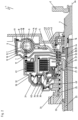
- the Figure 2 shows a further exemplary embodiment of a combination 1 according to the invention of a torsional vibration damper T and a double clutch K1, K2 in a radially nested arrangement in the axial half section.
- the entire dual clutch device 1 according to the Figure 2 is designed almost identically to the combination of torsional vibration damper T and double clutch K1, K2 according to Figure 1 . As far as the corresponding components are concerned, a further description is therefore omitted.
- the design variant according to the Figure 2 differs from that according to the Figure 1 only because there is no radial needle bearing 26 between the output-side secondary part element 7 and the hub 28 of the inner disk carrier 32 of the radially outer clutch K1. Rather, instead of this radial needle bearing 26, a radial needle bearing 44 is arranged between the outer circumference of the hollow cylindrical, radially inner end of the output-side secondary part element 7 and an inner circumference of the primary flange 4 of the primary element 5. Here too, radial forces introduced via the torsional vibration damper T are absorbed.
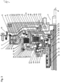
- the Figure 3 shows a third exemplary embodiment of a combination 1 according to the invention of a torsional vibration damper T and a double clutch K1, K2 in a radially nested arrangement in the axial half section.
- the torsional vibration damper T according to this drawing Figure 3 is basically designed in a conventional manner. It comprises a primary element 5 in the manner of a disk and a secondary element 6 with, in the present exemplary embodiment, two half-shells 7, 8, which are connected to one another in a rotationally fixed manner. Primary and secondary elements 5, 6 are coupled to one another via a spring device and can be rotated relative to one another about a neutral position.
- the spring device consists of a plurality of coil spring sets arranged one behind the other in the circumferential direction.
- a coil spring set consists of an inner spring 15 and an outer spring 15 surrounding it. Adjacent coil spring sets are spaced apart from one another with the help of sliding shoes 54, which are also referred to in technical language as spring dividers.
- Primary and secondary elements 5, 6 each comprise two drivers in a diametrical arrangement, which are each inserted between the chain of coil springs 14, 15 running in the circumferential direction, so that a torque coupled into the primary element 5 on the drive side is transmitted by means of one in each case Figure 1 shown primary driver 55 is first transferred to the spring chain consisting of the coil springs 14, 15 and from there to the respective corresponding secondary driver 56 of the secondary element 6.
- the two half-shells 7, 8, namely the drive-side half-shell 8 and the output-side half-shell 7, are designed in such a way that they accommodate the chain consisting of coil springs 14 in a substantially form-fitting manner.
- Both half-shells 9, 10 are connected to one another in a rotationally fixed manner via a toothing 11 and with the help of a circumferential groove on the output side Half shell 7 engaging locking ring 13 is secured against each other axially in a substantially immovable manner.
- These two half-shells 7, 8 serve to guide the springs 14, 15 or the sliding shoes 55 arranged between the springs 14, 15 in the circumferential direction, preferably with low friction.
- the double clutch itself in a radially nested arrangement is also constructed in a conventional manner. It comprises two clutches K1, K2, with the disk pack of one clutch K2 being arranged radially within the disk pack of the other clutch K1. In addition, both disk packs are arranged in approximately the same axial section.
- the clutch K1 with the radially outer disk pack is hereinafter referred to as the radially outer disk clutch K1, the other as the radially inner disk clutch K2.
- the radially outer clutch K1 comprises an outer disk carrier 30 and an inner disk carrier 32. Both disk carriers 30, 32 are designed in the manner of half-shells.
- the cylindrical part 57 of the outer disk carrier 30 has teeth 58 on the inner circumference. This toothing 58 engages with a corresponding external toothing 59 of outer disks 36, which in the present exemplary embodiment are designed as steel disks.
- the cylindrical part 60 of the inner disk carrier 32 has a toothing 61 on the outer circumference, into which a corresponding internal toothing 62 of inner disks 37 designed here as lining disks engages.
- Outer disks 36 and inner disks 37 are inserted between the cylindrical regions 57, 60 of the outer and inner disk carriers 30, 32 in such a way that an inner disk 37 follows an outer disk 36 in the axial direction and vice versa.
- the outer and inner disks 36, 37 can be moved into and out of frictional engagement by means of an actuating piston 34.
- the radially inner clutch K2 is in principle designed in the same way as the radially outer multi-plate clutch K1.
- a half-shell-shaped outer disk carrier 31 and a half-shell-shaped inner disk carrier 33 are provided.
- the cylindrical part 63 of the half-shell-shaped outer disk carrier 31 has a toothing 64 on the inner circumference, into which an external toothing 65 of corresponding outer disks 38 designed as steel disks engages.
- the cylindrical section 66 of the inner disk carrier half-shell 33 has external teeth 67, which receive the internal teeth 68 of corresponding inner disks 39.
- An inner disk 39 is hereby arranged adjacent to two outer disks 38, an outer disk 38 is arranged adjacent to two inner disks 39 to form a disk pack. The outer and inner disks 38, 39 can be brought into and out of frictional engagement with the aid of an actuating piston 35.
- the outer disk carrier 31 of the radially inner clutch K2 is connected to a clutch hub 49 in a rotationally fixed manner. Furthermore, there is a rotationally fixed connection between the outer disk carrier 30 of the radially outer clutch K1 and a side disk 48 which is welded to the clutch hub 49 and carries a pump drive gear 24 with the aid of a spline 17.
- the clutch hub 49 which essentially has the shape of a cylinder, is about a Axis of rotation ax is rotatably mounted on the outer circumference of a transmission input shaft 21. The rotatable storage takes place via two radial needle bearings 25, 27.
- the transmission input shaft 21 is designed in the form of a hollow cylinder. It is centrally penetrated by another transmission input shaft 22 designed as a solid shaft and is rotatably mounted on it by means of a radial needle bearing 50.
- the hollow shaft 21 is connected via a spline 51 to a hub 29 of the inner disk carrier 33 of the radially inner clutch K2.
- the solid shaft 20 is connected in a rotationally fixed manner via a spline 52 to a hub 28 of the inner disk carrier 32 of the radially outer disk clutch K1.
- a torque introduced into the outer disk carrier 30 via or the clutch hub 49 is therefore selectively transmitted to one of the two transmission input shafts 20, 21 via one of the two inner disk carriers 31 or 33, depending on the position of the two actuating pistons 34, 35.
- the input side of the double clutch K1, K2 and the output side of the torsional vibration damper T are rigidly connected to one another via a weld seam 47 between the output-side secondary part element 7 and the cylindrical part 57 of the outer disk carrier 30 of the radially outer clutch K1. Furthermore, there is a rotationally fixed connection between a primary hub 4 of the primary element 5 and an input flywheel 46 via a spline 69. The input flywheel 46 in turn is connected on the input side to a crankshaft 2, which can be driven by an internal combustion engine, not shown here.
- the clutch play is adjusted via a locking ring 18 and a disc spring 19 on the outer edge of the double clutch.
- the axial displaceability is determined radially on the inside by two axial needle bearings 42, 43, which are arranged between the inner disk carrier 33 of the inner clutch K2, the inner disk carrier 32 of the radially outer clutch K1 and the outer disk carrier 30 of the radially outer clutch K1.
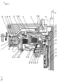
- the Figure 4 shows a fourth exemplary embodiment of a combination 1 according to the invention of torsional vibration damper T and double clutch K1, K2. This embodiment variant is very similar to the coupling device according to the Figure 3 executed. A further description of matching components is therefore omitted.
- the torque transfer point from the torsional vibration damper T to the double clutch K1, K2 is not on a weld seam 47 between the output-side half-shell 10 of the secondary element 6 and the outer disk carrier 30, but on the toothing 17.
- the side window 48 is a further output-side secondary part element similar to that to the Figures 1 and 2 described type.
- the radial deposition does not take place via an output-side half-shell 10 of the secondary element 6, which is partly formed by the outer disk carrier 30, as in the embodiment variant according to Figure 3 , but via the drive-side half-shell 8, which for this purpose is designed to extend radially inwards, opens into a cylindrical section and in this area connects on the inside circumference to a radial needle bearing 45, which sits on the outer circumference of the hub 28 of the inner disk carrier 32 of the radially outer clutch .
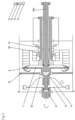
- Figure 5 shows part of a crankshaft 75 on the drive side, which carries a flywheel 76.
- the shaft 77 which forms the extension of the crankshaft 75, is mounted radially in a first floating bearing 78 on the gear cover 79 and on the other hand on the gear shaft 80a.
- the shaft/primary flange 77 carries the primary element 7 of the torsional vibration damper.
- the shaft 77 and the primary part 7 are not supported in the axial direction, but are subject to the axial movements that are imposed by the crankshaft, to which they are coupled axially without play.
- the primary part 7 has an axial play within the half-shells, which form parts of the secondary part 8, so that corresponding axial movements of the crankshaft can be accommodated here.
- the secondary element 8 of the torsional vibration damper is in turn mounted radially via the output-side coupling, for example in the bearings 80, 81.
- the individual sections of the drive chain i.e. the crankshaft 75, the shaft 77 and the primary element 7 of the torsional vibration damper, are connected to one another without play in the axial direction, for example by welding, shrinking or screwing, so that a relative movement of these parts against one another is avoided and, as a result, no noise or imbalances can occur.
- the radial mounting of the shaft 77 and thus the primary element 7 of the torsional vibration damper in the bearing 78 on the gear cover 79 also causes the drive elements to run precisely in the radial direction and thus avoids corresponding imbalances or irregularities in the transmission of the rotary movement within the torsional vibration damper.
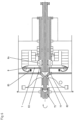
- the Figure 6 shows in addition and as an alternative to the construction in Figure 5 It is shown that the shaft 77 is mounted in a fixed bearing 82 and that the shaft/primary flange 77 is additionally axially supported in the bearings 83, 84 relative to the parts of the coupling. It is important for the functioning of the invention that the axial play of the bearings 83, 84 is greater than the expected axial movements of the crankshaft 75. Corresponding movements of the primary element 7 can then be absorbed by the axial play relative to the secondary element 8 in the torsional vibration damper.
- the secondary element 8 of the torsional vibration damper is additionally supported relative to the primary element 7 by means of a radial bearing 85.
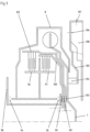
- Figure 7 shows a bearing of the secondary element 8 via the drive-side half-shell 86 and its radially inwardly extending extension with a radial bearing 87 on the gear cover 79.
- the figure also shows the axial play 88 between the primary element 7 and the half-shells 86, 89 of the secondary element and the output-side coupling 90.
- Figure 8 shows a part of a shaft 77 connected to the crankshaft, to which the primary part 7 is firmly attached.
- the shaft 77 is mounted radially relative to a gear shaft 91.
- An axial storage of the primary element 7 is not provided.
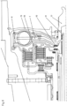
- FIG. 9 shows a schematic overview of possible axial bearing points of the entire arrangement, namely in the axial bearings 94, 95, which support the inner disk carriers 96, 97 radially relative to a clutch carrier 98, as well as the axial bearing 99, which axially supports a first outer disk carrier 100 relative to the clutch carrier 98, and an axial bearing 101 for axial support between the outer disk carrier 100 and a further outer disk carrier 102.
- an axial bearing 103 is provided for supporting the primary element 7 relative to the outer disk carrier 102.
- the primary element 7 is joined together by a weld or screw connection with a torsional vibration damper hub 104, which in turn is connected to a flex plate 105.
- the flex plate 105 is connected to a flywheel 108 by means of a screw connection 106 with axial screws and/or a radial screw connection 107. Elongated holes can be provided in the screw connection 106, 107, which allow the tolerance compensation between the primary element 7 and the flex plate, the flywheel and the crankshaft to be adjusted.
Landscapes
- Engineering & Computer Science (AREA)
- General Engineering & Computer Science (AREA)
- Mechanical Engineering (AREA)
- Physics & Mathematics (AREA)
- Acoustics & Sound (AREA)
- Aviation & Aerospace Engineering (AREA)
- Mechanical Operated Clutches (AREA)
- Hydraulic Clutches, Magnetic Clutches, Fluid Clutches, And Fluid Joints (AREA)
Applications Claiming Priority (3)
| Application Number | Priority Date | Filing Date | Title |
|---|---|---|---|
| DE102005053073 | 2005-11-04 | ||
| DE102006003955 | 2006-01-26 | ||
| PCT/EP2006/010538 WO2007051627A1 (de) | 2005-11-04 | 2006-11-02 | Torsionsschwingungsdämpfer mit einer ankopplung an eine kurbelwelle sowie kombination aus einem torsionsschwingungsdämpfer und einer kupplung |
Publications (4)
| Publication Number | Publication Date |
|---|---|
| EP1943437A1 EP1943437A1 (de) | 2008-07-16 |
| EP1943437B1 EP1943437B1 (de) | 2019-06-19 |
| EP1943437B8 EP1943437B8 (de) | 2019-09-11 |
| EP1943437B2 true EP1943437B2 (de) | 2023-09-20 |
Family
ID=37808161
Family Applications (1)
| Application Number | Title | Priority Date | Filing Date |
|---|---|---|---|
| EP06828913.1A Active EP1943437B2 (de) | 2005-11-04 | 2006-11-02 | Kombination aus einem torsionsschwingungsdämpfer mit einer kurbelwelle |
Country Status (6)
| Country | Link |
|---|---|
| US (1) | US20080283330A1 (ja) |
| EP (1) | EP1943437B2 (ja) |
| JP (1) | JP5155174B2 (ja) |
| KR (1) | KR101264915B1 (ja) |
| CN (1) | CN101300435B (ja) |
| WO (1) | WO2007051627A1 (ja) |
Families Citing this family (19)
| Publication number | Priority date | Publication date | Assignee | Title |
|---|---|---|---|---|
| DE102008008062B4 (de) | 2008-02-01 | 2014-05-22 | Getrag Getriebe- Und Zahnradfabrik Hermann Hagenmeyer Gmbh & Cie Kg | Doppelkupplungsanordnung |
| US9080636B2 (en) * | 2008-06-16 | 2015-07-14 | Schaeffler Technologies AG & Co. KG | Dual clutch with torsional vibration damper |
| DE102008063385B4 (de) | 2008-12-30 | 2013-08-14 | Getrag Ford Transmissions Gmbh | Kupplungssupport |
| WO2010081452A1 (de) * | 2009-01-19 | 2010-07-22 | Luk Lamellen Und Kupplungsbau Beteiligungs Kg | Kupplungsaggregat mit drehschwingungsdämpfer |
| WO2010081455A1 (de) † | 2009-01-19 | 2010-07-22 | Luk Lamellen Und Kupplungsbau Beteiligungs Kg | Kupplungsaggregat |
| DE102009042682A1 (de) * | 2009-09-23 | 2011-03-24 | Man Nutzfahrzeuge Ag | Antriebsvorrichtung für zumindest einen Nebentrieb |
| WO2011063796A1 (de) * | 2009-11-24 | 2011-06-03 | Schaeffler Technologies Gmbh & Co. Kg | Drehmomentübertragungseinrichtung |
| DE102010032534B4 (de) * | 2010-07-28 | 2019-09-12 | Borgwarner Inc. | Torsionsschwingungsdämpfer und Kupplungseinrichtung mit einem Filtermedium innerhalb des Nassraums |
| JP5585566B2 (ja) * | 2011-03-30 | 2014-09-10 | アイシン・エィ・ダブリュ株式会社 | 変速装置 |
| KR101251232B1 (ko) * | 2011-04-15 | 2013-04-08 | 주식회사평화발레오 | 작동 하중에 대한 민감도가 감소된 건식 더블클러치 |
| DE102012223950B4 (de) | 2012-01-20 | 2018-10-25 | Schaeffler Technologies AG & Co. KG | Übertragungseinheit mit integriertem Dämpfersystem |
| DE112015003929A5 (de) * | 2014-08-29 | 2017-06-22 | Schaeffler Technologies AG & Co. KG | Doppelkupplung |
| CN109154335B (zh) * | 2016-03-30 | 2020-05-08 | 本田技研工业株式会社 | 动力传递装置 |
| DE102016010482A1 (de) * | 2016-08-31 | 2018-03-01 | Borgwarner Inc. | Drehmomentübertragunasvorrichtung für den Antriebsstrang eines Kraftfahrzeugs und Antriebsstrang mit einer solchen Drehmomentübertragungsvorrichtung |
| CN107054046A (zh) * | 2016-12-21 | 2017-08-18 | 重庆长安汽车股份有限公司 | 一种混合动力耦合机构与双离合变速器导向连接结构 |
| JP6539687B2 (ja) * | 2017-03-15 | 2019-07-03 | 本田技研工業株式会社 | 動力伝達装置 |
| DE102018120260A1 (de) * | 2018-08-21 | 2020-02-27 | Schaeffler Technologies AG & Co. KG | Drehschwingungsdämpfer |
| DE102021200819A1 (de) * | 2021-01-29 | 2022-08-04 | Zf Friedrichshafen Ag | Torsionsschwingungsdämpfer für einen Fahrzeugantriebsstrang |
| DE102021003253A1 (de) | 2021-06-24 | 2022-12-29 | BorgWarner lnc. | Doppelkupplungseinrichtung |
Citations (1)
| Publication number | Priority date | Publication date | Assignee | Title |
|---|---|---|---|---|
| DE10118821A1 (de) † | 2001-04-17 | 2002-10-24 | Zf Sachs Ag | Torsionsschwingungsdämpfer |
Family Cites Families (23)
| Publication number | Priority date | Publication date | Assignee | Title |
|---|---|---|---|---|
| JPS60136621A (ja) * | 1983-11-10 | 1985-07-20 | ル−ク・ラメレン・ウント・クツプルングスバウ・ゲゼルシヤフト・ミツト・ベシユレンクテル・ハフツング | 回転衝撃を受容又は補償するための緩衝装置 |
| DE3411090A1 (de) * | 1983-11-10 | 1985-05-23 | LuK Lamellen und Kupplungsbau GmbH, 7580 Bühl | Daempfungseinrichtung zum aufnehmen bzw. ausgleichen von drehstoessen |
| DE3427163A1 (de) * | 1984-07-24 | 1986-04-03 | LuK Lamellen und Kupplungsbau GmbH, 7580 Bühl | Einrichtung zum kompensieren von drehstoessen |
| US5209330A (en) * | 1991-12-23 | 1993-05-11 | Ford Motor Company | Slipping bypass clutch for hydrokinetic torque converter |
| DE19522718B4 (de) * | 1994-07-01 | 2009-07-30 | Luk Lamellen Und Kupplungsbau Beteiligungs Kg | Torsionsschwingungsdämpfer |
| US5964328A (en) * | 1997-07-09 | 1999-10-12 | Ford Global Techologies, Inc. | Torque converter bypass clutch having a modular spring damper arrangement |
| DE19921687C5 (de) * | 1999-05-12 | 2016-06-09 | Borgwarner Inc. | Mehrfach-Kupplungssystem für ein Getriebe |
| DE19957978B4 (de) | 1999-12-02 | 2008-04-17 | Audi Ag | Anordnung und Lagerung eines Zweimassenschwungrades |
| JP3664629B2 (ja) * | 2000-03-09 | 2005-06-29 | 株式会社エクセディ | 流体式トルク伝達装置 |
| JP3907372B2 (ja) * | 2000-03-22 | 2007-04-18 | 株式会社エクセディ | クラッチ装置 |
| DE10133693B4 (de) * | 2000-07-27 | 2016-03-24 | Schaeffler Technologies AG & Co. KG | Torsionsschwingungsdämpfer |
| JP5023372B2 (ja) * | 2000-11-22 | 2012-09-12 | シェフラー テクノロジーズ アクチエンゲゼルシャフト ウント コンパニー コマンディートゲゼルシャフト | クラッチ装置 |
| DE10153839A1 (de) | 2001-11-05 | 2003-05-28 | Voith Turbo Kg | Kombinierte Schwungrad-Dämpfungseinheit |
| DE10223780C1 (de) | 2002-05-29 | 2003-10-16 | Porsche Ag | Gangschaltgetriebe für ein Kraftfahrzeug mit hydraulisch betätigbarer Mehrfachkupplung |
| DE50206194D1 (de) * | 2002-06-15 | 2006-05-18 | Borgwarner Inc | Vorrichtung zur Dämpfung von Drehschwingungen |
| DE102004015214A1 (de) * | 2003-04-04 | 2004-10-21 | Luk Lamellen Und Kupplungsbau Beteiligungs Kg | Mehrfachkupplungsaggregat |
| JP2004003678A (ja) * | 2003-07-31 | 2004-01-08 | Exedy Corp | 動力伝達装置 |
| FR2858674B1 (fr) * | 2003-08-04 | 2007-06-29 | Valeo Embrayages | Double volant amortisseur a volant primaire flexible |
| EP1522752A1 (de) * | 2003-10-11 | 2005-04-13 | BorgWarner Inc. | Antriebsstrang |
| EP1548313B2 (de) * | 2003-12-23 | 2016-09-28 | Schaeffler Technologies AG & Co. KG | Drehmomentübertragungseinrichtung |
| DE502005005856D1 (de) * | 2004-06-21 | 2008-12-18 | Luk Lamellen & Kupplungsbau | Drehmomentübertragungseinrichtung |
| ATE419477T1 (de) * | 2004-06-21 | 2009-01-15 | Luk Lamellen & Kupplungsbau | Drehmomentübertragungseinrichtung |
| DE502005007567D1 (de) | 2005-05-25 | 2009-08-06 | Borgwarner Inc | Kombination aus einem Torsionsschwingungsdämpfer und einer Kupplung |
-
2006
- 2006-11-02 WO PCT/EP2006/010538 patent/WO2007051627A1/de active Application Filing
- 2006-11-02 EP EP06828913.1A patent/EP1943437B2/de active Active
- 2006-11-02 JP JP2008538305A patent/JP5155174B2/ja not_active Expired - Fee Related
- 2006-11-02 US US12/092,421 patent/US20080283330A1/en not_active Abandoned
- 2006-11-02 CN CN2006800410705A patent/CN101300435B/zh not_active Expired - Fee Related
-
2008
- 2008-04-22 KR KR1020087009635A patent/KR101264915B1/ko active IP Right Grant
Patent Citations (1)
| Publication number | Priority date | Publication date | Assignee | Title |
|---|---|---|---|---|
| DE10118821A1 (de) † | 2001-04-17 | 2002-10-24 | Zf Sachs Ag | Torsionsschwingungsdämpfer |
Also Published As
| Publication number | Publication date |
|---|---|
| KR20080064126A (ko) | 2008-07-08 |
| JP5155174B2 (ja) | 2013-02-27 |
| EP1943437A1 (de) | 2008-07-16 |
| JP2009515102A (ja) | 2009-04-09 |
| CN101300435A (zh) | 2008-11-05 |
| WO2007051627A1 (de) | 2007-05-10 |
| EP1943437B1 (de) | 2019-06-19 |
| KR101264915B1 (ko) | 2013-05-15 |
| CN101300435B (zh) | 2011-11-23 |
| US20080283330A1 (en) | 2008-11-20 |
| EP1943437B8 (de) | 2019-09-11 |
Similar Documents
| Publication | Publication Date | Title |
|---|---|---|
| EP1943437B2 (de) | Kombination aus einem torsionsschwingungsdämpfer mit einer kurbelwelle | |
| EP2109722B1 (de) | Drehmomentübertragungseinrichtung | |
| EP1751444B1 (de) | Kupplungseinrichtung , insbesondere doppelkupplungseinrichtung, mit einer einrichtung zur axialen positionierung der kupplungseinrichtung | |
| EP1941171B2 (de) | Kopplungseinrichtung zur übertragung eines drehmoments | |
| DE19544832C2 (de) | Kupplung | |
| EP1464873A2 (de) | Torsionsschwingungsdämpfer für Drehmomentwandler | |
| EP1840400B1 (de) | Kupplungsvorrichtung mit einer Kupplung und einem damit verbundenen Drehschwingungsdämpfer sowie Getriebe mit einer solchen Kupplungsvorrichtung | |
| DE112015000319T5 (de) | Dämpfervorrichtung | |
| DE102014209833A1 (de) | Lageanordnung für eine Zwischenwelle in einer Trennkupplung für ein Hybridmodul mit getrennter axialer und radialer Lagerung | |
| EP2899426A1 (de) | Drehschwingungsdämpfer | |
| DE102016220567A1 (de) | Drehschwingungsdämpferaggregat | |
| EP1726847B1 (de) | Kombination aus einem Torsionsschwingungsdämpfer und einer Kupplung | |
| DE112015000321T5 (de) | Dämpfervorrichtung und Startvorrichtung | |
| EP2097657A1 (de) | Torsionsschwingungsdämpfer mit mehrteiligem primärelement | |
| WO2018068781A1 (de) | Kupplungsscheibe, reibungskupplungseinrichtung und antriebsstrang | |
| EP2769117B1 (de) | Drehschwingungsdämpfungsanordnung, insbesondere für den antriebsstrang eines fahrzeugs | |
| DE112018005564T5 (de) | Schnittstellenmodul für einen antriebsstrang | |
| DE69822008T2 (de) | Übertragungskupplungseinheit | |
| DE102012219800B4 (de) | Drehschwingsdämpfer und Kupplungsaggregat | |
| EP1614919B1 (de) | Kupplungsanordnung | |
| DE102011103495A1 (de) | Kupplungswelle,Aktor,Nockenwellenverstellgetriebe und Nockenwellensteller | |
| DE19820503B4 (de) | Torsionsschwingungsdämpfer mit zumindest einer Lagerung zwischen Dämpferelementen | |
| DE102019104081A1 (de) | Kupplungsaggregat | |
| WO2015139912A1 (de) | Drehschwingungsdämpfungsanordnung für den antriebsstrang eines fahrzeugs | |
| DE19841495A1 (de) | Vorrichtung zur Drehmomentübertragung und zur Torsionsdämpfung mit einem Torsionsdämpfer |
Legal Events
| Date | Code | Title | Description |
|---|---|---|---|
| PUAI | Public reference made under article 153(3) epc to a published international application that has entered the european phase |
Free format text: ORIGINAL CODE: 0009012 |
|
| 17P | Request for examination filed |
Effective date: 20080523 |
|
| AK | Designated contracting states |
Kind code of ref document: A1 Designated state(s): DE FR IT |
|
| RIN1 | Information on inventor provided before grant (corrected) |
Inventor name: BOELLING, JOCHEN Inventor name: HEINZ, VOLKER Inventor name: EBNER, TILL Inventor name: STRAUSS, DIETMAR, ERNST Inventor name: HALM, CHRISTIAN |
|
| RIN1 | Information on inventor provided before grant (corrected) |
Inventor name: HEINZ, VOLKER Inventor name: STRAUSS, DIETMAR, ERNST Inventor name: BOELLING, JOCHEN Inventor name: EBNER, TILL MARTIN LUTZ Inventor name: HALM, CHRISTIAN |
|
| DAX | Request for extension of the european patent (deleted) | ||
| RBV | Designated contracting states (corrected) |
Designated state(s): DE FR IT |
|
| 17Q | First examination report despatched |
Effective date: 20151110 |
|
| STAA | Information on the status of an ep patent application or granted ep patent |
Free format text: STATUS: EXAMINATION IS IN PROGRESS |
|
| GRAP | Despatch of communication of intention to grant a patent |
Free format text: ORIGINAL CODE: EPIDOSNIGR1 |
|
| STAA | Information on the status of an ep patent application or granted ep patent |
Free format text: STATUS: GRANT OF PATENT IS INTENDED |
|
| INTG | Intention to grant announced |
Effective date: 20190122 |
|
| GRAS | Grant fee paid |
Free format text: ORIGINAL CODE: EPIDOSNIGR3 |
|
| GRAA | (expected) grant |
Free format text: ORIGINAL CODE: 0009210 |
|
| STAA | Information on the status of an ep patent application or granted ep patent |
Free format text: STATUS: THE PATENT HAS BEEN GRANTED |
|
| AK | Designated contracting states |
Kind code of ref document: B1 Designated state(s): DE FR IT |
|
| REG | Reference to a national code |
Ref country code: DE Ref legal event code: R096 Ref document number: 502006016283 Country of ref document: DE |
|
| GRAT | Correction requested after decision to grant or after decision to maintain patent in amended form |
Free format text: ORIGINAL CODE: EPIDOSNCDEC |
|
| RBV | Designated contracting states (corrected) |
Designated state(s): DE |
|
| REG | Reference to a national code |
Ref country code: DE Ref legal event code: R026 Ref document number: 502006016283 Country of ref document: DE |
|
| PLBI | Opposition filed |
Free format text: ORIGINAL CODE: 0009260 |
|
| 26 | Opposition filed |
Opponent name: ZF FRIEDRICHSHAFEN AG Effective date: 20200317 |
|
| PLAX | Notice of opposition and request to file observation + time limit sent |
Free format text: ORIGINAL CODE: EPIDOSNOBS2 |
|
| PLBB | Reply of patent proprietor to notice(s) of opposition received |
Free format text: ORIGINAL CODE: EPIDOSNOBS3 |
|
| PLAB | Opposition data, opponent's data or that of the opponent's representative modified |
Free format text: ORIGINAL CODE: 0009299OPPO |
|
| R26 | Opposition filed (corrected) |
Opponent name: ZF FRIEDRICHSHAFEN AG Effective date: 20200317 |
|
| P01 | Opt-out of the competence of the unified patent court (upc) registered |
Effective date: 20230327 |
|
| PUAH | Patent maintained in amended form |
Free format text: ORIGINAL CODE: 0009272 |
|
| STAA | Information on the status of an ep patent application or granted ep patent |
Free format text: STATUS: PATENT MAINTAINED AS AMENDED |
|
| 27A | Patent maintained in amended form |
Effective date: 20230920 |
|
| AK | Designated contracting states |
Kind code of ref document: B2 Designated state(s): DE |
|
| REG | Reference to a national code |
Ref country code: DE Ref legal event code: R102 Ref document number: 502006016283 Country of ref document: DE |
|
| PGFP | Annual fee paid to national office [announced via postgrant information from national office to epo] |
Ref country code: DE Payment date: 20231010 Year of fee payment: 18 |