EP1941815A2 - Dispositif de direction couplée au mouvement pour une partie de siège, en particulier d'une chaise - Google Patents
Dispositif de direction couplée au mouvement pour une partie de siège, en particulier d'une chaise Download PDFInfo
- Publication number
- EP1941815A2 EP1941815A2 EP08000107A EP08000107A EP1941815A2 EP 1941815 A2 EP1941815 A2 EP 1941815A2 EP 08000107 A EP08000107 A EP 08000107A EP 08000107 A EP08000107 A EP 08000107A EP 1941815 A2 EP1941815 A2 EP 1941815A2
- Authority
- EP
- European Patent Office
- Prior art keywords
- seat part
- servo device
- motion
- elements
- support frame
- Prior art date
- Legal status (The legal status is an assumption and is not a legal conclusion. Google has not performed a legal analysis and makes no representation as to the accuracy of the status listed.)
- Granted
Links
Images


Classifications
-
- A—HUMAN NECESSITIES
- A47—FURNITURE; DOMESTIC ARTICLES OR APPLIANCES; COFFEE MILLS; SPICE MILLS; SUCTION CLEANERS IN GENERAL
- A47C—CHAIRS; SOFAS; BEDS
- A47C1/00—Chairs adapted for special purposes
- A47C1/02—Reclining or easy chairs
- A47C1/031—Reclining or easy chairs having coupled concurrently adjustable supporting parts
- A47C1/032—Reclining or easy chairs having coupled concurrently adjustable supporting parts the parts being movably-coupled seat and back-rest
- A47C1/03255—Reclining or easy chairs having coupled concurrently adjustable supporting parts the parts being movably-coupled seat and back-rest with a central column, e.g. rocking office chairs
-
- A—HUMAN NECESSITIES
- A47—FURNITURE; DOMESTIC ARTICLES OR APPLIANCES; COFFEE MILLS; SPICE MILLS; SUCTION CLEANERS IN GENERAL
- A47C—CHAIRS; SOFAS; BEDS
- A47C1/00—Chairs adapted for special purposes
- A47C1/02—Reclining or easy chairs
- A47C1/031—Reclining or easy chairs having coupled concurrently adjustable supporting parts
- A47C1/032—Reclining or easy chairs having coupled concurrently adjustable supporting parts the parts being movably-coupled seat and back-rest
- A47C1/03261—Reclining or easy chairs having coupled concurrently adjustable supporting parts the parts being movably-coupled seat and back-rest characterised by elastic means
- A47C1/03272—Reclining or easy chairs having coupled concurrently adjustable supporting parts the parts being movably-coupled seat and back-rest characterised by elastic means with coil springs
-
- A—HUMAN NECESSITIES
- A47—FURNITURE; DOMESTIC ARTICLES OR APPLIANCES; COFFEE MILLS; SPICE MILLS; SUCTION CLEANERS IN GENERAL
- A47C—CHAIRS; SOFAS; BEDS
- A47C1/00—Chairs adapted for special purposes
- A47C1/02—Reclining or easy chairs
- A47C1/031—Reclining or easy chairs having coupled concurrently adjustable supporting parts
- A47C1/032—Reclining or easy chairs having coupled concurrently adjustable supporting parts the parts being movably-coupled seat and back-rest
- A47C1/03294—Reclining or easy chairs having coupled concurrently adjustable supporting parts the parts being movably-coupled seat and back-rest slidingly movable in the base frame, e.g. by rollers
Definitions
- the invention relates to a motion-coupled servo device for a seat part, in particular a chair, such as an office or work chair.
- a chair in particular an office chair or work chair is known, which has a seat part, which is synchronously tiltable longitudinally displaceable on a support frame and possibly forcibly guided relative to a starting from a rest position in a plurality of inclination positions backrest.
- a feedback device which is connected on the one hand with the free end of a support arm of the support frame and on the other hand with the seat part.
- This feedback device can transmit feedback loads to the seat part and / or the backrest part in a largely lossless manner.
- a gas spring device As an example of a feedback device, there is schematically shown a gas spring device.
- a gas spring device takes up a relatively large amount of installation space and is relatively expensive. Also arise difficulties in the most uniform counterforce generation in the movement of the seat part and backrest part.
- the invention therefore aims to provide a motion-coupled servo device for a seat part, in particular a chair, such as an office or work chair of the type mentioned, which in the most space-saving and weight-saving and cost-saving manner when using a mechanical spring device despite their progressive behavior allowed as even as possible Gegenkraftbeetzschlagung and allowed the most uniform movement of the seat part and backrest part in the longitudinal sliding movement relative to a support frame of such a chair.
- a motion-coupled servo device for a seat part in particular a chair, provided for this purpose, which is synchronously tiltable longitudinally displaceable and optionally with respect to a starting from a rest position tiltable in several tilt positions backrest part on a support frame, wherein the servo device on the one hand with the Supporting frame and on the other hand is connected to the seat part, and wherein the motion-coupled servo device is characterized in that the servo device is designed as a multi-lever elements comprehensive, scissors-shaped articulated lever assembly with progressive Federkraftbeetzschung such that in each position of the seat part by the relative angular changes of the toggle elements to each other approximately constant power transmission to the seat part and takes place at a relatively large L jossverschiebungsweg the seat part a short travel in the Federkraftschlagung results.
- the provided according to the invention motion-coupled servo device for a seat part in such a chair is designed relatively flat construction thanks to the multiple articulated lever elements comprehensive, scissor-type articulated lever assembly and can be arranged in a simple manner to save space below the seat part.
- the Federkraftbeetzschung and the approximately constant power transmission to the seat part by means of the scissor-type articulated lever arrangement is also achieved that the seat part moves as smoothly and smoothly as possible during its longitudinal sliding movement when a person takes place on the seat part and by appropriate body movements, the seat part and / or Adjust the backrest part in the desired inclination position.
- the motion-coupled servo device according to the invention Since, due to the inventive design of the motion-coupled servo device is an approximately constant force transmission to the seat part, in each position of the seat part, the motion-coupled servo device according to the invention operates with substantially constant loading in all L jossverschiebungsfesten the seat part with respect to the support frame. This also improves the Ease of use, since the motion-coupled servo device according to the invention automatically ensures a guide and return of the seat part and / or the tiltable backrest part.
- the articulated lever assembly of the motion-coupled servo device comprises at least four toggle elements.
- the toggle assembly is designed substantially symmetrically to a line passing through the connection points with the seat portion and the support frame.
- the articulated lever assembly of the motion-coupled servo device comprises two first, intersecting and pivotally interconnected at the intersection articulated joint elements, whose ends are rotatably mounted with respect to a support frame fixed support shaft and acted upon by a spring means, and their other ends, each having one end are connected by at least two further second toggle elements whose other ends are connected at a common pivot bearing point with the seat part.
- this articulated lever assembly includes to achieve this approximately constant power transmission to the seat part exclusively mechanical elements free of gaseous or liquid media. This gives a reliable operation of the motion-coupled servo device with substantially constant properties according to the invention.
- the support frame fixed support shaft for the pivotal mounting of the ends of the first toggle lever elements is aligned substantially perpendicular to the longitudinal displacement direction of the seat part. This allows the available below the seat part space in a very favorable manner for the Arrangement of the motion-coupled servo device can be used according to the invention.
- a spring element in particular a spiral spring element, is assigned to each end of the first articulated lifting elements on the pivot bearing on the support frame fixed to the suspension spring.
- the spring elements act evenly on the respective ends of the first toggle elements and gives a substantially uniform application of force by the spring elements.
- each spring element is compressed in the longitudinal displacement of the seat part from the rest position.
- the spring elements are used in the longitudinal displacement of the seat part from the rest position as energy storage, whereby optionally in an oppositely directed movement of the seat part by this spring force of the spring elements, an automatic return and provision can be achieved.
- the support frame fixed support shaft of the toggle lever assembly is arranged on a substantially perpendicular to a horizontal leg of the support frame extending support arm. This results in a largely central arrangement of the toggle lever arrangement based on the width extension of the seat part.
- a locking device for the movement limitation of the seat part and / or backrest part is provided in predeterminable backrest part inclination positions.
- This locking device allows the arrangement of the seat part and the backrest part to be optionally forcibly blocked in predetermined and preselected positions with respect to movement, so that the user of the chair can optionally set and display preselected setting positions as desired.
- the toggle elements may be at least partially arcuate curved. This gives a shapely interpretation of the toggle elements, which further also no protruding sharp edges, especially on the sides and ends of the lever elements, which could possibly lead to injury.
- the spring device in the motion-coupled servo device according to the invention is designed such that it applies corresponding counterforces for variable body weights by variable bias.
- variable bias a vote is made to different body weights of the persons who use the chair.
- an adaptation to different body weights of the user person is realized by means of constructive means.
- a motion-coupled servo device for a seat part is specified according to the invention, which allows the smoothest possible and smooth entrainment of the seat part and / or the backrest part at the respective different positions.
- the servo device also serves as a return device and comprises a spring accumulator which serves as an energy storage according to the longitudinal movement of the seat part, which then ensures a substantially constant force transmission to the seat part in any position of the seat part with a corresponding counter-movement by relaxation.
- the motion-coupled servo device for a seat part according to the invention combines both a Federkraftbeetzschung in the longitudinal movement and a power storage function with additional feedback properties.
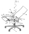
- FIGS. 1 and 2 the components of the basic construction will be explained in more detail with reference to an embodiment in the form of an office chair generally designated 1, which in the DE 10 306 851 shown and described which EP 1 596 691 B1 equivalent.
- FIG. 1 is a pedestal 2, for example in the form of Primafußgestells, centered on a columnar part 3, which may include, for example, a gas spring or the like for height adjustment of the chair, fußgestallemittig rotatably connected to a support frame 5 about a central center axis 4.
- the support frame 5 is formed by a substantially U-shaped bent bracket 6, which has a horizontal leg 7 and at the ends of the horizontal leg 7 upstanding leg ends 8.
- a support arm 9 is mounted, which extends approximately perpendicular thereto, and at its cantilevered free end 10 fixedly carries a third axis of rotation 11.
- the two upstanding leg ends 8 carry stationary a first axis of rotation 12.
- a return device 13 can be seen, which is formed for example in the form of a spring element, and whose one end fixed to the cantilevered free end 10 of the support arm 9 and the other end in the horizontal direction spaced therefrom is firmly connected to a seat part 14.
- the office chair 1 comprises a backrest part designated as a whole by 15, to which a preferably L-shaped pivoting lever 16 is attached on both sides in the example shown.
- a connecting member 17 is further attached, which is preferably formed integrally with the L-shaped pivot lever 16 and serves for connection to the seat part 14.
- each connecting member 17 is provided, of course, only a central, centrally located connecting member 17 may be provided for cooperation with the seat part 14 in accordance with appropriate manner.
- a sliding guide on the seat part 14 may be provided on its underside both sides each have a sliding guide 18 in the vicinity of the backrest portion 15 facing away from the end of the seat part 14. Further has the seat part 14 at a suitable location a suitable fastening means 19 for one end of the return device 13th
- FIG. 1 shown skelethaft, perspective assembly view of the office chair 1 it can be seen that in the rest position or initial position of the chair 1 shown there, the support frame 5 with the upstanding leg ends 8 in conjunction with the L-shaped pivot lever 16 stationary forms the first axis of rotation 12 to the the Backrest part 15 can perform a tilting movement.
- This first axis of rotation 12 is arranged at a predetermined distance of preferably 50 to 200 mm above the upper edge of the seat part 14 centered to the pedestal 2.
- the backrest part 15 is movable via the connecting members 17 about a second axis of rotation 20 which is mounted on the seat part 14.
- FIG. 2 is in a skeletal perspective overall view of the office chair 1 in its greatest inclination position, for example, 45 ° or more, starting from the in FIG. 1 shown rest position shown.
- the first axis of rotation 12 is fixedly arranged on the support frame in this largest inclination position at a constant predetermined distance from the seat part 14, and also provided fußgestellmittig so that the center of gravity of a person sitting on the chair always largely centrally over the support frame 5 in all inclination positions the backrest portion 14 remains.
- the connecting members 17 and the interaction of the second axis of rotation 20 is in synchronism with the tilting movement of the backrest portion 15, the seat portion 14 against FIG.
- the seat part 14 also takes its greatest possible, preferably upward inclination position of the seat part 14 by the interaction of the third axis of rotation 11 and slideways 18 on the seat part 14 a.
- deviating inclination movements of the seat part 14 about the third rotation axis 11 can also be carried out, which depends on the corresponding design of the sliding guide or the sliding guides 18, which are provided on the seat part 14.
- the spring element of the feedback device 13 assumes a maximum tensioned position, and the two ends of the return device 13 have the smallest distance from each other, in contrast to the in the rest position of the office chair 1 in FIG. 1 shown position of the return device 13. Also in this maximum inclination position of the backrest portion 15 of the office chair 1 after FIG. 4 the center of gravity of the person sitting on this office chair 1 remains substantially centered above the base 2 to achieve the desired stability and safety, and the pivotal mounting of the backrest 15 about the first stationary pivot 12 remains at the desired predetermined distance above the top of the seat 14, so that this maximum inclination position of the backrest part 15 gives sufficient reliability and stability and stability to the entire office chair 1.
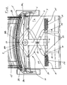
- FIGS. 3 to 7 Further details of a preferred embodiment of a motion-coupled servo device generally designated 29 according to the invention will be explained.
- a total of 29 designated motion-coupled servo device comprises a toggle lever assembly 30, which in the illustrated example, two first toggle elements 31 and two second articulated lifting elements 38, so a total of four toggle lever elements 31, 38 includes.
- this articulated lever assembly 30 is designed scissor-shaped.
- the two first toggle elements 31 intersect at a crossing point 32 at which the toggle elements 31 are rotatably connected to each other.
- the points of articulation of the ends 33 of the articulated lever elements 31 are rotatably mounted on a bearing frame fixed support shaft 34.
- This support shaft 34 is fixedly mounted on the support frame 5 of the office chair, in the vicinity of the cantilevered free end 10 of the support arm 9, which is approximately perpendicular to the horizontal leg 7 and is disposed approximately in the middle thereof.
- the ends 33 of the articulated lever elements 31 is associated with a total of 35 designated spring means which are acted on both sides of the articulation points of the ends 33 on the supporting frame fixed support shaft 34 by spring elements 36 in the form of spiral spring elements of the spring device 35.
- This spring device 35 causes a progressive Federkraftbeetzschung the toggle lever assembly 30.
- the spring means 35 is designed such that it applies by a variable bias corresponding counter forces in coordination with different body weights.
- 36 threaded sleeves can be assigned to the spring elements by means of which by twisting the applied by the spring elements 36 of the spring means 35 and acting on the toggle assembly 30 of the servo device 29 bias can be adjusted in a corresponding manner so that different body weights of a person sitting on the chair can be taken into account.
- the other ends 37 of the first articulated lever elements 31 are also connected to one end 38a of two further articulated lever elements 38 also rotatably and articulated.
- the other ends 38b of the second articulated lever elements 38 are brought together to form a pivot bearing point 39, which is firmly connected to the seat part 14 of the office chair 1.
- the sliding guides 18, by means of which the seat part 14 with respect to the support frame 5 forcibly guided in the synchronous longitudinal displacement with the backrest portion 15 is tilted are also schematically illustrated in the figures, the base frame 2, as it is designed for example in the form of a Primaxgestells and fußgestellmittig the central center axis 4 ( FIGS.
- the toggle assembly 30 is designed symmetrically to a schematically and broken registered line B, which goes through the common pivot bearing point 39 on the seat part 14 and through the intersection point 32 of the first toggle elements 31.
- the support frame fixed support shaft 34 for the pivotal mounting of the ends 33 of the articulated lever elements 31 is arranged substantially perpendicular to the longitudinal displacement direction (arrow A) of the seat part 14.
- FIGS. 4 and 6 the servo 29 is shown in the position in which the backrest part 15 is correspondingly FIG. 6 and FIG. 2 assumes its maximum inclination position and the synchronously hereby coupled seat part 14 occupies its most longitudinally shifted position.
- the spring elements 36 of the spring means 35 at the position in FIG. 4 compressed and compressed, so that hereby a Federkraftbeetzschlagung the servo device 29 in the return direction with a corresponding movement of the backrest part 15 and / or seat part 14 can take place in the direction of rest position, since with the movement of the servo device 29 starting from the FIG. 3 to FIG.
- the spring device 35 forms a force accumulator, which then generates a corresponding resultant application of force to the toggle lever arrangement 30 when the spring elements 36 relax.
- the distance between the intersection point 32 of the first articulated lever elements 31 and the common pivot bearing point 39 on the seat part 14 has been shortened according to the longitudinal displacement of the seat part 14 in longitudinal displacement direction A.
- the spring elements 36 of the spring device 35 by the compression shortened. From the juxtaposition of FIG. 3 and FIG. 4 It can be seen that the seat part 14 covers a relatively large L Lucassverschiebungsweg, while the spring travel of the spring elements 36 of the spring means 35 in relation thereto is relatively small.
- the plurality of articulated lever elements 31, 38 comprehensive, scissor-type articulated lever assembly 30 of the servo device 29 is designed such that in the progressive Federkraftbeetzstoffung by the spring elements 36 of the spring means 35 in each position of the seat part 14 is an approximately constant force transmission to the seat part 14, which is on the relative angular changes of the toggle elements 31, 38 is due to each other.
- a locking device for the movement limitation of the seat part 14 and / or backrest part 15 may be provided at predetermined angles for the backrest part inclination positions.
- a suitable locking device could be assigned to the common pivot bearing point 39 on the seat part 14.
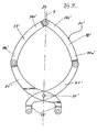
- FIG. 7 is schematically shown in a plan view of an embodiment of a toggle lever assembly 30 ', which comprises first toggle elements 31' and second toggle elements 38 '.
- the toggle elements 31 'and 38' of the toggle assembly 30 ' are at least partially arcuately curved to avoid protruding edges and to give the toggle assembly 30' a shapely appearance.
Applications Claiming Priority (1)
| Application Number | Priority Date | Filing Date | Title |
|---|---|---|---|
| DE102007001194A DE102007001194A1 (de) | 2007-01-05 | 2007-01-05 | Bewegungsgekoppelte Servoeinrichutng für ein Sitzteil, insbesondere eines Stuhls |
Publications (3)
| Publication Number | Publication Date |
|---|---|
| EP1941815A2 true EP1941815A2 (fr) | 2008-07-09 |
| EP1941815A3 EP1941815A3 (fr) | 2009-04-15 |
| EP1941815B1 EP1941815B1 (fr) | 2011-03-23 |
Family
ID=39325643
Family Applications (1)
| Application Number | Title | Priority Date | Filing Date |
|---|---|---|---|
| EP08000107A Expired - Fee Related EP1941815B1 (fr) | 2007-01-05 | 2008-01-04 | Dispositif de direction couplée au mouvement pour une partie de siège, en particulier d'une chaise |
Country Status (5)
| Country | Link |
|---|---|
| US (1) | US7488040B2 (fr) |
| EP (1) | EP1941815B1 (fr) |
| CN (1) | CN101238933B (fr) |
| DE (2) | DE102007001194A1 (fr) |
| HK (1) | HK1120710A1 (fr) |
Cited By (1)
| Publication number | Priority date | Publication date | Assignee | Title |
|---|---|---|---|---|
| ITBS20100020A1 (it) * | 2010-02-05 | 2011-08-06 | Bosio Ermes | Dispositivo di reazione meccanica ad un carico |
Families Citing this family (41)
| Publication number | Priority date | Publication date | Assignee | Title |
|---|---|---|---|---|
| WO2008026264A1 (fr) * | 2006-08-30 | 2008-03-06 | Itoki Corporation | Chaise |
| US20110155069A1 (en) * | 2009-12-29 | 2011-06-30 | Timothy Edmonds | Hammock for a cat or other domestic animal |
| CN201602410U (zh) * | 2010-02-04 | 2010-10-13 | 周金坤 | 一种办公休闲两用椅 |
| KR101533650B1 (ko) * | 2010-04-15 | 2015-07-03 | 주식회사 시디즈 | 의자의 등받이에 작용하는 복원력을 조정하기 위한 조정 메커니즘 및 상기 조정 메커니즘을 구비한 사무용 의자 |
| DE102010033419A1 (de) | 2010-08-04 | 2012-02-09 | Grammer Aktiengesellschaft | Horizontfedereinrichtung für Fahrzeugsitze mit Elastomerfederelement mit progressiver Federkennlinie |
| DE102010052619A1 (de) * | 2010-11-29 | 2012-05-31 | Grammer Aktiengesellschaft | Fahrzeugsitz mit geführten Scherenarmen |
| DE102010053752A1 (de) | 2010-12-08 | 2012-06-14 | Grammer Aktiengesellschaft | Fahrzeugschwingungsvorrichtung für Fahrzeugsitze oder Fahrzeugkabinen |
| JP5724063B2 (ja) * | 2010-12-27 | 2015-05-27 | コクヨ株式会社 | 椅子 |
| DE102011053647B4 (de) | 2011-09-15 | 2022-02-03 | Grammer Aktiengesellschaft | Fahrzeugsitz mit einer Federungsvorrichtung und Kraftfahrzeug |
| DE102012212121A1 (de) * | 2012-07-11 | 2014-01-16 | Eb-Invent Gmbh | Sitzvorrichtung |
| US9415713B2 (en) | 2013-01-24 | 2016-08-16 | Ford Global Technologies, Llc | Flexible seatback system |
| US9409504B2 (en) | 2013-01-24 | 2016-08-09 | Ford Global Technologies, Llc | Flexible seatback system |
| US9016783B2 (en) * | 2013-01-24 | 2015-04-28 | Ford Global Technologies, Llc | Thin seat flex rest composite cushion extension |
| US9399418B2 (en) | 2013-01-24 | 2016-07-26 | Ford Global Technologies, Llc | Independent cushion extension and thigh support |
| AT514846A1 (de) | 2013-09-23 | 2015-04-15 | Camarg Og | Sitzmöbel |
| US9315131B2 (en) | 2014-01-23 | 2016-04-19 | Ford Global Technologies, Llc | Suspension seat back and cushion system having an inner suspension panel |
| US9421894B2 (en) | 2014-04-02 | 2016-08-23 | Ford Global Technologies, Llc | Vehicle seating assembly with manual independent thigh supports |
| US9789790B2 (en) | 2014-10-03 | 2017-10-17 | Ford Global Technologies, Llc | Tuned flexible support member and flexible suspension features for comfort carriers |
| US10046682B2 (en) | 2015-08-03 | 2018-08-14 | Ford Global Technologies, Llc | Back cushion module for a vehicle seating assembly |
| DE102015113176B4 (de) | 2015-08-10 | 2021-12-30 | Grammer Aktiengesellschaft | Horizontalschwingungsvorrichtung für einen Fahrzeugsitz |
| US10286818B2 (en) | 2016-03-16 | 2019-05-14 | Ford Global Technologies, Llc | Dual suspension seating assembly |
| US9849817B2 (en) | 2016-03-16 | 2017-12-26 | Ford Global Technologies, Llc | Composite seat structure |
| US9994135B2 (en) | 2016-03-30 | 2018-06-12 | Ford Global Technologies, Llc | Independent cushion thigh support |
| US10220737B2 (en) | 2016-04-01 | 2019-03-05 | Ford Global Technologies, Llc | Kinematic back panel |
| US9889773B2 (en) | 2016-04-04 | 2018-02-13 | Ford Global Technologies, Llc | Anthropomorphic upper seatback |
| US9802512B1 (en) | 2016-04-12 | 2017-10-31 | Ford Global Technologies, Llc | Torsion spring bushing |
| US9845029B1 (en) | 2016-06-06 | 2017-12-19 | Ford Global Technologies, Llc | Passive conformal seat with hybrid air/liquid cells |
| US9834166B1 (en) | 2016-06-07 | 2017-12-05 | Ford Global Technologies, Llc | Side airbag energy management system |
| US9849856B1 (en) | 2016-06-07 | 2017-12-26 | Ford Global Technologies, Llc | Side airbag energy management system |
| US10166895B2 (en) | 2016-06-09 | 2019-01-01 | Ford Global Technologies, Llc | Seatback comfort carrier |
| US10377279B2 (en) | 2016-06-09 | 2019-08-13 | Ford Global Technologies, Llc | Integrated decking arm support feature |
| US10166894B2 (en) | 2016-06-09 | 2019-01-01 | Ford Global Technologies, Llc | Seatback comfort carrier |
| US10286824B2 (en) | 2016-08-24 | 2019-05-14 | Ford Global Technologies, Llc | Spreader plate load distribution |
| US10279714B2 (en) | 2016-08-26 | 2019-05-07 | Ford Global Technologies, Llc | Seating assembly with climate control features |
| US10239431B2 (en) | 2016-09-02 | 2019-03-26 | Ford Global Technologies, Llc | Cross-tube attachment hook features for modular assembly and support |
| US10391910B2 (en) | 2016-09-02 | 2019-08-27 | Ford Global Technologies, Llc | Modular assembly cross-tube attachment tab designs and functions |
| US9914378B1 (en) | 2016-12-16 | 2018-03-13 | Ford Global Technologies, Llc | Decorative and functional upper seatback closeout assembly |
| US10596936B2 (en) | 2017-05-04 | 2020-03-24 | Ford Global Technologies, Llc | Self-retaining elastic strap for vent blower attachment to a back carrier |
| CN109419196B (zh) * | 2017-08-30 | 2024-01-23 | 永艺家具股份有限公司 | 用于办公椅的背座同步联动装置 |
| US10588416B2 (en) * | 2018-06-28 | 2020-03-17 | Sue Vanmaastricht | Adjustable chair |
| CH715343A1 (de) | 2018-09-18 | 2020-03-31 | Krob Andreas | Drehstuhl. |
Family Cites Families (16)
| Publication number | Priority date | Publication date | Assignee | Title |
|---|---|---|---|---|
| US426602A (en) * | 1890-04-29 | Rest for rocking-chairs | ||
| US953872A (en) * | 1908-10-26 | 1910-04-05 | Edward Vrba | Chair. |
| US3554599A (en) * | 1968-04-27 | 1971-01-12 | Sybron Corp | Longitudinally adjustable back-rest for dental chair and the like |
| GB1375094A (fr) * | 1972-02-02 | 1974-11-27 | ||
| DE3632131C2 (de) * | 1986-06-04 | 2001-12-13 | Hartmut S Engel | Funktions-Sitzmöbel |
| DE3631872C1 (de) * | 1986-09-19 | 1987-10-01 | Daimler Benz Ag | Fahrzeugsitz |
| US4840426A (en) * | 1987-09-30 | 1989-06-20 | Davis Furniture Industries, Inc. | Office chair |
| DE4227329A1 (de) * | 1992-08-18 | 1994-02-24 | Dauphin Friedrich W Gmbh | Stuhl mit Sitztiefenverstellung |
| BR9502131A (pt) * | 1995-05-23 | 1997-08-26 | Lafer S A Ind E Comercio | Poltrona |
| AU8754598A (en) * | 1998-08-13 | 2000-03-06 | Ab Volvo | Adjustable vehicle seat |
| DE29918405U1 (de) * | 1999-10-19 | 1999-12-16 | Interstuhl Bueromoebel Gmbh | Stuhl |
| DE10115501C2 (de) * | 2001-03-29 | 2003-03-27 | Struppler Associates Design Gm | Stuhl, insbesondere Bürostuhl |
| DE10150181A1 (de) * | 2001-10-12 | 2002-04-25 | Hans Rueckstaedter | Kopplung der Bewegung von Rückenlehne und Sitz |
| DE10314709A1 (de) * | 2002-04-07 | 2003-11-20 | Erker Christian | Mechanismus zur Umlenkung von Stützflächen |
| ITMI20022194A1 (it) * | 2002-10-16 | 2004-04-17 | Icf Spa | Sedia avente sedile e schienale mobili. |
| DE10306851A1 (de) | 2003-02-18 | 2004-08-26 | Dózsa-Farkas, Andras | Stuhl, insbesondere Büro- oder Arbeitsstuhl |
-
2007
- 2007-01-05 DE DE102007001194A patent/DE102007001194A1/de not_active Withdrawn
-
2008
- 2008-01-04 EP EP08000107A patent/EP1941815B1/fr not_active Expired - Fee Related
- 2008-01-04 DE DE502008002922T patent/DE502008002922D1/de active Active
- 2008-01-04 US US11/969,490 patent/US7488040B2/en not_active Expired - Fee Related
- 2008-01-07 CN CN2008100024049A patent/CN101238933B/zh not_active Expired - Fee Related
- 2008-11-11 HK HK08112366.3A patent/HK1120710A1/xx not_active IP Right Cessation
Non-Patent Citations (1)
| Title |
|---|
| None |
Cited By (1)
| Publication number | Priority date | Publication date | Assignee | Title |
|---|---|---|---|---|
| ITBS20100020A1 (it) * | 2010-02-05 | 2011-08-06 | Bosio Ermes | Dispositivo di reazione meccanica ad un carico |
Also Published As
| Publication number | Publication date |
|---|---|
| HK1120710A1 (en) | 2009-04-09 |
| EP1941815B1 (fr) | 2011-03-23 |
| CN101238933B (zh) | 2010-06-02 |
| EP1941815A3 (fr) | 2009-04-15 |
| DE102007001194A1 (de) | 2008-07-10 |
| US20080164746A1 (en) | 2008-07-10 |
| DE502008002922D1 (de) | 2011-05-05 |
| CN101238933A (zh) | 2008-08-13 |
| US7488040B2 (en) | 2009-02-10 |
Similar Documents
| Publication | Publication Date | Title |
|---|---|---|
| EP1941815B1 (fr) | Dispositif de direction couplée au mouvement pour une partie de siège, en particulier d'une chaise | |
| EP1318737B1 (fr) | Systeme d'entrainement pour meuble, se presentant sous la forme d'un double dispositif d'entrainement | |
| EP1492702B1 (fr) | Appui-tete pour siege | |
| DE102008026715B4 (de) | Aktives Kopfstützensystem mit Betätigungssystem für einen Fahrzeugsitz | |
| AT402602B (de) | Stuhl stuhl | |
| DE19848603B4 (de) | Verstellbare Sitzaufhängung | |
| EP2187781B1 (fr) | Fauteuil, notamment fauteuil de dentiste, présentant une assise avec des appuie-jambes inclinables | |
| DE102015101546B4 (de) | Synchronmechanik | |
| EP1230876A1 (fr) | Meuble d'assise | |
| WO2015040008A1 (fr) | Siège | |
| EP1850699B1 (fr) | Meuble, en particulier meuble d'assise | |
| DE3844102A1 (de) | Sitz fuer einen buerostuhl od. dgl. | |
| WO2004073457A1 (fr) | Chaise, en particulier chaise de bureau ou de travail | |
| DE19913503A1 (de) | Fahrzeugsitz mit Sitztiefenverstellung | |
| EP1874160B1 (fr) | Siege, notamment chaise de bureau | |
| DE60221793T2 (de) | Stühle | |
| EP1258211B1 (fr) | Mécanisme synchronisé pour un mouvement correlé entre une siège et un dossier des chaises de bureau | |
| DE602005004111T2 (de) | Trägerstruktur für einen Sitz mit einer Tischfunktion und entsprechende Sitzfederungsanordnung | |
| WO2016124317A1 (fr) | Mecanisme synchrone | |
| DE202005004932U1 (de) | Bewegungsbeschlag | |
| EP3626521B1 (fr) | Dispositif de couverture pour sièges de véhicule | |
| EP2477523B1 (fr) | Mécanisme de bascule pour une chaise de bureau | |
| EP3528664B1 (fr) | Dispositif de mécanisme synchrone et chaise en étant équipée | |
| WO2010028412A1 (fr) | Dispositif pour régler la résistance au pivotement d'un dossier | |
| WO2014183851A1 (fr) | Mécanique synchrone |
Legal Events
| Date | Code | Title | Description |
|---|---|---|---|
| PUAI | Public reference made under article 153(3) epc to a published international application that has entered the european phase |
Free format text: ORIGINAL CODE: 0009012 |
|
| AK | Designated contracting states |
Kind code of ref document: A2 Designated state(s): AT BE BG CH CY CZ DE DK EE ES FI FR GB GR HR HU IE IS IT LI LT LU LV MC MT NL NO PL PT RO SE SI SK TR |
|
| AX | Request for extension of the european patent |
Extension state: AL BA MK RS |
|
| PUAL | Search report despatched |
Free format text: ORIGINAL CODE: 0009013 |
|
| AK | Designated contracting states |
Kind code of ref document: A3 Designated state(s): AT BE BG CH CY CZ DE DK EE ES FI FR GB GR HR HU IE IS IT LI LT LU LV MC MT NL NO PL PT RO SE SI SK TR |
|
| AX | Request for extension of the european patent |
Extension state: AL BA MK RS |
|
| 17P | Request for examination filed |
Effective date: 20091015 |
|
| AKX | Designation fees paid |
Designated state(s): DE ES GB IT |
|
| 17Q | First examination report despatched |
Effective date: 20091218 |
|
| GRAP | Despatch of communication of intention to grant a patent |
Free format text: ORIGINAL CODE: EPIDOSNIGR1 |
|
| GRAS | Grant fee paid |
Free format text: ORIGINAL CODE: EPIDOSNIGR3 |
|
| GRAA | (expected) grant |
Free format text: ORIGINAL CODE: 0009210 |
|
| AK | Designated contracting states |
Kind code of ref document: B1 Designated state(s): DE ES GB IT |
|
| REG | Reference to a national code |
Ref country code: GB Ref legal event code: FG4D Free format text: NOT ENGLISH |
|
| REF | Corresponds to: |
Ref document number: 502008002922 Country of ref document: DE Date of ref document: 20110505 Kind code of ref document: P |
|
| REG | Reference to a national code |
Ref country code: DE Ref legal event code: R096 Ref document number: 502008002922 Country of ref document: DE Effective date: 20110505 |
|
| PG25 | Lapsed in a contracting state [announced via postgrant information from national office to epo] |
Ref country code: ES Free format text: LAPSE BECAUSE OF FAILURE TO SUBMIT A TRANSLATION OF THE DESCRIPTION OR TO PAY THE FEE WITHIN THE PRESCRIBED TIME-LIMIT Effective date: 20110704 |
|
| PLBE | No opposition filed within time limit |
Free format text: ORIGINAL CODE: 0009261 |
|
| STAA | Information on the status of an ep patent application or granted ep patent |
Free format text: STATUS: NO OPPOSITION FILED WITHIN TIME LIMIT |
|
| 26N | No opposition filed |
Effective date: 20111227 |
|
| REG | Reference to a national code |
Ref country code: DE Ref legal event code: R097 Ref document number: 502008002922 Country of ref document: DE Effective date: 20111227 |
|
| PG25 | Lapsed in a contracting state [announced via postgrant information from national office to epo] |
Ref country code: IT Free format text: LAPSE BECAUSE OF FAILURE TO SUBMIT A TRANSLATION OF THE DESCRIPTION OR TO PAY THE FEE WITHIN THE PRESCRIBED TIME-LIMIT Effective date: 20110323 |
|
| GBPC | Gb: european patent ceased through non-payment of renewal fee |
Effective date: 20120104 |
|
| PG25 | Lapsed in a contracting state [announced via postgrant information from national office to epo] |
Ref country code: GB Free format text: LAPSE BECAUSE OF NON-PAYMENT OF DUE FEES Effective date: 20120104 Ref country code: DE Free format text: LAPSE BECAUSE OF NON-PAYMENT OF DUE FEES Effective date: 20120801 |
|
| REG | Reference to a national code |
Ref country code: DE Ref legal event code: R119 Ref document number: 502008002922 Country of ref document: DE Effective date: 20120801 |