EP2477523B1 - Mécanisme de bascule pour une chaise de bureau - Google Patents
Mécanisme de bascule pour une chaise de bureau Download PDFInfo
- Publication number
- EP2477523B1 EP2477523B1 EP10765368.5A EP10765368A EP2477523B1 EP 2477523 B1 EP2477523 B1 EP 2477523B1 EP 10765368 A EP10765368 A EP 10765368A EP 2477523 B1 EP2477523 B1 EP 2477523B1
- Authority
- EP
- European Patent Office
- Prior art keywords
- seat
- support
- seat support
- longitudinal direction
- base support
- Prior art date
- Legal status (The legal status is an assumption and is not a legal conclusion. Google has not performed a legal analysis and makes no representation as to the accuracy of the status listed.)
- Active
Links
Images


Classifications
-
- A—HUMAN NECESSITIES
- A47—FURNITURE; DOMESTIC ARTICLES OR APPLIANCES; COFFEE MILLS; SPICE MILLS; SUCTION CLEANERS IN GENERAL
- A47C—CHAIRS; SOFAS; BEDS
- A47C3/00—Chairs characterised by structural features; Chairs or stools with rotatable or vertically-adjustable seats
- A47C3/02—Rocking chairs
- A47C3/025—Rocking chairs with seat, or seat and back-rest unit elastically or pivotally mounted in a rigid base frame
- A47C3/026—Rocking chairs with seat, or seat and back-rest unit elastically or pivotally mounted in a rigid base frame with central column, e.g. rocking office chairs; Tilting chairs
-
- A—HUMAN NECESSITIES
- A47—FURNITURE; DOMESTIC ARTICLES OR APPLIANCES; COFFEE MILLS; SPICE MILLS; SUCTION CLEANERS IN GENERAL
- A47C—CHAIRS; SOFAS; BEDS
- A47C7/00—Parts, details, or accessories of chairs or stools
- A47C7/36—Support for the head or the back
- A47C7/40—Support for the head or the back for the back
- A47C7/44—Support for the head or the back for the back with elastically-mounted back-rest or backrest-seat unit in the base frame
- A47C7/443—Support for the head or the back for the back with elastically-mounted back-rest or backrest-seat unit in the base frame with coil springs
Definitions
- the invention relates to a Wippmechanik for an office chair with a placeable on a chair column base support, with a seat support and with a rigidly connected to the seat support backrest support.
- So-called synchronous mechanisms are known from the prior art. These are assemblies in the seat base of an office chair, which allow a correlated seat-backrest movement. Seat support and backrest support are coupled so articulated that a pivoting movement of the backrest to the rear, as can be caused for example by leaning of the chair user to the backrest, induces a lowering movement of the rear edge of the seat down. This brings a considerable comfort advantage and is desirable for orthopedic reasons.
- a disadvantage of these synchronous mechanisms is their relatively complicated mechanical structure. As a result, synchronous mechanisms are also relatively expensive to manufacture.
- An object of the present invention is to provide a mechanism for an office chair, which provides a comfort advantage with a comparatively small design effort, which is comparable to that of a synchronous mechanism.
- a core idea of the invention is to prevent the tilting effect which is otherwise customary in the case of rocker mechanisms, in that the rotational movement of the seat carrier backrest carrier combination towards the rear, downwards, results in a linear movement of the seat carrier. is superimposed in the longitudinal direction to the rear.
- the resulting overall movement of the seat post backrest support combination results in the user making a movement approximating the movement that a user would make in using a synchronous mechanism.
- a seating comfort is achieved in a structurally simple and therefore also very inexpensive way, which otherwise can only be achieved with a much more expensive synchronous mechanism.
- the desired rotation-translation movement can be achieved in that the connection of seat support and base support is formed at two pivot points by first and second link, which are pivotally connected to seat support or base support.
- the arrangement of the articulation points of the handlebars on seat support and base support and the distance of the articulation points of the links with each other or the distance of the articulation points of the links to each other is preferably chosen such that a particularly comfortable and ergonomic movement of the seat support backrest support combination takes place.
- the size of these differences in length has a direct influence on the angle of rotation of the seat carrier backrest support combination with a pivoting movement of the backrest to the rear.
- the front (first) arm is designed such that it abuts in the non-pivoted starting position of the base body of the base support. This avoids unintentional pivoting of the seat carrier forward beyond the initial position.
- the front pivot point is realized by a linear bearing in a structurally also particularly simple embodiment of the invention.
- the seen in the seat longitudinal direction front pivot point at which the seat support is pivotally connected to the base support realized by a rotary / sliding joint in which the Seat support to form a pivotal connection is directly and directly hingedly connected to the base support, while - as in the embodiment described above - a number of the rotary / sliding joint in the seat longitudinal direction spaced handlebars are provided, the one hand articulated to form pivotal connections Seat support and on the other hand hinged to the base support are connected.
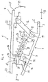
- the example is based on the Fig. 1 and 2 described (not part of the invention).
- the rocking mechanism 1 has a base support 2, which is set by means of a cone seat 3 on the upper end of a chair column (not shown).
- the Wippmechanik 1 comprises a substantially frame-shaped seat support 4, which is rigidly connected to a arranged at the rear end 5 of the seat support 4 backrest support (not shown).
- the seat support 4 is provided for receiving or mounting a preferably padded seat (not shown). On the backrest support a backrest is attached.
- the entire rocking mechanism 1 is mirror-symmetrical with respect to its central longitudinal plane, as far as the actual kinematics is concerned. In that regard, in the following description is always based on both sides in pairs existing construction elements of the rocking mechanism 1.
- FIG. 1 the starting position is shown, in which the seat support 4 assumes a substantially horizontal position.
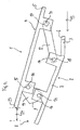
- Fig. 2 shows the rocking mechanism 1 in a rearwardly pivoted position.
- the cone seat 3 is provided for the upper end of the chair column.
- the basic body 7 of the base support 2, which initially runs horizontally in the area of the cone seat 3, is angled downstream of the cone seat 3 in such a way that the distance from the base support 2 to the seat support 4 in the front area 8 of the mechanism 1 is less than in the rear area 5, 6.
- first links 11 and two second links 12 are provided, which are arranged on both sides of the seat support 4 and base support 2 and seat support 4 and base support 2 interconnect.
- first links 11 and two second links 12 are spaced from each other in the seat longitudinal direction 13 and pivotally connected to the seat support 4 and on the other hand articulated to the base support 2 to form pivotal connections 14. They thus form two in the seat longitudinal direction 13 spaced pivot points 15, 16 and 17, 18, in which the seat support 4 is connected to the base support 2.
- the first link 11 with its abutment surface 9 abuts on the main body 7 of the base support 2 and thus prevents unintentional pivoting of the seat support 4 forward.
- the distance of the articulation points 17, 18 of the second link 12 to each other is greater than the distance of the articulation points 15, 16 of the first link 11 to each other.
- the pivot points 17 of the second arm 12 on the seat support 4 are in the seat longitudinal direction 13 always behind the pivot points 18 of the second arm 12 on the base support. 2
- the described arrangement and design of the links 11, 12 causes pivotal movement of the seat post back-up combination to induce the desired rotational-translational motion, in which the pivotal movement 21 of the seat post 4 extends rearwardly from a linear motion 22 of the seat post 4 is superimposed in the seat longitudinal direction 13 to the rear, cf. Fig. 1 ,
- the front end 23 of the seat support 4 is in the pivoting position ( Fig. 2 ) relative to the starting position ( Fig. 1 ) only slightly raised, but shifted by a path 24 to the rear.
- a number of spring elements are provided, which may be, for example, tension or compression springs.
- a single central compression spring 25 is provided, which communicates with its one Spring end 26 is supported on a transverse axis 27, which connects the articulation points 15 of the first link 11.
- a guide rod 28 is used, which prevents kink protection that the compression spring 25 kinks during compression.
- the guide rod 28 forms at its transverse axis 27 opposite end of a spring plate 29, which serves as a stop for the other spring end 31.
- the vertical position of the spring plate 29 is adjustable to change the bias of the compression spring 25.
- the rounded outer side of the spring plate 29 is in a provided with a depression in the manner of a ball socket traversing element 32 a.
- the position of the displacement element 32 is variable relative to the base support in the vertical direction 33.
- adjusting mechanism for example, serves via a handwheel adjustable gear transmission (not shown).
- compression spring 25 and displacement element 32 are in Fig. 2 not pictured.
- the compression spring 25 When pivoting the seat carrier backrest support combination, the compression spring 25 is compressed. In other words, the user must pivot the backrest against the spring force. By adjusting the Verfahrelements 32 upwards, the compression spring 25 is compressed and thereby increases the bias of the compression spring 25. The user thus needs to exert more force to pivot the seat back support back combination down rear.
- This embodiment corresponds essentially to the example described above, with the difference that instead of the front first link for articulated connection of the seat support 4 to the base support 2, a linear bearing is used, which is designed as a rotary / sliding joint. Such a joint allows both the desired rotational, as well as the desired translational movement of the seat support 4 relative to the base support 2. It thus replaces the first arm used in the first embodiment, both on the seat support 4, and on the base support 2 11th
- the seat support 4 is connected at its front end portion 23 with the base support 2 directly, ie without the use of a handlebar, via a number of rotary / sliding joints 34.
- Each of these joints consists of a connected to the seat support 4 or formed as part of the seat support 4 sliding member 35 which rests in a sliding guide, which is formed by two spaced-apart sliding blocks 36, 37, which are fixedly connected to the base support 2.
- the sliding jaws 36, 37 are parts of receiving arms, which extend for this purpose from the front region of the base support base 7 out upward in the direction of the seat support 4.
- Both sliding jaws 36, 37 have spherical guide surfaces, which allow that the sliding member 35 and thus also connected to the slide member 35 in the seat support 4 and the pivoting movement can be traced back down.
- the trained in the manner of a rail slide member 35 moves in other words with its top 38 and its bottom 39 on the guide surfaces of the upper and lower slide shoe 36, 37 along, the slider 35 in any pivot state between the upper and lower slide jaw 36, 37 safe is guided.
- This shape of the rotary / sliding joint can be replaced by other types of rotary / sliding joints.
Claims (1)
- Mécanisme de bascule (1) pour une chaise de bureau :- avec un support de base (2) pouvant être placé sur une colonne de chaise ;- avec un support de siège (4) ;- avec un support de dossier relié de façon rigide au support de siège (4) ;
le support de siège (4) étant relié de telle sorte au support de base (2) au niveau de deux points de pivotement (16, 18) espacés l'un par rapport à l'autre dans la direction longitudinale de siège (13) qu'un mouvement de basculement du support de dossier vers l'arrière et le bas induit un mouvement de rotation (21) du support de siège (4) vers l'arrière et le bas, ledit mouvement étant rehaussé vers l'arrière par un mouvement de translation (22) du support de siège (4) dans la direction longitudinale de siège (13) ;
le point de pivotement (16) avant, vu dans la direction longitudinale de siège (13), étant concrétisé par une articulation de pivotement-poussée dans laquelle le support de siège (4) est relié par articulation directe au support de base (2) par formation d'une liaison basculante (14) ; et- avec un certain nombre de bielles (12) placées à une certaine distance de l'articulation de pivotement-poussée, dans la direction longitudinale de siège (13) et reliées d'une part de façon articulée au support de siège (4) et d'autre part de façon articulée au support de base (2) par formation de liaisons basculantes (14) ;
caractérisé en ce que les points de commande (17) des bielles (12) positionnées au niveau du support de siège (4), dans la direction longitudinale de siège (13), se situent toujours derrière les points de commande (18) des bielles (12) positionnées au niveau du support de base (2).
Applications Claiming Priority (2)
| Application Number | Priority Date | Filing Date | Title |
|---|---|---|---|
| DE102009041296 | 2009-09-15 | ||
| PCT/EP2010/005652 WO2011032689A1 (fr) | 2009-09-15 | 2010-09-15 | Mécanisme de bascule pour une chaise de bureau |
Publications (2)
| Publication Number | Publication Date |
|---|---|
| EP2477523A1 EP2477523A1 (fr) | 2012-07-25 |
| EP2477523B1 true EP2477523B1 (fr) | 2013-06-05 |
Family
ID=43244859
Family Applications (1)
| Application Number | Title | Priority Date | Filing Date |
|---|---|---|---|
| EP10765368.5A Active EP2477523B1 (fr) | 2009-09-15 | 2010-09-15 | Mécanisme de bascule pour une chaise de bureau |
Country Status (3)
| Country | Link |
|---|---|
| EP (1) | EP2477523B1 (fr) |
| DE (1) | DE102010045456A1 (fr) |
| WO (1) | WO2011032689A1 (fr) |
Cited By (1)
| Publication number | Priority date | Publication date | Assignee | Title |
|---|---|---|---|---|
| US11350750B2 (en) | 2018-04-17 | 2022-06-07 | L&P Property Management Company | Tilt mechanism for a chair and chair |
Families Citing this family (1)
| Publication number | Priority date | Publication date | Assignee | Title |
|---|---|---|---|---|
| US10383448B1 (en) | 2018-03-28 | 2019-08-20 | Haworth, Inc. | Forward tilt assembly for chair seat |
Family Cites Families (4)
| Publication number | Priority date | Publication date | Assignee | Title |
|---|---|---|---|---|
| FR1045316A (fr) * | 1951-11-20 | 1953-11-25 | Suspension pour sièges | |
| DE3743013A1 (de) * | 1987-12-18 | 1989-06-29 | Froescher August Gmbh Co Kg | Sitz-rueckenlehnen-einheit fuer arbeitsstuhl |
| JPH0613595U (ja) * | 1992-03-27 | 1994-02-22 | 株式会社コーソー | パチンコ店等店用の自動復帰椅子 |
| JP4286430B2 (ja) * | 2000-05-22 | 2009-07-01 | タカノ株式会社 | 椅子のロッキング装置 |
-
2010
- 2010-09-15 EP EP10765368.5A patent/EP2477523B1/fr active Active
- 2010-09-15 DE DE102010045456A patent/DE102010045456A1/de not_active Withdrawn
- 2010-09-15 WO PCT/EP2010/005652 patent/WO2011032689A1/fr active Application Filing
Cited By (1)
| Publication number | Priority date | Publication date | Assignee | Title |
|---|---|---|---|---|
| US11350750B2 (en) | 2018-04-17 | 2022-06-07 | L&P Property Management Company | Tilt mechanism for a chair and chair |
Also Published As
| Publication number | Publication date |
|---|---|
| EP2477523A1 (fr) | 2012-07-25 |
| DE102010045456A1 (de) | 2011-03-24 |
| WO2011032689A1 (fr) | 2011-03-24 |
Similar Documents
| Publication | Publication Date | Title |
|---|---|---|
| EP1946676B1 (fr) | Chaise | |
| DE3741472C2 (fr) | ||
| EP1396213B1 (fr) | Mécanisme synchronisé pour chaises de bureau | |
| WO2001091614A1 (fr) | Chaise | |
| DE102015101546B4 (de) | Synchronmechanik | |
| WO2011141107A1 (fr) | Mécanisme de réglage d'une force de rappel agissant sur le dossier d'un siège et siège de bureau doté d'un mécanisme de ce type | |
| DE102005029906B3 (de) | Synchronmechanik | |
| EP3120732B1 (fr) | Mecanisme de siege de bureau | |
| DE102006023981A1 (de) | Stuhl | |
| EP3741258A1 (fr) | Chaise pourvue de mécanisme d'inclinaison de l'assise | |
| DE102015101545A1 (de) | Synchronmechanik | |
| EP2561777B1 (fr) | Mécanisme synchrone pour une chaise | |
| EP3345507B1 (fr) | Mécanisme pour une chaise | |
| EP2670279B1 (fr) | Mécanique synchrone | |
| EP2477523B1 (fr) | Mécanisme de bascule pour une chaise de bureau | |
| DE202011000805U1 (de) | Stuhl mit kipp- und torsionsbeweglicher Sitzfläche | |
| EP1974633A2 (fr) | Meubles destinés à s'asseoir | |
| EP2994017B1 (fr) | Mécanique synchrone | |
| WO2001091613A1 (fr) | Chaise | |
| DE102020124975A1 (de) | Mechanik für einen Stuhl | |
| EP3100642B1 (fr) | Mecanisme pour une chaise comprenant un mecanisme synchrone ; procede de reglage de poids pour un meilleur confort d'assise dynamique de l'utilisateur au moyen d'un mecanisme pour une chaise comprenant un mecanisme synchrone | |
| EP3253255B1 (fr) | Mecanisme synchrone | |
| WO2014177445A1 (fr) | Chaise comprenant un mécanisme de siège | |
| WO2018073222A1 (fr) | Mécanisme synchronisé pour chaise et chaise comprenant un tel mécanisme | |
| DE19700617C5 (de) | Sessel |
Legal Events
| Date | Code | Title | Description |
|---|---|---|---|
| PUAI | Public reference made under article 153(3) epc to a published international application that has entered the european phase |
Free format text: ORIGINAL CODE: 0009012 |
|
| 17P | Request for examination filed |
Effective date: 20120322 |
|
| AK | Designated contracting states |
Kind code of ref document: A1 Designated state(s): AL AT BE BG CH CY CZ DE DK EE ES FI FR GB GR HR HU IE IS IT LI LT LU LV MC MK MT NL NO PL PT RO SE SI SK SM TR |
|
| DAX | Request for extension of the european patent (deleted) | ||
| GRAP | Despatch of communication of intention to grant a patent |
Free format text: ORIGINAL CODE: EPIDOSNIGR1 |
|
| GRAS | Grant fee paid |
Free format text: ORIGINAL CODE: EPIDOSNIGR3 |
|
| GRAA | (expected) grant |
Free format text: ORIGINAL CODE: 0009210 |
|
| AK | Designated contracting states |
Kind code of ref document: B1 Designated state(s): AL AT BE BG CH CY CZ DE DK EE ES FI FR GB GR HR HU IE IS IT LI LT LU LV MC MK MT NL NO PL PT RO SE SI SK SM TR |
|
| REG | Reference to a national code |
Ref country code: GB Ref legal event code: FG4D Free format text: NOT ENGLISH |
|
| REG | Reference to a national code |
Ref country code: CH Ref legal event code: EP |
|
| REG | Reference to a national code |
Ref country code: AT Ref legal event code: REF Ref document number: 615126 Country of ref document: AT Kind code of ref document: T Effective date: 20130615 |
|
| REG | Reference to a national code |
Ref country code: IE Ref legal event code: FG4D Free format text: LANGUAGE OF EP DOCUMENT: GERMAN |
|
| REG | Reference to a national code |
Ref country code: DE Ref legal event code: R096 Ref document number: 502010003610 Country of ref document: DE Effective date: 20130801 |
|
| PG25 | Lapsed in a contracting state [announced via postgrant information from national office to epo] |
Ref country code: FI Free format text: LAPSE BECAUSE OF FAILURE TO SUBMIT A TRANSLATION OF THE DESCRIPTION OR TO PAY THE FEE WITHIN THE PRESCRIBED TIME-LIMIT Effective date: 20130605 Ref country code: LT Free format text: LAPSE BECAUSE OF FAILURE TO SUBMIT A TRANSLATION OF THE DESCRIPTION OR TO PAY THE FEE WITHIN THE PRESCRIBED TIME-LIMIT Effective date: 20130605 Ref country code: GR Free format text: LAPSE BECAUSE OF FAILURE TO SUBMIT A TRANSLATION OF THE DESCRIPTION OR TO PAY THE FEE WITHIN THE PRESCRIBED TIME-LIMIT Effective date: 20130906 Ref country code: SI Free format text: LAPSE BECAUSE OF FAILURE TO SUBMIT A TRANSLATION OF THE DESCRIPTION OR TO PAY THE FEE WITHIN THE PRESCRIBED TIME-LIMIT Effective date: 20130605 Ref country code: NO Free format text: LAPSE BECAUSE OF FAILURE TO SUBMIT A TRANSLATION OF THE DESCRIPTION OR TO PAY THE FEE WITHIN THE PRESCRIBED TIME-LIMIT Effective date: 20130905 Ref country code: ES Free format text: LAPSE BECAUSE OF FAILURE TO SUBMIT A TRANSLATION OF THE DESCRIPTION OR TO PAY THE FEE WITHIN THE PRESCRIBED TIME-LIMIT Effective date: 20130916 Ref country code: SE Free format text: LAPSE BECAUSE OF FAILURE TO SUBMIT A TRANSLATION OF THE DESCRIPTION OR TO PAY THE FEE WITHIN THE PRESCRIBED TIME-LIMIT Effective date: 20130605 |
|
| REG | Reference to a national code |
Ref country code: NL Ref legal event code: VDEP Effective date: 20130605 |
|
| REG | Reference to a national code |
Ref country code: LT Ref legal event code: MG4D |
|
| PG25 | Lapsed in a contracting state [announced via postgrant information from national office to epo] |
Ref country code: HR Free format text: LAPSE BECAUSE OF FAILURE TO SUBMIT A TRANSLATION OF THE DESCRIPTION OR TO PAY THE FEE WITHIN THE PRESCRIBED TIME-LIMIT Effective date: 20130605 Ref country code: BG Free format text: LAPSE BECAUSE OF FAILURE TO SUBMIT A TRANSLATION OF THE DESCRIPTION OR TO PAY THE FEE WITHIN THE PRESCRIBED TIME-LIMIT Effective date: 20130905 |
|
| PG25 | Lapsed in a contracting state [announced via postgrant information from national office to epo] |
Ref country code: LV Free format text: LAPSE BECAUSE OF FAILURE TO SUBMIT A TRANSLATION OF THE DESCRIPTION OR TO PAY THE FEE WITHIN THE PRESCRIBED TIME-LIMIT Effective date: 20130605 |
|
| PG25 | Lapsed in a contracting state [announced via postgrant information from national office to epo] |
Ref country code: CZ Free format text: LAPSE BECAUSE OF FAILURE TO SUBMIT A TRANSLATION OF THE DESCRIPTION OR TO PAY THE FEE WITHIN THE PRESCRIBED TIME-LIMIT Effective date: 20130605 Ref country code: EE Free format text: LAPSE BECAUSE OF FAILURE TO SUBMIT A TRANSLATION OF THE DESCRIPTION OR TO PAY THE FEE WITHIN THE PRESCRIBED TIME-LIMIT Effective date: 20130605 Ref country code: SK Free format text: LAPSE BECAUSE OF FAILURE TO SUBMIT A TRANSLATION OF THE DESCRIPTION OR TO PAY THE FEE WITHIN THE PRESCRIBED TIME-LIMIT Effective date: 20130605 Ref country code: IS Free format text: LAPSE BECAUSE OF FAILURE TO SUBMIT A TRANSLATION OF THE DESCRIPTION OR TO PAY THE FEE WITHIN THE PRESCRIBED TIME-LIMIT Effective date: 20131005 Ref country code: PT Free format text: LAPSE BECAUSE OF FAILURE TO SUBMIT A TRANSLATION OF THE DESCRIPTION OR TO PAY THE FEE WITHIN THE PRESCRIBED TIME-LIMIT Effective date: 20131007 |
|
| PG25 | Lapsed in a contracting state [announced via postgrant information from national office to epo] |
Ref country code: NL Free format text: LAPSE BECAUSE OF FAILURE TO SUBMIT A TRANSLATION OF THE DESCRIPTION OR TO PAY THE FEE WITHIN THE PRESCRIBED TIME-LIMIT Effective date: 20130605 Ref country code: RO Free format text: LAPSE BECAUSE OF FAILURE TO SUBMIT A TRANSLATION OF THE DESCRIPTION OR TO PAY THE FEE WITHIN THE PRESCRIBED TIME-LIMIT Effective date: 20130605 Ref country code: PL Free format text: LAPSE BECAUSE OF FAILURE TO SUBMIT A TRANSLATION OF THE DESCRIPTION OR TO PAY THE FEE WITHIN THE PRESCRIBED TIME-LIMIT Effective date: 20130605 |
|
| BERE | Be: lapsed |
Owner name: BOCK 1 G.M.B.H. & CO. KG Effective date: 20130930 |
|
| PLBE | No opposition filed within time limit |
Free format text: ORIGINAL CODE: 0009261 |
|
| STAA | Information on the status of an ep patent application or granted ep patent |
Free format text: STATUS: NO OPPOSITION FILED WITHIN TIME LIMIT |
|
| PG25 | Lapsed in a contracting state [announced via postgrant information from national office to epo] |
Ref country code: DK Free format text: LAPSE BECAUSE OF FAILURE TO SUBMIT A TRANSLATION OF THE DESCRIPTION OR TO PAY THE FEE WITHIN THE PRESCRIBED TIME-LIMIT Effective date: 20130605 Ref country code: MC Free format text: LAPSE BECAUSE OF FAILURE TO SUBMIT A TRANSLATION OF THE DESCRIPTION OR TO PAY THE FEE WITHIN THE PRESCRIBED TIME-LIMIT Effective date: 20130605 |
|
| 26N | No opposition filed |
Effective date: 20140306 |
|
| PG25 | Lapsed in a contracting state [announced via postgrant information from national office to epo] |
Ref country code: IT Free format text: LAPSE BECAUSE OF FAILURE TO SUBMIT A TRANSLATION OF THE DESCRIPTION OR TO PAY THE FEE WITHIN THE PRESCRIBED TIME-LIMIT Effective date: 20130605 |
|
| REG | Reference to a national code |
Ref country code: DE Ref legal event code: R097 Ref document number: 502010003610 Country of ref document: DE Effective date: 20140306 |
|
| REG | Reference to a national code |
Ref country code: FR Ref legal event code: ST Effective date: 20140530 |
|
| REG | Reference to a national code |
Ref country code: IE Ref legal event code: MM4A |
|
| PG25 | Lapsed in a contracting state [announced via postgrant information from national office to epo] |
Ref country code: BE Free format text: LAPSE BECAUSE OF NON-PAYMENT OF DUE FEES Effective date: 20130930 Ref country code: IE Free format text: LAPSE BECAUSE OF NON-PAYMENT OF DUE FEES Effective date: 20130915 |
|
| PG25 | Lapsed in a contracting state [announced via postgrant information from national office to epo] |
Ref country code: FR Free format text: LAPSE BECAUSE OF NON-PAYMENT OF DUE FEES Effective date: 20130930 |
|
| REG | Reference to a national code |
Ref country code: CH Ref legal event code: PL |
|
| GBPC | Gb: european patent ceased through non-payment of renewal fee |
Effective date: 20140915 |
|
| PG25 | Lapsed in a contracting state [announced via postgrant information from national office to epo] |
Ref country code: SM Free format text: LAPSE BECAUSE OF FAILURE TO SUBMIT A TRANSLATION OF THE DESCRIPTION OR TO PAY THE FEE WITHIN THE PRESCRIBED TIME-LIMIT Effective date: 20130605 |
|
| PG25 | Lapsed in a contracting state [announced via postgrant information from national office to epo] |
Ref country code: CY Free format text: LAPSE BECAUSE OF FAILURE TO SUBMIT A TRANSLATION OF THE DESCRIPTION OR TO PAY THE FEE WITHIN THE PRESCRIBED TIME-LIMIT Effective date: 20130605 Ref country code: TR Free format text: LAPSE BECAUSE OF FAILURE TO SUBMIT A TRANSLATION OF THE DESCRIPTION OR TO PAY THE FEE WITHIN THE PRESCRIBED TIME-LIMIT Effective date: 20130605 Ref country code: MT Free format text: LAPSE BECAUSE OF FAILURE TO SUBMIT A TRANSLATION OF THE DESCRIPTION OR TO PAY THE FEE WITHIN THE PRESCRIBED TIME-LIMIT Effective date: 20130605 |
|
| PG25 | Lapsed in a contracting state [announced via postgrant information from national office to epo] |
Ref country code: LI Free format text: LAPSE BECAUSE OF NON-PAYMENT OF DUE FEES Effective date: 20140930 Ref country code: MK Free format text: LAPSE BECAUSE OF FAILURE TO SUBMIT A TRANSLATION OF THE DESCRIPTION OR TO PAY THE FEE WITHIN THE PRESCRIBED TIME-LIMIT Effective date: 20130605 Ref country code: GB Free format text: LAPSE BECAUSE OF NON-PAYMENT OF DUE FEES Effective date: 20140915 Ref country code: HU Free format text: LAPSE BECAUSE OF FAILURE TO SUBMIT A TRANSLATION OF THE DESCRIPTION OR TO PAY THE FEE WITHIN THE PRESCRIBED TIME-LIMIT; INVALID AB INITIO Effective date: 20100915 Ref country code: LU Free format text: LAPSE BECAUSE OF NON-PAYMENT OF DUE FEES Effective date: 20130915 Ref country code: CH Free format text: LAPSE BECAUSE OF NON-PAYMENT OF DUE FEES Effective date: 20140930 |
|
| REG | Reference to a national code |
Ref country code: AT Ref legal event code: MM01 Ref document number: 615126 Country of ref document: AT Kind code of ref document: T Effective date: 20150915 |
|
| PG25 | Lapsed in a contracting state [announced via postgrant information from national office to epo] |
Ref country code: AT Free format text: LAPSE BECAUSE OF NON-PAYMENT OF DUE FEES Effective date: 20150915 |
|
| PG25 | Lapsed in a contracting state [announced via postgrant information from national office to epo] |
Ref country code: AL Free format text: LAPSE BECAUSE OF FAILURE TO SUBMIT A TRANSLATION OF THE DESCRIPTION OR TO PAY THE FEE WITHIN THE PRESCRIBED TIME-LIMIT Effective date: 20130605 |
|
| PGFP | Annual fee paid to national office [announced via postgrant information from national office to epo] |
Ref country code: DE Payment date: 20220824 Year of fee payment: 13 |