EP1932707A1 - Kühlvorrichtung für maschinen im fahrzeug - Google Patents
Kühlvorrichtung für maschinen im fahrzeug Download PDFInfo
- Publication number
- EP1932707A1 EP1932707A1 EP06810691A EP06810691A EP1932707A1 EP 1932707 A1 EP1932707 A1 EP 1932707A1 EP 06810691 A EP06810691 A EP 06810691A EP 06810691 A EP06810691 A EP 06810691A EP 1932707 A1 EP1932707 A1 EP 1932707A1
- Authority
- EP
- European Patent Office
- Prior art keywords
- battery
- medium
- cooling
- converter
- supply passage
- Prior art date
- Legal status (The legal status is an assumption and is not a legal conclusion. Google has not performed a legal analysis and makes no representation as to the accuracy of the status listed.)
- Granted
Links
Images


Classifications
-
- B—PERFORMING OPERATIONS; TRANSPORTING
- B60—VEHICLES IN GENERAL
- B60K—ARRANGEMENT OR MOUNTING OF PROPULSION UNITS OR OF TRANSMISSIONS IN VEHICLES; ARRANGEMENT OR MOUNTING OF PLURAL DIVERSE PRIME-MOVERS IN VEHICLES; AUXILIARY DRIVES FOR VEHICLES; INSTRUMENTATION OR DASHBOARDS FOR VEHICLES; ARRANGEMENTS IN CONNECTION WITH COOLING, AIR INTAKE, GAS EXHAUST OR FUEL SUPPLY OF PROPULSION UNITS IN VEHICLES
- B60K1/00—Arrangement or mounting of electrical propulsion units
- B60K1/04—Arrangement or mounting of electrical propulsion units of the electric storage means for propulsion
-
- B—PERFORMING OPERATIONS; TRANSPORTING
- B60—VEHICLES IN GENERAL
- B60K—ARRANGEMENT OR MOUNTING OF PROPULSION UNITS OR OF TRANSMISSIONS IN VEHICLES; ARRANGEMENT OR MOUNTING OF PLURAL DIVERSE PRIME-MOVERS IN VEHICLES; AUXILIARY DRIVES FOR VEHICLES; INSTRUMENTATION OR DASHBOARDS FOR VEHICLES; ARRANGEMENTS IN CONNECTION WITH COOLING, AIR INTAKE, GAS EXHAUST OR FUEL SUPPLY OF PROPULSION UNITS IN VEHICLES
- B60K11/00—Arrangement in connection with cooling of propulsion units
- B60K11/06—Arrangement in connection with cooling of propulsion units with air cooling
-
- B—PERFORMING OPERATIONS; TRANSPORTING
- B60—VEHICLES IN GENERAL
- B60L—PROPULSION OF ELECTRICALLY-PROPELLED VEHICLES; SUPPLYING ELECTRIC POWER FOR AUXILIARY EQUIPMENT OF ELECTRICALLY-PROPELLED VEHICLES; ELECTRODYNAMIC BRAKE SYSTEMS FOR VEHICLES IN GENERAL; MAGNETIC SUSPENSION OR LEVITATION FOR VEHICLES; MONITORING OPERATING VARIABLES OF ELECTRICALLY-PROPELLED VEHICLES; ELECTRIC SAFETY DEVICES FOR ELECTRICALLY-PROPELLED VEHICLES
- B60L15/00—Methods, circuits, or devices for controlling the traction-motor speed of electrically-propelled vehicles
-
- B—PERFORMING OPERATIONS; TRANSPORTING
- B60—VEHICLES IN GENERAL
- B60L—PROPULSION OF ELECTRICALLY-PROPELLED VEHICLES; SUPPLYING ELECTRIC POWER FOR AUXILIARY EQUIPMENT OF ELECTRICALLY-PROPELLED VEHICLES; ELECTRODYNAMIC BRAKE SYSTEMS FOR VEHICLES IN GENERAL; MAGNETIC SUSPENSION OR LEVITATION FOR VEHICLES; MONITORING OPERATING VARIABLES OF ELECTRICALLY-PROPELLED VEHICLES; ELECTRIC SAFETY DEVICES FOR ELECTRICALLY-PROPELLED VEHICLES
- B60L50/00—Electric propulsion with power supplied within the vehicle
- B60L50/50—Electric propulsion with power supplied within the vehicle using propulsion power supplied by batteries or fuel cells
- B60L50/60—Electric propulsion with power supplied within the vehicle using propulsion power supplied by batteries or fuel cells using power supplied by batteries
- B60L50/64—Constructional details of batteries specially adapted for electric vehicles
-
- H—ELECTRICITY
- H01—ELECTRIC ELEMENTS
- H01M—PROCESSES OR MEANS, e.g. BATTERIES, FOR THE DIRECT CONVERSION OF CHEMICAL ENERGY INTO ELECTRICAL ENERGY
- H01M10/00—Secondary cells; Manufacture thereof
- H01M10/60—Heating or cooling; Temperature control
- H01M10/61—Types of temperature control
- H01M10/613—Cooling or keeping cold
-
- H—ELECTRICITY
- H01—ELECTRIC ELEMENTS
- H01M—PROCESSES OR MEANS, e.g. BATTERIES, FOR THE DIRECT CONVERSION OF CHEMICAL ENERGY INTO ELECTRICAL ENERGY
- H01M10/00—Secondary cells; Manufacture thereof
- H01M10/60—Heating or cooling; Temperature control
- H01M10/62—Heating or cooling; Temperature control specially adapted for specific applications
- H01M10/625—Vehicles
-
- H—ELECTRICITY
- H01—ELECTRIC ELEMENTS
- H01M—PROCESSES OR MEANS, e.g. BATTERIES, FOR THE DIRECT CONVERSION OF CHEMICAL ENERGY INTO ELECTRICAL ENERGY
- H01M10/00—Secondary cells; Manufacture thereof
- H01M10/60—Heating or cooling; Temperature control
- H01M10/63—Control systems
- H01M10/633—Control systems characterised by algorithms, flow charts, software details or the like
-
- H—ELECTRICITY
- H01—ELECTRIC ELEMENTS
- H01M—PROCESSES OR MEANS, e.g. BATTERIES, FOR THE DIRECT CONVERSION OF CHEMICAL ENERGY INTO ELECTRICAL ENERGY
- H01M10/00—Secondary cells; Manufacture thereof
- H01M10/60—Heating or cooling; Temperature control
- H01M10/64—Heating or cooling; Temperature control characterised by the shape of the cells
- H01M10/647—Prismatic or flat cells, e.g. pouch cells
-
- H—ELECTRICITY
- H01—ELECTRIC ELEMENTS
- H01M—PROCESSES OR MEANS, e.g. BATTERIES, FOR THE DIRECT CONVERSION OF CHEMICAL ENERGY INTO ELECTRICAL ENERGY
- H01M10/00—Secondary cells; Manufacture thereof
- H01M10/60—Heating or cooling; Temperature control
- H01M10/65—Means for temperature control structurally associated with the cells
- H01M10/655—Solid structures for heat exchange or heat conduction
- H01M10/6556—Solid parts with flow channel passages or pipes for heat exchange
-
- H—ELECTRICITY
- H01—ELECTRIC ELEMENTS
- H01M—PROCESSES OR MEANS, e.g. BATTERIES, FOR THE DIRECT CONVERSION OF CHEMICAL ENERGY INTO ELECTRICAL ENERGY
- H01M10/00—Secondary cells; Manufacture thereof
- H01M10/60—Heating or cooling; Temperature control
- H01M10/65—Means for temperature control structurally associated with the cells
- H01M10/656—Means for temperature control structurally associated with the cells characterised by the type of heat-exchange fluid
- H01M10/6561—Gases
- H01M10/6566—Means within the gas flow to guide the flow around one or more cells, e.g. manifolds, baffles or other barriers
-
- H—ELECTRICITY
- H01—ELECTRIC ELEMENTS
- H01M—PROCESSES OR MEANS, e.g. BATTERIES, FOR THE DIRECT CONVERSION OF CHEMICAL ENERGY INTO ELECTRICAL ENERGY
- H01M10/00—Secondary cells; Manufacture thereof
- H01M10/60—Heating or cooling; Temperature control
- H01M10/66—Heat-exchange relationships between the cells and other systems, e.g. central heating systems or fuel cells
- H01M10/667—Heat-exchange relationships between the cells and other systems, e.g. central heating systems or fuel cells the system being an electronic component, e.g. a CPU, an inverter or a capacitor
-
- H—ELECTRICITY
- H01—ELECTRIC ELEMENTS
- H01M—PROCESSES OR MEANS, e.g. BATTERIES, FOR THE DIRECT CONVERSION OF CHEMICAL ENERGY INTO ELECTRICAL ENERGY
- H01M50/00—Constructional details or processes of manufacture of the non-active parts of electrochemical cells other than fuel cells, e.g. hybrid cells
- H01M50/20—Mountings; Secondary casings or frames; Racks, modules or packs; Suspension devices; Shock absorbers; Transport or carrying devices; Holders
- H01M50/202—Casings or frames around the primary casing of a single cell or a single battery
-
- B—PERFORMING OPERATIONS; TRANSPORTING
- B60—VEHICLES IN GENERAL
- B60K—ARRANGEMENT OR MOUNTING OF PROPULSION UNITS OR OF TRANSMISSIONS IN VEHICLES; ARRANGEMENT OR MOUNTING OF PLURAL DIVERSE PRIME-MOVERS IN VEHICLES; AUXILIARY DRIVES FOR VEHICLES; INSTRUMENTATION OR DASHBOARDS FOR VEHICLES; ARRANGEMENTS IN CONNECTION WITH COOLING, AIR INTAKE, GAS EXHAUST OR FUEL SUPPLY OF PROPULSION UNITS IN VEHICLES
- B60K1/00—Arrangement or mounting of electrical propulsion units
- B60K2001/003—Arrangement or mounting of electrical propulsion units with means for cooling the electrical propulsion units
- B60K2001/005—Arrangement or mounting of electrical propulsion units with means for cooling the electrical propulsion units the electric storage means
-
- B—PERFORMING OPERATIONS; TRANSPORTING
- B60—VEHICLES IN GENERAL
- B60L—PROPULSION OF ELECTRICALLY-PROPELLED VEHICLES; SUPPLYING ELECTRIC POWER FOR AUXILIARY EQUIPMENT OF ELECTRICALLY-PROPELLED VEHICLES; ELECTRODYNAMIC BRAKE SYSTEMS FOR VEHICLES IN GENERAL; MAGNETIC SUSPENSION OR LEVITATION FOR VEHICLES; MONITORING OPERATING VARIABLES OF ELECTRICALLY-PROPELLED VEHICLES; ELECTRIC SAFETY DEVICES FOR ELECTRICALLY-PROPELLED VEHICLES
- B60L2210/00—Converter types
- B60L2210/10—DC to DC converters
-
- B—PERFORMING OPERATIONS; TRANSPORTING
- B60—VEHICLES IN GENERAL
- B60L—PROPULSION OF ELECTRICALLY-PROPELLED VEHICLES; SUPPLYING ELECTRIC POWER FOR AUXILIARY EQUIPMENT OF ELECTRICALLY-PROPELLED VEHICLES; ELECTRODYNAMIC BRAKE SYSTEMS FOR VEHICLES IN GENERAL; MAGNETIC SUSPENSION OR LEVITATION FOR VEHICLES; MONITORING OPERATING VARIABLES OF ELECTRICALLY-PROPELLED VEHICLES; ELECTRIC SAFETY DEVICES FOR ELECTRICALLY-PROPELLED VEHICLES
- B60L2240/00—Control parameters of input or output; Target parameters
- B60L2240/40—Drive Train control parameters
- B60L2240/52—Drive Train control parameters related to converters
- B60L2240/525—Temperature of converter or components thereof
-
- B—PERFORMING OPERATIONS; TRANSPORTING
- B60—VEHICLES IN GENERAL
- B60L—PROPULSION OF ELECTRICALLY-PROPELLED VEHICLES; SUPPLYING ELECTRIC POWER FOR AUXILIARY EQUIPMENT OF ELECTRICALLY-PROPELLED VEHICLES; ELECTRODYNAMIC BRAKE SYSTEMS FOR VEHICLES IN GENERAL; MAGNETIC SUSPENSION OR LEVITATION FOR VEHICLES; MONITORING OPERATING VARIABLES OF ELECTRICALLY-PROPELLED VEHICLES; ELECTRIC SAFETY DEVICES FOR ELECTRICALLY-PROPELLED VEHICLES
- B60L2260/00—Operating Modes
- B60L2260/40—Control modes
- B60L2260/50—Control modes by future state prediction
- B60L2260/56—Temperature prediction, e.g. for pre-cooling
-
- Y—GENERAL TAGGING OF NEW TECHNOLOGICAL DEVELOPMENTS; GENERAL TAGGING OF CROSS-SECTIONAL TECHNOLOGIES SPANNING OVER SEVERAL SECTIONS OF THE IPC; TECHNICAL SUBJECTS COVERED BY FORMER USPC CROSS-REFERENCE ART COLLECTIONS [XRACs] AND DIGESTS
- Y02—TECHNOLOGIES OR APPLICATIONS FOR MITIGATION OR ADAPTATION AGAINST CLIMATE CHANGE
- Y02E—REDUCTION OF GREENHOUSE GAS [GHG] EMISSIONS, RELATED TO ENERGY GENERATION, TRANSMISSION OR DISTRIBUTION
- Y02E60/00—Enabling technologies; Technologies with a potential or indirect contribution to GHG emissions mitigation
- Y02E60/10—Energy storage using batteries
-
- Y—GENERAL TAGGING OF NEW TECHNOLOGICAL DEVELOPMENTS; GENERAL TAGGING OF CROSS-SECTIONAL TECHNOLOGIES SPANNING OVER SEVERAL SECTIONS OF THE IPC; TECHNICAL SUBJECTS COVERED BY FORMER USPC CROSS-REFERENCE ART COLLECTIONS [XRACs] AND DIGESTS
- Y02—TECHNOLOGIES OR APPLICATIONS FOR MITIGATION OR ADAPTATION AGAINST CLIMATE CHANGE
- Y02T—CLIMATE CHANGE MITIGATION TECHNOLOGIES RELATED TO TRANSPORTATION
- Y02T10/00—Road transport of goods or passengers
- Y02T10/60—Other road transportation technologies with climate change mitigation effect
- Y02T10/70—Energy storage systems for electromobility, e.g. batteries
-
- Y—GENERAL TAGGING OF NEW TECHNOLOGICAL DEVELOPMENTS; GENERAL TAGGING OF CROSS-SECTIONAL TECHNOLOGIES SPANNING OVER SEVERAL SECTIONS OF THE IPC; TECHNICAL SUBJECTS COVERED BY FORMER USPC CROSS-REFERENCE ART COLLECTIONS [XRACs] AND DIGESTS
- Y02—TECHNOLOGIES OR APPLICATIONS FOR MITIGATION OR ADAPTATION AGAINST CLIMATE CHANGE
- Y02T—CLIMATE CHANGE MITIGATION TECHNOLOGIES RELATED TO TRANSPORTATION
- Y02T10/00—Road transport of goods or passengers
- Y02T10/60—Other road transportation technologies with climate change mitigation effect
- Y02T10/72—Electric energy management in electromobility
Definitions
- the present invention relates to a cooling apparatus for an in-vehicle device, and particularly, to a cooling apparatus for an in-vehicle device that can cool the device appropriately.
- a vehicle incorporating powertrain referred to as a hybrid system has been developed and put into practical use.
- the hybrid system is a combination of an internal combustion engine (for example, a known engine such as a gasoline engine, a diesel engine or the like may be used) and an electric motor.
- Such a vehicle incorporates electric devices such as a secondary battery for driving an electric motor for traveling purpose, an inverter, a DC/DC converter and the like.
- the secondary battery is discharged and charged by a chemical reaction, which is associated with heat generation, and therefore the secondary battery must be cooled.
- the inverter and the DC/DC converter must also be cooled since their power devices generate heat.
- Such a secondary battery is in some cases arranged between the rear seat of the vehicle and the luggage room.
- the secondary battery is arranged in a duct-like casing that forms an air passage.
- a cooling fan that generates cooling air for cooling the battery is arranged on the upstream side, in terms of air flow, of the secondary battery in the casing, between the battery and the rear seat. Since the upstream-side end of the casing communicates with the cabin (specifically, opens to a rear package tray), the secondary battery is cooled by the air in the cabin.
- the inverter, the DC/DC converter and the like may be integrally incorporated as an electric device referred to as a PCU (Power Control Unit) in the vehicle.
- the PCU is stored in the engine room and cooled by air or water as a medium.
- Japanese Patent Laying-Open No. 2004-306726 discloses a cooling structure for a battery pack including a battery and electric devices such as a DC/DC converter, a system main relay and the like, which excellently cools both the battery and the electric devices without increasing the size of the battery pack.
- the cooling structure is for cooling a battery pack for a vehicle, which is constituted of a battery portion having a battery module, and an accessory portion configured to include electric components associated with the battery portion.
- the cooling structure includes a flow passage for allowing a cooling medium to flow in parallel with the battery portion and the accessory portion, and a cooling fan for allowing the cooling medium to flow through the flow passage.
- the cooling fan allows the cooling medium to flow through the flow passage in parallel with the battery portion and the accessory portion, and therefore the battery module and the electric components can both be cooled efficiently and be reduced in size.
- the battery pack cooling structure disclosed in Japanese Patent Laying-Open No. 2004-306726 cools both the battery module and the electric components using the fan that is shared by the battery portion and the accessory portion included in the battery pack. Accordingly, even though the battery pack including the cooling fan (and the battery module and the electric components) may be reduced in size, it is not possible to appropriately respond to a cooling request from one of the battery module and the electric components.
- the present invention has been made to solve the above-described problem, and an object thereof is to provide a cooling apparatus that can precisely cool a power storage mechanism, e.g., a secondary battery, and an electric device, which are in-vehicle devices.
- a power storage mechanism e.g., a secondary battery
- an electric device which are in-vehicle devices.
- a cooling apparatus cools a power storage mechanism and an electric device that are incorporated in a vehicle.
- the cooling apparatus includes: a first supply passage supplying a medium that cools the power storage mechanism to the power storage mechanism; and a second supply passage supplying a medium that cools the electric device to the electric device.
- One of the first and second supply passages branches from the other at a branching portion on upstream side of the power storage mechanism and the electric device.
- the cooling apparatus further includes an adjustment mechanism adjusting a flow rate of the medium supplied to the first supply passage and a flow rate of the medium supplied to the second supply passage, in accordance with a cooling request of the power storage mechanism and a cooling request of the electric device.
- one of the first and second supply passages is configured to branch from the other at the branching portion on the upstream side of the power storage mechanism and the electric device. Therefore, the supply passages can be shared and the size of the cooling apparatus can be suppressed. Furthermore, for example at the branching portion, the adjustment mechanism adjusting the flow rate of the medium flowing through the first (or second) supply passage is installed. As the adjustment mechanism adjusts the flow rate of the medium in accordance with a cooling request of the power storage mechanism and that of the electric device, the one having the greater cooling request than the other can be supplied with the greater medium. As a result, the cooling apparatus that can precisely cool the power storage mechanism and an electric device, which are the in-vehicle devices, can be provided.
- the adjustment mechanism includes a mechanism that is installed in at least one of the branching portion, a supply passage upstream from the branching portion, and a supply passage downstream from the branching portion, and that varies a cross-sectional area of an opening of the second supply passage.
- the flow rate of the medium flowing through the second supply passage (and hence the flow rate of the medium flowing through the first supply passage) can be adjusted.
- the adjustment mechanism includes: a first medium supply mechanism that is installed upstream from the branching portion and that supplies the medium; a second medium supply mechanism that is installed in one of the first supply passage and the second supply passage downstream from the branching portion and that supplies the medium; and a control unit controlling the medium supply mechanisms.
- a pump for a liquid medium
- a fan for a gas medium
- an additional second medium supply mechanism is installed in one of the supply passages downstream from the branching portion.
- a cooling apparatus cools a power storage mechanism and an electric device that are incorporated in a vehicle.
- the cooling apparatus includes: a first supply passage supplying a medium that cools the power storage mechanism to the power storage mechanism; and a second supply passage supplying a medium that cools the electric device to the electric device.
- One of the first and second supply passages merges into the other at a merging portion on downstream side of the power storage mechanism and the electric device.
- the cooling apparatus further includes an adjustment mechanism adjusting a flow rate of the medium supplied to the first supply passage and a flow rate of the medium supplied to the second supply passage, in accordance with a cooling request of the power storage mechanism and a cooling request of the electric device.
- the present invention is configured such that one of the first and second supply passages merges into the other at the merging portion on the downstream side of the power storage mechanism and the electric device. Therefore, the supply passages can be shared and the size of the cooling apparatus can be suppressed. Furthermore, for example at the merging portion, the adjustment mechanism adjusting the flow rate of the medium flowing through the first (or second) supply passage is installed. As the adjustment mechanism adjusts the flow rate of the medium in accordance with a cooling request of the power storage mechanism and that of the electric device, the one having the greater cooling request than the other can be supplied with the greater medium. As a result, the cooling apparatus that can precisely cool the power storage mechanism and an electric device, which are the in-vehicle devices, can be provided.
- the adjustment mechanism includes a mechanism that is installed in at least one of the merging portion, a supply passage upstream from the merging portion, and a supply passage downstream from the merging portion, and that varies a cross-sectional area of an opening of the second supply passage.
- the flow rate of the medium flowing through the second supply passage (and hence the flow rate of the medium flowing through the first supply passage) can be adjusted.
- the adjustment mechanism includes: a first medium supply mechanism that is installed downstream from the merging portion and that supplies the medium; a second medium supply mechanism that is installed in one of the first supply passage and the second supply passage upstream from the merging portion and that supplies the medium; and a control unit controlling the medium supply mechanisms.
- a pump for a liquid medium
- a fan for a gas medium
- the additional second medium supply mechanism is installed in one of the supply passages upstream from the merging portion.
- the second medium supply mechanism is installed in a supply passage where one of the power storage mechanism and the electric device having a greater cooling request than the other is installed.
- the second medium supply mechanism is installed in the supply passage where the device having the greater cooling request than the other is installed, and that supply passage is supplied with the medium by the two medium supply mechanisms arranged in series. Accordingly, the device having the greater cooling request can be cooled more strongly.
- a capacity of the second medium supply mechanism is smaller than a capacity of the first medium supply mechanism.
- the capacity of the second medium supply mechanism is greater than that of the first medium supply mechanism, the supply passage where the second medium supply mechanism is installed is supplied with the greater medium.
- the capacity of the second medium supply mechanism is set to be smaller than that of the first medium supply mechanism.
- the medium is gas and the medium supply mechanism is a fan.
- the power storage mechanism and/or the electric device can appropriately be cooled.
- the power storage mechanism is at least one of a secondary battery and a capacitor
- the electric device is a power converting device.
- At least one of the secondary battery and the capacitor, and/or the power converting device can appropriately be cooled.
- the power converting device is at least one of an inverter and a converter.
- the present invention for example by supplying the cooling gas (air) by the fan, at least one of the secondary battery and the capacitor, and/or at least one of the inverter and the converter can appropriately be cooled.
- Drive-purpose power supply unit 20 is constituted of a power storage mechanism and an associated electric device.
- the power storage mechanism may be a secondary battery (hereinafter also referred to as a battery), and also may be fuel cells, a capacitor or the like.
- the power storage mechanism is a battery, it may be any of a lead-acid battery, a lithium-ion battery, and a nickel-hydride battery, or it may be any other battery.
- the associated electric device is an electric device such as an inverter or a DC/DC converter, which must be cooled.
- the power storage mechanism is a battery (a nickel-hydride battery) and the associated electric device is a DC/DC converter, and that drive-purpose power supply unit 20 is incorporated in the rear portion of the vehicle.
- the inverter and the DC/DC converter are incorporated in vehicle 10 as separate devices. Being the separate devices, the inverter and the DC/DC converter can separately be replaced. This can prevent the inconvenience, associated with integrated inverter and DC/DC converter, of having to replace both of them for a failure of only one of them.
- Battery portion 100 includes a battery pack, which is constituted of a plurality of battery modules each constituted of a plurality of battery cells. For example, six cells constitute one module, and thirty modules constitute one battery pack.
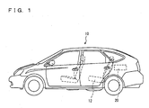
- drive-purpose power supply unit 20 supplying power to a motor for driving vehicle 10 is mounted, behind a rear seat 12 and above a luggage room floor.
- the present invention is not limited thereto.
- the cooled air may be suctioned from the side of the rear seat, or from above or below the rear seat. Also, the air can be emitted into the cabin.
- Fig. 3 is a partial enlarged view of Fig. 1 . In Fig. 3 , only the rear portion of vehicle 10 including rear seat 12 is shown.
- Fig. 3 shows a cooling apparatus 1000 for drive-purpose power supply unit 20 according to the embodiment of the present invention is shown.
- cooling apparatus 1000 is arranged in a luggage room located on the rear side in the vehicle relative to an in-cabin space (a space for occupants) 2000 (it is to be noted that the luggage room is a space except for the space for occupants).
- Cooling apparatus 1000 is arranged at substantially the center in the vehicular width direction so as not to interfere with tire houses 200 on the opposing sides in the vehicular width direction.
- Cooling apparatus 1000 includes a battery 1010 that can be charged and discharged and that is a drive source of the vehicle, a battery cooling fan 1012, a DC/DC converter 1020, and a DC/DC converter cooling fan 1022.
- Battery 1010 is constituted of, for example as described above, a battery pack, which is constituted of multiple (twenty to thirty) battery modules connected in series, each battery module being constituted of six prismatic battery cells (each having normally an output voltage of about 1.2V) connected in series. Battery 1010 has a size that allows battery 1010 to be stored inside a rear side member in the vehicular width direction.
- Cooling apparatus 1000 suctions the air in in-cabin space 2000 from a suction inlet 1030 via a duct 1032 by battery cooling fan 1012 and/or DC/DC converter cooling fan 1022, and thereby cools battery 1010 and/or DC/DC converter 1020.
- duct 1032 branches into a battery-side duct 1034 and a DC/DC converter-side duct 1036.
- Battery 1010 is installed downstream from battery-side duct 1034, and DC/DC converter cooling fan 1022 is installed downstream from DC/DC converter-side duct 1036.
- DC/DC converter 1020 is installed downstream from DC/DC converter cooling fan 1022.
- the air discharged from battery 1010 passes through a battery-side exhaust duct 1038, while the air discharged from DC/DC converter 1020 passes through DC/DC converter-side exhaust duct 1040. Thereafter, they merge into each other and discharged to the outside of the vehicle from a discharge outlet 1050.
- Suction inlet 1030 opens to a rear package tray (a member where normally a speaker of audio equipment or the like is installed) positioned at a portion below a rear glass 2200. That is, as duct 1032 is arranged to extend from above to below as shown in Fig. 3 , the in-cabin air flows from above to below as represented by the arrow in Fig. 3 . The in-cabin air is suctioned by battery cooling fan 1012 toward battery 1010 (and flows through battery modules). Thereafter, the air having cooled battery 1010 is discharged from discharge outlet 1050 formed behind battery 1010 to the outside of the vehicle.
- a rear package tray a member where normally a speaker of audio equipment or the like is installed
- the in-cabin air flows from above to below as represented by the arrow in Fig. 3 , then it is suctioned toward DC/DC converter 1020, and flows through the cooling fins abutted on a substrate of DC/DC converter 1020. Thereafter, the air having cooled DC/DC converter 1020 is discharged from discharge outlet 1050 formed behind DC/DC converter 1020 to the outside of the vehicle.
- Fig. 4 is a schematic developed view of battery 1010 in Fig. 3 .
- Fig. 5 is a schematic perspective view of the battery modules constituting battery 1010 in Fig. 4 .
- battery 1010 is structured to have a battery pack 2120 stored inside an exterior member constituted of a battery cover 2102 and a lower case 2122.
- Battery pack 2120 is formed with a plurality of battery modules 2130 as stacked.
- Battery module 2130 has an outer shape of what is called a prismatic plate type.
- Battery module 2130 includes a plurality of battery cells. Specifically, as shown in Fig. 5 , battery module 2130 includes a prismatic case 2138 that is one unit and that is a module exterior member, and six battery cells 2140-2150 divided by walls inside prismatic case 2138. On an end face of prismatic case 2138 in the longitudinal direction, a terminal 2128 is formed. On the side face of prismatic case 2138, protrusions 2152 for forming gaps as passages for cooling air between each of battery modules 2130 are formed. In battery pack 2120 (see Fig.
- Battery cells 2140-2150 are basically structured similarly to each other. Taking a first battery cell 2140 as an example, battery cell 2140 is constituted of a stacked electrode body 2154, constituted of, for example, a plurality of alternately stacked sheet-like electrode members insulated by separators, and a pair of collector plates 2156 arranged so that stacked electrode body 2154 is interposed therebetween. It is to be noted that stacked electrode body 2154 has been subjected to impregnation or injection of electrolyte.
- stacked electrode body 2154 electrode members to be cathode and electrode members to be anode are alternately stacked.
- the electrode members to be cathode have their ends connected together to one collector plate 2156.
- the electrode members to be anode have their ends connected together to the other collector plate (not shown).
- all the electrode members to be cathode and one collector plate 2156 are electrically connected.
- all the electrode members to be anode and the other collector plate are electrically connected.
- Battery cells 2140-2150 included in battery module 2130 are electrically connected in series. For example, when battery cells 140-150 each have a rated voltage of 1.2V, the rated voltage of the whole battery module 2130 is 7.2V.
- the configuration of battery cells 2140-2150 is not limited to the configuration described above, and may be any other configuration.
- binding plates 2116, 2118 are arranged at the opposing ends of battery pack 2120. Binding plates 2116, 2118 are connected and fixed to each other by binding pipes 2108, 2110. Binding plates 2116, 2118 are fixed to a lower case 2122. Each of battery modules 2130 is also fixed to lower case 2122.
- terminal 2128 for input and output of current to and from battery module 2130 is formed on the side face (end face) of each of battery modules 2130 constituting battery pack 2120.
- bus bar modules 2112, 2114 are arranged on the side face of battery pack 2120.
- bus bar modules 2112, 2114 are electrically connected in series in battery pack 2120.
- exhaust terminals 2126 including a safety valve for collectively discharging hydrogen gas and the like exhausted from battery modules 2130 are formed.
- an exhaust hose 2104 connected to exhaust terminals 2126 for discharging hydrogen gas discharged from battery modules 2130 to the outside of battery 1010 is arranged.
- a temperature sensor 2124 for measuring the temperature of battery pack 2120 and a harness are arranged. In accordance with the output of temperature sensor 2124, cooling air is supplied from inside the cabin to battery pack 2120 using battery cooling fan 1012, in order to maintain the temperature of battery pack 2120 within a prescribed range.
- protrusions 2152 As battery module 2130 has protrusions 2152, when battery modules 2130 are arranged next to each other as shown in Fig. 4 , protrusions 2152 produce gaps between each of battery modules 2130. Cooling air is allowed to flow through the gaps from above battery modules 2130 to below thereof (the downflow scheme). This cooling air cools battery modules 2130.
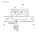
- Fig. 6 is a schematic developed view of DC/DC converter 1020 in Fig. 3 .
- DC/DC converter 1020 is constituted of a semiconductor device 3030, a transformer 3040 and a substrate 3050, which are covered by an electromagnetic shield cover 3010.
- semiconductor device 3030 and transformer 3040 that emit a great amount of heat are arranged to abut on cooling fin 3020.
- Cooling air is introduced from DC/DC converter-side intake duct 1036 toward cooling fin 3020.
- the cooling air having deprived cooling fin 3020 of heat passes through DC/DC converter-side exhaust duct 1040, and discharged from discharge outlet 1050 to the outside of the vehicle.
- the material of cooling fin 3020 is of high thermal conductivity.
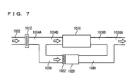
- Fig. 7 is a schematic view of the structure of cooling apparatus 1000 shown in Fig. 3 .
- Battery-side intake duct 1034 is constituted of a battery-side intake duct 1034A before DC/DC converter-side intake duct 1036 branches therefrom, and a battery-side intake duct 1034B after DC/DC converter-side intake duct 1036 branches therefrom.
- Battery-side exhaust duct 1038 is constituted of a battery-side exhaust duct 1038B before merging into DC/DC converter-side exhaust duct 1040 and a battery-side exhaust duct 1038A after merging into DC/DC converter-side exhaust duct 1040.
- the remainder of the structure is the same as in Fig. 3 described above, and therefore detailed description thereof is not repeated.
- the resistance of the pipe line of intake ducts and exhaust ducts can be made small, and the pressure loss of the cooling air can be reduced. Accordingly, the rated capacity (defined by the discharge flow rate and the discharge pressure) of the cooling fans can be reduced, and the power consumption can be reduced.
- Fig. 8 is a control block diagram of cooling apparatus 1000 according to the embodiment of the present invention. As shown in Fig. 8 , cooling apparatus 1000 is controlled by an ECU (Electronic Control Unit) 4000.
- ECU Electronic Control Unit
- Battery 1010 is provided with a battery temperature sensor 4012 sensing the temperature (representative temperature) of battery 1010.
- Battery temperature sensor 4012 corresponds to temperature sensor 2124 shown in Fig. 4 .
- DC/DC converter 1020 is provided with an on-substrate thermistor 4022 on substrate 3050 for sensing the temperature of DC/DC converter 1020.
- Battery temperature sensor 4012 and on-substrate thermistor 4022 are connected to ECU 4000, and respectively transmit the battery temperature and the DC/DC converter temperature to ECU 4000. Based on the temperatures, ECU 4000 outputs motor drive command signals respectively for controlling a battery cooling fan motor 4040 driving battery cooling fan 1012 and DC/DC converter cooling fan motor 4050 driving DC/DC converter cooling fan 1022. It may be also possible to control continuously or stepwise the rotation speed of battery cooling fan motor 4040 and DC/DC converter cooling fan motor 4050 by voltage control or current control. This allows ECU 4000 to control the characteristics (flow rate characteristics, pressure characteristics) of battery cooling fan 1012 and DC/DC converter cooling fan 1022. It is assumed that battery cooling fan 1012 is greater than DC/DC converter cooling fan 1022 in rated capacity (and also in discharge flow rate and discharge pressure).
- Fig. 9 a control structure of a program executed by ECU 4000 in Fig. 8 is described.
- the program represented by the flowchart of Fig. 9 is repeatedly executed at regular intervals (cycle time), once the ignition switch enters a state corresponding to the start of activation of the HV system.
- step (hereinafter step is expressed by S) 100 the temperature of battery 1010 and the temperature on substrate 3050 representing the temperature of DC/DC converter 1020 are sensed.
- ECU 4000 senses respective temperatures based on an input signal from battery temperature sensor 4012 and an input signal from on-substrate thermistor 4022.
- ECU 4000 determines whether or not the on-substrate temperature is higher than a temperature threshold value (1).
- a temperature threshold value (1) YES in S200
- the process proceeds to S300. Otherwise (NO in S200), the process proceeds to S400.
- ECU 4000 In S300, ECU 4000 outputs a drive command to DC/DC converter cooling fan motor 4050.
- DC/DC converter cooling fan 1022 operates and the cooling air is supplied from the cabin to DC/DC converter 1020 only.
- ECU 4000 determines whether or not the battery temperature is higher than a temperature threshold value (2), or whether or not the on-substrate temperature is higher than a temperature threshold value (3). It is to be noted that temperature threshold value (3) is set to be higher than temperature threshold value (1). When the battery temperature is higher than temperature threshold value (2) or the on-substrate temperature is higher than temperature threshold value (3) (YES in S400), the process proceeds to S500. Otherwise (NO in S400), the process ends.
- ECU 4000 In S500, ECU 4000 outputs a drive command to battery cooling fan motor 4040.
- battery cooling fan 1012 operates and the cooling air is supplied from inside the cabin to battery 1010 and DC/DC converter 1020.
- cooling apparatus 1000 An operation of cooling apparatus 1000 according to the embodiment of the present invention based on the above-described structure and flowchart will be described. It is assumed that, by the setting of temperature threshold value (1), temperature threshold value (2), and temperature threshold value (3), a state occurs where a cooling request from DC/DC converter 1020 is present and cooling request from battery 1010 is not present.
- the battery temperature and the on-substrate temperature are sensed (S100).
- the on-substrate temperature of DC/DC converter 1020 is higher than temperature threshold value (1) (YES in S200), and the temperature of battery 1010 is not higher than temperature threshold value (2) (YES in S400), it is determined that it is a state where "a cooling request from battery 1010 is not present and a cooling request from DC/DC converter 1020 is present". It is assumed that the on-substrate temperature of DC/DC converter 1020 is not higher than temperature threshold value (3).
- a drive command is output to DC/DC converter cooling fan motor 4050 so that only DC/DC converter cooling fan 1022 having a small rated capacity operates (S300).
- battery cooling fan 1010 does not operate.
- DC/DC converter 1020 when only DC/DC converter 1020 requests cooling, which has a great amount of heat emission as compared to battery 1010 and the heat emission greatly fluctuates in accordance with the drive state of the vehicle, DC/DC converter 1020 can appropriately be cooled using only DC/DC converter cooling fan 1022 having a small rated capacity.
- a drive command is output to DC/DC converter cooling fan motor 4050 (5300), and also a drive command is output to battery cooling fan motor 4040 (S500), so that battery cooling fan 1010 having a great rated capacity operates in addition to DC/DC converter cooling fan 1022 having a small rated capacity. Accordingly, battery cooling fan 1010 and DC/DC converter cooling fan 1022 operate here.
- DC/DC converter 1020 when DC/DC converter 1020 further requests cooling, which has a great amount of heat emission as compared to battery 1010 and the heat emission greatly fluctuates in accordance with the drive state of the vehicle, in addition to DC/DC converter cooling fan 1022 having a small rated capacity, battery cooling fan 1012 having a great rated capacity is operated, so that the cooling air of a great flow rate is sent to DC/DC converter 1020 to sufficiently cool DC/DC converter 1020.
- the flow of cooling air to battery 1010 is established by the operation of battery cooling fan 1012, DC/DC converter cooling fan 1022 is operating. Therefore, the pressure in the intake duct on DC/DC converter 1020 side is low, and the cooling air flows through DC/DC converter 1020 in greater amount.
- DC/DC converter 1020 requesting further cooling can appropriately be cooled.
- two cooling fans are connected in series.
- a drive command is output to DC/DC converter cooling fan motor 4050 (S300), and also a drive command is output to battery cooling fan motor 4040 (S500), so that battery cooling fan 1010 having a great rated capacity operates in addition to DC/DC converter cooling fan 1022 having a small rated capacity. Accordingly, battery cooling fan 1010 and DC/DC converter cooling fan 1022 operate here.
- battery cooling fan 1012 having a great rated capacity is operated, so that the cooling air of a great flow rate is sent to battery 1010 and DC/DC converter 1020 to sufficiently cool battery 1010 and DC/DC converter 1020.
- the rated capacity of DC/DC converter cooling fan 1022 is smaller than that of battery cooling fan 1010, a situation can be avoided where the cooling air sent by battery cooling fan 1012 is entirely suctioned by DC/DC converter cooling fan 1022 and sent only to DC/DC converter 1020 whereby cooling air for battery 1010 becomes insufficient.
- the rated capacity of DC/DC converter cooling fan 1022 is greater than that of battery cooling fan 1010, the cooling air sent by battery cooling fan 1012 (small rated capacity) may entirely be suctioned by DC/DC converter cooling fan 1022 (great rated capacity).
- cooling apparatus of the embodiment of the present invention when branched intake passages are provided to cool two types of cooling targets (the battery and the DC/DC converter), two cooling fans having different rated capacity are respectively arranged before and after the branching portion of the intake passages.
- the cooling fan having the smaller rated capacity is arranged in the intake passage after branched toward the cooling target of which cooling request would become greater.
- the two cooling fans are operated to send the cooling air.
- the two cooling fans are operated, two cooling targets can appropriately be cooled while a situation where only one of them is supplied with the cooling air is avoided, since the two cooling fans have different rated capacity and the one having the smaller rated capacity is arranged after the branch.
- DC/DC converter 1020 and DC/DC converter cooling fan 1022 may integrally be configured. With such a configuration, the control substrate of DC/DC converter cooling fan motor 4050 can be incorporated into the substrate of DC/DC converter 1020. Furthermore, in addition to such integration, if DC/DC converter 1020 and DC/DC converter cooling fan 1022 are sealed, leakage of air can be eliminated and the cooling capacity can be improved.
Landscapes
- Engineering & Computer Science (AREA)
- Chemical & Material Sciences (AREA)
- Chemical Kinetics & Catalysis (AREA)
- Electrochemistry (AREA)
- General Chemical & Material Sciences (AREA)
- Manufacturing & Machinery (AREA)
- Transportation (AREA)
- Mechanical Engineering (AREA)
- Combustion & Propulsion (AREA)
- Power Engineering (AREA)
- Automation & Control Theory (AREA)
- Life Sciences & Earth Sciences (AREA)
- Sustainable Development (AREA)
- Sustainable Energy (AREA)
- Electric Propulsion And Braking For Vehicles (AREA)
- Secondary Cells (AREA)
- Cooling, Air Intake And Gas Exhaust, And Fuel Tank Arrangements In Propulsion Units (AREA)
Applications Claiming Priority (2)
| Application Number | Priority Date | Filing Date | Title |
|---|---|---|---|
| JP2005293655A JP4274165B2 (ja) | 2005-10-06 | 2005-10-06 | 車両搭載機器の冷却装置 |
| PCT/JP2006/319233 WO2007043341A1 (ja) | 2005-10-06 | 2006-09-21 | 車両搭載機器の冷却装置 |
Publications (3)
| Publication Number | Publication Date |
|---|---|
| EP1932707A1 true EP1932707A1 (de) | 2008-06-18 |
| EP1932707A4 EP1932707A4 (de) | 2012-02-22 |
| EP1932707B1 EP1932707B1 (de) | 2012-12-05 |
Family
ID=37942590
Family Applications (1)
| Application Number | Title | Priority Date | Filing Date |
|---|---|---|---|
| EP06810691A Expired - Fee Related EP1932707B1 (de) | 2005-10-06 | 2006-09-21 | Kühlvorrichtung für maschinen im fahrzeug |
Country Status (7)
| Country | Link |
|---|---|
| US (1) | US7900727B2 (de) |
| EP (1) | EP1932707B1 (de) |
| JP (1) | JP4274165B2 (de) |
| KR (1) | KR100942558B1 (de) |
| CN (2) | CN101282852B (de) |
| CA (1) | CA2624804C (de) |
| WO (1) | WO2007043341A1 (de) |
Cited By (16)
| Publication number | Priority date | Publication date | Assignee | Title |
|---|---|---|---|---|
| EP2357104A1 (de) * | 2008-11-17 | 2011-08-17 | Honda Motor Co., Ltd. | Kühlstruktur für eine fahrzeugstromquelleneinheit |
| WO2012032271A1 (fr) * | 2010-09-09 | 2012-03-15 | Peugeot Citroën Automobiles SA | Vehicule automobile comportant un circuit de refroidissement d'un module d'alimentation electrique |
| DE102011116126A1 (de) | 2011-10-15 | 2012-05-24 | Daimler Ag | Batterie mit außenseitig an einem Batteriegehäuseangeordneten elektrischen und/oder elektronischenKomponenten |
| EP2518815A1 (de) * | 2011-04-25 | 2012-10-31 | LG Chem, Ltd. | Batteriesystem und Verfahren zur Verlängerung der Lebensdauer einer Batteriezelle |
| RU2496658C1 (ru) * | 2009-08-03 | 2013-10-27 | Хонда Мотор Ко., Лтд. | Охлаждающая структура для высоковольтных электрических частей транспортного средства |
| EP2669107A1 (de) * | 2011-01-27 | 2013-12-04 | Toyota Jidosha Kabushiki Kaisha | Kühlvorrichtung |
| RU2505425C1 (ru) * | 2009-12-14 | 2014-01-27 | Хонда Мотор Ко., Лтд. | Охлаждающая конструкция для устройства накопления электроэнергии |
| EP2772394A4 (de) * | 2011-10-24 | 2015-06-17 | Honda Motor Co Ltd | Verdrahtungsschutzabdeckungsstruktur für ein elektrofahrzeug |
| WO2015189491A1 (fr) * | 2014-06-12 | 2015-12-17 | Peugeot Citroen Automobiles Sa | Méthode de contrôle de température d'une unité électrique de véhicule automobile |
| EP3142183A4 (de) * | 2014-09-18 | 2017-11-29 | LG Chem, Ltd. | Batteriepack und verfahren zur steuerung eines elektrischen lüfters für ein batteriepack |
| EP3267510A1 (de) * | 2016-07-07 | 2018-01-10 | HOPPECKE Batterien GmbH & Co. KG | Traktionsbatterie |
| WO2018185074A1 (de) * | 2017-04-04 | 2018-10-11 | Hoppecke Batterien Gmbh & Co. Kg | Traktionsbatterie |
| US10141618B2 (en) | 2015-07-15 | 2018-11-27 | Hyundai Motor Company | System and method of cooling high voltage battery |
| DE102018000151A1 (de) * | 2018-01-11 | 2019-07-11 | Audi Ag | Anzeigevorrichtungsanordnung für ein Fahrzeug |
| FR3084526A1 (fr) * | 2018-07-26 | 2020-01-31 | Psa Automobiles Sa | Systeme de refroidissement d’une batterie de reseau de bord au lithium-ion |
| DE102016200600B4 (de) | 2015-01-23 | 2022-06-09 | Suzuki Motor Corporation | Kühlmechanismus für einen Batteriepack zur Verwendung in Fahrzeugen |
Families Citing this family (73)
| Publication number | Priority date | Publication date | Assignee | Title |
|---|---|---|---|---|
| WO2006042648A1 (de) * | 2004-10-15 | 2006-04-27 | Behr Gmbh & Co. Kg | Lüftersystem für ein kraftfahrzeug |
| JP4297105B2 (ja) * | 2005-10-14 | 2009-07-15 | トヨタ自動車株式会社 | 蓄電装置の冷却構造 |
| JP4857896B2 (ja) * | 2006-05-11 | 2012-01-18 | トヨタ自動車株式会社 | 組電池および車両 |
| JP4715708B2 (ja) * | 2006-10-03 | 2011-07-06 | トヨタ自動車株式会社 | 電動車両および車両充電システム |
| JP4390802B2 (ja) * | 2006-12-15 | 2009-12-24 | トヨタ自動車株式会社 | 車載バッテリ冷却構造 |
| US8006626B2 (en) * | 2007-05-07 | 2011-08-30 | General Electric Company | System and method for cooling a battery |
| US8720344B2 (en) * | 2007-05-07 | 2014-05-13 | General Electric Company | Thermal management system and method |
| JP5009096B2 (ja) * | 2007-08-29 | 2012-08-22 | 本田技研工業株式会社 | 電気自動車 |
| JP4957492B2 (ja) * | 2007-09-28 | 2012-06-20 | 三菱自動車工業株式会社 | 電気自動車のバッテリーユニット冷却用ダクト構造 |
| JP5029263B2 (ja) * | 2007-09-28 | 2012-09-19 | 三菱自動車工業株式会社 | 電気自動車 |
| KR20090062380A (ko) * | 2007-12-13 | 2009-06-17 | 현대자동차주식회사 | 하이브리드 배터리시스템의 출구덕트 |
| TWI338642B (en) * | 2008-02-07 | 2011-03-11 | Honda Motor Co Ltd | Vehicular power supply system |
| JP2009274651A (ja) * | 2008-05-16 | 2009-11-26 | Toyota Industries Corp | ハイブリッド産業車両 |
| JP5340659B2 (ja) * | 2008-07-07 | 2013-11-13 | 三洋電機株式会社 | 車両用の組電池 |
| EP2314537B1 (de) * | 2008-08-19 | 2013-01-16 | Mitsubishi Heavy Industries, Ltd. | Batteriekühlstruktur für ein industrielles hybridfahrzeug |
| JP4478900B1 (ja) | 2008-12-03 | 2010-06-09 | 本田技研工業株式会社 | 蓄電器加温装置 |
| JP5131182B2 (ja) * | 2008-12-24 | 2013-01-30 | トヨタ自動車株式会社 | 蓄電モジュールの温度調節構造 |
| FR2940632B1 (fr) * | 2008-12-30 | 2011-08-19 | Renault Sas | Dispositif pour refroidir les batteries d'un vehicule notamment electrique et vehicule equipe d'un tel dispositif |
| FR2948231B1 (fr) * | 2009-07-17 | 2013-01-18 | Peugeot Citroen Automobiles Sa | Vehicule automobile comportant un moteur electrique alimente par un module d'alimentation |
| JP5024353B2 (ja) * | 2009-10-29 | 2012-09-12 | トヨタ自動車株式会社 | 電気機器の冷却システム |
| WO2011061571A1 (en) * | 2009-11-18 | 2011-05-26 | Hydro Aluminium Alunord | Battery tray for vehicle and method for producing the battery tray |
| DE102010007633A1 (de) * | 2010-02-05 | 2011-08-11 | Dr. Ing. h.c. F. Porsche Aktiengesellschaft, 70435 | Fahrzeug mit elektrischer Antriebsvorrichtung |
| JP5362629B2 (ja) | 2010-03-18 | 2013-12-11 | カルソニックカンセイ株式会社 | 発熱体冷却装置 |
| US8662968B2 (en) * | 2010-04-30 | 2014-03-04 | GM Global Technology Operations LLC | Air-based hybrid battery thermal conditioning system |
| US8662226B2 (en) * | 2010-06-08 | 2014-03-04 | Ford Global Technologies, Llc | Apparatus for heating a vehicle cabin |
| US8276696B2 (en) * | 2010-07-27 | 2012-10-02 | Ford Global Technologies, Llc | Structural battery duct assembly |
| JP5198522B2 (ja) | 2010-08-31 | 2013-05-15 | トヨタ自動車株式会社 | 蓄電装置および車両 |
| US8960350B2 (en) * | 2010-08-31 | 2015-02-24 | Toyota Jidosha Kabushiki Kaisha | Vehicle and electric storage apparatus |
| JP5565234B2 (ja) * | 2010-09-21 | 2014-08-06 | スズキ株式会社 | 車両のバッテリ排気装置 |
| KR101219820B1 (ko) * | 2010-09-27 | 2013-01-08 | 기아자동차주식회사 | 차량의 배터리 냉각 장치 및 그 제어방법 |
| US20130181516A1 (en) * | 2010-10-05 | 2013-07-18 | Taing Foung Phan | Battery augmentation system and method |
| KR101180954B1 (ko) * | 2010-12-03 | 2012-09-07 | 기아자동차주식회사 | 자동차의 고전압 배터리 냉각 시스템 |
| EP2648930B1 (de) | 2010-12-07 | 2019-11-06 | Allison Transmission, Inc. | Energiespeichersystem für ein elektrisches hybridfahrzeug |
| US8950533B2 (en) | 2011-01-31 | 2015-02-10 | GM Global Technology Operations LLC | Cooling arrangement for a component in a vehicle |
| US9141117B2 (en) * | 2011-05-04 | 2015-09-22 | GM Global Technology Operations LLC | Thermal control of multiple devices |
| KR101283229B1 (ko) * | 2011-06-16 | 2013-07-11 | 기아자동차주식회사 | 친환경자동차의 배터리 냉각구조 |
| CN103036259A (zh) * | 2011-09-29 | 2013-04-10 | 中兴电工机械股份有限公司 | 能量调节方法 |
| WO2013073465A1 (ja) * | 2011-11-14 | 2013-05-23 | 本田技研工業株式会社 | 電動車両用バッテリパックおよびバッテリパックの搭載構造 |
| US9240750B2 (en) * | 2011-11-30 | 2016-01-19 | Mitsubishi Electric Corporation | Forced air cooling-type power conversion device |
| US20140335771A1 (en) * | 2011-12-09 | 2014-11-13 | Toyota Jidosha Kabushiki Kaisha | Cooling device for power storage device and cooling control method for power storage device |
| US20140338999A1 (en) * | 2011-12-09 | 2014-11-20 | Honda Motor Co., Ltd. | Structure for mounting battery pack on vehicle |
| US9247775B2 (en) | 2012-01-23 | 2016-02-02 | Daio Paper Corporation | Mask |
| US20130228387A1 (en) * | 2012-01-24 | 2013-09-05 | Ford Global Technologies, Llc | Drive Battery Arrangement and Motor Vehicle Having a Drive Battery Arrangement |
| JP5983054B2 (ja) * | 2012-06-04 | 2016-08-31 | スズキ株式会社 | ハイブリッド自動車のバッテリパック冷却構造 |
| US8978803B2 (en) | 2012-06-11 | 2015-03-17 | GM Global Technology Operations LLC | Divided dual inlet housing for an air-based hybrid battery thermal conditioning system |
| US9300017B2 (en) * | 2012-08-03 | 2016-03-29 | Ford Global Technologies, Llc | Detecting blockage of air flow through vehicle traction battery |
| US9174520B2 (en) * | 2012-10-31 | 2015-11-03 | Honda Motor Co., Ltd. | Electric vehicle |
| JP5902078B2 (ja) * | 2012-11-08 | 2016-04-13 | 本田技研工業株式会社 | 電動車両 |
| JP5827615B2 (ja) * | 2012-12-27 | 2015-12-02 | トヨタ紡織株式会社 | 車両用排気構造 |
| CN105050864B (zh) * | 2013-04-05 | 2018-05-18 | 日产自动车株式会社 | 汽车的发热电气零件的配设构造 |
| WO2014203374A1 (ja) * | 2013-06-20 | 2014-12-24 | 三菱電機株式会社 | 車両用の電力変換装置 |
| US10106025B2 (en) * | 2013-08-29 | 2018-10-23 | Ford Global Technologies, Llc | High voltage battery cooling plenum |
| JP2015177708A (ja) * | 2014-03-18 | 2015-10-05 | 株式会社日立製作所 | 電源装置 |
| JP2015186362A (ja) * | 2014-03-25 | 2015-10-22 | 株式会社日立製作所 | 電源装置 |
| CN104701586B (zh) * | 2014-12-31 | 2017-03-08 | 浙江吉利汽车研究院有限公司 | 一种车载电池包风道冷却系统 |
| US10326183B2 (en) | 2015-02-05 | 2019-06-18 | Honda Motor Co., Ltd. | Vehicle power supply system |
| US10399455B2 (en) * | 2015-03-06 | 2019-09-03 | Honda Motor Co., Ltd. | Vehicle high-voltage system equipment unit, vehicle battery unit and vehicle |
| CN104735961B (zh) * | 2015-03-12 | 2017-07-11 | 广东亿纬赛恩斯新能源系统有限公司 | 电控部件的防水散热结构及具有防水散热结构的电动车 |
| US9979056B2 (en) | 2015-09-22 | 2018-05-22 | Ford Global Technologies, Llc | Battery pack flow control system with fan assembly |
| US9985325B2 (en) | 2015-09-22 | 2018-05-29 | Ford Global Technologies, Llc | Battery pack flow control method |
| JP6534334B2 (ja) * | 2015-10-20 | 2019-06-26 | 本田技研工業株式会社 | 車両 |
| JP6535570B2 (ja) * | 2015-10-20 | 2019-06-26 | 本田技研工業株式会社 | 車両 |
| KR101631237B1 (ko) * | 2015-12-22 | 2016-06-17 | 주식회사 이알인터내셔널 | 운행차용 고전압 발전 제어 시스템 |
| JP6589655B2 (ja) * | 2016-01-21 | 2019-10-16 | トヨタ自動車株式会社 | 冷却装置 |
| FR3048929B1 (fr) * | 2016-03-15 | 2020-03-27 | Institut Vedecom | Vehicule a moteur electrique commande par un module de puissance et systeme de refroidissement d’un tel module de puissance |
| CN105811045B (zh) * | 2016-05-05 | 2019-11-05 | 观致汽车有限公司 | 车辆电池装置 |
| JP6311744B2 (ja) * | 2016-06-06 | 2018-04-18 | トヨタ自動車株式会社 | 空冷式燃料電池車 |
| JP6465082B2 (ja) * | 2016-07-29 | 2019-02-06 | トヨタ自動車株式会社 | 車両構造 |
| US10391864B2 (en) * | 2017-02-08 | 2019-08-27 | Toyota Motor Engineering & Manufacturing North America, Inc. | System to balance high voltage battery for vehicle |
| JP7047419B2 (ja) * | 2018-02-01 | 2022-04-05 | トヨタ自動車株式会社 | 車両用クーラ装置 |
| JP7212526B2 (ja) * | 2019-01-15 | 2023-01-25 | 株式会社Subaru | 冷却システム |
| JP7316167B2 (ja) * | 2019-09-25 | 2023-07-27 | 株式会社Subaru | 車両用バッテリパック |
| US20230031346A1 (en) * | 2021-07-29 | 2023-02-02 | Rivian Ip Holdings, Llc | Heating, ventilation, and air conditioning case with extractor port to ambient |
Citations (3)
| Publication number | Priority date | Publication date | Assignee | Title |
|---|---|---|---|---|
| JPH11185831A (ja) * | 1997-10-13 | 1999-07-09 | Denso Corp | バッテリ装置 |
| US5937664A (en) * | 1997-03-05 | 1999-08-17 | Toyota Jidosha Kabushiki Kaisha | Battery cooling system for vehicle |
| EP1538885A2 (de) * | 2003-11-26 | 2005-06-08 | HONDA MOTOR CO., Ltd. | Kühleinrichtung für eine elektrische Hochspannungseinheit für Kraftfahrzeuge, und Hybridfahrzeug |
Family Cites Families (24)
| Publication number | Priority date | Publication date | Assignee | Title |
|---|---|---|---|---|
| JP3125198B2 (ja) * | 1991-12-04 | 2001-01-15 | 本田技研工業株式会社 | 電気自動車におけるバッテリ温度制御装置 |
| JPH0747846A (ja) | 1993-08-09 | 1995-02-21 | Honda Motor Co Ltd | 電気自動車のモータ制御装置下面冷却構造 |
| US6220383B1 (en) * | 1997-10-13 | 2001-04-24 | Denso Corporation | Electric power unit |
| JPH11164401A (ja) * | 1997-11-28 | 1999-06-18 | Yazaki Corp | 電気自動車用電池管理装置 |
| JP3509517B2 (ja) * | 1997-12-18 | 2004-03-22 | 本田技研工業株式会社 | 電気自動車におけるバッテリおよび電気部品の冷却構造 |
| JP2001283803A (ja) * | 2000-03-31 | 2001-10-12 | Matsushita Electric Ind Co Ltd | 電動車輌に用いる組電池システム |
| JP3777981B2 (ja) * | 2000-04-13 | 2006-05-24 | トヨタ自動車株式会社 | 車両用電源装置 |
| JP3986242B2 (ja) | 2000-09-07 | 2007-10-03 | 三洋電機株式会社 | 電気自動車用バッテリシステム |
| JP4224669B2 (ja) | 2001-09-25 | 2009-02-18 | スズキ株式会社 | ハイブリッド自動車のバッテリー搭載装置 |
| JP3652634B2 (ja) * | 2001-10-05 | 2005-05-25 | 本田技研工業株式会社 | 高圧電装部品の冷却構造 |
| JP3843956B2 (ja) | 2002-05-14 | 2006-11-08 | トヨタ自動車株式会社 | 車載バッテリのファン制御方法およびファン制御装置 |
| JP2004306726A (ja) | 2003-04-04 | 2004-11-04 | Toyota Motor Corp | バッテリパック冷却構造 |
| JP4395316B2 (ja) | 2003-04-16 | 2010-01-06 | パナソニックEvエナジー株式会社 | 電池パック |
| JP4374925B2 (ja) | 2003-06-26 | 2009-12-02 | トヨタ自動車株式会社 | バッテリパックの冷却構造 |
| JP4519516B2 (ja) * | 2003-07-15 | 2010-08-04 | 本田技研工業株式会社 | 車両用電装ユニットの加温冷却装置およびハイブリッド車両 |
| JP2005063689A (ja) | 2003-08-12 | 2005-03-10 | Nissan Motor Co Ltd | バッテリ冷却制御装置 |
| KR100527445B1 (ko) * | 2003-09-16 | 2005-11-09 | 현대자동차주식회사 | 연료전지 차량의 냉각 시스템 |
| JP2005160132A (ja) | 2003-11-20 | 2005-06-16 | Toyota Motor Corp | 冷却装置の異常判定装置 |
| JP4042694B2 (ja) * | 2003-12-26 | 2008-02-06 | トヨタ自動車株式会社 | 蓄電機構の冷却装置 |
| JP4096885B2 (ja) | 2004-02-02 | 2008-06-04 | トヨタ自動車株式会社 | 車両に搭載された電力変換機構の冷却装置 |
| JP4626161B2 (ja) | 2004-03-04 | 2011-02-02 | トヨタ自動車株式会社 | 車両に搭載された電気機器の冷却装置 |
| JP2005318675A (ja) | 2004-04-27 | 2005-11-10 | Toyota Motor Corp | 電気システム |
| JP4576931B2 (ja) * | 2004-08-27 | 2010-11-10 | トヨタ自動車株式会社 | 電気機器の搭載構造 |
| US7353900B2 (en) * | 2004-09-21 | 2008-04-08 | Nissan Motor Co., Ltd. | Battery cooling system |
-
2005
- 2005-10-06 JP JP2005293655A patent/JP4274165B2/ja active Active
-
2006
- 2006-09-21 KR KR1020087010740A patent/KR100942558B1/ko active IP Right Grant
- 2006-09-21 CN CN2006800371768A patent/CN101282852B/zh not_active Expired - Fee Related
- 2006-09-21 EP EP06810691A patent/EP1932707B1/de not_active Expired - Fee Related
- 2006-09-21 US US11/992,944 patent/US7900727B2/en not_active Expired - Fee Related
- 2006-09-21 WO PCT/JP2006/319233 patent/WO2007043341A1/ja active Application Filing
- 2006-09-21 CA CA2624804A patent/CA2624804C/en not_active Expired - Fee Related
- 2006-09-21 CN CN2010102739452A patent/CN101934724B/zh not_active Expired - Fee Related
Patent Citations (3)
| Publication number | Priority date | Publication date | Assignee | Title |
|---|---|---|---|---|
| US5937664A (en) * | 1997-03-05 | 1999-08-17 | Toyota Jidosha Kabushiki Kaisha | Battery cooling system for vehicle |
| JPH11185831A (ja) * | 1997-10-13 | 1999-07-09 | Denso Corp | バッテリ装置 |
| EP1538885A2 (de) * | 2003-11-26 | 2005-06-08 | HONDA MOTOR CO., Ltd. | Kühleinrichtung für eine elektrische Hochspannungseinheit für Kraftfahrzeuge, und Hybridfahrzeug |
Non-Patent Citations (1)
| Title |
|---|
| See also references of WO2007043341A1 * |
Cited By (24)
| Publication number | Priority date | Publication date | Assignee | Title |
|---|---|---|---|---|
| EP2357104A1 (de) * | 2008-11-17 | 2011-08-17 | Honda Motor Co., Ltd. | Kühlstruktur für eine fahrzeugstromquelleneinheit |
| EP2357104A4 (de) * | 2008-11-17 | 2013-04-17 | Honda Motor Co Ltd | Kühlstruktur für eine fahrzeugstromquelleneinheit |
| RU2496658C1 (ru) * | 2009-08-03 | 2013-10-27 | Хонда Мотор Ко., Лтд. | Охлаждающая структура для высоковольтных электрических частей транспортного средства |
| RU2505425C1 (ru) * | 2009-12-14 | 2014-01-27 | Хонда Мотор Ко., Лтд. | Охлаждающая конструкция для устройства накопления электроэнергии |
| WO2012032271A1 (fr) * | 2010-09-09 | 2012-03-15 | Peugeot Citroën Automobiles SA | Vehicule automobile comportant un circuit de refroidissement d'un module d'alimentation electrique |
| FR2964798A1 (fr) * | 2010-09-09 | 2012-03-16 | Peugeot Citroen Automobiles Sa | Vehicule automobile comportant un circuit de refroidissement d'un module d'alimentation electrique |
| EP2669107A1 (de) * | 2011-01-27 | 2013-12-04 | Toyota Jidosha Kabushiki Kaisha | Kühlvorrichtung |
| EP2669107A4 (de) * | 2011-01-27 | 2014-10-29 | Toyota Motor Co Ltd | Kühlvorrichtung |
| EP2518815A1 (de) * | 2011-04-25 | 2012-10-31 | LG Chem, Ltd. | Batteriesystem und Verfahren zur Verlängerung der Lebensdauer einer Batteriezelle |
| DE102011116126A1 (de) | 2011-10-15 | 2012-05-24 | Daimler Ag | Batterie mit außenseitig an einem Batteriegehäuseangeordneten elektrischen und/oder elektronischenKomponenten |
| EP2772394A4 (de) * | 2011-10-24 | 2015-06-17 | Honda Motor Co Ltd | Verdrahtungsschutzabdeckungsstruktur für ein elektrofahrzeug |
| US9861018B2 (en) | 2011-10-24 | 2018-01-02 | Honda Motor Co., Ltd. | Wiring protective cover structure for electric drive vehicle |
| FR3022401A1 (fr) * | 2014-06-12 | 2015-12-18 | Peugeot Citroen Automobiles Sa | Methode de controle de temperature d'une unite electrique de vehicule automobile |
| WO2015189491A1 (fr) * | 2014-06-12 | 2015-12-17 | Peugeot Citroen Automobiles Sa | Méthode de contrôle de température d'une unité électrique de véhicule automobile |
| EP3142183A4 (de) * | 2014-09-18 | 2017-11-29 | LG Chem, Ltd. | Batteriepack und verfahren zur steuerung eines elektrischen lüfters für ein batteriepack |
| DE102016200600B4 (de) | 2015-01-23 | 2022-06-09 | Suzuki Motor Corporation | Kühlmechanismus für einen Batteriepack zur Verwendung in Fahrzeugen |
| US10141618B2 (en) | 2015-07-15 | 2018-11-27 | Hyundai Motor Company | System and method of cooling high voltage battery |
| EP3267510A1 (de) * | 2016-07-07 | 2018-01-10 | HOPPECKE Batterien GmbH & Co. KG | Traktionsbatterie |
| EP3588610A1 (de) | 2016-07-07 | 2020-01-01 | HOPPECKE Batterien GmbH & Co. KG. | Traktionsbatterie |
| WO2018185074A1 (de) * | 2017-04-04 | 2018-10-11 | Hoppecke Batterien Gmbh & Co. Kg | Traktionsbatterie |
| US11196110B2 (en) | 2017-04-04 | 2021-12-07 | Hoppecke Batterien Gmbh & Co. Kg | Traction battery |
| DE102018000151A1 (de) * | 2018-01-11 | 2019-07-11 | Audi Ag | Anzeigevorrichtungsanordnung für ein Fahrzeug |
| DE102018000151B4 (de) | 2018-01-11 | 2022-06-15 | Audi Ag | Anzeigevorrichtungsanordnung für ein Fahrzeug |
| FR3084526A1 (fr) * | 2018-07-26 | 2020-01-31 | Psa Automobiles Sa | Systeme de refroidissement d’une batterie de reseau de bord au lithium-ion |
Also Published As
| Publication number | Publication date |
|---|---|
| CA2624804A1 (en) | 2007-04-19 |
| US20090260905A1 (en) | 2009-10-22 |
| JP2007099150A (ja) | 2007-04-19 |
| CN101282852A (zh) | 2008-10-08 |
| CN101934724B (zh) | 2013-02-27 |
| US7900727B2 (en) | 2011-03-08 |
| CN101934724A (zh) | 2011-01-05 |
| CA2624804C (en) | 2011-02-01 |
| EP1932707A4 (de) | 2012-02-22 |
| EP1932707B1 (de) | 2012-12-05 |
| JP4274165B2 (ja) | 2009-06-03 |
| KR100942558B1 (ko) | 2010-02-12 |
| WO2007043341A1 (ja) | 2007-04-19 |
| KR20080056757A (ko) | 2008-06-23 |
| CN101282852B (zh) | 2012-11-07 |
Similar Documents
| Publication | Publication Date | Title |
|---|---|---|
| EP1932707B1 (de) | Kühlvorrichtung für maschinen im fahrzeug | |
| EP2026404B1 (de) | Stromversorgungseinrichtung | |
| CN107112452B (zh) | 电池模块排气系统和方法 | |
| US9437905B2 (en) | Traction battery thermal plate manifold | |
| CN101287618B (zh) | 用于蓄电装置的冷却结构 | |
| US8016063B2 (en) | Structure for mounting power supply apparatus on vehicle | |
| US10186737B2 (en) | Traction battery integrated thermal plate and tray | |
| US7913787B2 (en) | Structure for mounting power source pack | |
| EP3230103B1 (de) | Kühlstruktur für batteriepaket | |
| EP3201966A1 (de) | Batteriemodulwärmeverwaltungsflüssigkeitführungsanordnung | |
| JP2004006089A (ja) | 電池システム | |
| JP5333663B2 (ja) | 車両用燃料電池システムおよび燃料電池車両 | |
| JP3891860B2 (ja) | 集合電池および電池システム | |
| JP2007153053A (ja) | 車両に搭載された電気機器の冷却装置 | |
| JP2009255774A (ja) | 車両 | |
| JP4321006B2 (ja) | 電池システムおよび冷却構造 | |
| JP2007159267A (ja) | 蓄電機構の制御装置 | |
| JP2006216505A (ja) | 電池パックの冷却構造 | |
| JP2010198937A (ja) | 蓄電装置 |
Legal Events
| Date | Code | Title | Description |
|---|---|---|---|
| PUAI | Public reference made under article 153(3) epc to a published international application that has entered the european phase |
Free format text: ORIGINAL CODE: 0009012 |
|
| 17P | Request for examination filed |
Effective date: 20080408 |
|
| AK | Designated contracting states |
Kind code of ref document: A1 Designated state(s): DE FR GB |
|
| DAX | Request for extension of the european patent (deleted) | ||
| RBV | Designated contracting states (corrected) |
Designated state(s): DE FR GB |
|
| A4 | Supplementary search report drawn up and despatched |
Effective date: 20120125 |
|
| RIC1 | Information provided on ipc code assigned before grant |
Ipc: B60K 11/06 20060101AFI20120119BHEP Ipc: B60L 15/00 20060101ALI20120119BHEP |
|
| GRAP | Despatch of communication of intention to grant a patent |
Free format text: ORIGINAL CODE: EPIDOSNIGR1 |
|
| RIN1 | Information on inventor provided before grant (corrected) |
Inventor name: SHINMURA, OSAMU C/O TOYOTA JIDOSHA KABUSHIKI KAISH |
|
| GRAS | Grant fee paid |
Free format text: ORIGINAL CODE: EPIDOSNIGR3 |
|
| GRAA | (expected) grant |
Free format text: ORIGINAL CODE: 0009210 |
|
| AK | Designated contracting states |
Kind code of ref document: B1 Designated state(s): DE FR GB |
|
| REG | Reference to a national code |
Ref country code: GB Ref legal event code: FG4D |
|
| REG | Reference to a national code |
Ref country code: DE Ref legal event code: R096 Ref document number: 602006033509 Country of ref document: DE Effective date: 20130131 |
|
| RAP2 | Party data changed (patent owner data changed or rights of a patent transferred) |
Owner name: TOYOTA JIDOSHA KABUSHIKI KAISHA |
|
| PLBE | No opposition filed within time limit |
Free format text: ORIGINAL CODE: 0009261 |
|
| STAA | Information on the status of an ep patent application or granted ep patent |
Free format text: STATUS: NO OPPOSITION FILED WITHIN TIME LIMIT |
|
| 26N | No opposition filed |
Effective date: 20130906 |
|
| REG | Reference to a national code |
Ref country code: DE Ref legal event code: R097 Ref document number: 602006033509 Country of ref document: DE Effective date: 20130906 |
|
| REG | Reference to a national code |
Ref country code: DE Ref legal event code: R084 Ref document number: 602006033509 Country of ref document: DE |
|
| REG | Reference to a national code |
Ref country code: GB Ref legal event code: 746 Effective date: 20150618 |
|
| REG | Reference to a national code |
Ref country code: FR Ref legal event code: PLFP Year of fee payment: 11 |
|
| REG | Reference to a national code |
Ref country code: FR Ref legal event code: PLFP Year of fee payment: 12 |
|
| REG | Reference to a national code |
Ref country code: FR Ref legal event code: PLFP Year of fee payment: 13 |
|
| PGFP | Annual fee paid to national office [announced via postgrant information from national office to epo] |
Ref country code: FR Payment date: 20180813 Year of fee payment: 13 |
|
| PGFP | Annual fee paid to national office [announced via postgrant information from national office to epo] |
Ref country code: GB Payment date: 20180919 Year of fee payment: 13 |
|
| GBPC | Gb: european patent ceased through non-payment of renewal fee |
Effective date: 20190921 |
|
| PG25 | Lapsed in a contracting state [announced via postgrant information from national office to epo] |
Ref country code: GB Free format text: LAPSE BECAUSE OF NON-PAYMENT OF DUE FEES Effective date: 20190921 Ref country code: FR Free format text: LAPSE BECAUSE OF NON-PAYMENT OF DUE FEES Effective date: 20190930 |
|
| PGFP | Annual fee paid to national office [announced via postgrant information from national office to epo] |
Ref country code: DE Payment date: 20210810 Year of fee payment: 16 |
|
| REG | Reference to a national code |
Ref country code: DE Ref legal event code: R119 Ref document number: 602006033509 Country of ref document: DE |
|
| PG25 | Lapsed in a contracting state [announced via postgrant information from national office to epo] |
Ref country code: DE Free format text: LAPSE BECAUSE OF NON-PAYMENT OF DUE FEES Effective date: 20230401 |