EP1930871A1 - Inhaltswiedergabesystem - Google Patents
Inhaltswiedergabesystem Download PDFInfo
- Publication number
- EP1930871A1 EP1930871A1 EP06810264A EP06810264A EP1930871A1 EP 1930871 A1 EP1930871 A1 EP 1930871A1 EP 06810264 A EP06810264 A EP 06810264A EP 06810264 A EP06810264 A EP 06810264A EP 1930871 A1 EP1930871 A1 EP 1930871A1
- Authority
- EP
- European Patent Office
- Prior art keywords
- content
- image
- audio
- hmd
- terminal
- Prior art date
- Legal status (The legal status is an assumption and is not a legal conclusion. Google has not performed a legal analysis and makes no representation as to the accuracy of the status listed.)
- Granted
Links
Images


Classifications
-
- H—ELECTRICITY
- H04—ELECTRIC COMMUNICATION TECHNIQUE
- H04N—PICTORIAL COMMUNICATION, e.g. TELEVISION
- H04N5/00—Details of television systems
- H04N5/76—Television signal recording
- H04N5/765—Interface circuits between an apparatus for recording and another apparatus
- H04N5/775—Interface circuits between an apparatus for recording and another apparatus between a recording apparatus and a television receiver
-
- G—PHYSICS
- G09—EDUCATION; CRYPTOGRAPHY; DISPLAY; ADVERTISING; SEALS
- G09G—ARRANGEMENTS OR CIRCUITS FOR CONTROL OF INDICATING DEVICES USING STATIC MEANS TO PRESENT VARIABLE INFORMATION
- G09G2320/00—Control of display operating conditions
- G09G2320/06—Adjustment of display parameters
- G09G2320/0606—Manual adjustment
-
- G—PHYSICS
- G09—EDUCATION; CRYPTOGRAPHY; DISPLAY; ADVERTISING; SEALS
- G09G—ARRANGEMENTS OR CIRCUITS FOR CONTROL OF INDICATING DEVICES USING STATIC MEANS TO PRESENT VARIABLE INFORMATION
- G09G2320/00—Control of display operating conditions
- G09G2320/06—Adjustment of display parameters
- G09G2320/0626—Adjustment of display parameters for control of overall brightness
-
- G—PHYSICS
- G09—EDUCATION; CRYPTOGRAPHY; DISPLAY; ADVERTISING; SEALS
- G09G—ARRANGEMENTS OR CIRCUITS FOR CONTROL OF INDICATING DEVICES USING STATIC MEANS TO PRESENT VARIABLE INFORMATION
- G09G2320/00—Control of display operating conditions
- G09G2320/06—Adjustment of display parameters
- G09G2320/066—Adjustment of display parameters for control of contrast
-
- G—PHYSICS
- G09—EDUCATION; CRYPTOGRAPHY; DISPLAY; ADVERTISING; SEALS
- G09G—ARRANGEMENTS OR CIRCUITS FOR CONTROL OF INDICATING DEVICES USING STATIC MEANS TO PRESENT VARIABLE INFORMATION
- G09G2330/00—Aspects of power supply; Aspects of display protection and defect management
- G09G2330/02—Details of power systems and of start or stop of display operation
- G09G2330/021—Power management, e.g. power saving
- G09G2330/022—Power management, e.g. power saving in absence of operation, e.g. no data being entered during a predetermined time
-
- G—PHYSICS
- G09—EDUCATION; CRYPTOGRAPHY; DISPLAY; ADVERTISING; SEALS
- G09G—ARRANGEMENTS OR CIRCUITS FOR CONTROL OF INDICATING DEVICES USING STATIC MEANS TO PRESENT VARIABLE INFORMATION
- G09G3/00—Control arrangements or circuits, of interest only in connection with visual indicators other than cathode-ray tubes
- G09G3/20—Control arrangements or circuits, of interest only in connection with visual indicators other than cathode-ray tubes for presentation of an assembly of a number of characters, e.g. a page, by composing the assembly by combination of individual elements arranged in a matrix no fixed position being assigned to or needed to be assigned to the individual characters or partial characters
-
- H—ELECTRICITY
- H04—ELECTRIC COMMUNICATION TECHNIQUE
- H04N—PICTORIAL COMMUNICATION, e.g. TELEVISION
- H04N5/00—Details of television systems
- H04N5/76—Television signal recording
- H04N5/78—Television signal recording using magnetic recording
- H04N5/781—Television signal recording using magnetic recording on disks or drums
-
- H—ELECTRICITY
- H04—ELECTRIC COMMUNICATION TECHNIQUE
- H04N—PICTORIAL COMMUNICATION, e.g. TELEVISION
- H04N5/00—Details of television systems
- H04N5/76—Television signal recording
- H04N5/84—Television signal recording using optical recording
- H04N5/85—Television signal recording using optical recording on discs or drums
-
- H—ELECTRICITY
- H04—ELECTRIC COMMUNICATION TECHNIQUE
- H04N—PICTORIAL COMMUNICATION, e.g. TELEVISION
- H04N5/00—Details of television systems
- H04N5/76—Television signal recording
- H04N5/907—Television signal recording using static stores, e.g. storage tubes or semiconductor memories
-
- H—ELECTRICITY
- H04—ELECTRIC COMMUNICATION TECHNIQUE
- H04N—PICTORIAL COMMUNICATION, e.g. TELEVISION
- H04N9/00—Details of colour television systems
- H04N9/79—Processing of colour television signals in connection with recording
- H04N9/80—Transformation of the television signal for recording, e.g. modulation, frequency changing; Inverse transformation for playback
- H04N9/804—Transformation of the television signal for recording, e.g. modulation, frequency changing; Inverse transformation for playback involving pulse code modulation of the colour picture signal components
- H04N9/8042—Transformation of the television signal for recording, e.g. modulation, frequency changing; Inverse transformation for playback involving pulse code modulation of the colour picture signal components involving data reduction
Definitions
- the present invention relates to a content reproduction system which includes a device such as a head mounted display or the like and a content reproduction apparatus which reproduces a content.
- HMD head mounted displays
- Patent document 1 Japanese Unexamined Patent Application Publication No. H 10-133840
- An object of the present invention is to provide a content reproduction system in which matching of a content reproduction apparatus and a device is performed flexibly and efficiently.
- a content reproduction system of the present invention includes a content reproduction apparatus which reproduces a content including at least one of audio and an image, and a device connected to the content reproduction apparatus, in which the content reproduction apparatus is provided with an acknowledging unit which acknowledges a driving condition of the device and a controlling unit which operates according to the acknowledged driving condition.
- the device may be a device which outputs a content reproduced by the content reproduction apparatus to a user.
- the acknowledging unit may acknowledge as the driving condition whether an image included in the content can be displayed effectively by the device or not.
- the controlling unit may restrict at least a part of operations of a part related to image reproduction of the content reproduction apparatus and a part related to image display of the device when display of the image by the device is ineffective.
- the content reproduction apparatus may be provided with an information displaying part which displays information related to reproduction of the image, and the controlling unit may restrict an operation of a part related to image display of the device when display of the image by the device is ineffective and may restrict an operation of the information displaying part when display of the image by the device is effective.
- any one of the content reproduction apparatuses of the present invention may further include an assignment input unit which inputs assignment from the user, in which the controlling unit may eliminate an assignment related to reproduction of the image from the objects to be inputted by the assignment input unit when display of the image by the device is ineffective.
- the content reproduction apparatus may include a storing unit which is capable of storing both an image content including an image and a non-image content including no image, and the controlling unit may eliminate an assignment related to reproduction of the image content from the objects to be inputted by the assignment input unit when display of the image by the device is ineffective. Also, the controlling unit may automatically select a non-image content which is reproduced in past times from the storing unit when display of the image by the device changes from effective to ineffective.
- the selected non-image content may be a non-image content reproduced at a same time zone in past times.
- the content reproduction apparatus may include a storing unit capable of storing an image content including an image, and during reproduction of the image content, when display of the image by the device changes from effective to ineffective, the controlling unit stores a reproduction position at this time point, and thereafter, when display of the image by the device changes from ineffective to effective, the controlling unit may reproduce the image content again from the stored reproduction position.
- controlling unit may continue reproduction of the image content even when display of the image by the device is ineffective.
- acknowledging unit may acknowledge as the driving condition whether audio included in the content can be outputted effectively by the device or not.
- controlling unit may restrict at least a part of operations of a part related to reproduction of the audio of the content reproduction apparatus when output of the audio by the device is ineffective.
- any one of the content reproduction apparatuses of the present invention may further include an assignment input unit which inputs an assignment from the user, in which the controlling unit may eliminate an assignment related to reproduction of the audio from the objects to be inputted by the assignment input unit when output of the audio by the device is ineffective.
- the content reproduction apparatus may include a storing unit which is capable of storing both an audio content including audio and a non-audio content including no audio, and the controlling unit may eliminate an assignment related to reproduction of the audio content from the objects to be inputted by the assignment input unit when output of the audio by the device is ineffective.
- the device may be a device which supplies data to the content reproduction apparatus.
- Fig. 1 is a diagram showing an electrical structure of the first embodiment.
- the content reproduction system is provided with a terminal 10, an HMD 30, a cradle 40, and so on.
- the terminal 10 corresponds to the media player which is already explained.
- the HMD 30 is explained mainly.
- the terminal 10 is provided with a receptacle 10J and a plug 10P
- the HMD 30 is provided with a plug 31 P
- the cradle 40 is provided with a receptacle 41J.
- the terminal 10 and the HMD 30 are connected via the receptacle 10J and the plug 31 P.
- the terminal 10 and the cradle 40 are connected via the plug 10P and the receptacle 41J.
- Pins of the receptacle 10J of the terminal 10 are constituted of P group, S group and C group pins.
- the P group pins are used for delivery of an image signal outputted to the HMD 30
- the S group pins are used for delivery of an audio signal outputted to the HMD 30
- the C group pins are used for delivery of control information outputted by the HMD 30.
- identifiers "P", “S”, “C” of these groups are initials of "Picture", “Sound", "Control”, respectively.
- the pins of the plug 10P of the terminal 10 are constituted of Pi group, Si group, Cio group, and PSi group pins.
- the Pi group pins are used for delivery of an image signal which is included in a content as an object of video-recording or reproduction
- the Si group pins are used for delivery of an audio signal included in similar a content
- the Cio group pins are used for delivery of a control signal related to setting and/or monitoring of operations of the terminal 10
- the PSi group pins are used for delivery of power supplied to the above-described power supply circuit 17.
- the identifiers "Pi”, “Si”, “Cio”, “PSi” of these groups are constituted of upper case letters corresponding to initials of "Picture”, “Sound”, “Control”, “Power Supply” and lower case letters meaning "input”, “output”, “input/output” indicating a direction of the above delivery on the basis of the terminal 10, respectively.
- the C group pins are connected to an input of the connection detecting part 11, and an output of the connection detecting part 11 is connected to a first input port of a controlling part 12.
- an output of a manipulating part 13 is connected, and a first output port of the controlling part 12 is connected to a first input port of a signal processing part 14.
- Bus terminals of these controlling part 12 and signal processing part 14 are connected to corresponding ports of a memory part 15.
- the memory part 15 is constituted for example as a hard disk apparatus or an IC memory which is accessed under predetermined area management.
- a first output port of the signal processing part 14 is connected to a first input of a displaying part 16.
- a second output port of the controlling part 12 is connected, and a third output of the controlling part 12 is connected to a controlling terminal of the power supply circuit 17.
- the Pi group pins are connected to an input of a video-input processing part 18, and the Si group pins are connected to an input of an audio-input processing part 19. Outputs of these video-input processing part 18 and audio-input processing part 19 are connected to a second and a third input port of the signal processing part 14, respectively.
- a second output port of the signal processing part 14 is connected to the P group pins of the receptacle 10J via a video-output processing part 20.
- a third output port of the signal processing part 14 is connected to the S group pins of the receptacle 10J via an audio-output processing part 21.
- the Cio group pins of the plug 10P are connected to the input/output ports of the controlling part 12, and the PSi group pins of the plug 10P are connected to an input of the power supply circuit 17.
- the HMD 30 is provided with a displaying device 32, headphones 33L, 33R, a manipulating part 34, and an HMD controlling part 35 which controls the HMD, and so on.
- the displaying device 32 and the headphones 33L, 33R are connected to pins corresponding to the already described P group and S group, respectively, among pins of the plug 31 P.
- the HMD controlling part 35 is connected to specific input/output ports of the controlling part 12 of the terminal 10 via corresponding pins of the plug 31P and the receptacle 10J of the terminal 10.
- An output of the manipulating part 34 is connected to a part of pins corresponding to the already described C group among the pins of the plug 31 P.
- Remaining pins of the C group (hereinafter referred to as "sub-C group pins") are grounded in advance according to a combination corresponding to the structure (including type) of the HMD 30, as shown in enlargement at an upper right portion of Fig. 1 .
- These sub-C group pins are used separately for delivery of binary information to the terminal 10, together with a ground terminal GND which is the basis of the aforementioned grounding.
- the terminal 10 becomes capable of identifying the structure of a device (hereinafter referred to as "connectable device”) which is connected to the receptacle 10J of the terminal 10.
- the binary information are constituted of, for example, the following respective binary information.
- the HMD 30 includes both a headphone and a displaying part, and therefore is the head mounted display headphone (b).
- one connectable device HMD 30 in Fig. 1
- such a connectable device HMD 30 in Fig. 1
- a plurality of connectable devices may be connected in parallel to the terminal 10.
- the plurality of connectable devices may be connected in parallel via one or more receptacles (included in the terminal 10 together with the receptacle 10J).
- the above-described remote controller 50 includes a manipulating part 52 corresponding to a manipulating part of a connectable device (HMD 30 in Fig. 1 ), a plug 51 P adapted to the receptacle 10J of the terminal 10, and a receptacle 51J which is suitable for connection to a connectable device and the plug 31 P of the connectable device (HMD 30 in Fig. 1 ).
- the manipulating part 52, the plug 51 P, the receptacle 51J are connected via wirings which realize relaying among these three parts.
- the remote controller 50 as above may also be provided with a displaying device corresponding to the displaying part 16 of the terminal 10.
- the receptacle 41J of the cradle 40 realizes an electrical connection with the terminal 10 via the plug 10P of the terminal 10.
- a video-input terminal 42 to pins corresponding to the already-described Pi group, Si group, Cio group and PSi group, there are connected a video-input terminal 42, an audio-input terminal 43, a control-input/output terminal 44 and a power-input terminal 45, respectively.
- the cradle 40 is connectable to information terminal equipment (such as computer) via these terminals.
- the power supply circuit 17 provided in the terminal 10 has a not-shown battery, and store power supplied from the cradle 40 in the battery. At this time, the power is supplied to the power supply circuit 17 via the power-input terminal 45 provided in the cradle 30, the receptacle 41J of the cradle 30, the plug 10P of the terminal 10 in order. Further, the power supply circuit 17 supplies power stored in the battery in this manner to the respective parts of the terminal 10 as driving power, and also supplies driving power to the HMD 30. Between them, the driving power to the HMD 30 is supplied via predetermined pins of the receptacle 10J of the terminal 10 and predetermined pins of the plug 31 P of the HMD 30.
- an image signal is inputted from information terminal equipment.
- This image signal is inputted to the video-input processing part 18 of the terminal 10 via the receptacle 41J of the cradle 40 and the plug 10P of the terminal 10.
- the video-input processing part 18 performs processing of A/D conversion and/or the like on the image signal to generate digital image information, and gives digital image information thereof to the signal processing part 14.
- an audio signal is inputted from the information terminal equipment.
- This audio signal is inputted to the audio-input processing part 19 of the terminal 10 via the receptacle 41J of the cradle 40 and the plug 10P of the terminal 10.
- the audio-input processing part 19 performs processing of A/D conversion and/or the like on the audio signal to generate digital audio information, and gives the digital audio information to the signal processing part 14.
- the controlling part 12 of the terminal 10 performs predetermined processing according to all or a part of the following assignments and conditions, and specifies signal processing to the signal processing part 14 as necessary.
- the information (c) are delivered to the controlling part 12 via the plug 31 P, the receptacle 10J and the connection detecting part 11. Based on an assignment and information obtained in this manner, the controlling part 12 controls the respective parts such as the signal processing part 14.
- the signal processing part 14 is controlled by the controlling part 12, and stores for example one or both of the above-described image information and audio information (hereinafter simply referred to as "digital content") in the memory part 15 in an appropriate file format.
- types of the digital content there are for example a video content with audio including audio information and image information (dynamic-image information), an audio content including only audio information, an image content including only image information (static-image information), and so on, but here processing in a case that the digital content stored in the memory part 15 is a video content with audio will be explained.
- the signal processing part 14 When the signal processing part 14 reads a desired digital content (here a video content with audio) stored already in the memory part 15, the signal processing part 14 delivers image information included in the digital content (here a video content with audio) to the video-output processing part 20, and delivers audio information included in the digital content (here a video content with audio) to the audio-output processing part 21.
- a storage area to be a target of writing or reading to/from the memory part 15 is determined under an area management performed by the signal processing part 14 or the controlling part 12.
- the video-output processing part 20 performs processing of D/A conversion and/or the like on the aforementioned image information to generate an analog signal of an image, and delivers such an analog signal to the HMD 30.
- the audio-output processing part 21 performs processing of D/A conversion and/or the like on the aforementioned audio information to generate an analog signal of audio, and delivers such an analog signal to the HMD 30. Delivery of these analog signals of image and audio (here a video content with audio) is performed via the receptacle 10J of the terminal 10 and the plug 31 P of the HMD 30.
- the HMD 30 provides the content (here a video content with audio) outputted from the terminal 10 to the user via the displaying device 32 and/or the headphones 33L, 33R. At this time, the analog signal of audio delivered from the terminal 10 is given to the headphones 33L, 33R, and the analog signal of image delivered from the terminal 10 is given to the displaying device 32.
- content here a video content with audio
- the analog signal of audio delivered from the terminal 10 is given to the headphones 33L, 33R
- the analog signal of image delivered from the terminal 10 is given to the displaying device 32.
- the HMD controlling part 35 of the HMD 30 controls a not-shown volume which controls outputs of the headphones 33L, 33R. This control of volume is performed according to manipulation contents of the manipulating part 34. Therefore, the user can change the volume of audio emitted from the headphones 33L, 33R by appropriately manipulating the manipulating part 34.
- the signal processing part 14 of the terminal 10 can output for example the following information as an image to one or both of the displaying part 16 of the terminal 10 and the displaying device 32 of the HMD 30.
- the message (b) is notified to the user according to "manipulation of this system" such as manipulation contents of the manipulating part 13 of the terminal 10, manipulation contents of the manipulating part 34 of the HMD 30, movement of the displaying device 32 of the HMD 30, and so on.
- "manipulation of this system” such as manipulation contents of the manipulating part 13 of the terminal 10, manipulation contents of the manipulating part 34 of the HMD 30, movement of the displaying device 32 of the HMD 30, and so on.
- a screen on which the content information (a) or the message (b) is displayed is referred to as "operating menu”. While viewing this operating menu, the user can give an appropriate assignment such as a start of reproduction to the terminal 10.
- the displaying part 16 of the terminal 10 may also be capable of displaying an image included in a content in addition to such an operating menu, but for simplicity, only the operating menu is to be displayed here.
- a mechanical structure of this embodiment will be explained. Also here, a case where the connectable device of the terminal 10 is the HMD 30 and the remote controller 50 is not used will be explained.
- Fig. 2(a) is an entire structure view of the content reproduction system
- Fig. 2(b) is a partial cross-sectional view of a storage case 65 constituting the HMD 30.
- the headphones 33L, 33R are attached to both ends of a headphone arm 61.
- the headphone arm 61 is constituted of a member formed in a curved shape.
- the displaying device 32 is attached to one end of a display arm 64.
- the display arm 64 is formed with a predetermine curvature.
- the other end of the display arm 64 is held by the storage case 65.
- This storage case 65 has, as shown in Fig.
- a supporting member 65A which is capable of engaging with the headphone 33L and also doubles as a cable connection part 63 is provided.
- an articulating mechanism is provided, which can pivotally move the display arm 64 in arrow directions. Note that this cable connection part 63 is connected to the terminal 10 via the already-described plug 31 P (not shown in Fig.
- the displaying device 32 of the HMD 30 is connected to the terminal 10 (output of the video-output processing part 20 of the terminal 10).
- This connection is made by coupling, inside the cable connection part 63, a wiring reaching the inside of the cable connection part 63 via the inside of the display arm 64 and the hollow part 65S of the storage case 65 with a core wire assigned to the already described P group pins among core wires of the cable 62.
- the HMD controlling part 35 (not shown in Fig. 2 ) of the HMD 30 is, for example, disposed inside the cable connection part 63. Further, the HMD controlling part 35 is connected via the aforementioned wiring to a motor 65M which gives necessary motive energy for moving the display arm 64 along the guiding member 65G and to a sensor (not shown) which detects the position of the display arm 64. Also, the articulating mechanism part provided between the supporting member 65A and the storage case 65 also has a not-shown sensor, which is connected to the HMD controlling part 35.
- the HMD controlling part 35 detects with the sensors whether or not the display arm 64 is in a condition of being stored in the storage case 65, whether or not the displaying device 32 is in a condition of being in front of a user's eye, and so on, and controls the motor 65M or outputs to the audio-output processing part a message of audio or the like so as to let the user move the displaying device 32 to the front of an eye, according to results from the sensors and an instruction from the controlling part 12. Timing of such reeling out and storing of the display arm 64 by the HMD controlling part 35 is determined by manipulation contents of the manipulating part 34. Therefore, the user can perform reeling out and storing of the display arm 64 by desired timing by manipulating the manipulating part 34 appropriately.
- Characteristics of this embodiment reside in the following processing performed by the controlling part 12 and the signal processing part 14 in the terminal 10. This processing is performed in cooperation with the connection detecting part 11.
- the connection detecting part 11 and the controlling part 12 identify which one of the following the structure of the connectable device corresponds to.
- the connectable device when the connectable device is the HMD 30, it is identified to be corresponding to the head mounted display headphone including a manipulating part (b'). This identification is performed based on the condition of a pin (or a combination of pins) belonging to the above-described sub-C group pins of the connectable device.
- the respective types of connectable devices all have a plug that matches with the receptacle 10J and are connected based on a common pin arrangement.
- grounding of pins are made by a wiring pattern or the like provided in the connectable devices.
- the connecting part 12 determines whether the connectable device has a manipulating part or not based on the already-described fourth binary information. Further, the type of the connectable device is identified based on logic values of the already-described first to third binary information (the binary information are delivered from the connectable device to the controlling part 12 via the receptacle 10J and the connection detecting part 11). Assuming the case where a manipulating part is included in the connectable device ((a'), (b'), (c')), the controlling part 12 performs control of the respective parts of the terminal 10 and the connectable device based on respective manipulation contents of the manipulating part of the connectable device and the manipulating part 13 of the terminal 10.
- the controlling part 12 performs control of the respective parts of the terminal 10 and the connectable device based on respective manipulation contents of the manipulating part of the connectable device, the manipulating part 13 of the terminal 10, and the manipulating part of the remote controller.
- the controlling part 12 performs control of the respective parts of the terminal 10 and the connectable device based on manipulation contents of only the manipulating part 13 provided in the terminal 10.
- the controlling part performs control of the respective parts of the terminal 10 and the connectable device based on respective manipulation contents of the manipulating part 13 of the terminal 10 and the manipulating part of the remote controller.
- the user can give an assignment to the terminal 10 by manipulating any one of the manipulating part of the connectable device, the manipulating part of the remote controller, and the manipulating part 13 of the terminal 10. Further, the controlling part 12 identifies an effective structure and condition of the connectable device based on the structure (type) of the connectable device which is identified in this manner and on the assignment given by the user (for example, a notification indicating that audio information or image information become reproducible by a touch by the user on each part of the connectable device).
- the controlling part 12 identifies whether an output of image information by the connectable device is effective or not based on manipulation contents of the manipulating part of the connectable device.
- a condition that an output of image information by the connectable device is effective is a condition that the displaying device of the connectable device is located opposing an eye of the user, and projection of image information to the retina of the user is possible.
- this condition is referred to as "visible condition”.
- the controlling part 12 determines whether an output of audio information by the connectable device is effective or not based on manipulation contents of the manipulating part of the connectable device.
- a condition that an output of audio information is effective is a condition that the volume of the headphone is set to a value other than "0" and it is possible to emit audio to an ear of the user.
- this condition is referred to as "audible condition”.
- the controlling part 12 of this embodiment performs a different operation according to whether the connectable device is in a visible condition or not, and also performs a different operation according to whether the connectable device is in an audible condition or not.
- the operation of the controlling part 12 will be explained in detail. Also here, a case where the connectable device is the HMD 30 and the remote controller 50 is not used will be explained. Also, the features of reeling/storing operations of the display arm 64 are assigned not only to the manipulating part 34 of the HMD 30 but also to the manipulating part 13 of the terminal 10.
- a feature of reproducing operation of various contents a feature of tone and volume controlling operation with respect to the headphones 33L, 33R of the HMD 30, a feature of adjusting image quality with respect to the displaying device 32 of the HMD 30, a feature of adjusting brightness with respect to the displaying device 32, and so on are also assigned.
- the controlling part 12 acknowledges that the displaying device 32 is in an invisible condition based on a signal sent from the HMD controlling part 35.
- the controlling part 12 removes a part related to an image signal output of the displaying device 32 from the objects to be controlled. Specifically, the controlling part 12 stops driving of the video-output processing part 20 and stops supplying of power from the power supply circuit 17 to the video-output processing part 20. Then, the controlling part 12 removes a part which is confirmed to be stopped from the objects to be controlled. Also, the controlling part 12 makes the HMD controlling part 35 to stop supplying of power to the displaying device 32 of the HMD 30. By these controls, reduction of power consumption and reduction of load on the controlling part 12 are achieved.
- controlling part 12 instructs the power supply circuit 17 to start supplying power to the video-input processing part 18, and then the controlling part 12 starts controlling of the video-input processing part 18.
- control is performed such that an image can be recorded in a condition that a video is not viewed.
- control as follows is performed by the controlling part 12. Among operations inputted to the manipulating part 13 of the terminal 10, a reeling operation to the display arm 64, a reproducing operation of an audio content, a tone and volume changing operation, an operation regarding display to the displaying part 16, and so on are accepted, and meanwhile an operation regarding the displaying device 32 of the HMD 30 is not accepted.
- features of the manipulating parts 13, 34 and contents of an operating menu displayed on the displaying part 16 are changed so that adjustment regarding image quality and brightness of the displaying device 32 of the HMD 30 and a reproducing operation of a video content with audio and an image content cannot be executed or an assignment thereof cannot be inputted.
- the HMD controlling part 35 transmits a signal including these information to the controlling part 12.
- the controlling part 12 receives this and instructs the power supply circuit 17 to start supplying power to the video-output processing part 20, to thereby start controlling of the video-output processing part 20. Further, the controlling part 12 also instructs the HMD controlling part 35 to start supplying power to the displaying device 32 of the HMD 30.
- the video-input processing part 18 is removed from the objects to be controlled by the controlling part 12, and the controlling part 12 instructs the power supply circuit 17 to stop supplying of power to the video-input processing part 18.
- controlling and supplying of power to the respective parts which are necessary for driving of the displaying device 32 of the HMD 30 are started.
- controlling and supplying of power for parts which are not necessary for displaying are stopped.
- the controlling part 12 makes the displaying device 32 of the HMD 30 display an operating menu.
- the controlling part 12 may make the displaying part 16 to stop driving at timing when a certain particular operation is performed.
- the displaying device 32 of the HMD is in a visible condition or in an invisible condition, a reproducible content is limited and/or an items which can be manipulated/controlled is limited. Therefore, the user does not choose an inappropriate operation anymore in a current condition of each apparatus, and it becomes possible to prevent execution of a useless operation. Of course, it also serves to prevent a wrong operation.
- the HMD controlling part 35 detects this from manipulation contents of the manipulating part 34, and transmits the information to the controlling part 12.
- the controlling part 12 removes parts related to outputting of audio from the objects to be controlled. Specifically, the controlling part 12 stops driving of the audio-output processing part 21 and stops supplying of power to the audio-output processing part 21 to the power supply circuit 17. Then, the controlling part 12 removes a part that is confirmed to be stopped from the objects to be controlled. By these controls, reduction of power consumption and reduction of load on the controlling part 12 are achieved.
- controlling part 12 instructs the power supply circuit 17 to start supplying power to the audio-input processing part 19, and then the controlling part 20 starts controlling of the audio-input processing part 19.
- control is performed such that audio can be recorded in a condition that audio is not listened.
- control as follows is performed by the controlling part 12.
- a reeling operation to the display arm 64 a reproducing operation of an audio content, an image quality and brightness adjusting operation, an operation regarding display to the displaying part 16, and so on are accepted, and meanwhile an operation of the respective parts which handle a signal outputted to the headphones 33L, 33R is not accepted.
- features of the manipulating parts 13, 34 and display (contents) of an operating menu displayed on the displaying part 16 are changed so that adjustment regarding audio quality and a reproducing operation of an audio content cannot be executed or an assignment thereof cannot be inputted.
- the controlling part 12 of this embodiment performs determination of a visible condition and an invisible condition of the HMD 30 based on manipulation contents of the manipulating part 34, but the controlling part 12 may perform this based on outputs of the sensors (described above) for detecting the position of the display arm 64.
- the reeling out and storing of the display arm 64 are motorized by the motor, but they may be performed manually. Even in this case, when a position sensor (a mechanical switch and the like can be used) is provided in the driving part of the display arm 64, it is possible to determine a visible condition and an invisible condition, similarly to the explanation given above.
- a position sensor a mechanical switch and the like can be used
- the controlling part 12 identifies whether the terminal 10 is connected to the cradle 40 or not at a predetermined frequency.
- the plug 10P is provided with a not-shown mechanical switch, and when the receptacle 41J of the cradle 40 is connected to the plug 1 0P, the mechanical switch turns on, which is identified as a change of a logical value of binary information indicating whether a connection is made or not.
- controlling part 12 detects that the terminal 10 is connected to the cradle 40, the controlling part 12 performs any one of the following processing when the connectable device is the HMD 30.
- the display arm 64 is automatically stored (retracted) into the storage case 65.
- an operation related to such storage (retraction) is prompted to the user automatically. Therefore, according to this embodiment, since a condition that the display arm 64 is not stored (retracted) into the storage case 65 does not continue for a long time, a possibility of breakage that occurs due to contact of an object such as a human body with the display arm 64 and/or the displaying device 32 decreases significantly.
- the controlling part 12 removes from the objects to be controlled a part related to a video signal output to the displaying device 32, as described in the above first embodiment. Specific operations are the same as in the first embodiment, and explanations thereof are omitted here. Note that when connected to the cradle 40, it is often a case of recording (audio-recording or video-recording) to the terminal 10 or charging thereof, and hence control to also stop outputting of audio to the headphones 33L, 33R may be performed automatically.
- outputting can be performed by a manipulation of the manipulating part 13 or the manipulating part 52 of the remote controller.
- a manipulation of the manipulating part 13 or the manipulating part 52 of the remote controller For example, to fulfill a request for listening or watching while the terminal 10 is connected to the cradle 40, it is preferable that at least an operation of audio output is allowed, and a video output can be displayed on the displaying device 32 by further performing an operation to pull out the display arm 64 from the storage case 65.
- the controlling part 12 may respond in a leading manner and automatically release the storage (retraction) of the display arm 64 in the storage case 65.
- the terminal 10 may migrate automatically to any one of "video-recording mode", “audio-recording mode”, and "video/audio-recording mode”.
- the manipulation performed by the user to carry out video-recording or audio-recording in the terminal 10 via the cradle 40 is simplified significantly.
- the format of a file to be stored as a content in the memory part 15 in the "audio-recording mode” and "video/audio-recording mode” is desired to be the MP3 format and the MPEG2-AAC (Advanced Audio Coding) format for example, which are indicated by a specific extension, but may be separately set or selected based on the already described man-machine interface.
- the video-output processing part 20 and the audio-output processing part 21 may be restricted in one or both of operation and supply of driving power.
- detection of a connection of the connectable device and the cradle 40 and the terminal 10 as well as a structure or a condition of the connectable device is performed based on logic values of the already described first to fourth binary information.
- detection may be realized based on any one of the following items, or may be realized under any distribution of functions between the connectable device and the cradle 40 and the terminal 10.
- the signal processing part 14 may operate it so that a signal inputted to the cradle is detected and thereby the signal can be recorded in an appropriate file format according to appropriateness of the signal.
- the above-described functions performed by the controlling part 12 may be performed by information terminal equipment (for example, a personal computer).
- the control-input/output terminal of the cradle 40 and the personal computer are connected.
- predetermined software is installed in the personal computer. This software is for manipulating a program performed in the above-described controlling part 12 by the personal computer.
- connection of the cradle 40 and the personal computer may be performed with a serial bus such as USB (registered trademark) or Fire wire (registered trademark).
- serial bus such as USB (registered trademark) or Fire wire (registered trademark).
- exchange can be performed from the same terminal for music data, video data or the like, and of course the control of the terminal 10 can be exchanged from the same terminal.
- setting for allowing or not allowing an operation or manipulation, intermittence of driving power, and switching of a reproducible content based on a condition of an effective device or the like may be performed for a corresponding circuit provided in the connectable device.
- the present invention is not limited to the above-described embodiments and various embodiments are possible within the range of the present invention, and any kind of modification may be made on a part or all of the components.
- a third embodiment of the present invention will be explained in detail based on the drawings.
- the main differences reside in operations of the controlling part 12, but in this explanation, Fig. 3 in which parts which are not related to the explanation are omitted is used.
- Fig. 3 shown by dotted lines are paths of a control signal given from the controlling part 12 to the respective parts.
- the HMD 30 shown in Fig. 3 is provided with a mechanical switch 36.
- the mechanical switch 36 is turned on only when, for example, the display arm (reference numeral 64 in Fig. 2 ) is reeled out and a visible condition is assured, and is turned off when the display arm is retracted or stored.
- This mechanical switch 36 is provided for example in the storage case (reference numeral 65 in Fig. 2 ).
- the HMD controlling part 35 generates a signal (status signal) indicating whether the HMD 30 is in a visible condition or not based on an output of the mechanical switch 36, and transmits the signal to the controlling part 12 of the terminal 10 at a predetermined frequency.
- the controlling part 12 receives this status signal and monitors whether the HMD 30 is in a visible condition or not.
- the memory part 15 of the terminal 10 stores a video content with audio D movie including audio information and image information (dynamic-image information), an audio content D audio including only audio information, and an image content D photo including only image information (static-image information).
- Modes of this embodiment include several types of reproducing modes, namely, "movie mode” in which a video content with audio D movie can be reproduced, "audio mode” in which an audio content D audio can be reproduced, and "photo mode” in which an image content D photo can be reproduced.
- the modes of this embodiment also includes a "setting mode" for the user to select one of the several types of reproducing modes and set this mode to the terminal 10.
- this setting mode as one of modes which can be set by the user, there may be prepared a "storing mode".
- the storing mode is a mode in which various types of contents inputted from information terminal equipment can be recorded in the memory part 15.
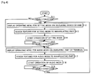
- Fig. 4 is an operation flowchart of the controlling part 12 of this embodiment.
- the controlling part 12 determines whether the HMD 30 is in a visible condition or not by the status signal (Step S11). When it is determined to be in a visible condition (Step S 11, YES), the controlling part 12 displays an operating menu of the setting mode on the displaying device 32 of the HMD 30 (Step S12). At this time, the signal processing part 14 generates an image signal for displaying the operating menu under instruction by the controlling part 12, and gives it to the video-output processing part 20. Details of the operating menu of the setting mode will be described in detail later.
- Step S13 the controlling part 12 assigns features for the setting mode to the manipulating part 13 of the terminal 10 (Step S13). Details of the features for the setting mode will be described later. Accordingly, the terminal 10 turns to the setting mode. In this setting mode, the user operates the manipulating part 13 of the terminal 10, and can set the terminal 10 to a desired reproducing mode (Step S 14).
- the controlling part 12 continues determination of whether the HMD 30 is in a visible condition or not (Step S15). Then, when the HMD 30 migrates from the visible condition to an invisible condition (Step S15, NO), the controlling part 12 displays an operating menu of the audio mode on the displaying part 16 of the terminal 10 (Step S16). At this time, the signal processing part 14 generates an image signal for displaying the operating menu under instruction by the controlling part 12, and gives the signal to the displaying device 16. Details of the operating menu of the audio mode will be described later.
- the controlling part 12 assigns features for the audio mode to the manipulating part 13 of the terminal 10 (Step S17). Details of the features for the audio mode will be described later. Accordingly, the terminal 10 turns to the audio mode. In this audio mode, the user can manipulate the manipulating part 13 of the terminal 10 to reproduce an audio content (Step S18).
- Step S19 the controlling part 12 continues determination of whether the HMD 30 is in a visible condition or not (Step S19). Then, when the HMD 30 migrates from the invisible condition to a visible condition (Step S19, YES), the controlling part 12 returns to Step S12, and makes the terminal 10 migrate to the setting mode.
- the controlling part 12 stops supplying of power to the displaying part 16 of the terminal 10 during a period in which the HMD 30 is in a visible condition (period in which the determinations in Steps S11, S15, S19 are YES). A stop operation of the power supply and so on are as explained in the first embodiment. Also, for saving power consumption, the controlling part 12 stops supplying of power to the displaying device 32 of the HMD 30 during a period in which the HMD 30 is in an invisible condition (period in which determinations in the Steps S11, S15, S19 are NO). An operation to stop supplying of power and so on are as explained in the first embodiment.
- FIG. 5 is a view showing an overview of when the HMD 30 is in a visible condition. Shown on the left side of Fig. 5 is a front view of the terminal 10, and shown on the right side of Fig. 5 is a displaying screen 32A displayed on the displaying device 32 of the HMD 30. On a front face of the terminal 10, together with the displaying part 16, an enter key 13a, an up key 13b, a down key 13c, a left key 13d, a right key 13e are disposed as the manipulating part 13.
- Fig. 5 (a) is an overview just after the HMD 30 migrates from an invisible condition to a visible condition.
- the terminal 10 turns to the setting mode, and hence the operating menu I mode for the setting mode is displayed on the displaying screen 32A of the HMD 30.
- the displaying part 16 of the terminal 10 is turned off.
- the operating menu I mode items of various types of reproducing modes, namely an item of movie mode, an item of audio mode, an item of photo mode are aligned and disposed.
- the direction of disposition is a vertical direction seen from the user.
- a cursor Ic (cursor in a frame shape) which indicates one of the items is also disposed.
- a feature (scrolling feature) to change the object indicated by the cursor lc on the operating menu I mode is assigned.
- a feature to set the terminal 10 to the reproducing mode which is indicated by the cursor lc is assigned.
- Such features of the manipulating part 13 are the features for the setting mode.
- Fig. 5(a) if the user presses the enter key 13a when the object indicated by the cursor lc is the item of the movie mode, the terminal 10 migrates to the movie mode.
- Fig. 5(b) shows an overview just after migrating to the movie mode.
- the operating menu I movie for the movie mode is displayed, and the displaying part 16 of the terminal 10 remains off.
- items of titles (title 1, title 2, title 3, ...) of video contents with audio stored in the memory part 15 are aligned and disposed.
- the direction of disposition is a vertical direction seen from the user.
- the cursor lc which indicates one of the titles is disposed.
- a feature to move the cursor lc vertically is assigned to the up key 13b and the down key 13c of the terminal 10.
- a feature to start reproduction of the title indicated by the cursor lc is assigned to the right key 13e of the terminal 10. Therefore, as shown in Fig. 5(b) for example, if the user presses the right key 13e when the object indicated by the cursor lc is title 1, a video content with audio corresponding to the title 1 is read from the memory part 15, and reproduction thereof is started (a method for reproduction is as already explained in the first embodiment).
- Fig. 5(c) shows an overview of when reproduction of the title 1 is started.
- FIG. 6 is a view showing an overview of when the HMD 30 is in an invisible condition.
- Fig. 6(a) is an overview just after the HMD 30 migrates from a visible condition to an invisible condition.
- the terminal 10 turns to the audio mode, and hence the operating menu I audio for the audio mode is displayed on the displaying part 16 of the terminal 10.
- the displaying screen 32A of the HMD 30 is turned off.
- items of respective titles (title 7, title 8, ...) of audio contents stored in the memory part 15 are aligned and disposed.
- the direction of disposition is a vertical direction seen from the user.
- a cursor lc which indicates one of the titles is also disposed.
- a feature (scrolling feature) to change the object indicated by the cursor lc on the operating menu I audio is assigned.
- a feature to start reproduction of the title indicated by the cursor lc is assigned.
- a feature of rewinding the title is assigned to the left key 13d of the terminal 10.
- Fig. 6(a) for example, if the user presses the right key 13e when the object indicated by the cursor lc is title 7, an audio content corresponding to the title 7 is read from the memory part 15, and reproduction thereof is started (a method for reproduction is as already explained in the first embodiment).
- Fig. 6(b) shows an overview of when reproduction of the title 7 is started.
- the terminal 10 of this embodiment migrates to the setting mode when the HMD 30 migrates from an invisible condition to a visible condition, but when the HMD 30 migrates from a visible condition to an invisible condition inversely, the terminal 10 skips the setting mode and migrates to the audio mode automatically and restricts the features of the manipulating part 13 to only the features regarding reproduction of an audio content. Accordingly, features regarding reproduction of a content including an image, namely, features regarding reproduction of an image content with audio and an image content are eliminated.
- the controlling part 12 displays mode information on the displaying part 16 at least when migrated to the audio mode automatically (refer to Fig. 6(a) ).
- the mode information is character information "audio”. Also, migration to the audio mode may be notified by audio.
- the controlling part 12 of this embodiment creates at least a reproduction history of an audio content, and when the terminal 10 migrates to the audio mode automatically, the controlling part 12 operates based on the reproduction history. For example, the controlling part 12 sets the object indicated by the cursor Ic to a title reproduced recently (in the nearest past) in the operating menu I audio shown in Fig. 6(a) . Thus, when the terminal 10 migrates to the audio mode automatically, the user can just press the right key 13e to reproduce the recently reproduced title immediately.
- the controlling part 12 may set the object indicated by the cursor lc to a title with the largest number of times of reproduction. Alternatively, it may be set to a randomly selected title. Alternatively, it may be set to a randomly selected title weighted by the number of times of reproduction. Also, for example, in the operating menu I audio shown in Fig. 6(a) , the controlling part 12 may set the object indicated by the cursor lc to a title reproduced at the same time zone in a recent date. Such a function of the terminal 10 is useful in the case where the user have a regular activity at a regular time zone everyday (for example, when commuting on a train or a bus).
- the terminal 10 of this embodiment performs the automatic migration of mode according to whether the HMD 30 is in a visible condition or not, but the automatic migration may be performed according to whether the HMD 30 is in an audible condition or not.
- the HMD controlling part 35 determines whether the HMD 30 is in an audible condition or not.
- the HMD 34 generates a signal (status signal) indicating whether the HMD 30 is in an audible condition or not, and transmits the signal to the controlling part 12 of the terminal 10 at a predetermined frequency.
- the controlling part 12 receives the status signal and monitors whether the HMD 30 is in an audible condition or not.
- the controlling part 12 may operate as follows.
- Fig. 7 is an operation flowchart during the movie mode of the controlling part 12 of this embodiment.
- the controlling part 12 acknowledges that a reproduction assignment is inputted according to manipulation contents of the controlling part 13 (Step S21, YES)
- the controlling part 12 instructs the signal processing part 14 to start reproduction of a video content with audio stored in the memory part 15 (Step S22).
- the controlling part 12 monitors whether the HMD 30 is in a visible condition or not (Step S23), and as long as it is in a visible condition (Step S23, YES), the controlling part 12 continues the reproduction. Thereafter, when the HMD 30 migrates from the visible condition to an invisible condition (Step S23, NO), the controlling part 12 instructs the signal processing part 14 to stop the reproduction (Step S24) and also stores the reproduction position at this time (reading position of the memory part 15) (Step S25). Note that this storing may be performed by the signal processing part 14 instead of the controlling part 12. Also, at this time, a reading operation (reproducing operation) of the memory part 15 by the signal processing part 14 is stopped, but power supply to the signal processing part 14 continues.
- Step S26 While the reading operation is stopped, the controlling part 12 monitors whether the HMD 30 is in a visible condition or not (Step S26), and as long as it is in the invisible condition (Step S26, NO), the controlling part 12 continues the stop state. Thereafter, when the HMD 30 migrates from the invisible condition to a visible condition (Step S26, YES), the controlling part 12 instructs the signal processing part 14 to restart the reproduction of the video content with audio at the aforementioned stored reproduction position (Step S27), and returns to Step S23.
- the terminal 10 of this embodiment stops the reproduction automatically. Thereafter, when the HMD 30 migrates from the invisible condition to a visible condition, the terminal 10 restarts the reproduction from the stop position automatically. Therefore, the user of this embodiment can stop reproduction of a content just by retracting the display arm 64 while watching a video content with audio: Thereafter, the user can watch the content again from a stop position just by reeling out the display arm 64.
- the controlling part 12 of this embodiment may display a pause screen (continually display an image that is displayed at the time of stopping).
- the signal processing part 14 continuously sends image information for the pause screen to the video-output processing part 20 under instruction by the controlling part 12. This image information is the same image information which is sent to the video-output processing part 20 at timing of the time of stopping.
- the controlling part 12 of this embodiment sets a reproduction position at the time of restarting to the same as a stored reproduction position, but it may be set to slightly before (a few seconds before) the stored reproduction position. By this setting, a possibility that the user misses a part of a video content with audio is reduced further, and it is possible to make the user recall the connection of the content when restarting. Also, the controlling part 12 of this embodiment restarts reproduction just after the HMD 30 migrates from an invisible condition to a visible condition, but the controlling part 12 may wait just after the migration and thereafter may restart the reproduction at the time when the user inputs an assignment of restarting via the manipulating part 13.
- the controlling part 12 of this embodiment may stop supplying of power to the displaying device 32 of the HMD 30 only during a period in which the HMD 30 is in an invisible condition (Step S23, NO; Step S26, NO), similarly to the first embodiment.
- the operation of the displaying device 32 does not become stable immediately after the HMD 30 migrates from the invisible condition to a visible condition (Step S26, YES), and hence the controlling part 12 may restart the reproduction after waiting for the operation of the displaying device 32 to be stable.
- the controlling part 12 of this embodiment stops reproduction of a video content with audio (Step S24) when the HMD 30 migrates from a visible condition to an invisible condition (Step S23, NO), but the controlling part 12 may only perform storing of a reproduction position (Step S25) while allowing the reproduction of images to continue.
- Step S26 when the HMD 30 migrates to a visible condition (Step S26, YES), the reproduction is performed again from the stored reproduction position.
- the operation flowchart of the controlling part 12 is as shown in Fig. 8 .
- the operation flowchart in Fig. 8 corresponds to one in which Step S24 of Fig. 7 is omitted.
- the controlling function on reproduction position of this embodiment is to control a reproduction position according to whether the HMD 30 is in a visible condition or not during reproduction of a video content with audio, but also controlling functions on reproduction position as follows can be realized.
- this embodiment is a modification example of the third embodiment, but the first embodiment or the second embodiment may be modified similarly.
- Fig. 9 is a diagram showing an electrical structure of the fifth embodiment.
- a main characteristic of this embodiment is that a connection part 79 for connecting a second connectable device is provided in the terminal 10.
- a connectable device to be connected to the connection part 79 is a DVD player 80, a not-shown television tuner, a not-shown digital camera, or the like as shown in Fig. 9 .
- the case that an object to be connected is the DVD player 80 will be explained as a representative.
- the DVD player 80 is connectable to the connection part 79 of the terminal 10 via a connection part 84.
- the DVD player 80 can reproduce various types of disks such as a compact disk storing audio contents, a compact disk storing image contents, a DVD storing video contents with audio, and the like.
- the DVD player 80 is provided with a player flag 82 indicating identification information of the DVD player 80.
- the controlling part 12 of the terminal 10 refers to the player flag 82 via the connection part 79, and acknowledges the type of the connectable device (here the DVD player 80).
- the connection part 79 of the terminal 10 is provided with a mechanical switch or the like, and the controlling part 12 detects presence of a connection of a connectable device or not by an output signal of the mechanical switch.
- a DVD drive part 81 to which a disk can be inserted is mounted.
- a controlling part 83 of the DVD player 80 identifies a disk inserted in the DVD drive part 81 and can also obtain a content list of the disk and determining whether an image is included in contents of the disk or not (note that the image mentioned here includes video as well).
- the controlling part 83 gives the content list of the disk and information indicating presence of an image (image presence information) to the terminal 10 via the connection part 84.
- the DVD drive part 81 reproduces a content stored in the disk and generates a signal of the content, and supplies the signal to the terminal 10 via the connection part 84.
- the content list and the image presence information given to the terminal 10 is acknowledged by the controlling part 12, and the signal of the content given to the terminal 10 is inputted to the signal processing part 14.
- an operation procedure of the controlling part 12 of the terminal 10 will be explained. Note that here it is assumed that the HMD 30 is in a visible condition.
- the controlling part 12 When the controlling part 12 detects that a connectable device is connected to the connection part 79, the controlling part 12 refers to the player flag 82 and acknowledges the type of the connectable device (here the DVD player 80). Then, the controlling part 12 receives the content list and the image presence information from the DVD player 80. However, when no disk is inserted in the DVD drive part 81, these information will not be transmitted from the DVD player 80, and hence the controlling part 12 puts the terminal 10 in a standby state.
- a display destination of the operating menu is the displaying device 32 of the HMD 30 or the displaying part 16 of the terminal 10. Note that a method of displaying the operating menu on the displaying device 32 and a method of displaying the operating menu on the displaying part 16 are as described above. Also, features assigned to the manipulating key 13 are features regarding reproduction of a content stored in the memory part 15.
- the controlling part 12 receives the content list and the image presence information sent from the DVD player 80 and determines whether an image is included in contents of the disk or not based on the image presence information.
- features assigned to the manipulating key 13 are features regarding reproduction of a content stored in the disk.
- the terminal 10 of this embodiment changes contents of the operating menu according to a driving condition (here presence of disk insertion) of a connectable device (here the DVD player 80). Also, the terminal 10 of this embodiment changes a display destination of the operating menu regarding the connectable device (here the DVD player 80) according to the type (here, whether an image is included or not) of a content sent from the connectable device (here the DVD player 80).
- a driving condition here presence of disk insertion
- the terminal 10 of this embodiment changes a display destination of the operating menu regarding the connectable device (here the DVD player 80) according to the type (here, whether an image is included or not) of a content sent from the connectable device (here the DVD player 80).
- the terminal 10 when the terminal 10 performs an operation adapted to the driving condition of the connectable device (here the DVD player 80), operability of the terminal 10 when the connectable device (here the DVD player 80) is connected improves.
- the operation of the controlling part 12 is changed only according to the driving condition of the connectable device with an assumption that the driving condition of the HMD 30 do not change, but the operation of the controlling part 12 may be changed according to both the driving condition of the HMD 30 and the driving condition of the connectable device.
- the connectable device is the DVD player 80, but as long as a signal of a content can be supplied to the terminal 10, it may be another connectable device such as a television tuner, a digital camera, an image storager, or the like.
- the terminal 10 may be allowed to operate according to ON/OFF of the power of the digital camera. The operation of the terminal 10 side at this time is as follows for example.
- the controlling part 12 displays an operating menu regarding the memory part 15 (content list of contents stored in the memory part 15) on the displaying device 32 of the HMD 30 or the displaying part 16 of the terminal 10, and when the power of the digital camera is on, the controlling part 12 displays an image (through image or photographed image) supplied from the digital camera on the displaying device 32 of the HMD 30.
Landscapes
- Engineering & Computer Science (AREA)
- Multimedia (AREA)
- Signal Processing (AREA)
- Controls And Circuits For Display Device (AREA)
- Signal Processing For Digital Recording And Reproducing (AREA)
- Digital Computer Display Output (AREA)
- Control Of Indicators Other Than Cathode Ray Tubes (AREA)
Applications Claiming Priority (3)
| Application Number | Priority Date | Filing Date | Title |
|---|---|---|---|
| JP2005284772 | 2005-09-29 | ||
| JP2006106126 | 2006-04-07 | ||
| PCT/JP2006/318522 WO2007037148A1 (ja) | 2005-09-29 | 2006-09-19 | コンテンツ再生システム |
Publications (3)
| Publication Number | Publication Date |
|---|---|
| EP1930871A1 true EP1930871A1 (de) | 2008-06-11 |
| EP1930871A4 EP1930871A4 (de) | 2016-03-30 |
| EP1930871B1 EP1930871B1 (de) | 2019-11-13 |
Family
ID=37899577
Family Applications (1)
| Application Number | Title | Priority Date | Filing Date |
|---|---|---|---|
| EP06810264.9A Active EP1930871B1 (de) | 2005-09-29 | 2006-09-19 | Inhaltswiedergabesystem |
Country Status (5)
| Country | Link |
|---|---|
| US (1) | US8433173B2 (de) |
| EP (1) | EP1930871B1 (de) |
| JP (1) | JP5272409B2 (de) |
| CN (1) | CN101243485B (de) |
| WO (1) | WO2007037148A1 (de) |
Families Citing this family (4)
| Publication number | Priority date | Publication date | Assignee | Title |
|---|---|---|---|---|
| JP5681850B2 (ja) * | 2010-03-09 | 2015-03-11 | レノボ・イノベーションズ・リミテッド(香港) | ヘッドマウントディスプレイを外部表示装置として使用する携帯端末 |
| WO2017113313A1 (zh) * | 2015-12-31 | 2017-07-06 | 深圳市柔宇科技有限公司 | 头戴式显示设备及头戴式显示系统 |
| KR102452314B1 (ko) | 2016-09-08 | 2022-10-07 | 삼성전자주식회사 | 컨텐츠 재생 방법 및 이를 지원하는 전자 장치 |
| CN113728621A (zh) * | 2019-04-09 | 2021-11-30 | 麦克赛尔株式会社 | 头戴式信息处理装置 |
Family Cites Families (21)
| Publication number | Priority date | Publication date | Assignee | Title |
|---|---|---|---|---|
| JP3144068B2 (ja) * | 1992-06-11 | 2001-03-07 | ソニー株式会社 | オーディオ・ビジュアルシステム |
| JPH0954572A (ja) * | 1995-08-18 | 1997-02-25 | Sony Corp | コンピュータディスプレイ用表示手段における表示領域エリアの有効活用方法と装置 |
| JP3796776B2 (ja) * | 1995-09-28 | 2006-07-12 | ソニー株式会社 | 映像音声再生装置 |
| JPH10133840A (ja) | 1996-11-01 | 1998-05-22 | Olympus Optical Co Ltd | 情報処理用システム装置 |
| JP2000338912A (ja) * | 1999-06-01 | 2000-12-08 | Hitachi Ltd | ディスプレイ装置 |
| JP4350211B2 (ja) * | 1999-06-23 | 2009-10-21 | オリンパス株式会社 | 頭部装着型映像表示装置の制御装置 |
| JP2001238159A (ja) * | 2000-02-23 | 2001-08-31 | Olympus Optical Co Ltd | 携帯型表示システム |
| US7474276B2 (en) * | 2000-06-20 | 2009-01-06 | Olympus Optical Co., Ltd. | Display system and microdisplay apparatus |
| US7123212B2 (en) * | 2000-12-22 | 2006-10-17 | Harman International Industries, Inc. | Information transmission and display method and system for a handheld computing device |
| JP2002350771A (ja) * | 2001-05-25 | 2002-12-04 | Nikon Corp | ヘッドマウントディスプレイ装置 |
| JP2003060571A (ja) * | 2001-08-09 | 2003-02-28 | Seiko Epson Corp | 光送信器 |
| JP2004236242A (ja) * | 2003-01-31 | 2004-08-19 | Nikon Corp | ヘッドマウントディスプレイ |
| US7154493B2 (en) * | 2003-03-13 | 2006-12-26 | Microsoft Corporation | Monitor interconnect compensation by signal calibration |
| WO2005004156A1 (ja) * | 2003-07-01 | 2005-01-13 | Pioneer Corporation | 情報記録媒体、情報記録装置及び方法、情報再生装置及び方法、情報記録再生装置及び方法、記録又は再生制御用のコンピュータプログラム、並びに制御信号を含むデータ構造 |
| JP2005057714A (ja) * | 2003-07-31 | 2005-03-03 | Toshiba Corp | 送信機器及び送信方法 |
| JP2005071147A (ja) * | 2003-08-26 | 2005-03-17 | Casio Comput Co Ltd | グラフ表示制御装置及びプログラム |
| US7487273B2 (en) * | 2003-09-18 | 2009-02-03 | Genesis Microchip Inc. | Data packet based stream transport scheduler wherein transport data link does not include a clock line |
| US7269673B2 (en) * | 2004-02-18 | 2007-09-11 | Silicon Image, Inc. | Cable with circuitry for asserting stored cable data or other information to an external device or user |
| KR100587547B1 (ko) * | 2004-04-07 | 2006-06-08 | 삼성전자주식회사 | 컨텐츠별로 싱크 디바이스로의 출력을 제어하는 소스디바이스 및 그 방법 |
| JP4642400B2 (ja) * | 2004-07-20 | 2011-03-02 | オリンパス株式会社 | 情報表示システム |
| US7548675B2 (en) * | 2004-09-29 | 2009-06-16 | Finisar Corporation | Optical cables for consumer electronics |
-
2006
- 2006-09-19 US US11/921,299 patent/US8433173B2/en active Active
- 2006-09-19 WO PCT/JP2006/318522 patent/WO2007037148A1/ja active Application Filing
- 2006-09-19 EP EP06810264.9A patent/EP1930871B1/de active Active
- 2006-09-19 CN CN2006800294244A patent/CN101243485B/zh not_active Expired - Fee Related
- 2006-09-19 JP JP2007537582A patent/JP5272409B2/ja not_active Expired - Fee Related
Non-Patent Citations (1)
| Title |
|---|
| See references of WO2007037148A1 * |
Also Published As
| Publication number | Publication date |
|---|---|
| EP1930871A4 (de) | 2016-03-30 |
| WO2007037148A1 (ja) | 2007-04-05 |
| EP1930871B1 (de) | 2019-11-13 |
| US8433173B2 (en) | 2013-04-30 |
| JP5272409B2 (ja) | 2013-08-28 |
| US20090048693A1 (en) | 2009-02-19 |
| CN101243485B (zh) | 2011-05-18 |
| JPWO2007037148A1 (ja) | 2009-04-02 |
| CN101243485A (zh) | 2008-08-13 |
Similar Documents
| Publication | Publication Date | Title |
|---|---|---|
| JP4834187B1 (ja) | 再生装置、表示装置、テレビジョン受像機、システム、認識方法、プログラム、及び、記録媒体 | |
| US20080303947A1 (en) | Audio Processing Apparatus and Display Apparatus with Same | |
| US8776120B2 (en) | Remote controller with multimedia content display and control method thereof | |
| JP2002007064A (ja) | 情報記録及びデコーダ機能を備えたコンピュータ用マウス | |
| KR20090036408A (ko) | 영상표시장치 및 그의 edid 정보 제공 방법 | |
| EP1930871B1 (de) | Inhaltswiedergabesystem | |
| KR20160087649A (ko) | 사용자 단말 장치, 시스템 및 그 제어 방법 | |
| CN111405221A (zh) | 显示设备及录制文件列表的显示方法 | |
| JP4504147B2 (ja) | 電子機器 | |
| JP3891168B2 (ja) | 電子機器、コンテンツ転送方法及びそのプログラム | |
| US8253857B2 (en) | Broadcasting receiving apparatus | |
| JP5194794B2 (ja) | 再生装置、ヘッドマウントディスプレイ装置およびその再生装置を実現するプログラム | |
| JP5256738B2 (ja) | コンテンツデータ再生システムおよびそのコンテンツデータ再生システムを実現するプログラム | |
| CN112802440B (zh) | 一种显示设备及声音低延迟处理方法 | |
| JP2009288892A (ja) | ヘッドマウントディスプレイ装置 | |
| KR101639306B1 (ko) | 멀티미디어 컨텐츠 디스플레이를 구비한 원격 제어장치 및 그의 제어 방법 | |
| CN112738576A (zh) | 一种显示设备及声音低延迟处理方法 | |
| JP2023090814A (ja) | 共有情報処理装置及び制御プログラム | |
| CN111641855A (zh) | 一种双屏显示设备及其音频输出方法 | |
| WO2011122683A1 (ja) | 記録装置、記録システム、表示装置、テレビジョン受像機、記録方法、プログラム、および、記録媒体 | |
| KR20100019241A (ko) | 미디어 플레이어를 제어하는 장치 및 방법 | |
| JP2008011317A (ja) | 予約項目表示方法および携帯型テレビ放送受信装置 | |
| JP2006157169A (ja) | 表示制御装置および方法、並びにプログラム | |
| JP2013115723A (ja) | コンテンツ受信システム、装着装置、及び端末装置 | |
| JP2012043484A (ja) | コンテンツ再生装置用クレードル、および、給電方法 |
Legal Events
| Date | Code | Title | Description |
|---|---|---|---|
| PUAI | Public reference made under article 153(3) epc to a published international application that has entered the european phase |
Free format text: ORIGINAL CODE: 0009012 |
|
| 17P | Request for examination filed |
Effective date: 20080103 |
|
| AK | Designated contracting states |
Kind code of ref document: A1 Designated state(s): AT BE BG CH CY CZ DE DK EE ES FI FR GB GR HU IE IS IT LI LT LU LV MC NL PL PT RO SE SI SK TR |
|
| RAP1 | Party data changed (applicant data changed or rights of an application transferred) |
Owner name: NIKON CORPORATION |
|
| DAX | Request for extension of the european patent (deleted) | ||
| RAP1 | Party data changed (applicant data changed or rights of an application transferred) |
Owner name: NIKON CORPORATION |
|
| RIC1 | Information provided on ipc code assigned before grant |
Ipc: H04N 5/76 20060101ALI20151026BHEP Ipc: H04N 5/765 20060101ALI20151026BHEP Ipc: H04N 5/781 20060101ALI20151026BHEP Ipc: H04N 5/64 20060101ALI20151026BHEP Ipc: G09G 5/00 20060101AFI20151026BHEP |
|
| RA4 | Supplementary search report drawn up and despatched (corrected) |
Effective date: 20160225 |
|
| RIC1 | Information provided on ipc code assigned before grant |
Ipc: H04N 5/64 20060101ALI20160219BHEP Ipc: H04N 5/76 20060101ALI20160219BHEP Ipc: H04N 5/781 20060101ALI20160219BHEP Ipc: G09G 5/00 20060101AFI20160219BHEP Ipc: H04N 5/765 20060101ALI20160219BHEP |
|
| STAA | Information on the status of an ep patent application or granted ep patent |
Free format text: STATUS: EXAMINATION IS IN PROGRESS |
|
| 17Q | First examination report despatched |
Effective date: 20180517 |
|
| GRAP | Despatch of communication of intention to grant a patent |
Free format text: ORIGINAL CODE: EPIDOSNIGR1 |
|
| STAA | Information on the status of an ep patent application or granted ep patent |
Free format text: STATUS: GRANT OF PATENT IS INTENDED |
|
| INTG | Intention to grant announced |
Effective date: 20190529 |
|
| GRAS | Grant fee paid |
Free format text: ORIGINAL CODE: EPIDOSNIGR3 |
|
| GRAA | (expected) grant |
Free format text: ORIGINAL CODE: 0009210 |
|
| STAA | Information on the status of an ep patent application or granted ep patent |
Free format text: STATUS: THE PATENT HAS BEEN GRANTED |
|
| AK | Designated contracting states |
Kind code of ref document: B1 Designated state(s): AT BE BG CH CY CZ DE DK EE ES FI FR GB GR HU IE IS IT LI LT LU LV MC NL PL PT RO SE SI SK TR |
|
| REG | Reference to a national code |
Ref country code: GB Ref legal event code: FG4D |
|
| REG | Reference to a national code |
Ref country code: CH Ref legal event code: EP Ref country code: AT Ref legal event code: REF Ref document number: 1202484 Country of ref document: AT Kind code of ref document: T Effective date: 20191115 |
|
| REG | Reference to a national code |
Ref country code: DE Ref legal event code: R096 Ref document number: 602006058821 Country of ref document: DE |
|
| REG | Reference to a national code |
Ref country code: IE Ref legal event code: FG4D |
|
| REG | Reference to a national code |
Ref country code: NL Ref legal event code: MP Effective date: 20191113 |
|
| REG | Reference to a national code |
Ref country code: LT Ref legal event code: MG4D |
|
| PG25 | Lapsed in a contracting state [announced via postgrant information from national office to epo] |
Ref country code: ES Free format text: LAPSE BECAUSE OF FAILURE TO SUBMIT A TRANSLATION OF THE DESCRIPTION OR TO PAY THE FEE WITHIN THE PRESCRIBED TIME-LIMIT Effective date: 20191113 Ref country code: PL Free format text: LAPSE BECAUSE OF FAILURE TO SUBMIT A TRANSLATION OF THE DESCRIPTION OR TO PAY THE FEE WITHIN THE PRESCRIBED TIME-LIMIT Effective date: 20191113 Ref country code: GR Free format text: LAPSE BECAUSE OF FAILURE TO SUBMIT A TRANSLATION OF THE DESCRIPTION OR TO PAY THE FEE WITHIN THE PRESCRIBED TIME-LIMIT Effective date: 20200214 Ref country code: BG Free format text: LAPSE BECAUSE OF FAILURE TO SUBMIT A TRANSLATION OF THE DESCRIPTION OR TO PAY THE FEE WITHIN THE PRESCRIBED TIME-LIMIT Effective date: 20200213 Ref country code: NL Free format text: LAPSE BECAUSE OF FAILURE TO SUBMIT A TRANSLATION OF THE DESCRIPTION OR TO PAY THE FEE WITHIN THE PRESCRIBED TIME-LIMIT Effective date: 20191113 Ref country code: FI Free format text: LAPSE BECAUSE OF FAILURE TO SUBMIT A TRANSLATION OF THE DESCRIPTION OR TO PAY THE FEE WITHIN THE PRESCRIBED TIME-LIMIT Effective date: 20191113 Ref country code: LT Free format text: LAPSE BECAUSE OF FAILURE TO SUBMIT A TRANSLATION OF THE DESCRIPTION OR TO PAY THE FEE WITHIN THE PRESCRIBED TIME-LIMIT Effective date: 20191113 Ref country code: LV Free format text: LAPSE BECAUSE OF FAILURE TO SUBMIT A TRANSLATION OF THE DESCRIPTION OR TO PAY THE FEE WITHIN THE PRESCRIBED TIME-LIMIT Effective date: 20191113 Ref country code: SE Free format text: LAPSE BECAUSE OF FAILURE TO SUBMIT A TRANSLATION OF THE DESCRIPTION OR TO PAY THE FEE WITHIN THE PRESCRIBED TIME-LIMIT Effective date: 20191113 Ref country code: PT Free format text: LAPSE BECAUSE OF FAILURE TO SUBMIT A TRANSLATION OF THE DESCRIPTION OR TO PAY THE FEE WITHIN THE PRESCRIBED TIME-LIMIT Effective date: 20200313 |
|
| PG25 | Lapsed in a contracting state [announced via postgrant information from national office to epo] |
Ref country code: IS Free format text: LAPSE BECAUSE OF FAILURE TO SUBMIT A TRANSLATION OF THE DESCRIPTION OR TO PAY THE FEE WITHIN THE PRESCRIBED TIME-LIMIT Effective date: 20200313 |
|
| PG25 | Lapsed in a contracting state [announced via postgrant information from national office to epo] |
Ref country code: RO Free format text: LAPSE BECAUSE OF FAILURE TO SUBMIT A TRANSLATION OF THE DESCRIPTION OR TO PAY THE FEE WITHIN THE PRESCRIBED TIME-LIMIT Effective date: 20191113 Ref country code: CZ Free format text: LAPSE BECAUSE OF FAILURE TO SUBMIT A TRANSLATION OF THE DESCRIPTION OR TO PAY THE FEE WITHIN THE PRESCRIBED TIME-LIMIT Effective date: 20191113 Ref country code: DK Free format text: LAPSE BECAUSE OF FAILURE TO SUBMIT A TRANSLATION OF THE DESCRIPTION OR TO PAY THE FEE WITHIN THE PRESCRIBED TIME-LIMIT Effective date: 20191113 Ref country code: EE Free format text: LAPSE BECAUSE OF FAILURE TO SUBMIT A TRANSLATION OF THE DESCRIPTION OR TO PAY THE FEE WITHIN THE PRESCRIBED TIME-LIMIT Effective date: 20191113 |
|
| REG | Reference to a national code |
Ref country code: DE Ref legal event code: R097 Ref document number: 602006058821 Country of ref document: DE |
|
| REG | Reference to a national code |
Ref country code: AT Ref legal event code: MK05 Ref document number: 1202484 Country of ref document: AT Kind code of ref document: T Effective date: 20191113 |
|
| PG25 | Lapsed in a contracting state [announced via postgrant information from national office to epo] |
Ref country code: SK Free format text: LAPSE BECAUSE OF FAILURE TO SUBMIT A TRANSLATION OF THE DESCRIPTION OR TO PAY THE FEE WITHIN THE PRESCRIBED TIME-LIMIT Effective date: 20191113 |
|
| PLBE | No opposition filed within time limit |
Free format text: ORIGINAL CODE: 0009261 |
|
| STAA | Information on the status of an ep patent application or granted ep patent |
Free format text: STATUS: NO OPPOSITION FILED WITHIN TIME LIMIT |
|
| 26N | No opposition filed |
Effective date: 20200814 |
|
| PG25 | Lapsed in a contracting state [announced via postgrant information from national office to epo] |
Ref country code: SI Free format text: LAPSE BECAUSE OF FAILURE TO SUBMIT A TRANSLATION OF THE DESCRIPTION OR TO PAY THE FEE WITHIN THE PRESCRIBED TIME-LIMIT Effective date: 20191113 Ref country code: AT Free format text: LAPSE BECAUSE OF FAILURE TO SUBMIT A TRANSLATION OF THE DESCRIPTION OR TO PAY THE FEE WITHIN THE PRESCRIBED TIME-LIMIT Effective date: 20191113 |
|
| PG25 | Lapsed in a contracting state [announced via postgrant information from national office to epo] |
Ref country code: IT Free format text: LAPSE BECAUSE OF FAILURE TO SUBMIT A TRANSLATION OF THE DESCRIPTION OR TO PAY THE FEE WITHIN THE PRESCRIBED TIME-LIMIT Effective date: 20191113 |
|
| REG | Reference to a national code |
Ref country code: DE Ref legal event code: R119 Ref document number: 602006058821 Country of ref document: DE |
|
| PG25 | Lapsed in a contracting state [announced via postgrant information from national office to epo] |
Ref country code: MC Free format text: LAPSE BECAUSE OF FAILURE TO SUBMIT A TRANSLATION OF THE DESCRIPTION OR TO PAY THE FEE WITHIN THE PRESCRIBED TIME-LIMIT Effective date: 20191113 |
|
| REG | Reference to a national code |
Ref country code: CH Ref legal event code: PL |
|
| GBPC | Gb: european patent ceased through non-payment of renewal fee |
Effective date: 20200919 |
|
| REG | Reference to a national code |
Ref country code: BE Ref legal event code: MM Effective date: 20200930 |
|
| PG25 | Lapsed in a contracting state [announced via postgrant information from national office to epo] |
Ref country code: LU Free format text: LAPSE BECAUSE OF NON-PAYMENT OF DUE FEES Effective date: 20200919 |
|
| PG25 | Lapsed in a contracting state [announced via postgrant information from national office to epo] |
Ref country code: DE Free format text: LAPSE BECAUSE OF NON-PAYMENT OF DUE FEES Effective date: 20210401 Ref country code: FR Free format text: LAPSE BECAUSE OF NON-PAYMENT OF DUE FEES Effective date: 20200930 |
|
| PG25 | Lapsed in a contracting state [announced via postgrant information from national office to epo] |
Ref country code: CH Free format text: LAPSE BECAUSE OF NON-PAYMENT OF DUE FEES Effective date: 20200930 Ref country code: BE Free format text: LAPSE BECAUSE OF NON-PAYMENT OF DUE FEES Effective date: 20200930 Ref country code: LI Free format text: LAPSE BECAUSE OF NON-PAYMENT OF DUE FEES Effective date: 20200930 Ref country code: GB Free format text: LAPSE BECAUSE OF NON-PAYMENT OF DUE FEES Effective date: 20200919 Ref country code: IE Free format text: LAPSE BECAUSE OF NON-PAYMENT OF DUE FEES Effective date: 20200919 |
|
| PG25 | Lapsed in a contracting state [announced via postgrant information from national office to epo] |
Ref country code: TR Free format text: LAPSE BECAUSE OF FAILURE TO SUBMIT A TRANSLATION OF THE DESCRIPTION OR TO PAY THE FEE WITHIN THE PRESCRIBED TIME-LIMIT Effective date: 20191113 Ref country code: CY Free format text: LAPSE BECAUSE OF FAILURE TO SUBMIT A TRANSLATION OF THE DESCRIPTION OR TO PAY THE FEE WITHIN THE PRESCRIBED TIME-LIMIT Effective date: 20191113 |