EP1930162B1 - Dispositifs et procédés pour introduire au moins une bande de matière ou une rame dans une plieuse - Google Patents
Dispositifs et procédés pour introduire au moins une bande de matière ou une rame dans une plieuse Download PDFInfo
- Publication number
- EP1930162B1 EP1930162B1 EP07123681A EP07123681A EP1930162B1 EP 1930162 B1 EP1930162 B1 EP 1930162B1 EP 07123681 A EP07123681 A EP 07123681A EP 07123681 A EP07123681 A EP 07123681A EP 1930162 B1 EP1930162 B1 EP 1930162B1
- Authority
- EP
- European Patent Office
- Prior art keywords
- guide rail
- cross
- cutting device
- web
- former
- Prior art date
- Legal status (The legal status is an assumption and is not a legal conclusion. Google has not performed a legal analysis and makes no representation as to the accuracy of the status listed.)
- Not-in-force
Links
Images


Classifications
-
- B—PERFORMING OPERATIONS; TRANSPORTING
- B41—PRINTING; LINING MACHINES; TYPEWRITERS; STAMPS
- B41F—PRINTING MACHINES OR PRESSES
- B41F13/00—Common details of rotary presses or machines
- B41F13/02—Conveying or guiding webs through presses or machines
- B41F13/03—Threading webs into printing machines
-
- B—PERFORMING OPERATIONS; TRANSPORTING
- B65—CONVEYING; PACKING; STORING; HANDLING THIN OR FILAMENTARY MATERIAL
- B65H—HANDLING THIN OR FILAMENTARY MATERIAL, e.g. SHEETS, WEBS, CABLES
- B65H45/00—Folding thin material
- B65H45/12—Folding articles or webs with application of pressure to define or form crease lines
- B65H45/22—Longitudinal folders, i.e. for folding moving sheet material parallel to the direction of movement
- B65H45/221—Longitudinal folders, i.e. for folding moving sheet material parallel to the direction of movement incorporating folding triangles
- B65H45/226—Positional adjustment of folding triangles
-
- B—PERFORMING OPERATIONS; TRANSPORTING
- B65—CONVEYING; PACKING; STORING; HANDLING THIN OR FILAMENTARY MATERIAL
- B65H—HANDLING THIN OR FILAMENTARY MATERIAL, e.g. SHEETS, WEBS, CABLES
- B65H2301/00—Handling processes for sheets or webs
- B65H2301/50—Auxiliary process performed during handling process
- B65H2301/52—Auxiliary process performed during handling process for starting
- B65H2301/522—Threading web into machine
Definitions
- the invention relates to a device and method for drawing at least one material web or of at least one web strand into a folding apparatus according to the preamble of claim 1, 31 or 33.
- a folder such. B. off WO 00/56652 A1 comprises a superstructure, in which merged from one or more printing units paper webs combined, possibly longitudinally cut and placed over each other, at least one former, on each of which in the superstructure of one or more paper webs merged web track is folded longitudinally, and a Cross-cutting device in which the leksgefalzte web is broken down into individual products.
- the cross-cutting device is realized by a rotating knife cylinder, the blades cooperate for cutting the web track with an abutment on a gripper or folding blade.
- the grippers of this cylinder retain the products singulated by the cross-cutter on the surface of the cylinder and convey them to a transfer nip between the folding blade cylinder and a jaw cylinder where a folding blade extends out of the folding blade cylinder to move the product held thereon along a transverse centerline into a jaw to introduce the jaw cylinder and so fold across.
- EP 05 53 740 B1 known to use a holding part in the form of a rail-guided link chain piece to which the obliquely torn off leading end of the recovering web is attached.
- the rail runs next to the intended path of the web through the printing press to the superstructure of a folder.
- the DE 42 10 190 A1 discloses a cutting device with integrated switch, which is arranged between draw rollers and folding cylinders.
- the DE 101 28 821 shows a device for merging paper webs during retraction.
- the US 3 125 335 A discloses a device for drawing webs of material by means of tapes.
- the DE 42 10 190 A1 discloses a cutting device with integrated switch, which is arranged between draw rollers and folding cylinders.
- the EP 0 418 903 A2 describes devices for drawing multiple webs in a web-fed rotary printing press from the roll changers to before the formers by means of belts.
- the EP 1 334 940 A1 discloses a longitudinal folding hopper with a material web feeding device.
- a material web is guided by a first catchment means until shortly before the L Lucassfalztrichter and taken over there by a second, sting-occupied catchment.
- a continuous guide rail from the roll changer to the Leksfalztrichter without transfer is not provided.
- the invention has for its object to provide a device and method for drawing at least one web or at least one web strand in a folder.
- the guide rail guided along the former can guide the web strand at least right up to the cross cutting device; Beyond that aids for automated retraction of the strand are no longer necessary because there is no longer continuous strand, but only individual products.
- the guide rail is preferably twisted at the level of the former, preferably by about 90 °.
- the former is preferably displaceable parallel to the longitudinal axis of the cross cutting device.
- the guide rail of a Adjusting movement of the former is able to follow, a lying in the running direction of the web strand in front of the former hopper section of the guide rail should be stretchable.
- the guide rail should be present between the input of the former and the cross-cutting device, a hinge portion.
- the joint portion can be realized in a simple manner by one or more lateral cuts in the guide rail. This allows in particular a one-piece implementation of the guide rail over the joint section.
- the guide rail has a groove, in particular a longitudinal groove with a bottom and two side walls, in which the holding part is guided, and the cuts cut through each one of the side walls and the bottom, so that the not severed side wall is comparatively easily flexible.
- the guide rail is extended beyond the cross-cutting device, so that a web strand can be pulled through the cross-cutting device with the aid of a holding part guided on the guide rail.
- the cross cutting device must then be in an open position during the drawing of all webs of the web strand, and only when the webs are fully retracted, the cross cutting device can be set in motion to separate white waste forming the leading portion of the web strand.
- a capping device for separating leading white waste from the web strand in front of the cross-cutting device, can be provided, and an input of the Cross-cutting device is arranged in extension of the passage direction of the web strand through the capping device, so that after the separation of the white waste the usable part of the web strand enters the cross cutting device without requiring a guide through the guide rail.
- its entrance is preferably located vertically below the cap means so that the tip (beginning of the web) of the useful part of the web strand is guided by gravity into the entrance of the cross cutter.
- the guide rail preferably has a bend between the capping device and the input of the cross-cutting device and runs past the entrance of the cross-cutting device.
- An arranged in extension of the guide rail beyond the former hopper memory for receiving holding parts allows it to retract shortly after a pull several material webs, without that in the meantime the holding part of a web would have to be moved back to its starting point to the guide rail for the holding part of another material web vacate.
- the memory can be particularly space-saving formed by a spiral or helical rail piece, which is able to a holding part or to receive several holding parts in succession.
- the storage device is preceded by a separating device for separating the holding parts from their respective material webs, so that the leading sections of the material webs entrained by the holding parts do not have to be accommodated in the store as well.
- the separator is conveniently located on the guide rail between the bend and the store.
- the guide rail can extend continuously from a reel changer of a printing unit upstream of the folder into the folder.
- the superstructure of the folding apparatus preferably has several ways, on each of which at least one material web can be guided through the superstructure and to the cross cutting device, and a plurality of rail pieces running along each of these paths unite in front of the Cross cutting device with the guide rail.
- a turnout is preferably arranged at the joining points of the rail pieces.
- an adhesive preparation device is preferably arranged upstream of a connection point, which serves to make a web strand passing through it locally tacky, so that it adheres to a second, already drawn-in web strand.
- the adhesive preparation device may be an adhesive tape dispenser for a double-sided adhesive tape or a glue dispenser.
- the adhesive preparation device In order to actuate the adhesive preparation device in time, it is preferably associated with a sensor for detecting a web start that passes it.
- the entry of the material webs is synchronized with each other so that the second material web is only guided to the junction when the holding part of the first material web has passed this point and thus does not hinder the movement of the holding part of the second material web.
- retraction in which first a first material web is guided on the guide rail to a point at which one of the rail pieces united with the guide rail, and if the holding part of the first material web has passed this point, a second material web on the rail section is guided to this point and from there on the guide rail to the cross cutting device.
- the material webs can be passed through the cross-cutting device, in which case the cross-cutting device expediently remains at rest until all material webs have been pulled through, so that no holding part is damaged by the cross-cutting device.
- the webs of material can pass through a capping device upstream of the cross-cutting device and initially past the cross-cutting device with the aid of the guide rail, and only when the tips of all the material webs held on the holding parts have passed the capping device is it actuated to feed the strand of material webs caps and the leading end resulting from caps entering the cross cutting device.
- the cross-cutting device If, during the drawing in, the cross-cutting device is already moved in the right direction, it can correctly separate it into products from the moment when the web strand begins to enter the cross-cutting device.
- a pair of draw rollers of the printing machine or folder is preferably turned off during the drawing of a web, but as soon as the passage of the leader End of the web or of the web strand is detected by the Buchwalzencru, employed and so controlled driven that a tension exerted by the Switzerlandwalzencru approaching a setpoint for continuous printing operation target value.
- Fig. 1 shows a schematic side view of a folding apparatus according to the present invention.
- One of a printing unit, not shown, web 01, z. B. web 01 passes through a chill roll stand 02 and reaches a superstructure 03 of the folder.
- the superstructure 03 comprises a longitudinal cutter 04 for disassembling the incoming paper web 01 into a plurality of juxtaposed partial webs, a turning deck 06, in which the partial webs of the paper web 01 and possibly further, unillustrated, paper webs rearranged, transversely to the direction (from left to right in of the Fig. 1 ) and / or turned and then superimposed. From the turning table 06, the path of the paper web 01 extends over an arrangement of compensating rollers 07 for web length compensation and traction control to a former 08.
- Forming hopper 08 and compensating rollers 07 are in a common frame in the lateral direction of Fig. 1 traced and are to clarify this fact in the Fig. 1 shown twice, in staggered positions.
- the paper web 01 runs downwards through a cross-cutting device 24 and a transverse folding device of per se known, not to be explained more precisely at this point structure.
- a guide rail 09 extends in the Fig. 1 represented as a thick black line.
- the guide rail 09 is shown from its entry into the chill roll stand 02 and to the lower end of the former 08; Preferably, it extends without interruption from the paster of a folder upstream of the folder, in the Fig. 1 not shown printing unit to the former 08 or beyond.
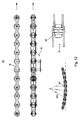
- the guide rail 09 has a U-shaped or, as in Fig. 2 shown, or C-shaped cross-section, in whose groove 23, in particular longitudinal groove 23 each have a chain piece 51 is guided.
- the chain piece 51 is constructed of alternating one- or two-segmented members 52; 53, of which at least one carries out of the groove 23 extending arm 19.
- Two adjacent links 53 common carry an arm 19.
- Chain piece 51 and arm 19 are hereinafter also referred to as holding part 51, 19.
- a hook at the end of the arm 19 is provided to fasten, with the aid of a loop wrapped around it, the leading end 54 of a paper web 01 to be newly collected or a draw-in tip connected to the leading end 54.
- the single-segment members 52 are elastic in itself, z. B. by being made in one piece of an elastic material, or by a (in the Fig. 2 not shown) elastic center piece of spring steel or the like, and thus allow a twisting of the chain piece 51 about an axis parallel to the longitudinal direction of the guide rail 09 axis and a bend of the chain piece 51 about an axis perpendicular to the plane of the paper web 01 axis.
- each motors (not shown) are mounted at regular intervals, each carrying a sprocket, which through a gap in the side of the guide rail 09 in the groove 23 and possibly between the members 52, 53 at the location of the sprocket located chain piece 51 engages.
- the length of the chain piece 51 is chosen slightly larger than the distance between two successive sprockets along the guide rail 09, so that it is ensured that when the chain piece 51 is conveyed along the guide rail 09, always at least one sprocket with the chain piece 51 is engaged and this drives.
- it is sufficient to retract a paper web 01, the leading end 54 to each of the groove 23 projecting arm 19 of a chain piece 51 to fix and then move the chain piece 51 along the guide rail 09 in motion to the Feed in paper web 01.
- Fig. 3 shows in an enlarged view in the same perspective as Fig. 1 the former 08 and its surroundings.
- the course of the guide rail 09 or one of its retracted paper web 01 is in Fig. 3 drawn as a dotted line.
- a merge roll 11 two more rail pieces 12 meet; 13, shown as a dotted or evenly dashed line, with the guide rail 09 together.
- a sensor 14, z. B. a photocell 14 for detecting the presence of a retracted paper web 01 and a Klebvorpungs noticed 16 for applying adhesive 15.
- the adhesive preparation device 16 may be designed to apply a strip of liquid adhesive on the leading portion of a paper web 01 along the rail piece 12 and 13 is passed by her; a possible structure of such a device is z. In EP 04 77 769 B1 described.
- the adhesive preparation device 16 would also be an adhesive tape dispenser which, as soon as the photocell 14 indicates the arrival of a paper web 01, is displaced in the width direction of the paper web 01 in order to unroll a strip of double-sided adhesive tape.
- the adhesive preparation device 16 may also consist of a plurality of adhesive spray nozzles, which are distributed across the width of the paper web 01 and each of which a photocell 14 is assigned to each at the moment when the leading edge of a paper web 01 passes one of the adhesive nozzles, this to cause an adhesive dose to be sprayed onto the paper web 01. This is in particular in the area lying above the former 08 of Fig. 5 to recognize.
- the point in time at which the paper web 01 guided along the rail section 12 strikes the combining roller 11 is selected such that at this point in time a chain piece 51, that has already fed along the guide rail 09, 13 running paper web 01, the unification roller 11 has passed, so that the coming of the rail section 12 chain piece 51 switch to the guide rail 09 and can be further promoted on this.
- the web strand thus obtained passes through a separating device 17, z. B. a hopper-separating device 17 with a rotating knife and an abutment roller, which serves on all passing paper webs, the tip of which is already adhered to a paper web 01 retracted further than itself, d. H. in particular via the rail pieces 12; 13 supplied paper webs, the no longer needed at this point connection between the arm 19 and the top of the paper web to separate.
- the web strand is deflected again and reaches the sloping downwardly tapered surface of the former. 08 While the web strand is pulled over the side edges of the former 08, its orientation changes; from one to the level of Fig. 3 In a substantially vertical orientation upstream of the hopper inlet roller 18 is a to the plane of the Fig. 3 essentially parallel orientation.
- the guide rail 09 is twisted by 90 ° in a section 21 following the funnel inlet roller 18, for the sake of better depiction being shortened in the longitudinal direction of the guide rail 09 Fig. 4 is shown.
- a piece of the hopper inlet roller 18 and the former 08 are shown; the axis of the hopper inlet roller 18 is parallel to the plane of Fig. 4 aligned.
- the groove 23 turns in the perspective of FIG Fig. 4 gradually forward, and bolts 22 and links 52; 53 of the trapped in the groove 23 chain are visible.
- the orientation of the chain piece 51 is rotated by 90 ° and the arm 19 supported by it is transverse to the plane of FIG Fig.
- the further course of the guide rail 09 is better on the basis of Fig. 5 to recognize the same structure as Fig. 3 from a 90 ° perspective.
- the guide rail 09 extends vertically downwards between conveyor rollers which are offset from each other during web feeding so as not to interfere with the passage of an arm 19 supporting a web tip.
- the guide rail 09 is guided past the cutting gap of a cross-cutting device 24 so that the paper webs 01 are introduced into the cutting gap of this cross-cutting device 24.
- the cross-cutting device 24 comprises a cylinder 26, z. B. knife cylinder 26 and a cylinder 27, z. B.
- gripper cylinder 27 and / or folding blade 27, are arranged on the abutment, not shown, hard rubber, which cooperate with the knives of the knife cylinder 26 when the cross-cutting device 24 is in operation.
- the cylinder 27 is preferably designed as a folding blade cylinder 27 and has holding elements, for. As grippers or punctures.
- During the retraction of the paper webs 01 are the cylinder 26; 27 of the transverse cutting device 24 in the illustrated position with knives 28 of the knife cylinder 26 aligned substantially on a line parallel to the guide rail 09, so that between the Cylinders 26; 27 is a gap open through which the paper webs 01 can be pulled.
- FIG. 12 An advantageous embodiment of the chain 51 is in Fig. 12 shown.
- the chain 51 has respective rollers mounted on bolts 22, wherein the bolts 22 are connected by means of tabs.
- the chain 51 can not only perform a pivoting movement about the longitudinal axes of the bolt 22, z.
- the holes in the tabs slightly larger than the diameter of the pin 22, so that the chain 51 is transversely to the running direction or in the longitudinal axis direction of the bolt 22 curvable. In the curved state, this results in a maximum radius of curvature R51 of 1000 mm or, preferably, less than 600 mm, particularly preferably less than 500 mm.
- the bolt 22 in its longitudinal direction with different diameters, in particular crowned execute.
- the front seam separating device 30 serves to separate the rail pieces 32; 33 supplied web strands of their holding parts; the rear separates the first fed Paper web 01, which forms the tip of the web strand entering the cross cutting device 24, from its holding part.
- the crosscutting device 24 can be set in motion. With the first cut, the tips of all paper webs 01 of the drawn-through web strand are separated.
- Fig. 6 shows in one too Fig. 4 analog perspective, an embodiment of the folder with two juxtaposed formers 08 for processing four-page wide paper webs 01.
- each of the former 08 is assigned its own guide rail 09 for guiding paper webs 01 by the cross-cutting device 24.
- the two guide rails 09 are united before passing through the cross-cutting device 24;
- An advantage of the parallel guided guide rails 09 is that in each case two holding parts can pass through the cross cutting device 24 simultaneously, so that the retraction of the paper webs 01 takes less time, and that the total amount of paper that must be pulled until the holding parts of all paper webs 01 the cross cutting device 24 has happened, is significantly reduced.
- Fig. 7 and 11 show alternative embodiments of the course of the guide rail 09 at the entrance of the cross cutting device 24.
- the input of the cross cutting device 24 is preceded by a capping device 36 for capping the pulled-through web strand.
- the guide rail 09 has a curved portion 37 and extends above a baffle 38 in the lateral direction to a separating device 39, in this case the head portion of each she dissolves the paper web 01 of her holding part.
- the track strand which has become unguided on the other side of the separating device 39 falls freely and is ejected from the folding apparatus; the holding member is further conveyed into one or more stores 41, shown here as a spirally wound guide rail.
- An alternative space-saving design of the memory 41 is a helically curved guide rail, preferably with respect to the axes of the cylinder 26; 27 parallel longitudinal axis.
- the cylinder 26; 27 of the cross-cutting device 24 already phase-synchronous with draw rollers of the folder or upstream parts of the printing press rotate before all the paper webs 01 are finished retracted.
- the capping device 36 once severed the web strand.
- a switch 42 arranged in the input gusset of the cross-cutting device 24 transitions from its position shown in solid lines to the dashed line in order to securely insert the newly formed leading edge of the web strand into the cross-cutting device 24. Since this can already run at the time of capping the web strand with a rotational speed adapted to its conveying speed, the time required to reach stationary printing conditions and thus the amount of waste generated when the printing press starts up are shortened.
- pairs of draw rolls which have a paper web 01 on the way from the roll changer to the cross-cutting device 24, can be used passes, and which are turned off during retraction of the paper web 01, sensors such as the photocells 14 are provided for detecting the presence of the paper web 01, which, as soon as they detect the passage of a paper web 01 through the Switzerlandwalzencru, cause the draw rollers hired each other and are driven to produce a predetermined tension on the respective paper web 01.
- FIGS. 9 and 10 A preferred embodiment of such a flexible guide rail 09 is based on the FIGS. 9 and 10 explained. It shows the Fig. 9 a plan view of a flexible portion 44 or 46 and Fig. 10 a section through the guide rail of Fig. 9 at the height of the line X - X of the Fig. 9 ,
- the cutting plane is laid by one of a plurality of cuts 47, which are formed in the flexible region 44 and 46 to a plurality of alternately from different sides of the guide rail 09, and respectively cut through the side walls 48 thereof.
- Each remaining in the amount of cuts 47 remaining side wall 48 is much easier flexible than the non-cut guide rail 09, and above all, it allows a controlled bending of the guide rail 09 in a plane without simultaneous twisting.
- the cuts 47 are alternately narrowed or widened depending on the orientation.
- the width of the cuts 47 and the amount of bending are exaggerated; in practice, the width of the cuts 47 and their deformation must not be so strong that the smooth passage of the chain links is endangered by the groove 23 thereby. This requirement is, however, to meet without difficulty, since the required bending freedom of the guide rail 09 is not more than a few degrees and the expansion of the individual cuts 47 in a bend, of course, the smaller the number is.
- a distance X of the guide rail 09 from the paper web 01 is also sufficient for the insertion process for the entire folding structure. ie at least from the unfolded paper web 01 promoting hopper folding roller 18 over the path of the former 08 away to the top.
- the drawing-in process preferably takes place through the printing units associated with the web path while they are not printing.
Landscapes
- Engineering & Computer Science (AREA)
- Mechanical Engineering (AREA)
- Folding Of Thin Sheet-Like Materials, Special Discharging Devices, And Others (AREA)
- Replacement Of Web Rolls (AREA)
- Auxiliary Devices For And Details Of Packaging Control (AREA)
Claims (36)
- Système pour l'introduction d'au moins une bande de matière (01) et/ou d'au moins un ruban constitué de plusieurs bandes de matière dans une plieuse avec une superstructure (03), au moins un cône plieur (08), un dispositif de coupe transversale (24) pour la séparation en produits individuels de la bande de matière (01) transportée dans la superstructure (03) et pliée sur le cône plieur (08), et au moins une glissière de guidage (09), sur laquelle une pièce de maintien (51, 19), où peut être fixée une extrémité (54) de guidage d'au moins une bande de matière (01), est déplacée sur un trajet de ladite bande de matière (01) au travers de la superstructure (03), caractérisé en ce que plusieurs pièces de glissière de guidage (09 ; 12 ; 13 ; 32 ; 33) sont disposées, en ce que ces pièces de glissière de guidage (09 ; 12 ; 13 ; 32 ; 33) se réunissent à la glissière de guidage (09) devant le dispositif de coupe transversale (24) et après au moins un cône plieur (08).
- Système selon la revendication 1, caractérisé en ce que la glissière de guidage (09) est vrillée à la hauteur du cône plieur (08).
- Système selon la revendication 1, caractérisé en ce que le cône plieur (08) est déplaçable dans la direction de coupe du dispositif de coupe transversale (24).
- Système selon la revendication 1, caractérisé en ce que la glissière de guidage (09) présente devant le cône plieur (08) une partie (43) extensible dans la direction de défilement de la bande de matière (01).
- Système selon la revendication 1, caractérisé en ce que la glissière de guidage (09) présente une partie articulée (44 ; 46) entre l'entrée du cône plieur (08) et le dispositif de coupe transversale (24).
- Système selon la revendication 5, caractérisé en ce que la partie articulée (44 ; 46) est obtenue par un ou plusieurs entailles (47) dans la glissière de guidage (09).
- Système selon la revendication 1, caractérisé en ce qu'un espacement (X) de la glissière de guidage (09) par rapport à la bande de papier (01) est sensiblement constant, d'un rouleau d'entrée (18) de cône au-dessus du cône plieur (08) jusqu'au sommet de celui-ci.
- Système selon la revendication 6, caractérisé en ce que la glissière de guidage (09) présente une gorge (23) avec un fond (49) et deux parois latérales (48), dans laquelle la pièce de maintien (19, 51) est guidée, et en ce que les entailles (47) traversent au moins une des parois latérales (48).
- Système selon la revendication 1, caractérisé en ce que la glissière de guidage (09) va jusqu'au-delà du dispositif de coupe transversale (24).
- Système selon l'une des revendications 1 à 9, caractérisé en ce qu'un dispositif coupe-papier (36) est prévu devant le dispositif de coupe transversale (24) pour le détachement du papier de rebut en amorce des bandes de matière (01).
- Système selon la revendication 10, caractérisé en ce qu'une entrée du dispositif de coupe transversale (24) est disposée dans le prolongement de la direction de passage des bandes de matière (01) au travers du dispositif coupe-papier (36).
- Système selon la revendication 10 ou la revendication 11, caractérisé en ce que la glissière de guidage (09) présente une partie incurvée (37) entre le dispositif coupe-papier (36) et l'entrée du dispositif de coupe transversale (24) et s'étend en passant à côté de l'entrée du dispositif de coupe transversale (24).
- Système selon l'une des revendications précédentes, caractérisé en ce qu'un magasin (41) pour la réception de pièces de maintien (19, 51) est disposé le prolongement de la ou des glissières de guidage (09) au-delà du cône plieur (08).
- Système selon la revendication 13, caractérisé en ce que le magasin (41) est constitué par une pièce de glissière en forme de spirale ou d'hélice.
- Système selon la revendication 13 ou la revendication 14, caractérisé en ce qu'un dispositif de détachement (17 ; 30 ; 39) pour le détachement des pièces de maintien (19, 51) de leurs bandes de matière (01) respectives est monté en amont du magasin (41).
- Système selon les revendications 12 et 15, caractérisé en ce que le dispositif de détachement (39) est disposé contre la glissière de guidage (09) entre la partie incurvée (37) et le magasin (41).
- Système selon l'une des revendications précédentes, caractérisé en ce que la glissière de guidage (09) s'étend de manière continue depuis un changeur de bobine d'un groupe d'impression en amont de la plieuse jusqu'à la plieuse.
- Système selon l'une des revendications précédentes, caractérisé en ce que ledit système présente plusieurs trajets, sur chacun desquels un ruban de bande peut être guidé au travers de la superstructure (03) et vers le dispositif de coupe transversale (24).
- Système selon la revendication 18, caractérisé en ce que plusieurs pièces de glissière (09 ; 12 ; 13 ; 32 ; 33) qui s'étendent le long de chacun desdits trajets, se réunissent à la glissière de guidage (09) devant le dispositif de coupe transversale (24).
- Système selon la revendication 19, caractérisé en ce que plusieurs pièces de glissière (12 ; 13 ; 32 ; 33) qui s'étendent le long de chacun desdits trajets, se réunissent à la glissière de guidage (09) après au moins un cône plieur (08).
- Système selon la revendication 20, caractérisé en ce qu'une aiguille (34) est disposée sur chaque point de jonction (29 ; 31) des pièces de glissière (12 ; 13 ; 32 ; 33).
- Système selon la revendication 1, caractérisé en ce que la pièce de maintien (51, 19) comprend une chaîne à bout libre.
- Système selon la revendication 22, caractérisé en ce que la chaîne peut être incurvée transversalement à la direction de transport.
- Système selon la revendication 23, caractérisé en ce que la chaîne comporte des galets avec des axes longitudinaux, et en ce que les prolongements virtuels des axes longitudinaux à l'état incurvé se croisent en un point tel que la chaîne présente un rayon de courbure (R51) inférieur à 1000 mm.
- Système selon la revendication 24, caractérisé en ce que le rayon de courbure (R51) est inférieur à 600 mm.
- Système selon la revendication 1, caractérisé en ce que plusieurs cônes plieurs (08) sont prévus, et en ce qu'une glissière de guidage (09) s'étend le long de chaque cône plieur (08).
- Système selon la revendication 26, caractérisé en ce qu'au moins deux cônes plieurs (08) sont disposés côte à côte, et en ce qu'une glissière de guidage (09) est disposée le long du côté droit du premier cône plieur (08), et une glissière de guidage (09) le long du côté gauche de l'autre cône plieur (08).
- Système selon la revendication 27, caractérisé en ce que des glissières de guidage (09) sont disposées seulement sur les deux côtés des cônes plieurs (08) qui sont distants l'un de l'autre, et non pas sur les côtés proches.
- Système selon la revendication 17, caractérisé en ce qu'au moins deux changeurs de bobine sont prévus et en ce qu'une glissière de guidage (09) s'étend depuis chaque changeur de bobine jusqu'à la plieuse (08).
- Système selon la revendication 1, caractérisé en ce que la glissière de guidage (09) est espacée du cône plieur (08).
- Procédé pour l'introduction d'au moins une bande de matière (01) et/ou d'au moins un ruban constitué de plusieurs bandes de matière dans une plieuse avec une superstructure (03), au moins un cône plieur (08), un dispositif de coupe transversale (24) pour la séparation en produits individuels de la bande de matière (01) transportée dans la superstructure (03) et pliée sur le cône plieur (08), et une glissière de guidage (09), sur laquelle une pièce de maintien (51, 19), où peut être fixée une extrémité (54) de guidage d'au moins une bande de matière (01), est déplacée sur un trajet de ladite bande de matière (01) au travers de la superstructure (03), comportant les caractéristiques suivantes:- une première bande de matière (01) est guidée sur la glissière de guidage (09) vers un point de jonction (29 ; 31) où une des pièces de glissière (12; 13 ; 32 ; 33) se réunit à la glissière de guidage (09),- une deuxième bande de matière est guidée sur la pièce de glissière (12 ; 13 ; 32 ; 33) vers le point de jonction (29 ; 31) et fixée sur la première bande de matière (01), et- les bandes de matière (01) fixées l'une à l'autre continuent à être guidées sur la glissière de guidage (09) et sont introduites dans le dispositif de coupe transversale (24).
- Procédé selon la revendication 31, où la deuxième bande de matière n'est guidée vers le point de jonction (29 ; 31) que lorsque la pièce de maintien (19, 51) de la première bande de matière (01) a dépassé le point de jonction (29 ; 31).
- Procédé selon la revendication 31 ou la revendication 32, où les bandes de matière (01) sur la glissière de guidage (09) sont guidées au travers du dispositif de coupe transversale (24).
- Procédé selon l'une des revendications 31 à 33, caractérisé en ce que- les bandes de matière (01) sont guidées au travers d'un dispositif coupe-papier (36) en amont du dispositif de coupe transversale (24) et sont d'abord passées à côté du dispositif de coupe transversale (24) au moyen de la glissière de guidage (09),- lorsque les extrémités (54) de toutes les bandes de matière (01) ont dépassé le dispositif coupe-papier (36), ce dernier est actionné pour écourter les bandes de matière (01), et- l'extrémité (54) de guidage obtenue par écourtement entre dans le dispositif de coupe transversale (24).
- Procédé selon la revendication 34, où pendant l'introduction, le dispositif de coupe transversale (24) est déplacé conjointement en conformité de phase.
- Procédé selon l'une des revendications 31 à 35, où les pièces de maintien (19, 51) de toutes les bandes de matière (01) sont d'abord recueillies dans un magasin (41) raccordé à la glissière de guidage (09), et sont à l'issue de l'impression reconduites en sens inverse le long de la glissière de guidage (09) vers une position initiale correspondante.
Applications Claiming Priority (3)
| Application Number | Priority Date | Filing Date | Title |
|---|---|---|---|
| DE102004015479 | 2004-03-26 | ||
| DE102004033036A DE102004033036A1 (de) | 2004-03-26 | 2004-07-07 | Falzapparat mit einem Oberbau und Verfahren zum Einziehen von Bahnsträngen bzw. einer Materialbahn in einen Falzapparat |
| EP05717072A EP1727675B1 (fr) | 2004-03-26 | 2005-03-16 | Dispositif pour introduire au moins une bande de matiere ou une rame dans une plieuse |
Related Parent Applications (2)
| Application Number | Title | Priority Date | Filing Date |
|---|---|---|---|
| EP05717072.2 Division | 2005-03-16 | ||
| EP05717072A Division EP1727675B1 (fr) | 2004-03-26 | 2005-03-16 | Dispositif pour introduire au moins une bande de matiere ou une rame dans une plieuse |
Publications (3)
| Publication Number | Publication Date |
|---|---|
| EP1930162A2 EP1930162A2 (fr) | 2008-06-11 |
| EP1930162A3 EP1930162A3 (fr) | 2011-02-16 |
| EP1930162B1 true EP1930162B1 (fr) | 2012-11-28 |
Family
ID=34961374
Family Applications (2)
| Application Number | Title | Priority Date | Filing Date |
|---|---|---|---|
| EP05717072A Not-in-force EP1727675B1 (fr) | 2004-03-26 | 2005-03-16 | Dispositif pour introduire au moins une bande de matiere ou une rame dans une plieuse |
| EP07123681A Not-in-force EP1930162B1 (fr) | 2004-03-26 | 2005-03-16 | Dispositifs et procédés pour introduire au moins une bande de matière ou une rame dans une plieuse |
Family Applications Before (1)
| Application Number | Title | Priority Date | Filing Date |
|---|---|---|---|
| EP05717072A Not-in-force EP1727675B1 (fr) | 2004-03-26 | 2005-03-16 | Dispositif pour introduire au moins une bande de matiere ou une rame dans une plieuse |
Country Status (7)
| Country | Link |
|---|---|
| US (1) | US7387601B2 (fr) |
| EP (2) | EP1727675B1 (fr) |
| JP (1) | JP4523638B2 (fr) |
| AT (1) | ATE405418T1 (fr) |
| DE (2) | DE102004033036A1 (fr) |
| ES (1) | ES2309729T3 (fr) |
| WO (1) | WO2005092614A2 (fr) |
Families Citing this family (11)
| Publication number | Priority date | Publication date | Assignee | Title |
|---|---|---|---|---|
| DE502004006043D1 (de) * | 2003-04-23 | 2008-03-13 | Koenig & Bauer Ag | Rollenrotationsdruckmaschine |
| DE10326080A1 (de) * | 2003-06-10 | 2005-01-27 | OCé PRINTING SYSTEMS GMBH | Druckstraße mit Bahnspeichereinheit und Nachverarbeitungssystem |
| DE102004022541B4 (de) * | 2004-05-05 | 2013-12-05 | Manroland Web Systems Gmbh | Vorrichtung zum Einziehen von Materialbahnen in Aggregate von Rotationsdruckmaschinen |
| DE102005045041B3 (de) | 2005-09-21 | 2007-02-01 | Koenig & Bauer Ag | Vorrichtung und ein Verfahren zur Verwendung einer Vorrichtung zum Einziehen mindestens einer Materialbahn bzw. mindestens eines Bahnstrangs in einen Falzapparat |
| DE102007002875B4 (de) * | 2007-01-15 | 2019-10-10 | Manroland Goss Web Systems Gmbh | Einziehvorrichtung zum Einziehen einer Bedruckstoffbahn in eine Druckmaschine |
| DE102007006064B3 (de) * | 2007-02-07 | 2008-04-10 | Koenig & Bauer Aktiengesellschaft | Befestigungsvorrichtung |
| DE102008001810B4 (de) * | 2008-05-15 | 2014-06-05 | Koenig & Bauer Aktiengesellschaft | Einziehvorrichtung zum Einzug einer Materialbahn in eine Rotationsdruckmaschine |
| US8398063B2 (en) * | 2008-12-10 | 2013-03-19 | Gross International Americas, Inc. | Ribbon transport apparatus and method |
| DE102010001146B4 (de) * | 2010-01-22 | 2015-01-15 | Koenig & Bauer Aktiengesellschaft | Kettenschiene für Einziehketten und ein Verfahren zur Herstellung einer Kettenschiene |
| DE102010042508B4 (de) | 2010-10-15 | 2020-05-07 | Koenig & Bauer Ag | Anordnung, aufweisend eine Rollen-Rotations-Druckmaschine und einen zumindest teilweise darin angeordneten Bedruckstoff und ein Verfahren zum Einziehen zumindest eines vorlaufenden Endes eines Bedruckstoffs mittels zumindest einer Einziehvorrichtung in eine Rollen-Rotations-Druckmaschine |
| EP2676750B1 (fr) * | 2012-06-19 | 2019-10-09 | Georg Fischer Wavin AG | Dispositif de guidage d'appareils à écorcer |
Family Cites Families (18)
| Publication number | Priority date | Publication date | Assignee | Title |
|---|---|---|---|---|
| US3125335A (en) * | 1964-03-17 | Webbing system using preprinted tape | ||
| DE1611283C2 (de) | 1967-08-09 | 1975-11-27 | Koenig & Bauer Ag, 8700 Wuerzburg | Schneid- und Falzapparat an Rollenrotationsmaschinen |
| DE3725634A1 (de) * | 1987-08-03 | 1989-02-16 | Roland Man Druckmasch | Rollenkette fuer eine papierbahneinzugsvorrichtung einer druckmaschine |
| JPH0688695B2 (ja) * | 1989-11-21 | 1994-11-09 | 株式会社東京機械製作所 | 輪転機の紙通し装置 |
| JPH0759453B2 (ja) * | 1989-09-20 | 1995-06-28 | 株式会社東京機械製作所 | 輪転機の紙通し装置 |
| CA2025552C (fr) * | 1989-09-20 | 1993-12-21 | Kunio Suzuki | Dispositif d'engagement d'une bande de papier continu dans une rotative |
| JPH0745325Y2 (ja) * | 1990-06-12 | 1995-10-18 | 株式会社小森コーポレーション | 折機用ウエブ切断装置 |
| DE4129404C2 (de) * | 1990-09-25 | 1993-12-09 | Frankenthal Ag Albert | Querleim-Vorrichtung zum Aufbringen von Leim auf eine bewegte Materialbahn |
| DE4202713C2 (de) * | 1992-01-31 | 1993-11-04 | Koenig & Bauer Ag | Fuehrung zum einziehen einer materialbahn in eine rollenrotationsdruckmaschine |
| DE4210190A1 (de) * | 1992-03-28 | 1993-09-30 | Roland Man Druckmasch | Sicherheitsvorrichtung für laufende Bahnen |
| DE4322929C1 (de) * | 1993-07-09 | 1995-02-16 | Koenig & Bauer Ag | Rollenkette |
| DE4435429C2 (de) * | 1994-10-04 | 2000-07-06 | Wifag Maschf | Rollenrotationsdruckmaschine |
| JP2921605B2 (ja) * | 1995-11-08 | 1999-07-19 | ケーニツヒ ウント バウエル−アルバート アクチエンゲゼルシヤフト | 折丁を製作するための装置 |
| DE19758468A1 (de) | 1997-05-02 | 1998-11-12 | Koenig & Bauer Albert Ag | Längenvariables Führungsschienenstück |
| DE50007814D1 (de) * | 1999-03-19 | 2004-10-21 | Koenig & Bauer Ag | Walzen zum führen von papierbahnen |
| DE19950942A1 (de) | 1999-03-19 | 2000-10-26 | Koenig & Bauer Ag | Einrichtung zum Einziehen von Papierbahnen |
| DE10128821B4 (de) * | 2001-06-15 | 2005-07-07 | Koenig & Bauer Ag | Verfahren und Vorrichtung zum Zusammenführen von Materialbahnen |
| DE10128820B4 (de) * | 2001-06-15 | 2005-04-21 | Koenig & Bauer Ag | Verfahren und Einrichtung zum Einziehen einer Materialbahn |
-
2004
- 2004-07-07 DE DE102004033036A patent/DE102004033036A1/de not_active Withdrawn
-
2005
- 2005-03-16 EP EP05717072A patent/EP1727675B1/fr not_active Not-in-force
- 2005-03-16 ES ES05717072T patent/ES2309729T3/es active Active
- 2005-03-16 DE DE502005005109T patent/DE502005005109D1/de active Active
- 2005-03-16 EP EP07123681A patent/EP1930162B1/fr not_active Not-in-force
- 2005-03-16 AT AT05717072T patent/ATE405418T1/de not_active IP Right Cessation
- 2005-03-16 WO PCT/EP2005/051207 patent/WO2005092614A2/fr active IP Right Grant
- 2005-03-16 JP JP2007504404A patent/JP4523638B2/ja not_active Expired - Fee Related
- 2005-03-16 US US10/594,450 patent/US7387601B2/en not_active Expired - Fee Related
Also Published As
| Publication number | Publication date |
|---|---|
| EP1930162A2 (fr) | 2008-06-11 |
| ATE405418T1 (de) | 2008-09-15 |
| JP2007530383A (ja) | 2007-11-01 |
| EP1727675A2 (fr) | 2006-12-06 |
| DE102004033036A1 (de) | 2005-10-20 |
| WO2005092614A2 (fr) | 2005-10-06 |
| ES2309729T3 (es) | 2008-12-16 |
| US20070184959A1 (en) | 2007-08-09 |
| WO2005092614A3 (fr) | 2006-02-09 |
| EP1930162A3 (fr) | 2011-02-16 |
| US7387601B2 (en) | 2008-06-17 |
| DE502005005109D1 (de) | 2008-10-02 |
| EP1727675B1 (fr) | 2008-08-20 |
| JP4523638B2 (ja) | 2010-08-11 |
Similar Documents
| Publication | Publication Date | Title |
|---|---|---|
| EP1930162B1 (fr) | Dispositifs et procédés pour introduire au moins une bande de matière ou une rame dans une plieuse | |
| EP0986478B1 (fr) | Procédé pour enfiler une bande partielle de papier | |
| DE69612392T2 (de) | Trennvorrichtung für trägerbandlose etiketten | |
| DE2518373C2 (de) | Einrichtung zum Vergleichmässigen der gegenseitigen Abstände von in einem Schuppenstrom aufeinanderfolgenden Druckprodukten | |
| WO2004056686A1 (fr) | Dispositifs pour traiter et/ou acheminer une bande de matiere, et procede pour les regler | |
| DE3524246A1 (de) | Verfahren und vorrichtung zum zick-zack-falten endloser materialbahnen | |
| DE2657789A1 (de) | Einrichtung zum einziehen einer papierbahn in den falzapparat einer rotationsdruckmaschine | |
| EP2028732B1 (fr) | Dispositif de production et de confection consécutive d'une section de câble sur son extrémité avant et arrière | |
| DE2906598A1 (de) | Vorrichtung zur bewerkstelligung eines fliegenden rollenwechsels | |
| EP1524227B1 (fr) | Procédé d'utilisation d'un appareil de pliage | |
| EP1926596B1 (fr) | Dispositif d'insertion d'au moins une bande de materiau ou d'au moins un tronçon de bande dans un appareil de pliage | |
| EP1013183A2 (fr) | Appareil pour enrober une bande autour des articles en forme de tige | |
| DE10047041A1 (de) | Vorrichtung und Verfahren zum Schneiden und Umlenken von Signaturen | |
| EP2275373B1 (fr) | Procédé et dispositif d'assemblage continu d'au moins deux flux de tuiles de produits d'impression plats | |
| DE102005045038B3 (de) | Transportvorrichtung zum Einzug einer Materialbahn | |
| EP1667914B1 (fr) | Dispositif de transport et de separation installe dans une machine a produire des sachets | |
| DE19811109A1 (de) | Falztrichter | |
| DE102004064024A1 (de) | Verfahren zum Einziehen von Bahnsträngen in einen Falzapparat | |
| DE102004022541B4 (de) | Vorrichtung zum Einziehen von Materialbahnen in Aggregate von Rotationsdruckmaschinen | |
| DE102006039981B3 (de) | Falzapparat | |
| DE102006001949B3 (de) | Vorrichtung zum Einziehen einer Materialbahn | |
| DE3937024A1 (de) | Vorrichtung zur herstellung von einlagen fuer versandhuellen | |
| DE10048295B4 (de) | Falzaufbau mit einer Exemplarweiche und Verfahren zum Aufteilen eines Produktstroms in zwei Teilströme | |
| DE10058436B4 (de) | Vorrichtungen zum Verbinden zweier Materialbahnen | |
| DE102008002764B3 (de) | Vorrichtung und ein Verfahren zum vollautomatischen Einziehen einer Materialbahn aus einem Rollenwechsler in einen Oberbau einer Druckmaschine |
Legal Events
| Date | Code | Title | Description |
|---|---|---|---|
| PUAI | Public reference made under article 153(3) epc to a published international application that has entered the european phase |
Free format text: ORIGINAL CODE: 0009012 |
|
| AC | Divisional application: reference to earlier application |
Ref document number: 1727675 Country of ref document: EP Kind code of ref document: P |
|
| AK | Designated contracting states |
Kind code of ref document: A2 Designated state(s): AT BE BG CH CY CZ DE DK EE ES FI FR GB GR HU IE IS IT LI LT LU MC NL PL PT RO SE SI SK TR |
|
| RIC1 | Information provided on ipc code assigned before grant |
Ipc: B41F 13/56 20060101ALI20101102BHEP Ipc: B65H 20/16 20060101ALI20101102BHEP Ipc: B41F 33/02 20060101ALI20101102BHEP Ipc: B41F 33/18 20060101ALI20101102BHEP Ipc: B65H 20/02 20060101ALI20101102BHEP Ipc: B41F 13/62 20060101ALI20101102BHEP Ipc: B41F 13/60 20060101ALI20101102BHEP Ipc: B41F 13/58 20060101ALI20101102BHEP Ipc: B41F 13/54 20060101ALI20101102BHEP Ipc: B65H 26/06 20060101ALI20101102BHEP Ipc: B41F 13/03 20060101AFI20080505BHEP Ipc: B41F 13/02 20060101ALI20101102BHEP |
|
| PUAL | Search report despatched |
Free format text: ORIGINAL CODE: 0009013 |
|
| AK | Designated contracting states |
Kind code of ref document: A3 Designated state(s): AT BE BG CH CY CZ DE DK EE ES FI FR GB GR HU IE IS IT LI LT LU MC NL PL PT RO SE SI SK TR |
|
| 17P | Request for examination filed |
Effective date: 20110125 |
|
| 17Q | First examination report despatched |
Effective date: 20110419 |
|
| AKX | Designation fees paid |
Designated state(s): AT BE BG CH CY CZ DE DK EE ES FI FR GB GR HU IE IS IT LI LT LU MC NL PL PT RO SE SI SK TR |
|
| GRAP | Despatch of communication of intention to grant a patent |
Free format text: ORIGINAL CODE: EPIDOSNIGR1 |
|
| GRAS | Grant fee paid |
Free format text: ORIGINAL CODE: EPIDOSNIGR3 |
|
| GRAA | (expected) grant |
Free format text: ORIGINAL CODE: 0009210 |
|
| AC | Divisional application: reference to earlier application |
Ref document number: 1727675 Country of ref document: EP Kind code of ref document: P |
|
| AK | Designated contracting states |
Kind code of ref document: B1 Designated state(s): AT BE BG CH CY CZ DE DK EE ES FI FR GB GR HU IE IS IT LI LT LU MC NL PL PT RO SE SI SK TR |
|
| REG | Reference to a national code |
Ref country code: GB Ref legal event code: FG4D Free format text: NOT ENGLISH |
|
| REG | Reference to a national code |
Ref country code: CH Ref legal event code: EP |
|
| REG | Reference to a national code |
Ref country code: AT Ref legal event code: REF Ref document number: 585923 Country of ref document: AT Kind code of ref document: T Effective date: 20121215 |
|
| REG | Reference to a national code |
Ref country code: IE Ref legal event code: FG4D Free format text: LANGUAGE OF EP DOCUMENT: GERMAN |
|
| REG | Reference to a national code |
Ref country code: DE Ref legal event code: R096 Ref document number: 502005013306 Country of ref document: DE Effective date: 20130124 |
|
| REG | Reference to a national code |
Ref country code: NL Ref legal event code: VDEP Effective date: 20121128 |
|
| REG | Reference to a national code |
Ref country code: LT Ref legal event code: MG4D |
|
| PG25 | Lapsed in a contracting state [announced via postgrant information from national office to epo] |
Ref country code: ES Free format text: LAPSE BECAUSE OF FAILURE TO SUBMIT A TRANSLATION OF THE DESCRIPTION OR TO PAY THE FEE WITHIN THE PRESCRIBED TIME-LIMIT Effective date: 20130311 Ref country code: FI Free format text: LAPSE BECAUSE OF FAILURE TO SUBMIT A TRANSLATION OF THE DESCRIPTION OR TO PAY THE FEE WITHIN THE PRESCRIBED TIME-LIMIT Effective date: 20121128 Ref country code: LT Free format text: LAPSE BECAUSE OF FAILURE TO SUBMIT A TRANSLATION OF THE DESCRIPTION OR TO PAY THE FEE WITHIN THE PRESCRIBED TIME-LIMIT Effective date: 20121128 Ref country code: SE Free format text: LAPSE BECAUSE OF FAILURE TO SUBMIT A TRANSLATION OF THE DESCRIPTION OR TO PAY THE FEE WITHIN THE PRESCRIBED TIME-LIMIT Effective date: 20121128 |
|
| PG25 | Lapsed in a contracting state [announced via postgrant information from national office to epo] |
Ref country code: CY Free format text: LAPSE BECAUSE OF FAILURE TO SUBMIT A TRANSLATION OF THE DESCRIPTION OR TO PAY THE FEE WITHIN THE PRESCRIBED TIME-LIMIT Effective date: 20121128 Ref country code: PL Free format text: LAPSE BECAUSE OF FAILURE TO SUBMIT A TRANSLATION OF THE DESCRIPTION OR TO PAY THE FEE WITHIN THE PRESCRIBED TIME-LIMIT Effective date: 20121128 Ref country code: SI Free format text: LAPSE BECAUSE OF FAILURE TO SUBMIT A TRANSLATION OF THE DESCRIPTION OR TO PAY THE FEE WITHIN THE PRESCRIBED TIME-LIMIT Effective date: 20121128 Ref country code: GR Free format text: LAPSE BECAUSE OF FAILURE TO SUBMIT A TRANSLATION OF THE DESCRIPTION OR TO PAY THE FEE WITHIN THE PRESCRIBED TIME-LIMIT Effective date: 20130301 Ref country code: PT Free format text: LAPSE BECAUSE OF FAILURE TO SUBMIT A TRANSLATION OF THE DESCRIPTION OR TO PAY THE FEE WITHIN THE PRESCRIBED TIME-LIMIT Effective date: 20130328 |
|
| PG25 | Lapsed in a contracting state [announced via postgrant information from national office to epo] |
Ref country code: DK Free format text: LAPSE BECAUSE OF FAILURE TO SUBMIT A TRANSLATION OF THE DESCRIPTION OR TO PAY THE FEE WITHIN THE PRESCRIBED TIME-LIMIT Effective date: 20121128 Ref country code: EE Free format text: LAPSE BECAUSE OF FAILURE TO SUBMIT A TRANSLATION OF THE DESCRIPTION OR TO PAY THE FEE WITHIN THE PRESCRIBED TIME-LIMIT Effective date: 20121128 Ref country code: BG Free format text: LAPSE BECAUSE OF FAILURE TO SUBMIT A TRANSLATION OF THE DESCRIPTION OR TO PAY THE FEE WITHIN THE PRESCRIBED TIME-LIMIT Effective date: 20130228 Ref country code: CZ Free format text: LAPSE BECAUSE OF FAILURE TO SUBMIT A TRANSLATION OF THE DESCRIPTION OR TO PAY THE FEE WITHIN THE PRESCRIBED TIME-LIMIT Effective date: 20121128 Ref country code: SK Free format text: LAPSE BECAUSE OF FAILURE TO SUBMIT A TRANSLATION OF THE DESCRIPTION OR TO PAY THE FEE WITHIN THE PRESCRIBED TIME-LIMIT Effective date: 20121128 |
|
| PG25 | Lapsed in a contracting state [announced via postgrant information from national office to epo] |
Ref country code: RO Free format text: LAPSE BECAUSE OF FAILURE TO SUBMIT A TRANSLATION OF THE DESCRIPTION OR TO PAY THE FEE WITHIN THE PRESCRIBED TIME-LIMIT Effective date: 20121128 Ref country code: IT Free format text: LAPSE BECAUSE OF FAILURE TO SUBMIT A TRANSLATION OF THE DESCRIPTION OR TO PAY THE FEE WITHIN THE PRESCRIBED TIME-LIMIT Effective date: 20121128 Ref country code: NL Free format text: LAPSE BECAUSE OF FAILURE TO SUBMIT A TRANSLATION OF THE DESCRIPTION OR TO PAY THE FEE WITHIN THE PRESCRIBED TIME-LIMIT Effective date: 20121128 |
|
| BERE | Be: lapsed |
Owner name: KOENIG & BAUER A.G. Effective date: 20130331 |
|
| PLBE | No opposition filed within time limit |
Free format text: ORIGINAL CODE: 0009261 |
|
| STAA | Information on the status of an ep patent application or granted ep patent |
Free format text: STATUS: NO OPPOSITION FILED WITHIN TIME LIMIT |
|
| PG25 | Lapsed in a contracting state [announced via postgrant information from national office to epo] |
Ref country code: MC Free format text: LAPSE BECAUSE OF NON-PAYMENT OF DUE FEES Effective date: 20130331 |
|
| REG | Reference to a national code |
Ref country code: CH Ref legal event code: PL |
|
| 26N | No opposition filed |
Effective date: 20130829 |
|
| GBPC | Gb: european patent ceased through non-payment of renewal fee |
Effective date: 20130316 |
|
| REG | Reference to a national code |
Ref country code: DE Ref legal event code: R097 Ref document number: 502005013306 Country of ref document: DE Effective date: 20130829 |
|
| REG | Reference to a national code |
Ref country code: FR Ref legal event code: ST Effective date: 20131129 |
|
| REG | Reference to a national code |
Ref country code: IE Ref legal event code: MM4A |
|
| PG25 | Lapsed in a contracting state [announced via postgrant information from national office to epo] |
Ref country code: FR Free format text: LAPSE BECAUSE OF NON-PAYMENT OF DUE FEES Effective date: 20130402 Ref country code: IE Free format text: LAPSE BECAUSE OF NON-PAYMENT OF DUE FEES Effective date: 20130316 Ref country code: GB Free format text: LAPSE BECAUSE OF NON-PAYMENT OF DUE FEES Effective date: 20130316 Ref country code: BE Free format text: LAPSE BECAUSE OF NON-PAYMENT OF DUE FEES Effective date: 20130331 Ref country code: LI Free format text: LAPSE BECAUSE OF NON-PAYMENT OF DUE FEES Effective date: 20130331 Ref country code: CH Free format text: LAPSE BECAUSE OF NON-PAYMENT OF DUE FEES Effective date: 20130331 |
|
| REG | Reference to a national code |
Ref country code: AT Ref legal event code: MM01 Ref document number: 585923 Country of ref document: AT Kind code of ref document: T Effective date: 20130316 |
|
| PG25 | Lapsed in a contracting state [announced via postgrant information from national office to epo] |
Ref country code: AT Free format text: LAPSE BECAUSE OF NON-PAYMENT OF DUE FEES Effective date: 20130316 |
|
| PGFP | Annual fee paid to national office [announced via postgrant information from national office to epo] |
Ref country code: DE Payment date: 20150318 Year of fee payment: 11 |
|
| PG25 | Lapsed in a contracting state [announced via postgrant information from national office to epo] |
Ref country code: TR Free format text: LAPSE BECAUSE OF FAILURE TO SUBMIT A TRANSLATION OF THE DESCRIPTION OR TO PAY THE FEE WITHIN THE PRESCRIBED TIME-LIMIT Effective date: 20121128 |
|
| PG25 | Lapsed in a contracting state [announced via postgrant information from national office to epo] |
Ref country code: LU Free format text: LAPSE BECAUSE OF NON-PAYMENT OF DUE FEES Effective date: 20130316 Ref country code: HU Free format text: LAPSE BECAUSE OF FAILURE TO SUBMIT A TRANSLATION OF THE DESCRIPTION OR TO PAY THE FEE WITHIN THE PRESCRIBED TIME-LIMIT; INVALID AB INITIO Effective date: 20050316 |
|
| PG25 | Lapsed in a contracting state [announced via postgrant information from national office to epo] |
Ref country code: IS Free format text: LAPSE BECAUSE OF FAILURE TO SUBMIT A TRANSLATION OF THE DESCRIPTION OR TO PAY THE FEE WITHIN THE PRESCRIBED TIME-LIMIT Effective date: 20121128 |
|
| REG | Reference to a national code |
Ref country code: DE Ref legal event code: R119 Ref document number: 502005013306 Country of ref document: DE |
|
| PG25 | Lapsed in a contracting state [announced via postgrant information from national office to epo] |
Ref country code: DE Free format text: LAPSE BECAUSE OF NON-PAYMENT OF DUE FEES Effective date: 20161001 |