EP1928165B1 - Bilderzeugungsvorrichtung mit Funktion zur Reproduktion hochqualitativer feiner Linien - Google Patents
Bilderzeugungsvorrichtung mit Funktion zur Reproduktion hochqualitativer feiner Linien Download PDFInfo
- Publication number
- EP1928165B1 EP1928165B1 EP07004034.0A EP07004034A EP1928165B1 EP 1928165 B1 EP1928165 B1 EP 1928165B1 EP 07004034 A EP07004034 A EP 07004034A EP 1928165 B1 EP1928165 B1 EP 1928165B1
- Authority
- EP
- European Patent Office
- Prior art keywords
- line width
- processing
- pixel
- edge
- image data
- Prior art date
- Legal status (The legal status is an assumption and is not a legal conclusion. Google has not performed a legal analysis and makes no representation as to the accuracy of the status listed.)
- Ceased
Links
Images





Classifications
-
- H—ELECTRICITY
- H04—ELECTRIC COMMUNICATION TECHNIQUE
- H04N—PICTORIAL COMMUNICATION, e.g. TELEVISION
- H04N1/00—Scanning, transmission or reproduction of documents or the like, e.g. facsimile transmission; Details thereof
- H04N1/40—Picture signal circuits
- H04N1/409—Edge or detail enhancement; Noise or error suppression
- H04N1/4092—Edge or detail enhancement
Definitions
- the present invention relates to an image forming apparatus, a line width control method and a line width control program.
- the present invention relates to an image forming apparatus, a line width control method and a line width control program each capable of reproducing a fine line of high quality.
- Patent Document 1 proposes an image reading apparatus capable of preventing patchy lateral fine lines and achieving improved image quality.
- this image reading apparatus in a case that a lateral fine line minimum output is higher than a vertical fine line minimum output with regard to minimum output characteristics for a line width in an image input unit, a weight coefficient for a pixel in a sub-scanning direction is made larger than a weight coefficient for a pixel in a main scanning direction by an MFT correction in an image processing unit.
- a lateral fine line is prevented from being, patchy upon read of an image.
- the fine line When reproducibility of a fine line is degraded, the fine line can not be reproduced, so that there arises a problem that a type of a font can not be identified.
- the fine line is not outputted as a fine line, so that there arises a problem that an outputted image is degraded in quality. There also arises a problem that a font having a small size can not be identified
- An object of the present invention is to provide an image forming apparatus, a line width control method and a line width control program each capable of forming an image of high quality by enhancing reproducibility of a fine line.
- an image forming apparatus includes a line width detection unit for detecting a width of a line contained in image data from attribute data corresponding to the image data, an edge detection unit for detecting an edge pixel from the image data, a storage unit for storing a line width correction coefficient corresponding to a line width, and a correction unit for acquiring a line width correction coefficient corresponding to the line width detected by the line width detection unit from the storage unit with regard to the edge pixel, and correcting a gradation of the edge pixel through the use of the line width and the line width correction coefficient, thereby correcting the line width as set out in claim 1
- a line width control method is a method for controlling a width of a line contained in an image formed by an image forming apparatus as set out in claim 6.
- a line width control program is a program for allowing a computer to execute processing for controlling a width of a line contained in an image formed by an image forming apparatus as set out in claim 11.
- an image forming apparatus configured as described above makes it possible to reproduce a fine line irrespective of characteristics of an engine upon formation of an image.
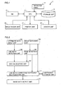
- Fig. 1 is a block diagram showing a specific example of a hardware configuration of an image forming apparatus 1 according to the embodiment.
- image forming apparatus 1 include a copier, a printer, an MFP (Multi Function Peripheral) having a function as a copier and a function as a printer, and the like. It is assumed in the embodiment that image forming apparatus 1 is an MFP.
- MFP Multi Function Peripheral
- image forming apparatus 1 includes a CPU (Central Processing Unit) 11 controlling image forming apparatus 1 totally, an image reader unit 19 reading image data from an original draft, a printer unit 21 outputting an image to a sheet of paper, an NIC (Network Interface Card) 15 serving as an expansion card for connecting image forming apparatus 1 to a network or a telephone line and carrying out local radio communication, a storage unit 13, such as an HD (Hard Disk) or a RAM (Random Access Memory), storing a job and a program, such as a line width control program, executed by CPU 11, an operation panel 17 serving as an interface between image forming apparatus 1 and a user, and a sensor unit 23 detecting a remaining amount of a consumable article.
- CPU Central Processing Unit
- image reader unit 19 reading image data from an original draft
- printer unit 21 outputting an image to a sheet of paper
- an NIC (Network Interface Card) 15 serving as an expansion card for connecting image forming apparatus 1 to a network or a telephone line and carrying out local radio communication
- Image forming apparatus 1 acquires original draft data containing image data and attribute data, performs line width control processing (to be described later), and outputs the image data.
- the outputted image data is printed in image formation processing.
- the image data contained in the original draft data acquired by image forming apparatus 1 is YMCK (Yellow Magenta Cyan Black) data or RGB (Red Green Blue) data.
- the attribute data indicates that each pixel in the image data is a text, a graphic or neither the text nor the graphic.
- the attribute data is added by an image creation application operated in a terminal such as a PC (Personal Computer) and, then, is transmitted to image forming apparatus 1 in some cases.
- the attribute data is added by image forming apparatus 1 in such a manner that image data read by image reader unit 19 of image forming apparatus 1 is determined by an area determination unit (not shown) in some cases.
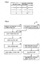
- Fig. 2 Functions shown in Fig. 2 are mainly realized in such a manner that CPU 11 executes programs stored in storage unit 13, but may be partially configured by hardware.
- the functions for performing the line width control processing in image forming apparatus 1 include an attribute data input unit 101 inputting attribute data of original draft data, an image data input unit 103 inputting image data of the original draft data, a line width detection unit 105 detecting a line width from the attribute data, an edge detection unit 109 detecting an edge from the image data, an AND calculation unit 107 calculating an AND of results of these detections, a coefficient storage unit 113 storing a coefficient for correcting the line width, a line width correction coefficient multiplication unit 111 performing a computation for correcting the line width, and an image data output unit 115 outputting image data having the corrected line width.
- Line width detection unit 105 performs line width detection processing (to be described later), and inputs a line width signal indicating a detected line width to AND calculation unit 107.
- Edge detection unit 109 performs edge detection processing (to be described later), and inputs an edge detection signal indicating a detected edge to AND calculation unit 107.
- AND calculation unit 107 calculates an AND of these signals, and calculates an edge line width.
- An edge line width signal indicating the calculated edge line width is inputted to line width correction coefficient multiplication unit 111.
- edge detection unit 109 performs the edge detection processing (to be described later), and inputs a PWM (Pulse Width Modulation) position control signal indicating a PWM position (to be described later) to line width correction coefficient multiplication unit 111.
- PWM Pulse Width Modulation
- Coefficient storage unit 113 is mainly formed by a predetermined area in storage unit 13, and stores a line width correction coefficient used by line width correction coefficient multiplication unit 111.
- the line width correction coefficient is a coefficient set for each of a 1-dot line width to an n-dot line width and used for correcting a line width such that the line width becomes an ideal line width upon formation of an image.
- coefficient storage unit 113 stores a line width correction coefficient in correspondence with a line width.
- the line width correction coefficient is a coefficient related to performance of an engine in an image forming apparatus as described above. Therefore, the line width correction coefficient is determined in correspondence with performance of an engine or is obtained from an experiment and the like. Hence, it is preferable that the line width correction coefficient is previously stored in coefficient storage unit 113. Alternatively, the line width correction coefficient may be changed or created by a user such as an administrator.
- a screen therefor is displayed on operation panel 17 in order to accept input of a specific numeric value.
- a settable range is previously determined in accordance with performance of an engine and a numeric value selected within the range is accepted. It is also preferable that acceptance of a numeric value deviated from the settable range is refused.
- Line width correction coefficient multiplication unit 111 performs processing for reading a line width correction coefficient corresponding to a line width from coefficient storage unit 113 on the basis of an edge line width signal inputted from AND calculation unit 107 and multiplying the line width by the coefficient, thereby correcting the line width.
- a result of the computation is inputted to image data output unit 115.
- Image data output unit 115 outputs image data having the corrected line width.
- edge detection unit 109 includes a primary differential filter computation unit 201 performing a primary differentiation on inputted image data through the use of a primary differential filter, a secondary differential filter computation unit 203 performing a secondary differentiation on inputted image data through the use of a secondary differential filter, an edge extraction unit 205 extracting a pixel, which is as an edge, on the basis of a result of these computations, an edge dilation unit 207 performing dilation processing on the pixel which is an edge, an edge erosion unit 209 performing erosion processing on a result of the processing, a PWM printing position code generation unit 211 generating a PWM printing position code for each pixel, a selector unit 213 selectively inputting a PWM printing position code, an edge signal output unit 215 outputting an edge signal on the basis of the PWM printing position code and a result of the erosion processing, and a PWM printing control signal output unit 217 outputting a PWM printing control signal on the basis of the PWM printing position code.
- Edge extraction unit 205 calculates an AND of a result of the computation performed on the image data by primary differential filter computation unit 201 through the use of the primary differential filter and a result of the computation performed on the image data by secondary differential filter computation unit 203 through the use of the secondary differential filter, and extracts an edge from the image data.
- the extracted edge is inputted to edge dilation unit 207.
- a method for extracting an edge in edge extraction unit 205 is not particularly limited in the present invention, and a typical method may be adopted in the present invention.
- Edge dilation unit 207 performs dilation processing on each edge inputted from edge extraction unit 205, and inputs a result of the processing to edge erosion unit 209.
- Edge erosion unit 209 performs erosion processing on each result of the dilation processing, and inputs a result of the processing to edge signal output unit 215.
- the dilation processing in edge dilation unit 207 and the erosion processing in edge erosion unit 209 are typical processing called open processing, and specific methods thereof are not particularly limited in the present invention.
- Edge signal output unit 215 inputs an edge detection signal indicating a pixel which is an edge to each of AND calculation unit 107 and selector unit 213 on the basis of a result of the processing in edge erosion unit 209.
- PWM printing position code generation unit 211 generates a PWM printing position code for determining a growth position of PWM with regard to each pixel in image data.
- the PWM printing position code corresponds to 2-bit data indicating a position, to which a pulse for dot printing is outputted, in one pixel if a gradation of a target pixel is smaller than a maximum value. That is, PWM printing position code generation unit 211 determines a position, at which dot printing is performed, in each pixel, in other words, determines a position and a direction, at and in which a dot printing portion is expanded, in one pixel.
- the term "a position and a direction, at and in which a dot printing portion is expanded, in one pixel” is referred to as "a growth position (or PWM position)", and a printing pulse for dot printing is outputted to the position.
- a target pixel has a gradation value of D1D.
- a pixel immediately preceding the target pixel has a gradation value of D0D and a pixel immediately following the target pixel has a gradation value of D2D.
- a ruled line contained in an original draft image is dark in color (e.g., black) on a background which is light in color (e.g., white).
- PWM printing position code generation unit 211 defines a relation in size among gradation values D0D, D1D and D2D.
- a growth position is defined as follows.
- PWM printing position code generation unit 211 defines a growth position such that a dot printing portion is expanded from a right side. If the pixel immediately preceding the target pixel has a concentration lower than that of the target pixel (the aforementioned cases (C) and (D)), as shown in Fig. 7 , PWM printing position code generation unit 211 defines a growth position such that a dot printing portion is expanded from a left side. If the target pixel has a concentration lower than those of the other two pixels (the aforementioned case (E)), as shown in Fig.
- PWM printing position code generation unit 211 defines a growth position such that a dot printing portion is expanded from both sides uniformly. Then, PWM printing position code generation unit 211 generates a PWM printing position code indicating a defined growth position, with regard to each pixel, and inputs the PWM printing position code to selector unit 213.
- Selector unit 213 performs signal input operations on the basis of an edge signal inputted from edge signal output unit 215 and a PWM printing position code inputted from PWM printing position code generation unit 211. More specifically, with regard to a pixel which is detected as an edge, selector unit 213 inputs a PWM printing control signal for performing dot printing on a defined position to line width correction coefficient multiplication unit 111 on the basis of the PWM printing position code. On the other hand, with regard to a pixel which is not detected as an edge, selector unit 213 inputs a PWM printing control signal for regarding a dot printing portion as a central position of the pixels to line width correction coefficient multiplication unit 111 on the basis of a printing position code stored previously.
- the aforementioned printing position code stored previously will be referred to as a central printing position code.
- line width detection unit 105 includes a line width correction target attribute selection unit 301 selecting attribute data, which is a target of processing for correcting a line width, from attribute data of respective pixels in image data, an erosion processing unit 303 performing erosion processing on the attribute data to be processed, a first dilation processing unit 305 performing first dilation processing on a result of the processing, an inner line width output unit 307 detecting an inner line width (to be described later) from a result of the first dilation processing, and outputting the detected inner line width, a second dilation processing unit 309 performing second dilation processing on the result of the erosion processing, and am outer line width output unit 311 detecting an outer line width (to be described later) from a result of the second dilation processing, and outputting the detected outer line width.
- attribute data which is a target of processing for correcting a line width, from attribute data of respective pixels in image data
- an erosion processing unit 303 performing erosion processing on the attribute data to be processed
- a first dilation processing unit 305 performing first dilation processing on a
- Line width correction target attribute selection unit 301 analyzes inputted attribute data, and determines that each pixel is a text, a graphic or neither the pixel nor the graphic. As a result, line width correction target attribute selection unit 301 selects attribute data concerning a pixel determined as a text and a pixel determined as a ruled line (graphic), as attribute data which is a target of processing for correcting a line width, and inputs the selected attribute data to erosion processing unit 303. Erosion processing unit 303 performs erosion processing on each attribute data, which is inputted as data to be processed and corresponds to each pixel, through the use of one of a filter formed from a one by one matrix of pixels to a filter formed from an "n" by "n” matrix of pixels.
- a result of the erosion processing is subjected to first dilation processing and second dilation processing in first dilation processing unit 305 and second dilation processing unit 309, respectively.
- Each of the erosion processing in erosion processing unit 303, the dilation processing in first dilation processing unit 305 and the dilation processing in second dilation processing unit 309 is typical processing called close processing. Therefore, a specific method of the processing is not particularly limited in the present invention.
- first dilation processing unit 305 performs dilation processing on a result of the processing in erosion processing unit 303 through the use of a filter having a size equal to that of the filter used in erosion processing unit 303.
- a result of the first dilation processing is inputted to inner line width output unit 307, and inner line width output unit 307 inputs an inner line width signal indicating an inner line width (to be described later) to AND calculation unit 107 on the basis of the result of the processing.
- second dilation processing unit 309 performs dilation processing on the result of the processing in erosion processing unit 303 through the use of a filter having a size larger by two pixels than that of the filter used in erosion processing unit 303.
- a result of the second dilation processing is inputted to outer line width output unit 311, and outer line width output unit 311 inputs an outer line width signal indicating an outer line width (to be described later) to AND calculation unit 107 on the basis of the result of the processing
- the first dilation processing unit 305 performs the first dilation processing on the result of the processing in erosion processing unit 303 through the use of the filter having a size equal to that of the filter used in erosion processing unit 303, a fine line which is not more than a filter size is eliminated, so that there is detected a black line BL having pixels which correspond to one pixel at both ends thereof as an edge pixel and are shown by portions E in Fig. 12 . Then, there is detected a width LA of the black line containing the edge pixels at the both ends thereof each having a width DA corresponding to a width of one pixel.
- width LA of the black line containing the widths of the two edge pixels (DA x 2) will be referred to as an inner line width.
- second dilation processing unit 309 performs the second dilation processing on the result of the processing in erosion processing unit 303 through the use of the filter having a size larger by two pixels than that of the filter used in erosion processing unit 303, there is detected a hollow line WH (hereinafter, referred to as a white line) which has pixels (portions E) corresponding to one pixel at both ends thereof as an edge pixel, with respect to a black background (portions BL) in Fig. 13 .
- a white line which has pixels (portions E) corresponding to one pixel at both ends thereof as an edge pixel, with respect to a black background (portions BL) in Fig. 13 .
- width LB of the white line containing the widths of the two edge pixels (DB x 2) will be referred to as an outer line width.
- a maximum size value "n" of the filter used in first dilation processing unit 305 and second dilation processing unit 309 is not limited to a specific numeric value in the present invention, and may be set at an optional numeric value.
- the specific numeric value may be preferably about 6 to 8; more preferably 7. It is preferred that if a line width is larger than a filter size, first dilation processing unit 305 and second dilation processing unit 309 output an error signal indicating the fact such that the aforementioned processing is not performed on the line width larger than the filter size.
- AND calculation unit 107 calculates an AND of an inner line width signal inputted from inner line width output unit 307 and an edge signal inputted from edge signal output unit 215 or calculates an AND of an outer line width signal inputted from outer line width output unit 311 and the edge signal inputted from edge signal output unit 215, so that a line width of an edge to be corrected is calculated.
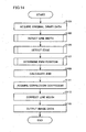
- the line width control processing (shown in a flowchart of Fig. 14 ) in image forming apparatus 1 according to the embodiment is realized in such a manner that CPU 11 of image forming apparatus 1 reads and executes the programs including the line width control program stored in storage unit 13 to control the respective units shown in Fig. 2 .
- CPU 11 acquires original draft data obtained by scanning with image reader unit 19 or original draft data obtained in such a manner that NIC 15 receives data transmitted from another apparatus (step S101).
- attribute data is inputted from attribute data input unit 101 and a line width is detected by line width detection unit 105 (step S103), so that a line width signal is outputted.
- image data is inputted from image data input unit 103 and an edge is detected by edge detection unit 109 (step S105).
- edge detection unit 109 determines a PWM position by edge detection unit 109 (step S107), and a PWM printing control signal based on the determined PWM position is outputted from PWM printing control signal output unit 217.
- AND calculation unit 107 calculates an AND of a line width signal outputted on the basis of the line width detected in step S105 and a PWM printing control signal outputted on the basis of the PWM position determined in step S107 (step S109), thereby to calculate a line width of the edge.
- line width correction coefficient multiplication unit 111 acquires a coefficient corresponding to the line width from line width correction coefficients stored in coefficient storage unit 113 (step S111) and performs a multiplication on the line width, thereby to calculate a corrected line width (step S113).
- CPU 11 performs image formation processing, so that a gradation of the pixel is replaced with a new gradation based on the corrected line width calculated in step S113.
- an image based on the image data in which a growth position of the pixel is determined is formed on the basis of a PWM printing control signal.
- the image data of the formed image is outputted to another apparatus through printer unit 21 or NIC 15 (step S115).
- line width correction target attribute selection unit 301 selects attribute data concerning a pixel determined as a text and attribute data concerning a pixel determined as a ruled line (graphic), as attribute data which is a target of processing for correcting a line width, from attribute data contained in original draft data (step S201).
- Erosion processing unit 303 performs erosion processing on the attribute data selected in step S201 through the use of one of a filter, formed from a one by one matrix of pixels to a filter formed from an "n" by "n” matrix of pixels (step S203). Further, first dilation processing unit 305 performs first dilation processing on a result of the processing through the use of a filter having a size equal to that of the filter used in erosion processing unit 303 (step S205). On the basis of a result of the first dilation processing in step S205, inner line width output unit 307 calculates an inner line width . as described above, and outputs an inner line width signal indicating the inner line width (step S207).
- second dilation processing unit 309 performs second dilation processing on the result of the erosion processing in step S203 through the use of a filter having a size larger by two pixels than that of the filter used in step S203 (step S209).
- outer line width output unit 311 calculates an outer line width as described above, and outputs an outer line width signal indicating the outer line width (step S211).
- steps S205 to S207 and the processing in steps S209 to S211 are independent of each other; therefore, a procedure thereof is not limited to the aforementioned procedure and may be performed in a retrograde order.
- step S205 to S207 and the processing in steps S209 to S211 are performed on each attribute data selected in step S201.
- the processing proceeds to step S105.
- step S105 With reference to Fig. 16 , next, description will be given of the edge detection processing in step S105.
- primary differential filter computation unit 201 performs a computation on image data contained in original draft data through the use of a primary differential filter (step S301).
- secondary differential filter computation, unit 203 performs a computation on the image data through the use of a secondary differential filter (step S303).
- the processing in step S301 and the processing in step S303 are independent of each other; therefore, a procedure thereof is not limited to the aforementioned procedure and may be performed in a retrograde order.
- edge extraction unit 205 extracts a pixel, which is an edge, from a result of the processing in step S301 and a result of processing in step S303 (step S305).
- Edge dilation unit 207 performs dilation processing on the edge pixel extracted in step S305 (step S307) and, further, edge erosion unit 209 performs erosion processing on a result of the processing (step S309).
- step S307 and the erosion processing in step S309 are performed on each pixel extracted as an edge in step S305.
- edge signal output unit, 215 Upon completion of performance of processing for all pixels extracted as an edge in step S305 (YES in step S311), edge signal output unit, 215 outputs an edge detection signal indicating an edge pixel (step S313) and the processing proceeds to step S 107.
- PWM printing position code generation unit 211 generates a PWM printing position code as described above with regard to each pixel in image data contained in original draft data (step S401).
- selector unit 213 determines whether or not the pixel having the PWM printing position code generated in step S401 is a pixel extracted as an edge, on the basis of the edge signal outputted from edge signal output unit 215 in step S313 (step S403). As a result, if the pixel is determined as a pixel extracted as an edge (YES in step S403), PWM printing control signal output unit 217 outputs a PWM printing control signal based on the PWM printing position code generated in step S401 (step S405). If not (NO in step S403), PWM printing control signal output unit 217 outputs a PWM printing control signal based on a central printing position code as described above (step S407).
- steps S401 to S407 is performed on all pixels in image data contained in the original draft data acquired in step S101. Upon completion of performance of processing for all pixels (YES in step S409), the processing proceeds to step S109.
- a PWM printing position code is generated with regard to all pixels contained in image data in step S401.
- a PWM printing position code may be generated with regard to only a pixel determined as an edge pixel through previous determination in step S403. That is, the processing procedure is not limited to the aforementioned order.
- Step S403 is performed prior to step S401 and, as a result of the determination, the PWM printing position code generation processing in step S401 may be performed.
- image forming apparatus 1 makes it possible to replace a gradation by a line width correction coefficient and to narrow a line width in a case that an edge portion of a character or a ruled line has a predetermined thickness. Thus, it is possible to suppress a phenomenon that an edge portion of a character or a ruled line becomes thick, which is caused due to engine characteristics of image forming apparatus 1. Thus, it is possible to enhance reproducibility of a fine line. As a result, image forming apparatus 1 can form an image of high quality.
- an image forming apparatus 1 includes a color detection unit 117 detecting a color from image data, in addition to the functions shown in Fig. 2 .
- Color detection unit 117 detects a color for each pixel in image data, and inputs a color detection signal indicating the detected color to a line width correction coefficient multiplication unit 111.
- a method for detecting a color from image data in color detection unit 117 is not particularly limited to a specific method in the present invention, and an optional method can be adopted in the present invention.
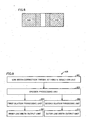
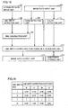
- a coefficient storage unit 113 of image forming apparatus 1 stores a line width correction coefficient set for each color with respect to each of a 1-dot line width to an n-dot line width. It is to be noted that a specific numeric value of the coefficient in Fig. 19 is merely one specific example; therefore, the present invention is not limited thereto.
- an edge detection unit 109 detects an edge from image data and color detection unit 117 detects a color for each pixel from the image data in step S105.
- step S111 line width correction coefficient multiplication unit 111 acquires a line width correction coefficient on the basis of a line width of the edge calculated in step S109 and a color of the edge detected in step S105.
- image forming apparatus 1 As one of engine characteristics, there is a case that expansion of a dot (enlargement of edge) differs for each color. Even in such a case, image forming apparatus 1 according to the first modification corrects a line width for each color through the use of a line width correction coeffcient set for each color. Thus, it is possible to suppress a phenomenon that an edge portion of a character or a ruled line becomes thick due to the engine characteristics of image forming apparatus 1. Further, it is possible to enhance reproducibility of a fine line. As a result, image forming apparatus 1 can form an image of high quality.
- an image forming apparatus 1 acquires original draft data and, also, acquires a mode of an original draft and language information about the original draft.
- the mode is information for specifying a type of an original draft, for example, for specifying that original draft data is document data, web data or CAD (Computer Aided Design) data.
- the mode may be automatically transmitted to image forming apparatus 1 together with the original draft data.
- the mode may be inputted to image forming apparatus 1 together with the original draft data.
- the mode may be different from the original draft data or may be contained in the original draft data. Alternatively, the mode may be part of attribute data contained in the original draft data.
- the language information is information representing a language of the original draft data.
- the language information may be acquired by image forming apparatus 1.
- the language information may be different from the original draft data or may be contained in the original draft data. Alternatively, the language data may be part of attribute data contained in the original draft data.
- data issues a printing command to thereby transmit the original draft data to image forming apparatus 1
- the mode or the language information of the original draft is created by a program (controller) for issuing a printing command to image forming apparatus 1 and is transmitted to image forming apparatus 1 together with the original draft data in accordance with execution of the program.
- the mode and the language information are inputted to a line width correction coefficient multiplication unit 111.
- a coefficient storage unit 113 of image forming apparatus 1 stores a line width correction coefficient set for each mode of the original draft and a line width correction coefficient set for each language of the original draft with respect to each of a 1-dot line width to an n-dot line width.
- line width correction coefficient multiplication unit 111 acquires a line width correction coefficient on the basis of a line width of an edge calculated in step S109 and the inputted mode or language information of the original draft.
- image forming apparatus 1 As one of engine characteristics, there is a case that expansion of a dot (enlargement of edge) differs for each mode or language information of the original draft. Even in such a case, image forming apparatus 1 according to the second modification corrects a line width through the use of a line width correction coefficient set for each mode or language information of the original draft. Thus, it is possible to suppress a phenomenon that an edge portion of a character or a ruled line becomes thick due to the engine characteristics of image forming apparatus 1. Further, it is possible to enhance reproducibility of a fine line. As a result, image forming apparatus 1 can form an image of high quality.
- the present invention can further provide a program for allowing a computer to execute the line width control according to the aforementioned embodiment.
- a program may be provided as a program product while being recorded in a computer readable recording medium such as a flexible disk attached to the computer, a CD-ROM (Compact Disk-Read Only Memory), a ROM (Read Only Memory), a RAM (Random Access Memory) or a memory card.
- the program may be provided while being recorded in a recording medium such as a hard disk in the computer.
- the program may be provided through a download on a network.
- the program according to the present invention may call a required module from among program modules provided as part of an OS (Operating System) of the computer in a predetermined arrangement at a predetermined timing, thereby to perform processing.
- the program itself includes no module; therefore, the processing is performed in cooperation with the OS.
- the program including no module is also subsumed under the program according to the present invention.
- the program according to the present invention may be provided while being incorporated in part of another program.
- the program itself includes no module; therefore, the processing is performed in cooperation with another program including a module.
- the program incorporated in another program is also subsumed under the program according to the present invention.
- a program product to be provided is executed while being installed in a program storage unit such as a hard disk.
- the program product includes a program itself and a recording medium having the program recorded therein.
Landscapes
- Engineering & Computer Science (AREA)
- Multimedia (AREA)
- Signal Processing (AREA)
- Image Processing (AREA)
- Facsimile Image Signal Circuits (AREA)
Claims (15)
- Eine Bilderzeugungsvorrichtung, umfassend:eine Linienbreiten-Detektionseinheit (105), ausgebildet zum Detektieren einer Breite einer in Bilddaten enthaltenen Linie aus zu den Bilddaten zugehörigen Attributdaten, wobei das Detektieren ein Auswählen von Attributdaten, welche ein Ziel einer Verarbeitung zum Korrigieren einer Linienbreite sind, aus den Attributdaten umfasst;eine Randdetektionseinheit (109), ausgebildet zum Detektieren eines Randpixels aus den Bilddaten;eine Speichereinheit (113), ausgebildet zum Speichern eines zu einer Linienbreite gehörenden Linienbreiten-Korrekturkoeffizienten; undeine Korrektureinheit (111), ausgebildet zum Erfassen eines Linienbreiten-Korrekturkoeffizienten, welcher zu einer durch die Linienbreiten-Detektionseinheit detektierten Linienbreite gehört, aus der Speichereinheit mit Bezug zu dem Randpixel undausgebildet zum Korrigieren einer Abstufung des Randpixels durch die Verwendung der Linienbreite und des Linienbreiten-Korrekturkoeffizienten, wodurch die Linienbreite korrigiert wird;wobeidie Linienbreiten-Detektionseinheit umfasst:eine Erosionsverarbeitungseinheit (303), ausgebildet zum Ausführen einer Erosionsverarbeitung an den Attributdaten durch die Verwendung eines von einem Filter, welcher aus einer eins-mal-eins Pixelmatrix gebildet ist, bis zu einem Filter, welcher aus einer "n"-mal-"n" Pixelmatrix gebildet ist;eine erste Dilatationsverarbeitungseinheit (305), ausgebildet zum Ausführen einer Dilatationsverarbeitung an der Erosionsverarbeitung unter Verwendung des aus jeder Pixelmatrix gebildeten Filters durch die Verwendung eines Filters mit einer Größe gleich der des Filters, welcher in der Erosionsverarbeitung verwendet ist;eine zweite Dilatationsverarbeitungseinheit (309), ausgebildet zum Ausführen einer Dilatationsverarbeitung an der Erosionsverarbeitung unter Verwendung des aus jeder Pixelmatrix gebildeten Filters durch die Verwendung eines Filters mit einer um zwei Pixel größeren Größe als der des Filters, welcher in der Erosionsverarbeitung verwendet ist; undeine Linienbreiten-Ausgabeeinheit (307, 311), ausgebildet zum Ausgeben einer ersten Linienbreite als ein Ergebnis der Verarbeitung in der ersten Dilatationsverarbeitungseinheit und einer zweiten Linienbreite als ein Ergebnis der Verarbeitung in der zweiten Dilatationsverarbeitungseinheit.
- Bilderzeugungsvorrichtung gemäß Anspruch 1, wobei
die Größe des Filters, welcher in der Erosionsverarbeitung verwendet ist, einen optional einstellbaren Maximalwert "n" aufweist und,
wenn die Linienbreite größer als die maximale Größe "n" ist, die Erosionsverarbeitungseinheit keine Erosionsverarbeitung ausführt. - Bilderzeugungsvorrichtung gemäß Anspruch 1, wobei die Randdetektionseinheit umfasst:eine Primärdifferenzialberechnungseinheit (201), ausgebildet zum Ausführen einer primären Differenzierung an den Bilddaten;eine Sekundärdifferenzialberechnungseinheit (203), ausgebildet zum Ausführen einer sekundären Differenzierung an den Bilddaten;eine Randdilatationsverarbeitungseinheit (207), ausgebildet zum Ausführen einer Dilatationsverarbeitung an einem UND eines Ergebnisses der primären Differenzierung und eines Ergebnisses der sekundären Differenzierung;eine Randerosionsverarbeitungseinheit (209), ausgebildet zum Ausführen einer Erosionsverarbeitung an einem Ergebnis der Dilatationsverarbeitung;eine Erzeugungseinheit (211), ausgebildet zum Erzeugen, mit Bezug zu einem Pixel der Bilddaten, eines PWM-Druckpositions-Codes, welcher angibt, dass ein Wachstum eines Druckpunkts von einem von Pixeln beginnt, welche jeweils zu dem relevanten Pixel in einer Hauptscanrichtung angrenzen, auf der Basis eines Unterschieds in einer Abstufung zwischen dem relevanten Pixel und den jeweils dazu angrenzenden Pixeln; undeine Auswahleinheit (213), ausgebildet zum Auswählen eines Codes, welcher eine Druckpulsausgabeposition in dem Pixel steuert, aus dem durch die Erzeugungseinheit erzeugten PWM-Druckpositions-Code und einem Zentral-Druckpositions-Code, welcher angibt, dass die Druckpulsausgabeposition des Pixels als eine Mitte des Pixels betrachtet wird, auf der Basis eines Ergebnis der Erosionsverarbeitung.
- Bilderzeugungsvorrichtung gemäß Anspruch 1, weiter umfassend:eine Farbdetektionseinheit (117), ausgebildet zum Detektieren einer Farbe der Linie aus den Bilddaten, wobeidie Speichereinheit zum Speichern eines zu einer Linienbreite gehörenden Linienbreiten-Korrekturkoeffizienten für jede Farbe ausgebildet istunddie Korrektureinheit ausgebildet ist zum Erfassen eines Linienbreiten-Korrekturkoeffizienten, welcher zu der durch die Linienbreiten-Detektionseinheit detektierten Linienbreite und der durch die Farbdetektionseinheit detektierten Farbe gehört, aus der Speichereinheit mit Bezug zu dem Randpixel und zum Korrigieren der Abstufung des Randpixels durch das Verwenden der Linienbreite und des Linienbreiten-Korrekturkoeffizienten, wodurch die Linienbreite korrigiert wird.
- Bilderzeugungsvorrichtung gemäß Anspruch 1, wobei
die Speichereinheit zum Speichern eines zu einer Linienbreite gehörenden Linienbreiten-Korrekturkoeffizienten für jeden Modus und/oder jede Sprache der Bildschirmdaten ausgebildet ist, und
die Korrektureinheit ausgebildet ist zum Erfassen eines Linienbreiten-Korrekturkoeffizienten, welcher zu der durch die Linienbreiten-Detektionseinheit detektierten Linienbreite und dem Modus und/oder der Sprache der Bilddaten gehört, aus der Speichereinheit mit Bezug zu dem Randpixel, und zum Korrigieren der Abstufung des Randpixels durch das Verwenden der Linienbreite und des Linienbreiten-Korrekturkoeffizienten, wodurch die Linienbreite korrigiert wird. - Ein Linienbreiten-Steuerverfahren zum Steuern einer Breite einer in einem durch eine Bilderzeugungsvorrichtung erzeugten Bild enthaltenen Linie, welche eine zum Speichern eines zu einer Linienbreite gehörenden Linienbreiten-Korrekturkoeffizienten ausgebildete Speichereinheit umfasst, wobei das Linienbreiten-Steuerverfahren umfasst:einen Erfassungsschritt (S101) zum Erfassen von Bilddaten und zu den Bilddaten gehörenden Attributdaten in der Bilderzeugungsvorrichtung;einen Linienbreiten-Detektionsschritt (S103) zum Detektieren einer Breite einer in den Bilddaten enthaltenen Linie aus den Attributdaten, wobei das Detektieren ein Auswählen von Attributdaten, welche ein Ziel einer Verarbeitung zum Korrigieren einer Linienbreite sind, aus den Attributdaten umfasst;einen Randdetektionsschritt (S105) zum Detektieren eines Randpixels aus den Bilddaten; undeinen Korrekturschritt (S111, S113) zum Erfassen eines Linienbreiten-Korrekturkoeffizienten, welcher zu der in dem Linienbreiten-Detektionsschritt detektierten Linienbreite gehört, aus der Speichereinheit mit Bezug zu dem Randpixel und zum Korrigieren einer Abstufung des Randpixels durch die Verwendung der Linienbreite und des Linienbreiten-Korrekturkoeffizienten, wodurch die Linienbreite korrigiert wird;wobeider Linienbreiten-Detektionsschritt umfasst:einen Erosionsverarbeitungsschritt (S203) zum Ausführen einer Erosionsverarbeitung an den Attributdaten durch die Verwendung eines von einem Filter, welcher aus einer eins-mal-eins Pixelmatrix gebildet ist, bis zu einem Filter, welcher aus einer "n"-mal-"n" Pixelmatrix gebildet ist;einen ersten Dilatationsverarbeitungsschritt (S205) zum Ausführen einer Dilatationsverarbeitung an der Erosionsverarbeitung unter Verwendung des aus jeder Pixelmatrix gebildeten Filters durch die Verwendung eines Filters mit einer Größe gleich der des Filters, welcher in der Erosionsverarbeitung verwendet ist;einen zweiten Dilatationsverarbeitungsschritt (S209) zum Ausführen einer Dilatationsverarbeitung an der Erosionsverarbeitung unter Verwendung des aus jeder Pixelmatrix gebildeten Filters durch die Verwendung eines Filters mit einer um zwei Pixel größeren Größe als der des Filters, welcher in der Erosionsverarbeitung verwendet ist; undeinen Linienbreiten-Ausgabeschritt (S207, S211) zum Ausgeben einer ersten Linienbreite als ein Ergebnis der Verarbeitung in dem ersten Dilatationsverarbeitungsschritt und einer zweiten Linienbreite als ein Ergebnis der Verarbeitung in dem zweiten Dilatationsverarbeitungsschritt.
- Linienbreiten-Steuerverfahren gemäß Anspruch 6, wobei die Größe des Filters, welcher in der Erosionsverarbeitung verwendet ist, einen optional einstellbaren Maximalwert "n" aufweist und,
wenn die Linienbreite größer als der Maximalwert "n" ist, der Erosionsverarbeitungsschritt keine Erosionsverarbeitung ausführt. - Linienbreiten-Steuerverfahren gemäß Anspruch 6, wobei der Randdetektionsschritt umfasst:einen Primärdifferenzialberechnungsschritt (S301) zum Ausführen einer primären Differenzierung an den Bilddaten;einen Sekundärdifferenzialberechnungsschritt (S303) zum Ausführen einer sekundären Differenzierung an den Bilddaten;einen Randentnahmeschritt (S305) zum Berechnen eines UND eines Ergebnisses der primären Differenzierung und eines Ergebnisses der sekundären Differenzierung, wodurch ein Randpixel aus den Bilddaten entnommen wird;einen Randdilatations-Verarbeitungsschritt (S307) zum Ausführen einer Dilatationsverarbeitung an dem UND des Ergebnisses der primären Differenzierung und des Ergebnisses der sekundären Differenzierung mit Bezug zu einem als das Randpixel entnommenen Pixel;einen Randerosions-Verarbeitungsschritt (S309) zum Ausführen einer Erosionsverarbeitung an einem Ergebnis der Dilatationsverarbeitung;einen Erzeugungsschritt (S401) zum Erzeugen, mit Bezug zu einem Pixel der Bilddaten, eines PWM-Druckpositions-Codes, welcher angibt, dass ein Wachstum eines Druckpunkts von einem von Pixeln beginnt, welche jeweils zu dem relevanten Pixel in einer Hauptscanrichtung angrenzen, auf der Basis eines Unterschieds in einer Abstufung zwischen dem relevanten Pixel und den jeweils dazu angrenzenden Pixeln;einen ersten Ausgabeschritt (S405) zum Ausgeben des in dem Erzeugungsschritt erzeugten PWM-Druckpositions-Codes als einen Code, welcher eine Druckpulsausgabeposition in dem Pixel steuert, wenn das Pixel als ein Randpixel detektiert ist, auf der Basis eines Ergebnisses der Erosionsverarbeitung; undeinen zweiten Ausgabeschritt (S407) zum Ausgeben eines Zentral-Druckpositions-Codes, welcher angibt, dass die Druckpulsausgabeposition des Pixels als eine Mitte des Pixels betrachtet wird, als den Code, welcher die Druckpulsausgabeposition in dem Pixel steuert, wenn das Pixel nicht als ein Randpixel detektiert ist, auf der Basis des Ergebnisses der Erosionsverarbeitung.
- Linienbreiten-Steuerverfahren gemäß Anspruch 6, wobei
die Speichereinheit einen zu einer Linienbreite gehörenden Linienbreiten-Korrekturkoeffizienten für jede Farbe speichert,
das Linienbreiten-Steuerverfahren weiter einen Farbdetektionsschritt (S105) zum Detektieren einer Farbe der Linie aus den Bilddaten umfasst, und
der Korrekturschritt einen Linienbreiten-Korrekturkoeffizienten erfasst, welcher zu der in dem Linienbreiten-Detektionsschritt detektierten Linienbreite und der in dem Farbdetektionsschritt detektierten Farbe gehört, aus der Speichereinheit mit Bezug zu dem Randpixel und die Abstufung des Randpixels durch das Verwenden der Linienbreite und des Linienbreiten-Korrekturkoeffizienten korrigiert, um dadurch die Linienbreite zu korrigieren. - Linienbreiten-Steuerverfahren gemäß Anspruch 6, wobei
die Speichereinheit einen Linienbreiten-Korrekturkoeffizienten, welcher zu einer Linienbreite für jeden Modus und/oder jede Sprache der Bilddaten gehört, speichert und
der Korrekturschritt einen Linienbreiten-Korrekturkoeffizienten erfasst, welcher zu der in dem Linienbreiten-Detektionsschritt detektierten Linienbreite und dem Modus und/oder der Sprache der Bilddaten gehört, aus der Speichereinheit mit Bezug zu dem Randpixel und die Abstufung des Randpixels durch das Verwenden der Linienbreite und des Linienbreiten-Korrekturkoeffizienten korrigiert, um dadurch die Linienbreite zu korrigieren. - Ein Linienbreiten-Steuerprogramm zum Ermöglichen, dass ein Computer eine Verarbeitung zum Steuern einer Breite einer in einem erzeugten Bild enthaltenen Linie ausführt, wobei das Linienbreiten-Steuerprogramm umfasst:einen Erfassungsschritt (S101) zum Erfassen von Bilddaten und zu den Bilddaten gehörenden Attributdaten;einen Linienbreiten-Detektionsschritt (S103) zum Detektieren einer Breite einer in den Bilddaten enthaltenen Linie aus den Attributdaten, wobei das Detektieren ein Auswählen von Attributdaten, welche ein Ziel einer Verarbeitung zum Korrigieren einer Linienbreite sind, aus den Attributdaten umfasst;einen Randdetektionsschritt (S105) zum Detektieren eines Randpixels aus den Bilddaten; undeinen Korrekturschritt (S111, S113) zum Erfassen eines Linienbreiten-Korrekturkoeffizienten, welcher zu der in dem Linienbreiten-Detektionsschritt detektierten Linienbreite gehört, aus einer Speichereinheit zum Speichern eines zu einer Linienbreite gehörenden Linienbreiten-Korrekturkoeffizienten mit Bezug zu dem Randpixel und zum Korrigieren einer Abstufung des Randpixels durch die Verwendung der Linienbreite und des Linienbreiten-Korrekturkoeffizienten, wodurch die Linienbreite korrigiert wird;wobeider Linienbreiten-Detektionsschritt umfasst:einen Erosionsverarbeitungsschritt (S203) zum Ausführen einer Erosionsverarbeitung an den Attributdaten durch die Verwendung eines von einem Filter, welcher aus einer eins-mal-eins Pixelmatrix gebildet ist, bis zu einem Filter, welcher aus einer "n"-mal-"n" Pixelmatrix gebildet ist;einen ersten Dilatationsverarbeitungsschritt (S205) zum Ausführen einer Dilatationsverarbeitung an der Erosionsverarbeitung unter Verwendung des aus jeder Pixelmatrix gebildeten Filters durch die Verwendung eines Filters mit einer Größe gleich der des Filters, welcher in der Erosionsverarbeitung verwendet ist;einen zweiten Dilatationsverarbeitungsschritt (S209) zum Ausführen einer Dilatationsverarbeitung an der Erosionsverarbeitung unter Verwendung des aus jeder Pixelmatrix gebildeten Filters durch die Verwendung eines Filters mit einer um zwei Pixel größeren Größe als der des Filters, welcher in der Erosionsverarbeitung verwendet ist; undeinen Linienbreiten-Ausgabeschritt (S207, S211) zum Ausgeben einer ersten Linienbreite als ein Ergebnis der Verarbeitung in dem ersten Dilatationsverarbeitungsschritt und einer zweiten Linienbreite als ein Ergebnis der Verarbeitung in dem zweiten Dilatationsverarbeitungsschritt.
- Linienbreiten-Steuerprogramm gemäß Anspruch 11, wobei
die Größe des Filters, welcher in der Erosionsverarbeitung verwendet ist, einen optional einstellbaren Maximalwert "n" aufweist und,
wenn die Linienbreite größer als der Maximalwert "n" ist, der Erosionsverarbeitungsschritt keine Erosionsverarbeitung ausführt. - Linienbreiten-Steuerprogramm gemäß Anspruch 11, wobei der Randdetektionsschritt umfasst:einen Primärdifferenzialberechnungsschritt (S301) zum Ausführen einer primären Differenzierung an den Bilddaten;einen Sekundärdifferenzialberechnungsschritt (S303) zum Ausführen einer sekundären Differenzierung an den Bilddaten;einen Randentnahmeschritt (S305) zum Berechnen eines UND eines Ergebnisses der primären Differenzierung und eines Ergebnisses der sekundären Differenzierung, wodurch ein Randpixel aus den Bilddaten entnommen wird;einen Randdilatations-Verarbeitungsschritt (S307) zum Ausführen einer Dilatationsverarbeitung an dem UND des Ergebnisses der primären Differenzierung und des Ergebnisses der sekundären Differenzierung mit Bezug zu einem als das Randpixel entnommenen Pixel;einen Randerosions-Verarbeitungsschritt (S309) zum Ausführen einer Erosionsverarbeitung an einem Ergebnis der Dilatationsverarbeitung;einen Erzeugungsschritt (S401) zum Erzeugen, mit Bezug zu einem Pixel der Bilddaten, eines PWM-Druckpositions-Codes, welcher angibt, dass ein Wachstum eines Druckpunkts von einem von Pixeln beginnt, welche jeweils zu dem relevanten Pixel in einer Hauptscanrichtung angrenzen, auf der Basis eines Unterschieds in einer Abstufung zwischen dem relevanten Pixel und den jeweils dazu angrenzenden Pixeln;einen ersten Ausgabeschritt (S405) zum Ausgeben des in dem Erzeugungsschritt erzeugten PWM-Druckpositions-Codes als einen Code, welcher eine Druckpulsausgabeposition in dem Pixel steuert, wenn das Pixel als ein Randpixel detektiert ist, auf der Basis eines Ergebnisses der Erosionsverarbeitung; undeinen zweiten Ausgabeschritt (S407) zum Ausgeben eines Zentral-Druckpositions-Codes, welcher angibt, dass die Druckpulsausgabeposition des Pixels als eine Mitte des Pixels betrachtet wird, als den Code, welcher die Druckpulsausgabeposition in dem Pixel steuert, wenn das Pixel nicht als ein Randpixel auf der Basis des Ergebnisses der Erosionsverarbeitung detektiert ist.
- Linienbreiten-Steuerprogramm gemäß Anspruch 11, wobei die Speichereinheit einen zu einer Linienbreite gehörenden Linienbreiten-Korrekturkoeffizienten für jede Farbe speichert,
das Linienbreiten-Steuerprogramm weiter einen Farbdetektionsschritt (S105) zum Detektieren einer Farbe der Linie aus den Bilddaten umfasst, und
der Korrekturschritt einen Linienbreiten-Korrekturkoeffizienten erfasst, welcher zu der in dem Linienbreiten-Detektionsschritt detektierten Linienbreite und der in dem Farbdetektionsschritt detektierten Farbe gehört, aus der Speichereinheit mit Bezug zu dem Randpixel und die Abstufung des Randpixels durch das Verwenden der Linienbreite und des Linienbreiten-Korrekturkoeffizienten korrigiert, um dadurch die Linienbreite zu korrigieren. - Linienbreiten-Steuerprogramm gemäß Anspruch 11, wobei
die Speichereinheit einen Linienbreiten-Korrekturkoeffizienten, welcher zu einer Linienbreite für jeden Modus und/oder jede Sprache der Bilddaten gehört, speichert und
der Korrekturschritt einen Linienbreiten-Korrekturkoeffizienten erfasst, welcher zu der in dem Linienbreiten-Detektionsschritt detektierten Linienbreite und dem Modus und/oder der Sprache der Bilddaten gehört, aus der Speichereinheit mit Bezug zu dem Randpixel und die Abstufung des Randpixels durch das Verwenden der Linienbreite und des Linienbreiten-Korrekturkoeffizienten korrigiert, um dadurch die Linienbreite zu korrigieren.
Applications Claiming Priority (1)
| Application Number | Priority Date | Filing Date | Title |
|---|---|---|---|
| JP2006321871A JP4270266B2 (ja) | 2006-11-29 | 2006-11-29 | 画像形成装置、線幅制御方法、および線幅制御プログラム |
Publications (2)
| Publication Number | Publication Date |
|---|---|
| EP1928165A1 EP1928165A1 (de) | 2008-06-04 |
| EP1928165B1 true EP1928165B1 (de) | 2016-07-27 |
Family
ID=38016785
Family Applications (1)
| Application Number | Title | Priority Date | Filing Date |
|---|---|---|---|
| EP07004034.0A Ceased EP1928165B1 (de) | 2006-11-29 | 2007-02-27 | Bilderzeugungsvorrichtung mit Funktion zur Reproduktion hochqualitativer feiner Linien |
Country Status (3)
| Country | Link |
|---|---|
| US (1) | US8355175B2 (de) |
| EP (1) | EP1928165B1 (de) |
| JP (1) | JP4270266B2 (de) |
Families Citing this family (7)
| Publication number | Priority date | Publication date | Assignee | Title |
|---|---|---|---|---|
| KR101180059B1 (ko) * | 2007-05-11 | 2012-09-04 | 삼성전자주식회사 | 화상형성장치 및 그 방법 |
| JP4491488B2 (ja) * | 2008-03-03 | 2010-06-30 | シャープ株式会社 | 画像処理装置、画像読取装置、画像データ出力処理装置、および画像処理方法 |
| JP5623063B2 (ja) * | 2009-11-16 | 2014-11-12 | キヤノン株式会社 | 画像処理装置およびその方法 |
| US8699813B2 (en) * | 2010-11-19 | 2014-04-15 | Analog Devices, Inc | Adaptive filter for low-light noise reduction |
| JP5769415B2 (ja) * | 2010-12-28 | 2015-08-26 | キヤノン株式会社 | 画像形成装置 |
| JP2012170002A (ja) * | 2011-02-16 | 2012-09-06 | Canon Inc | 画像処理装置、画像処理方法、およびその画像処理プログラム |
| JP5896203B2 (ja) * | 2011-07-22 | 2016-03-30 | 富士ゼロックス株式会社 | 画像処理装置、画像形成装置およびプログラム |
Family Cites Families (14)
| Publication number | Priority date | Publication date | Assignee | Title |
|---|---|---|---|---|
| JP2598598B2 (ja) * | 1992-02-18 | 1997-04-09 | ライノタイプ−ヘル アクチエンゲゼルシャフト | 記録装置を露光較正する方法および装置 |
| JP3255971B2 (ja) | 1992-07-06 | 2002-02-12 | 株式会社リコー | 画像読取装置 |
| JP3599367B2 (ja) * | 1993-12-29 | 2004-12-08 | キヤノン株式会社 | 画像処理装置およびその方法 |
| JP2964931B2 (ja) * | 1995-04-25 | 1999-10-18 | 富士ゼロックス株式会社 | 画像処理装置および画像形成装置 |
| JP3613493B2 (ja) * | 1995-09-20 | 2005-01-26 | 株式会社リコー | カラー画像形成装置及びカラー画像形成方法 |
| JP3868441B2 (ja) | 1995-09-20 | 2007-01-17 | 株式会社リコー | カラー画像形成装置及びカラー画像形成方法 |
| US6167166A (en) * | 1998-03-23 | 2000-12-26 | Xerox Corporation | Method to enable the recognition and rendering of antialiased images |
| JP2000036912A (ja) | 1998-07-17 | 2000-02-02 | Toshiba Corp | 画像処理方法 |
| JP2000043319A (ja) * | 1998-07-29 | 2000-02-15 | Minolta Co Ltd | 画像形成装置 |
| JP3679621B2 (ja) * | 1998-09-14 | 2005-08-03 | 株式会社リコー | 画像形成装置 |
| US6834124B1 (en) * | 2000-10-16 | 2004-12-21 | Xerox Corporation | Adaptive image enhancement filter |
| US7046395B2 (en) * | 2001-12-26 | 2006-05-16 | Kabushiki Kaisha Toshiba | Image forming apparatus |
| JP2006180380A (ja) | 2004-12-24 | 2006-07-06 | Fuji Xerox Co Ltd | 線境界補正装置、画像処理装置、線境界補正方法 |
| JP4498233B2 (ja) * | 2005-06-30 | 2010-07-07 | キヤノン株式会社 | 画像処理装置および画像処理方法 |
-
2006
- 2006-11-29 JP JP2006321871A patent/JP4270266B2/ja not_active Expired - Fee Related
-
2007
- 2007-02-27 EP EP07004034.0A patent/EP1928165B1/de not_active Ceased
- 2007-03-22 US US11/723,943 patent/US8355175B2/en not_active Expired - Fee Related
Also Published As
| Publication number | Publication date |
|---|---|
| JP4270266B2 (ja) | 2009-05-27 |
| US8355175B2 (en) | 2013-01-15 |
| JP2008134912A (ja) | 2008-06-12 |
| EP1928165A1 (de) | 2008-06-04 |
| US20080123141A1 (en) | 2008-05-29 |
Similar Documents
| Publication | Publication Date | Title |
|---|---|---|
| CN102647535B (zh) | 图像处理装置及图像处理方法 | |
| JP4872860B2 (ja) | 画像処理装置及び画像処理方法 | |
| EP1871088A2 (de) | Verfahren und Vorrichtung zur Bildverarbeitung | |
| US8355175B2 (en) | Image forming apparatus capable of reproducing fine line of high quality | |
| JP2004151832A (ja) | 印刷製版における検版 | |
| US8638467B2 (en) | Print data generating apparatus a print data generating method | |
| JP2008011269A (ja) | 画像処理装置、画像処理方法、及び画像処理プログラム | |
| KR101810285B1 (ko) | 화상 처리 장치, 화상 처리 방법 및 컴퓨터 프로그램 | |
| US20090109509A1 (en) | Image processor and image processing method | |
| JP4684959B2 (ja) | 画像処理装置、画像処理方法およびプログラム | |
| US6343194B1 (en) | Printer controller and printer as well as recording method for controlling specific consumables used therefor | |
| JP5499981B2 (ja) | 画像処理装置 | |
| JP4569702B2 (ja) | 画像形成装置、線幅制御方法、および線幅制御プログラム | |
| JP2005316237A (ja) | 印刷制御装置、印刷制御方法および印刷制御プログラム | |
| JPH09149281A (ja) | カラー画像形成装置 | |
| US8335016B2 (en) | Image processing apparatus and program product using index vale or presentation image to decide consumption of recording material | |
| JP7381211B2 (ja) | 画像処理装置および画像処理方法 | |
| US8081343B2 (en) | Image forming system and computer readable medium storing image forming program | |
| JP2007088741A (ja) | 画像処理装置および画像処理方法 | |
| US10798267B2 (en) | Image processing to set output pixel values subject to edge or thin line correction | |
| JP2006210981A (ja) | 画像処理装置、画像処理システム、画像処理方法、画像処理プログラムおよび画像処理プログラムを記録した記録媒体 | |
| US10671897B2 (en) | Image processing apparatus | |
| JP2005275787A (ja) | 画像処理方法及び装置並びにプリンタ | |
| JP2021053828A (ja) | 画像処理装置 | |
| JP2007055032A (ja) | 印刷装置 |
Legal Events
| Date | Code | Title | Description |
|---|---|---|---|
| PUAI | Public reference made under article 153(3) epc to a published international application that has entered the european phase |
Free format text: ORIGINAL CODE: 0009012 |
|
| 17P | Request for examination filed |
Effective date: 20071026 |
|
| AK | Designated contracting states |
Kind code of ref document: A1 Designated state(s): AT BE BG CH CY CZ DE DK EE ES FI FR GB GR HU IE IS IT LI LT LU LV MC NL PL PT RO SE SI SK TR |
|
| AX | Request for extension of the european patent |
Extension state: AL BA HR MK RS |
|
| AKX | Designation fees paid |
Designated state(s): DE FR GB |
|
| 17Q | First examination report despatched |
Effective date: 20120622 |
|
| GRAP | Despatch of communication of intention to grant a patent |
Free format text: ORIGINAL CODE: EPIDOSNIGR1 |
|
| INTG | Intention to grant announced |
Effective date: 20160217 |
|
| GRAS | Grant fee paid |
Free format text: ORIGINAL CODE: EPIDOSNIGR3 |
|
| GRAA | (expected) grant |
Free format text: ORIGINAL CODE: 0009210 |
|
| AK | Designated contracting states |
Kind code of ref document: B1 Designated state(s): DE FR GB |
|
| REG | Reference to a national code |
Ref country code: GB Ref legal event code: FG4D |
|
| REG | Reference to a national code |
Ref country code: DE Ref legal event code: R096 Ref document number: 602007047145 Country of ref document: DE |
|
| REG | Reference to a national code |
Ref country code: FR Ref legal event code: PLFP Year of fee payment: 11 |
|
| REG | Reference to a national code |
Ref country code: DE Ref legal event code: R097 Ref document number: 602007047145 Country of ref document: DE |
|
| PLBE | No opposition filed within time limit |
Free format text: ORIGINAL CODE: 0009261 |
|
| STAA | Information on the status of an ep patent application or granted ep patent |
Free format text: STATUS: NO OPPOSITION FILED WITHIN TIME LIMIT |
|
| 26N | No opposition filed |
Effective date: 20170502 |
|
| REG | Reference to a national code |
Ref country code: FR Ref legal event code: PLFP Year of fee payment: 12 |
|
| P01 | Opt-out of the competence of the unified patent court (upc) registered |
Effective date: 20230510 |
|
| PGFP | Annual fee paid to national office [announced via postgrant information from national office to epo] |
Ref country code: DE Payment date: 20231229 Year of fee payment: 18 Ref country code: GB Payment date: 20240108 Year of fee payment: 18 |
|
| PGFP | Annual fee paid to national office [announced via postgrant information from national office to epo] |
Ref country code: FR Payment date: 20240103 Year of fee payment: 18 |
|
| REG | Reference to a national code |
Ref country code: DE Ref legal event code: R119 Ref document number: 602007047145 Country of ref document: DE |
|
| GBPC | Gb: european patent ceased through non-payment of renewal fee |
Effective date: 20250227 |
|
| PG25 | Lapsed in a contracting state [announced via postgrant information from national office to epo] |
Ref country code: DE Free format text: LAPSE BECAUSE OF NON-PAYMENT OF DUE FEES Effective date: 20250902 |
|
| PG25 | Lapsed in a contracting state [announced via postgrant information from national office to epo] |
Ref country code: GB Free format text: LAPSE BECAUSE OF NON-PAYMENT OF DUE FEES Effective date: 20250227 |
|
| PG25 | Lapsed in a contracting state [announced via postgrant information from national office to epo] |
Ref country code: FR Free format text: LAPSE BECAUSE OF NON-PAYMENT OF DUE FEES Effective date: 20250228 |