EP1923626A1 - Module DEL avec commande intégrée - Google Patents
Module DEL avec commande intégrée Download PDFInfo
- Publication number
- EP1923626A1 EP1923626A1 EP07118261A EP07118261A EP1923626A1 EP 1923626 A1 EP1923626 A1 EP 1923626A1 EP 07118261 A EP07118261 A EP 07118261A EP 07118261 A EP07118261 A EP 07118261A EP 1923626 A1 EP1923626 A1 EP 1923626A1
- Authority
- EP
- European Patent Office
- Prior art keywords
- led
- led module
- components
- housing
- control unit
- Prior art date
- Legal status (The legal status is an assumption and is not a legal conclusion. Google has not performed a legal analysis and makes no representation as to the accuracy of the status listed.)
- Granted
Links
Images


Classifications
-
- F—MECHANICAL ENGINEERING; LIGHTING; HEATING; WEAPONS; BLASTING
- F21—LIGHTING
- F21S—NON-PORTABLE LIGHTING DEVICES; SYSTEMS THEREOF; VEHICLE LIGHTING DEVICES SPECIALLY ADAPTED FOR VEHICLE EXTERIORS
- F21S45/00—Arrangements within vehicle lighting devices specially adapted for vehicle exteriors, for purposes other than emission or distribution of light
- F21S45/40—Cooling of lighting devices
- F21S45/47—Passive cooling, e.g. using fins, thermal conductive elements or openings
-
- F—MECHANICAL ENGINEERING; LIGHTING; HEATING; WEAPONS; BLASTING
- F21—LIGHTING
- F21K—NON-ELECTRIC LIGHT SOURCES USING LUMINESCENCE; LIGHT SOURCES USING ELECTROCHEMILUMINESCENCE; LIGHT SOURCES USING CHARGES OF COMBUSTIBLE MATERIAL; LIGHT SOURCES USING SEMICONDUCTOR DEVICES AS LIGHT-GENERATING ELEMENTS; LIGHT SOURCES NOT OTHERWISE PROVIDED FOR
- F21K9/00—Light sources using semiconductor devices as light-generating elements, e.g. using light-emitting diodes [LED] or lasers
-
- F—MECHANICAL ENGINEERING; LIGHTING; HEATING; WEAPONS; BLASTING
- F21—LIGHTING
- F21V—FUNCTIONAL FEATURES OR DETAILS OF LIGHTING DEVICES OR SYSTEMS THEREOF; STRUCTURAL COMBINATIONS OF LIGHTING DEVICES WITH OTHER ARTICLES, NOT OTHERWISE PROVIDED FOR
- F21V23/00—Arrangement of electric circuit elements in or on lighting devices
-
- F—MECHANICAL ENGINEERING; LIGHTING; HEATING; WEAPONS; BLASTING
- F21—LIGHTING
- F21V—FUNCTIONAL FEATURES OR DETAILS OF LIGHTING DEVICES OR SYSTEMS THEREOF; STRUCTURAL COMBINATIONS OF LIGHTING DEVICES WITH OTHER ARTICLES, NOT OTHERWISE PROVIDED FOR
- F21V29/00—Protecting lighting devices from thermal damage; Cooling or heating arrangements specially adapted for lighting devices or systems
- F21V29/50—Cooling arrangements
- F21V29/70—Cooling arrangements characterised by passive heat-dissipating elements, e.g. heat-sinks
- F21V29/74—Cooling arrangements characterised by passive heat-dissipating elements, e.g. heat-sinks with fins or blades
- F21V29/76—Cooling arrangements characterised by passive heat-dissipating elements, e.g. heat-sinks with fins or blades with essentially identical parallel planar fins or blades, e.g. with comb-like cross-section
- F21V29/763—Cooling arrangements characterised by passive heat-dissipating elements, e.g. heat-sinks with fins or blades with essentially identical parallel planar fins or blades, e.g. with comb-like cross-section the planes containing the fins or blades having the direction of the light emitting axis
-
- F—MECHANICAL ENGINEERING; LIGHTING; HEATING; WEAPONS; BLASTING
- F21—LIGHTING
- F21V—FUNCTIONAL FEATURES OR DETAILS OF LIGHTING DEVICES OR SYSTEMS THEREOF; STRUCTURAL COMBINATIONS OF LIGHTING DEVICES WITH OTHER ARTICLES, NOT OTHERWISE PROVIDED FOR
- F21V29/00—Protecting lighting devices from thermal damage; Cooling or heating arrangements specially adapted for lighting devices or systems
- F21V29/50—Cooling arrangements
- F21V29/70—Cooling arrangements characterised by passive heat-dissipating elements, e.g. heat-sinks
- F21V29/74—Cooling arrangements characterised by passive heat-dissipating elements, e.g. heat-sinks with fins or blades
- F21V29/76—Cooling arrangements characterised by passive heat-dissipating elements, e.g. heat-sinks with fins or blades with essentially identical parallel planar fins or blades, e.g. with comb-like cross-section
- F21V29/767—Cooling arrangements characterised by passive heat-dissipating elements, e.g. heat-sinks with fins or blades with essentially identical parallel planar fins or blades, e.g. with comb-like cross-section the planes containing the fins or blades having directions perpendicular to the light emitting axis
-
- H—ELECTRICITY
- H05—ELECTRIC TECHNIQUES NOT OTHERWISE PROVIDED FOR
- H05B—ELECTRIC HEATING; ELECTRIC LIGHT SOURCES NOT OTHERWISE PROVIDED FOR; CIRCUIT ARRANGEMENTS FOR ELECTRIC LIGHT SOURCES, IN GENERAL
- H05B45/00—Circuit arrangements for operating light-emitting diodes [LED]
- H05B45/30—Driver circuits
-
- F—MECHANICAL ENGINEERING; LIGHTING; HEATING; WEAPONS; BLASTING
- F21—LIGHTING
- F21S—NON-PORTABLE LIGHTING DEVICES; SYSTEMS THEREOF; VEHICLE LIGHTING DEVICES SPECIALLY ADAPTED FOR VEHICLE EXTERIORS
- F21S41/00—Illuminating devices specially adapted for vehicle exteriors, e.g. headlamps
- F21S41/10—Illuminating devices specially adapted for vehicle exteriors, e.g. headlamps characterised by the light source
- F21S41/14—Illuminating devices specially adapted for vehicle exteriors, e.g. headlamps characterised by the light source characterised by the type of light source
- F21S41/141—Light emitting diodes [LED]
- F21S41/151—Light emitting diodes [LED] arranged in one or more lines
- F21S41/153—Light emitting diodes [LED] arranged in one or more lines arranged in a matrix
-
- F—MECHANICAL ENGINEERING; LIGHTING; HEATING; WEAPONS; BLASTING
- F21—LIGHTING
- F21S—NON-PORTABLE LIGHTING DEVICES; SYSTEMS THEREOF; VEHICLE LIGHTING DEVICES SPECIALLY ADAPTED FOR VEHICLE EXTERIORS
- F21S41/00—Illuminating devices specially adapted for vehicle exteriors, e.g. headlamps
- F21S41/10—Illuminating devices specially adapted for vehicle exteriors, e.g. headlamps characterised by the light source
- F21S41/19—Attachment of light sources or lamp holders
-
- F—MECHANICAL ENGINEERING; LIGHTING; HEATING; WEAPONS; BLASTING
- F21—LIGHTING
- F21Y—INDEXING SCHEME ASSOCIATED WITH SUBCLASSES F21K, F21L, F21S and F21V, RELATING TO THE FORM OR THE KIND OF THE LIGHT SOURCES OR OF THE COLOUR OF THE LIGHT EMITTED
- F21Y2115/00—Light-generating elements of semiconductor light sources
- F21Y2115/10—Light-emitting diodes [LED]
Definitions
- the present invention relates to an LED module, which is intended for installation in a lighting unit, wherein the LED module, a plurality of LED components, electrical connection means, via which the LED components can be connected to a power supply of the lighting unit, and at least one heat-conducting with the LED components connected thermal contact element, via which the heat loss of the LED components can be dissipated to the lighting unit or to a heat sink of the lighting unit comprises.
- Such lighting units can be used both for purposes of interior lighting and outdoor lighting. In particular, a use of such lighting units is also possible in or on motor vehicles.
- LED light emitting diode
- optical semiconductor components in the form of light-emitting diodes in particular light-emitting diode chips (LED chips) can be used.
- LED chips light-emitting diode chips
- a plurality of LED components are arranged in an array, wherein the LEDs are preferably mounted as surface-mounted SMD (SMD) element by soldering or gluing on a support or a printed circuit board.
- SMD surface-mounted SMD
- LEDs are increasingly being used because they have some significant advantages over conventional light bulbs. LEDs have a longer life, a smaller size and a better efficiency in the conversion of electrical energy into light. Furthermore, LEDs are characterized by a Insensitivity to shocks and shocks, which is a significant advantage, especially in motor vehicles.
- the waste heat that occurs as a loss has to be dissipated against the backdrop of constantly increasing performance, even in LEDs, in order to prevent overheating and thus functional impairment or even destruction of the LEDs.
- the waste heat is dissipated from the underside of the LED components via their electrical connections and / or via a serving as a heat connection third contact to a metallic heat sink.
- a lighting unit is known in which a printed circuit board with a plurality of encapsulated LEDs in wired version is equipped.
- a cooling plate provided with holes is arranged on the side of the printed circuit board equipped with the LEDs such that the heads of the LEDs project separately into the bores of the cooling plate and are individually aligned therein.
- flexible printed circuit boards are usually equipped with LEDs in a two-dimensional plane, and then the flexible structure thus obtained is glued to a heat sink.
- the heat sink can, as it is from the DE 199 22 176 A1 is known, for example, made of copper or aluminum, which have the desired application for the desired three-dimensional shape and be provided on the side facing away from the circuit board surfaces with cooling fins.
- the printed circuit board is preferably attached to the heat sink with a thermal paste, a thermal adhesive, a heat-conducting foil or the like, with an exact alignment of the LED components is difficult and just like the sticking of the circuit board to the heatsink means a considerable assembly effort.
- LED lighting modules also called LED modules
- LED modules are used in which a certain number of LEDs are combined in a particular arrangement into a module to achieve the required amount of light for certain applications.
- Such modules can be relatively easy to mount in a lighting unit.
- the control of the LED modules or the individual LEDs by means of special driver circuits, which is arranged as an external control unit outside the respective modules and to be mounted separately.
- Object of the present invention is to provide an improved LED module of the type mentioned, which allows an even easier and faster installation in a lighting unit.
- control unit for controlling the LED components is combined with the other components of the LED module to form a unitary assembly by integrating the control unit into the LED module.
- control unit may comprise an electronic circuit designed as an integrated circuit (IC).
- the LED module according to the invention according to claim 1, over the prior art embodiments has the particular advantage that a separate assembly and subsequent connection of an external control unit for the LED module is no longer required, which the effort and thus the production costs of such LED modules equipped lighting unit significantly reduced.
- the LED module may comprise both a plurality of individual LED chips and - alternatively or additionally - one or more structured substrates with embedded, in particular soldered, LED chips.
- control unit comprises at least one driver circuit, by means of which the LED components can be controlled individually or in groups.
- control unit comprises at least one multi-channel drive circuit, by means of which RGB LEDs can also be activated.
- RGB LEDs can also be activated.
- the use of a multi-channel drive IC thus allows flexible use of the LED modules according to the invention also in lighting units for those areas in which it depends on multi-colored light signals.
- the thermal contact element is formed by an open or closed housing made of a thermally conductive material, in which the LED components, the electrical connection means, the control unit and possibly provided further components of the LED module are.
- a robust and particularly compact design of the LED module is achieved, which is not only easy to handle, but at the same time also allows a particularly effective transition of dissipated heat.
- the housing can be any shape Having outer contour, which can be adapted to the requirements placed on the lighting unit.
- the housing consists of a good heat-conducting material, in particular copper or aluminum.
- a disc-shaped base is provided from a good heat-conducting material on which the LED components are added.
- the waste heat can then be dissipated via the base, which is preferably adapted specifically to the number and size of the male LEDs of the module, depending on the type of module recording either directly or indirectly via the housing further to the lighting unit.
- the control unit can be mounted either on the same side of the base as the LEDs or the base is provided with electrical feedthroughs and formed so that the control unit is arranged on the opposite side of the LEDs back of the base.
- the base is in particular made in one piece with the housing and therefore also preferably consists of copper or aluminum.
- optical means in particular plastic optics or optical conversion means, for example an optical filling medium for color conversion of the light emitted by the LEDs of the module, are accommodated or fitted in the housing.
- a housing which is open towards an end side can thus also be terminated by a suitably designed primary optics in order to achieve a specific focusing.
- a plastic look can be used by clip-mounting in the housing.
- a particularly easy assembly results when the LED components are first preassembled on a carrier board and then introduced into the LED module. It is advantageous here to arrange a drive circuit on the carrier board, as this can be dispensed with an external drive circuit for the LED components themselves. As a result, the steps for producing a corresponding LED module can be reduced since the light-generating LED components and the control can be applied in one operation.
- the outer sides of the housing at least partially have a toothing or knurling.
- the housing of the LED module can be pressed particularly good thermal conductivity in a heat sink of the lighting unit.
- the subject matter of the present invention is furthermore a lighting unit with a plurality of LED components and a heat sink, via which the heat loss of the LEDs can be dissipated, wherein the lighting unit comprises one or more LED modules of the type described above.
- a lighting unit is due to the prefabricated LED modules with integrated control unit particularly fast and easy to assemble, allowing a cost-effective production.
- the one or more LED modules each have a housing of the aforementioned type, which is received positively in the heat sink of the lighting unit.
- the housings of the prefabricated LED modules are directly accommodated in the frictional insertion into the heat sink in such a way that the desired focusing of the light-emitting diodes is obtained virtually automatically in a particularly fast and simple manner.
- a fast and particularly effective heat distribution heat spreader function
- a particularly precise alignment of the LED module can be achieved in that the housing is inserted into an opening or in a recess of the heat sink of the lighting unit, preferably pressed.
- the pressing of the module housing in a complementary recording of the heat sink allows a particularly fast, positive and positive recording and alignment of the LED module.
- a plurality of housing of a plurality of LED modules can be pressed into a common heat sink, whereby particularly close tolerances of the individual LED modules can be maintained and a complex optical alignment of the LED modules to each other during assembly is no longer necessary.
- optical applications and lighting units are for example from the DE 197 57 513 A1 Einpressdioden known in cooling plate design, which are received positively in a recess or depression of a cooling plate.
- Such press-in diodes are used, for example in welding equipment as a rectifier, where it does not depend on an exact alignment during assembly.
- lead frame it is also advantageous to carry out the heat sink as a metallic carrier strip, a so-called lead frame.
- Such lead frames are already known for cooling power semiconductors and can therefore be manufactured and installed inexpensively. They provide a sufficiently good heat sink for the LED and its control. The fact that on the lead frame one-sided assembly can take place, the manufacturing processes for the production of a lighting unit with LED modules are simplified.
- the lead frame made of copper is particularly advantageous in this case since copper can dissipate the heat which is produced when generating light particularly well.
- the lighting unit according to the invention is a headlamp, in particular a motor vehicle headlamp, comprising a headlamp heat sink in which at least one module housing of the type described above is positively received, preferably pressed in or screwed in.
- the present invention can thus be used advantageously in particular in the automotive sector, but also in general lighting applications.
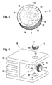
- the LED module 1 shown in Figures 1 to 4 is intended for installation in a not shown in the figures lighting unit. It comprises a cylindrical housing 2 made of aluminum, which in each case has a recess 3 at its two end faces and is thus designed to be open. Between the two recesses 3 is a disc-shaped base 4, which is integrally connected to the sleeve-shaped wall 5 of the housing 2.
- a total of four LED components 6 are added, which are each designed here as a surface-mounted LED chips.
- the individual LED chips 6 are arranged in a 2x2 array on a carrier board 7, which is mounted directly on the base 4. In this way, the LED chips 6 are thermally conductive connected via the carrier board 7 and the base 4 with the wall 5 of the module housing 2.
- the module housing 2 in this case represents a thermal contact element, via which the heat loss of the LED components 6 can be dissipated to the LED module 1 receiving luminous unit or to a heat sink 8 of a lighting unit.
- a circuit board 9 is accommodated, which forms a control unit 10 for the LED chips 6 with a drive circuit applied thereto.
- the control unit 10 is connected to the LED chips 6 via two contact pins 11 that are led through the base 4 in an insulating manner.
- the front end surfaces of the contact pins 11 are connected by bonding wires 12 to the carrier board 7 and with the LED chips 6 mounted thereon.
- the rear end regions of the contact pins 11 each contact a connection socket of the control unit 10 embedded in the printed circuit board 9.
- connection means 13 may be provided, such as connector or pins.
- a plastic primary optics 14 can be glued over the LED chips 6 and / or inserted into the corresponding recess 3, in particular clipped, as shown in Figure 5.
- the four LED chips 6 are arranged in a row next to one another on the carrier board 7. Basically, any number of LED chips 6 can be provided in any arrangement in the LED module 1, depending on the purpose.
- the back of the housing 2 can be completed by a suitable cover.
- a pre-assembled LED module 1 is obtained, in which a control unit 10 for driving the LED components 6 is already integrated.
- the control unit can also be arranged at other locations of the LED module 1, for example on the rear side and / or the front side of the carrier board 7 of the LED chips 6.
- the pre-assembled LED modules1 are later particularly quickly and easily inserted into suitable recesses 15 of a heat sink 8 of a lighting unit.
- the LED chips 6 can be soldered onto a carrier board 7 in the form of a driving silicon IC.
- the drive itself serves as a carrier for the LED chips.
- the integrated control can also be carried out in silicon carbide, which is characterized by good thermal properties. Such an integration would be particularly advantageous because some LED manufacturers silicon carbide is used as a substrate for the LEDs.
- the monolithic semiconductor lighting unit can be equipped by this chip-on-chip solution directly with an example. Phosphorus-active lighting part and an integrated control part, in which a drive by integrated circuits, sensors and / or other switching logic is already integrated.
- the number of steps required to produce an LED module can be reduced.
- an integrated drive for example in the form of an ASIC, a plurality of possibly different LED chips can also be arranged on a carrier and driven at the same time.
- the LED modules 1 preferably have on their housing 2 an outside knurling 16, via which they are positively and non-positively pressed into the recesses 15 of the heat sink 8. At the same time a particularly simple, yet highly accurate optical alignment of the individual LED modules 1 to each other is achieved, so that a subsequent adjustment of individual LEDs for the desired focusing of the lighting unit during assembly is not required.
- the LED modules 1 can be pressed directly into their predetermined by the recesses 15 positionally accurate alignment in the heat sink 8.
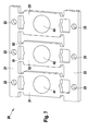
- the heat sink 8 shown in FIG. 6 has three recesses 15 in order to be able to record a total of three prefabricated LED modules 1 according to the invention, each with an integrated control unit.
- the heat sink 8 which also consists of aluminum, provided with cooling fins 17, via which the waste heat can be dissipated to the environment. Since the heat sink 8 is made of aluminum here as well as the housing 2 of the LED modules 1, not only results in a particularly good heat transfer due to the identical thermal expansion coefficient, but it is also a permanently secure interference fit between the module housings 2 and the heat sink 8 guaranteed ,
- the number and arrangement of the holes or recesses 15 as well as the shape of the heat sink 8 can be varied depending on the requirements of the associated lighting unit requirements.
- any orientation of the bores or recesses 15 in three-dimensional space is possible with a three-dimensional heat sink 8.
- the heat sink 8 may also be designed for a motor vehicle headlight.
- the recesses 15 are preferably introduced in a corresponding processing center in only a single clamping.
- FIG. 7 shows a metallic carrier strip, a so-called lead frame 20, to which a plurality of LED modules 1 can be attached.
- the carrier strip 20 is preferably made of copper or a copper alloy.
- the carrier strip 20 has a first mounting web 21 and a second mounting web 22, wherein the two mounting webs 21, 22 form parallel webs, in each of the mounting holes 23 are introduced.
- the carrier strip 20 can be mounted in a housing and optionally connected to further cooling elements.
- Support members 31, 32 and 33 which in the embodiment shown here form an approximate rectangular, planar surface, are held by thin support arms between the two webs 21, 22.
- each mounting surfaces 41, 42, 43 are sketched, where the respective LED modules 1, for example by gluing or can be applied by soldering.
- the module housing 2 preferably contacts the surface of the respective associated carrier element.
- the mounting webs 21, 22 are each connected only via thin connecting webs with the carriers 31, 32, 33. In FIG. 7, for reasons of clarity of the drawing, only two connecting webs 51, 52 are provided with a reference numeral. By means of the openings formed by the thin design of the connecting webs 51, the carriers 31, 32 can be cooled with air guided past them.
- connection webs in particular in an embodiment of a material with good heat conduction, that over the connecting webs 51, 52 heat to the mounting webs 21, 22 is led away for further dissipation.
- the attachment of the LED modules on the surface of the carrier 31, 32, 33 can be done by means known from the processing of power semiconductors manufacturing processes.
Applications Claiming Priority (2)
| Application Number | Priority Date | Filing Date | Title |
|---|---|---|---|
| DE102006054180 | 2006-11-16 | ||
| DE102007024390A DE102007024390A1 (de) | 2006-11-16 | 2007-05-25 | LED-Modul mit integrierter Ansteuerung |
Publications (2)
| Publication Number | Publication Date |
|---|---|
| EP1923626A1 true EP1923626A1 (fr) | 2008-05-21 |
| EP1923626B1 EP1923626B1 (fr) | 2009-08-19 |
Family
ID=39027610
Family Applications (2)
| Application Number | Title | Priority Date | Filing Date |
|---|---|---|---|
| EP07118261A Expired - Fee Related EP1923626B1 (fr) | 2006-11-16 | 2007-10-11 | Module DEL avec commande intégrée |
| EP07118265A Not-in-force EP1923627B1 (fr) | 2006-11-16 | 2007-10-11 | Commande intégrée d'agencements de DEL |
Family Applications After (1)
| Application Number | Title | Priority Date | Filing Date |
|---|---|---|---|
| EP07118265A Not-in-force EP1923627B1 (fr) | 2006-11-16 | 2007-10-11 | Commande intégrée d'agencements de DEL |
Country Status (4)
| Country | Link |
|---|---|
| EP (2) | EP1923626B1 (fr) |
| AT (1) | ATE440250T1 (fr) |
| DE (3) | DE102007024390A1 (fr) |
| ES (2) | ES2329522T3 (fr) |
Cited By (8)
| Publication number | Priority date | Publication date | Assignee | Title |
|---|---|---|---|---|
| WO2010060420A1 (fr) * | 2008-11-28 | 2010-06-03 | Osram Opto Semiconductors Gmbh | Lampe optoélectronique |
| WO2010145925A1 (fr) * | 2009-06-15 | 2010-12-23 | Osram Gesellschaft mit beschränkter Haftung | Corps de refroidissement pour éléments luminescents à semi-conducteur |
| WO2011139548A3 (fr) * | 2010-05-04 | 2012-03-22 | Xicato, Inc. | Connexion électrique souple d'un dispositif d'éclairage à del à un luminaire |
| WO2013120962A1 (fr) * | 2012-02-16 | 2013-08-22 | Osram Gmbh | Module d'éclairage |
| WO2016124776A1 (fr) * | 2015-02-05 | 2016-08-11 | Valeo Vision | Dispositif de connexion d'une source lumineuse à un dispositif d'alimentation électrique |
| EP2623851A4 (fr) * | 2010-09-28 | 2018-04-18 | Koito Manufacturing Co., Ltd. | Module de circuit, module émetteur de lumière et lampe de véhicule |
| EP3382269A1 (fr) * | 2017-03-30 | 2018-10-03 | Valeo North America, Inc. | Dissipateur thermique replié avec protection de connexion électrique |
| EP3495720A1 (fr) * | 2017-12-07 | 2019-06-12 | Valeo Vision | Module lumineux pour vehicule automobile |
Families Citing this family (9)
| Publication number | Priority date | Publication date | Assignee | Title |
|---|---|---|---|---|
| DE102009054620A1 (de) | 2009-12-14 | 2011-06-16 | Robert Bosch Gmbh | Lichtmodul zum Einbau in ein Leuchtaggregat |
| DE102009060790A1 (de) | 2009-12-22 | 2011-06-30 | Automotive Lighting Reutlingen GmbH, 72762 | Lichtmodul für eine Beleuchtungseinrichtung eines Kraftfahrzeugs sowie Beleuchtungseinrichtung eines Kraftfahrzeugs mit einem solchen Lichtmodul |
| DE102010003364A1 (de) * | 2010-03-26 | 2011-11-17 | Osram Gesellschaft mit beschränkter Haftung | Leuchtvorrichtung und Fahrzeugscheinwerfer mit einer solchen Leuchtvorrichtung |
| DE102010029227A1 (de) * | 2010-05-21 | 2011-11-24 | Osram Gesellschaft mit beschränkter Haftung | Leuchtvorrichtung |
| DE102010031055B4 (de) | 2010-07-07 | 2023-02-23 | Robert Bosch Gmbh | Sensormodul und Verfahren zum Herstellen eines Sensormoduls |
| DE102011005047B3 (de) * | 2011-03-03 | 2012-09-06 | Osram Ag | Leuchtvorrichtung |
| DE102011076122A1 (de) * | 2011-05-19 | 2012-11-22 | Olympus Winter & Ibe Gmbh | Dampfsterilisierbare Lichtquelle |
| DE102014109292A1 (de) | 2014-07-03 | 2016-01-07 | Hellmann Components Ug | Einbauleuchtmelder |
| US10180248B2 (en) | 2015-09-02 | 2019-01-15 | ProPhotonix Limited | LED lamp with sensing capabilities |
Citations (6)
| Publication number | Priority date | Publication date | Assignee | Title |
|---|---|---|---|---|
| DE19528459A1 (de) * | 1995-08-03 | 1997-02-13 | Garufo Gmbh | Leuchtaggregat |
| WO2001014789A1 (fr) * | 1999-08-23 | 2001-03-01 | Dialight Corporation | Feu d'obstacle a led |
| WO2002097884A1 (fr) | 2001-05-26 | 2002-12-05 | Gelcore, Llc | Module de del de grande puissance pour un eclairage |
| WO2004079256A1 (fr) | 2003-03-06 | 2004-09-16 | Space Cannon Vh S.P.A. | Projecteur a diodes electroluminescentes |
| US20060007013A1 (en) | 2004-07-08 | 2006-01-12 | Honeywell International Inc. | White LED anti-collision light utilizing light-emitting diode (LED) technology |
| US20060012986A1 (en) * | 2004-07-19 | 2006-01-19 | Joseph Mazzochette | LED array package with internal feedback and control |
Family Cites Families (2)
| Publication number | Priority date | Publication date | Assignee | Title |
|---|---|---|---|---|
| JP3201791B2 (ja) * | 1991-10-22 | 2001-08-27 | 株式会社リコー | 光出力デバイスの実装構造およびその実装方法 |
| US20020154346A1 (en) | 2001-04-18 | 2002-10-24 | Umax Data Sytems Inc. | Scanning head module |
-
2007
- 2007-05-25 DE DE102007024390A patent/DE102007024390A1/de not_active Withdrawn
- 2007-10-11 EP EP07118261A patent/EP1923626B1/fr not_active Expired - Fee Related
- 2007-10-11 EP EP07118265A patent/EP1923627B1/fr not_active Not-in-force
- 2007-10-11 DE DE502007001339T patent/DE502007001339D1/de active Active
- 2007-10-11 ES ES07118265T patent/ES2329522T3/es active Active
- 2007-10-11 ES ES07118261T patent/ES2330386T3/es active Active
- 2007-10-11 AT AT07118265T patent/ATE440250T1/de not_active IP Right Cessation
- 2007-10-11 DE DE502007001338T patent/DE502007001338D1/de active Active
Patent Citations (6)
| Publication number | Priority date | Publication date | Assignee | Title |
|---|---|---|---|---|
| DE19528459A1 (de) * | 1995-08-03 | 1997-02-13 | Garufo Gmbh | Leuchtaggregat |
| WO2001014789A1 (fr) * | 1999-08-23 | 2001-03-01 | Dialight Corporation | Feu d'obstacle a led |
| WO2002097884A1 (fr) | 2001-05-26 | 2002-12-05 | Gelcore, Llc | Module de del de grande puissance pour un eclairage |
| WO2004079256A1 (fr) | 2003-03-06 | 2004-09-16 | Space Cannon Vh S.P.A. | Projecteur a diodes electroluminescentes |
| US20060007013A1 (en) | 2004-07-08 | 2006-01-12 | Honeywell International Inc. | White LED anti-collision light utilizing light-emitting diode (LED) technology |
| US20060012986A1 (en) * | 2004-07-19 | 2006-01-19 | Joseph Mazzochette | LED array package with internal feedback and control |
Cited By (24)
| Publication number | Priority date | Publication date | Assignee | Title |
|---|---|---|---|---|
| WO2010060420A1 (fr) * | 2008-11-28 | 2010-06-03 | Osram Opto Semiconductors Gmbh | Lampe optoélectronique |
| WO2010145925A1 (fr) * | 2009-06-15 | 2010-12-23 | Osram Gesellschaft mit beschränkter Haftung | Corps de refroidissement pour éléments luminescents à semi-conducteur |
| US9797587B2 (en) | 2010-05-04 | 2017-10-24 | Xicato, Inc. | Flexible electrical connection of an LED-based illumination device to a light fixture |
| WO2011139548A3 (fr) * | 2010-05-04 | 2012-03-22 | Xicato, Inc. | Connexion électrique souple d'un dispositif d'éclairage à del à un luminaire |
| US8237381B2 (en) | 2010-05-04 | 2012-08-07 | Xicato, Inc. | Flexible electrical connection of an LED-based illumination device to a light fixture |
| US8517562B2 (en) | 2010-05-04 | 2013-08-27 | Xicato, Inc. | Flexible electrical connection of an LED-based illumination device to a light fixture |
| US9360168B2 (en) | 2010-05-04 | 2016-06-07 | Xicato, Inc. | Flexible electrical connection of an LED-based illumination device to a light fixture |
| EP2623851A4 (fr) * | 2010-09-28 | 2018-04-18 | Koito Manufacturing Co., Ltd. | Module de circuit, module émetteur de lumière et lampe de véhicule |
| WO2013120962A1 (fr) * | 2012-02-16 | 2013-08-22 | Osram Gmbh | Module d'éclairage |
| CN104126095A (zh) * | 2012-02-16 | 2014-10-29 | 欧司朗股份有限公司 | 发光模块 |
| US9279574B2 (en) | 2012-02-16 | 2016-03-08 | Osram Gmbh | Lighting module |
| CN107428284A (zh) * | 2015-02-05 | 2017-12-01 | 法雷奥照明公司 | 用于将光源连接到电源装置的装置 |
| FR3032561A1 (fr) * | 2015-02-05 | 2016-08-12 | Valeo Vision | Dispositif de connexion d’une source lumineuse a un dispositif d’alimentation electrique |
| US20180023792A1 (en) * | 2015-02-05 | 2018-01-25 | Valeo Vision | Device for connecting a light source to an electrical power supply device |
| WO2016124776A1 (fr) * | 2015-02-05 | 2016-08-11 | Valeo Vision | Dispositif de connexion d'une source lumineuse à un dispositif d'alimentation électrique |
| US10337713B2 (en) | 2015-02-05 | 2019-07-02 | Valeo Vision | Device for connecting a light source to an electrical power supply device |
| CN112874430A (zh) * | 2015-02-05 | 2021-06-01 | 法雷奥照明公司 | 用于将光源连接到电源装置的装置 |
| EP3382269A1 (fr) * | 2017-03-30 | 2018-10-03 | Valeo North America, Inc. | Dissipateur thermique replié avec protection de connexion électrique |
| EP3495720A1 (fr) * | 2017-12-07 | 2019-06-12 | Valeo Vision | Module lumineux pour vehicule automobile |
| FR3074881A1 (fr) * | 2017-12-07 | 2019-06-14 | Valeo Vision | Module lumineux pour vehicule automobile |
| CN109973914A (zh) * | 2017-12-07 | 2019-07-05 | 法雷奥照明公司 | 用于机动车辆的灯模块 |
| US10648655B2 (en) | 2017-12-07 | 2020-05-12 | Valeo Vision | Light module for a vehicle with a heat sink with void housing a driving device arranged on an electronic support |
| US10890317B2 (en) | 2017-12-07 | 2021-01-12 | Valeo Vision | Module for motor vehicle comprising an optical element fixed to a heatsink with posts and a light source fixed to a fixing zone of a heatsink |
| US11313549B2 (en) | 2017-12-07 | 2022-04-26 | Valeo Vision | Module for motor vehicle comprising an optical element fixed to a heatsink with posts and a light source fixed to a fixing zone of a heatsink |
Also Published As
| Publication number | Publication date |
|---|---|
| DE502007001339D1 (de) | 2009-10-01 |
| ES2329522T3 (es) | 2009-11-26 |
| EP1923627A1 (fr) | 2008-05-21 |
| EP1923627B1 (fr) | 2009-08-19 |
| ATE440250T1 (de) | 2009-09-15 |
| EP1923626B1 (fr) | 2009-08-19 |
| DE502007001338D1 (de) | 2009-10-01 |
| ES2330386T3 (es) | 2009-12-09 |
| DE102007024390A1 (de) | 2008-05-21 |
Similar Documents
| Publication | Publication Date | Title |
|---|---|---|
| EP1923626B1 (fr) | Module DEL avec commande intégrée | |
| DE102007002839A1 (de) | Leuchtaggregat mit mehreren LED-Bauelementen und Verfahren zu seiner Herstellung | |
| EP2317213B1 (fr) | Module de diode luminescente d'un dispositif d'éclairage de véhicule automobile et dispositif d'éclairage de véhicule automobile | |
| EP2095016B1 (fr) | Unité d'éclairage pour phare de véhicule, et phare de véhicule correspondant | |
| EP2142847B1 (fr) | Module d'éclairage à semiconducteurs | |
| EP1995514B1 (fr) | Unité d'éclairage | |
| EP2291594B1 (fr) | Unité d éclairage pour phare de véhicule et phare de véhicule | |
| EP1721102B1 (fr) | Lampe | |
| EP2198196B1 (fr) | Lampe | |
| DE102008016458A1 (de) | Leiterplatte | |
| DE102007044684B4 (de) | Kompakte Hochintensitäts LED basierte Lichtquelle und Verfahren zum Herstellen derselben | |
| DE202014002809U1 (de) | Beleuchtungseinrichtung | |
| WO2016162331A1 (fr) | Dispositif d'éclairage avec puces en semiconducteur sur un support et avec une lentille optique commune | |
| DE10110835A1 (de) | Beleuchtungsanordnung | |
| EP2096685A1 (fr) | Module à DEL doté de corps de refroidissement comprenant un moyen de montage | |
| DE102011076128A1 (de) | Trägersystem und Lichtmodul zur Befestigung daran | |
| WO2012126894A1 (fr) | Appareil d'éclairage | |
| DE102009054620A1 (de) | Lichtmodul zum Einbau in ein Leuchtaggregat | |
| EP1898144A2 (fr) | Agrégat lumineux doté de plusieurs composants DEL et son procédé de fabrication | |
| WO2013064405A1 (fr) | Dispositif d'éclairage comprenant des sources de lumière à semi-conducteur | |
| DE102004036931B4 (de) | Automobiler Scheinwerfer | |
| DE19928576A1 (de) | Oberflächenmontierbares LED-Bauelement mit verbesserter Wärmeabfuhr | |
| DE102012211143A1 (de) | Träger für elektrisches bauelement mit wärmeleitkörper | |
| EP2845235B1 (fr) | Ensemble del | |
| EP1890332A2 (fr) | Module d'éclairage et procédé destiné à la fabrication d'un module d'éclairage |
Legal Events
| Date | Code | Title | Description |
|---|---|---|---|
| PUAI | Public reference made under article 153(3) epc to a published international application that has entered the european phase |
Free format text: ORIGINAL CODE: 0009012 |
|
| AK | Designated contracting states |
Kind code of ref document: A1 Designated state(s): AT BE BG CH CY CZ DE DK EE ES FI FR GB GR HU IE IS IT LI LT LU LV MC MT NL PL PT RO SE SI SK TR |
|
| AX | Request for extension of the european patent |
Extension state: AL BA HR MK RS |
|
| 17P | Request for examination filed |
Effective date: 20081121 |
|
| 17Q | First examination report despatched |
Effective date: 20081217 |
|
| AKX | Designation fees paid |
Designated state(s): DE ES FR GB IT |
|
| GRAP | Despatch of communication of intention to grant a patent |
Free format text: ORIGINAL CODE: EPIDOSNIGR1 |
|
| GRAS | Grant fee paid |
Free format text: ORIGINAL CODE: EPIDOSNIGR3 |
|
| GRAA | (expected) grant |
Free format text: ORIGINAL CODE: 0009210 |
|
| AK | Designated contracting states |
Kind code of ref document: B1 Designated state(s): DE ES FR GB IT |
|
| REG | Reference to a national code |
Ref country code: GB Ref legal event code: FG4D Free format text: NOT ENGLISH |
|
| REF | Corresponds to: |
Ref document number: 502007001338 Country of ref document: DE Date of ref document: 20091001 Kind code of ref document: P |
|
| REG | Reference to a national code |
Ref country code: ES Ref legal event code: FG2A Ref document number: 2330386 Country of ref document: ES Kind code of ref document: T3 |
|
| PLBE | No opposition filed within time limit |
Free format text: ORIGINAL CODE: 0009261 |
|
| STAA | Information on the status of an ep patent application or granted ep patent |
Free format text: STATUS: NO OPPOSITION FILED WITHIN TIME LIMIT |
|
| 26N | No opposition filed |
Effective date: 20100520 |
|
| PG25 | Lapsed in a contracting state [announced via postgrant information from national office to epo] |
Ref country code: IT Free format text: LAPSE BECAUSE OF NON-PAYMENT OF DUE FEES Effective date: 20101011 |
|
| REG | Reference to a national code |
Ref country code: FR Ref legal event code: PLFP Year of fee payment: 9 |
|
| REG | Reference to a national code |
Ref country code: FR Ref legal event code: PLFP Year of fee payment: 10 |
|
| REG | Reference to a national code |
Ref country code: FR Ref legal event code: PLFP Year of fee payment: 11 |
|
| REG | Reference to a national code |
Ref country code: FR Ref legal event code: PLFP Year of fee payment: 12 |
|
| PGFP | Annual fee paid to national office [announced via postgrant information from national office to epo] |
Ref country code: DE Payment date: 20191212 Year of fee payment: 13 |
|
| PGFP | Annual fee paid to national office [announced via postgrant information from national office to epo] |
Ref country code: IT Payment date: 20191021 Year of fee payment: 13 Ref country code: FR Payment date: 20191022 Year of fee payment: 13 Ref country code: ES Payment date: 20191120 Year of fee payment: 13 |
|
| PGFP | Annual fee paid to national office [announced via postgrant information from national office to epo] |
Ref country code: GB Payment date: 20191023 Year of fee payment: 13 |
|
| REG | Reference to a national code |
Ref country code: DE Ref legal event code: R119 Ref document number: 502007001338 Country of ref document: DE |
|
| GBPC | Gb: european patent ceased through non-payment of renewal fee |
Effective date: 20201011 |
|
| PG25 | Lapsed in a contracting state [announced via postgrant information from national office to epo] |
Ref country code: FR Free format text: LAPSE BECAUSE OF NON-PAYMENT OF DUE FEES Effective date: 20201031 Ref country code: DE Free format text: LAPSE BECAUSE OF NON-PAYMENT OF DUE FEES Effective date: 20210501 |
|
| PG25 | Lapsed in a contracting state [announced via postgrant information from national office to epo] |
Ref country code: GB Free format text: LAPSE BECAUSE OF NON-PAYMENT OF DUE FEES Effective date: 20201011 |
|
| PG25 | Lapsed in a contracting state [announced via postgrant information from national office to epo] |
Ref country code: IT Free format text: LAPSE BECAUSE OF NON-PAYMENT OF DUE FEES Effective date: 20201011 |
|
| REG | Reference to a national code |
Ref country code: ES Ref legal event code: FD2A Effective date: 20220121 |
|
| PG25 | Lapsed in a contracting state [announced via postgrant information from national office to epo] |
Ref country code: ES Free format text: LAPSE BECAUSE OF NON-PAYMENT OF DUE FEES Effective date: 20201012 |