EP1923596A1 - Hydraulischer stossdämpfer - Google Patents
Hydraulischer stossdämpfer Download PDFInfo
- Publication number
- EP1923596A1 EP1923596A1 EP06797636A EP06797636A EP1923596A1 EP 1923596 A1 EP1923596 A1 EP 1923596A1 EP 06797636 A EP06797636 A EP 06797636A EP 06797636 A EP06797636 A EP 06797636A EP 1923596 A1 EP1923596 A1 EP 1923596A1
- Authority
- EP
- European Patent Office
- Prior art keywords
- chamber
- damping force
- piston
- force generating
- shock absorber
- Prior art date
- Legal status (The legal status is an assumption and is not a legal conclusion. Google has not performed a legal analysis and makes no representation as to the accuracy of the status listed.)
- Granted
Links
- 230000035939 shock Effects 0.000 title claims abstract description 143
- 239000006096 absorbing agent Substances 0.000 title claims abstract description 141
- 238000013016 damping Methods 0.000 claims abstract description 336
- 230000009471 action Effects 0.000 claims description 145
- 230000033228 biological regulation Effects 0.000 claims description 13
- 239000000725 suspension Substances 0.000 claims description 4
- 230000006835 compression Effects 0.000 description 57
- 238000007906 compression Methods 0.000 description 57
- 230000007423 decrease Effects 0.000 description 35
- 239000007789 gas Substances 0.000 description 32
- 230000000694 effects Effects 0.000 description 27
- 230000004044 response Effects 0.000 description 16
- 230000008859 change Effects 0.000 description 13
- 230000003247 decreasing effect Effects 0.000 description 5
- 239000012530 fluid Substances 0.000 description 4
- IJGRMHOSHXDMSA-UHFFFAOYSA-N Atomic nitrogen Chemical compound N#N IJGRMHOSHXDMSA-UHFFFAOYSA-N 0.000 description 3
- 230000008878 coupling Effects 0.000 description 3
- 238000010168 coupling process Methods 0.000 description 3
- 238000005859 coupling reaction Methods 0.000 description 3
- 229910001873 dinitrogen Inorganic materials 0.000 description 3
- 230000000977 initiatory effect Effects 0.000 description 3
- 125000006850 spacer group Chemical group 0.000 description 3
- 230000001276 controlling effect Effects 0.000 description 2
- 238000005461 lubrication Methods 0.000 description 2
- 230000000630 rising effect Effects 0.000 description 2
- 230000009286 beneficial effect Effects 0.000 description 1
- 230000006837 decompression Effects 0.000 description 1
- 230000012447 hatching Effects 0.000 description 1
- 239000000203 mixture Substances 0.000 description 1
- 230000001105 regulatory effect Effects 0.000 description 1
- 238000005096 rolling process Methods 0.000 description 1
Images


Classifications
-
- F—MECHANICAL ENGINEERING; LIGHTING; HEATING; WEAPONS; BLASTING
- F16—ENGINEERING ELEMENTS AND UNITS; GENERAL MEASURES FOR PRODUCING AND MAINTAINING EFFECTIVE FUNCTIONING OF MACHINES OR INSTALLATIONS; THERMAL INSULATION IN GENERAL
- F16F—SPRINGS; SHOCK-ABSORBERS; MEANS FOR DAMPING VIBRATION
- F16F9/00—Springs, vibration-dampers, shock-absorbers, or similarly-constructed movement-dampers using a fluid or the equivalent as damping medium
- F16F9/06—Springs, vibration-dampers, shock-absorbers, or similarly-constructed movement-dampers using a fluid or the equivalent as damping medium using both gas and liquid
- F16F9/064—Units characterised by the location or shape of the expansion chamber
- F16F9/065—Expansion chamber provided on the upper or lower end of a damper, separately there from or laterally on the damper
-
- F—MECHANICAL ENGINEERING; LIGHTING; HEATING; WEAPONS; BLASTING
- F16—ENGINEERING ELEMENTS AND UNITS; GENERAL MEASURES FOR PRODUCING AND MAINTAINING EFFECTIVE FUNCTIONING OF MACHINES OR INSTALLATIONS; THERMAL INSULATION IN GENERAL
- F16F—SPRINGS; SHOCK-ABSORBERS; MEANS FOR DAMPING VIBRATION
- F16F9/00—Springs, vibration-dampers, shock-absorbers, or similarly-constructed movement-dampers using a fluid or the equivalent as damping medium
- F16F9/32—Details
- F16F9/3207—Constructional features
- F16F9/3214—Constructional features of pistons
-
- F—MECHANICAL ENGINEERING; LIGHTING; HEATING; WEAPONS; BLASTING
- F16—ENGINEERING ELEMENTS AND UNITS; GENERAL MEASURES FOR PRODUCING AND MAINTAINING EFFECTIVE FUNCTIONING OF MACHINES OR INSTALLATIONS; THERMAL INSULATION IN GENERAL
- F16F—SPRINGS; SHOCK-ABSORBERS; MEANS FOR DAMPING VIBRATION
- F16F9/00—Springs, vibration-dampers, shock-absorbers, or similarly-constructed movement-dampers using a fluid or the equivalent as damping medium
- F16F9/32—Details
- F16F9/34—Special valve constructions; Shape or construction of throttling passages
- F16F9/348—Throttling passages in the form of annular discs or other plate-like elements which may or may not have a spring action, operating in opposite directions or singly, e.g. annular discs positioned on top of the valve or piston body
-
- F—MECHANICAL ENGINEERING; LIGHTING; HEATING; WEAPONS; BLASTING
- F16—ENGINEERING ELEMENTS AND UNITS; GENERAL MEASURES FOR PRODUCING AND MAINTAINING EFFECTIVE FUNCTIONING OF MACHINES OR INSTALLATIONS; THERMAL INSULATION IN GENERAL
- F16F—SPRINGS; SHOCK-ABSORBERS; MEANS FOR DAMPING VIBRATION
- F16F9/00—Springs, vibration-dampers, shock-absorbers, or similarly-constructed movement-dampers using a fluid or the equivalent as damping medium
- F16F9/32—Details
- F16F9/44—Means on or in the damper for manual or non-automatic adjustment; such means combined with temperature correction
- F16F9/46—Means on or in the damper for manual or non-automatic adjustment; such means combined with temperature correction allowing control from a distance, i.e. location of means for control input being remote from site of valves, e.g. on damper external wall
- F16F9/466—Throttling control, i.e. regulation of flow passage geometry
-
- F—MECHANICAL ENGINEERING; LIGHTING; HEATING; WEAPONS; BLASTING
- F16—ENGINEERING ELEMENTS AND UNITS; GENERAL MEASURES FOR PRODUCING AND MAINTAINING EFFECTIVE FUNCTIONING OF MACHINES OR INSTALLATIONS; THERMAL INSULATION IN GENERAL
- F16F—SPRINGS; SHOCK-ABSORBERS; MEANS FOR DAMPING VIBRATION
- F16F2230/00—Purpose; Design features
- F16F2230/42—Multiple pistons
Definitions
- the present invention relates to a hydraulic shock absorber in which the damping force characteristics using a bulk modulus of a hydraulic fluid more effectively can be obtained when the moving speed of a piston rod in relation to a cylinder tube is slow as in the initial stage of compression action and extension action, in a case that the hydraulic shock absorber repeats the compression action and the extension action by a first and second input forces applied from outside.
- the hydraulic shock absorber of a conventional type is shown in the Patent Document 1.
- the hydraulic shock absorber is inserted in the cylinder tube slidably in the axial direction, and the hydraulic shock absorber includes: first and second pistons for dividing the inside of the cylinder tube to a first chamber, an intermediate chamber, and a second chamber from one end to another end in this order; and a piston rod in which one end is connected to the first and the second pistons, and another end protrudes out of the cylinder tube from another end of the cylinder tube.
- the shock absorber also includes: a first damping force generating device for absorbing a first input force, by flowing oil from the first chamber through the first piston to the intermediate chamber, when the first input force is applied from outside in order to insert the piston rod deeper into the cylinder tube; and a second damping force generating device for absorbing the first input force by flowing oil from the intermediate chamber through the second piston to the second chamber, when the first input force is applied.
- a hydraulic fluid used in the shock absorber is a compressible fluid with a characteristic performing a volume change against pressurerization or decompression (hereinafter, this is simply referred to as "bulk modulus") .
- a capacity of the second chamber alone is small, so if compared with the imaginary chamber that has same pressure value and larger capacity than the second chamber, the volume change amount of the oil in the second chamber according to the "bulk modulus" is smaller (harder) than that of the imaginary chamber.
- the shock absorber when the shock absorber is applied with a second input force from outside, then the first and the second pistons, and piston rods perform an action to exit from the cylinder tube, that is, when the shock absorber is in the extension action, the second chamber performs compression at the initial stage, and its hydraulic pressure becomes higher than that of the intermediate chamber.
- the present invention is made in view of above-mentioned circumstances.
- the object of the present invention is to provide a hydraulic shock absorber in which the "response" is restrained to be low when the moving speed of the piston rod in relation to the cylinder tube is slow, while the “response” is set high when the first and the second input forces are large and the moving speed is fast, in a case that at the initial stage in the compression and the extension actions of hydraulic shock absorber performs when the first and the second input forces are applied from outside.
- Another object of the present invention is to provide a soft driving feel to a vehicle by equipping the shock absorber to a vehicle, and at the same time to provide further improved driving feel and driving safety by absorbing shocks without delay when the large first and second input forces are applied.
- another cylinder tube may be disposed as a separate unit from the cylinder tube, and the free piston may be inserted in the cylinder tube slidably in the axial direction, and one of two chambers in the cylinder tube divided by this free piston may be filled with the oil then set as an oil storage chamber that is in communication with the first chamber, while the other chamber may be set as the gas enclosure chamber filled with high pressure gas.
- the oil in the first chamber flows from this first chamber through the pressure side first damping force generating device in the first chamber to the intermediate chamber. Also, the oil in the intermediate chamber flows from the intermediate chamber through the pressure side second damping force generating device in the second piston to the second chamber. In this way, the pressure side first and second damping force generating devices try to generate the damping force concurrently, by flowing the oil in these.
- the capacity of the second chamber alone is small, so the volume change amount by the "bulk module” of the oil in this second chamber is small (hard) . Therefore, according to the entering action of the second piston, the decrease speed of the hydraulic pressure in the second chamber becomes faster, then the "response" in the pressure side second damping force generating device becomes higher.
- the damping force of the extension side first damping force generating device is larger than that of the extension side second damping force generating device. Therefore, like at the initial stage in the extension action of the shock absorber, when the moving speed is slow, among the extension side first and second damping force generating devices, the extension side first damping force generating device generates the damping force dominantly, and the extension side second damping force generating device barely generates the damping force. Therefore, the first chamber and the intermediate chamber, at back in the proceeding direction of the first and the second pistons working with the piston rod, decreases its pressure concurrently. These pressure decreases are generally same, so the intermediate chamber and the second chamber function like a united single chamber.
- the pressure side and the extension side first damping force generating devices may include pressure side and extension side first valves for flowing oil in order to pass through the first piston by the first hydraulic pressure difference between the first chamber and the intermediate chamber, when the first and the second input forces are applied, and may include a first orifice that passes through the first piston.
- the pressure side and the extension side second damping force generating devices may include pressure side and extension side second valves for flowing oil to pass through the second piston by the second hydraulic pressure difference between the intermediate chamber and the second chamber when the first and the second input forces are applied, and may include a second orifice that passes through the second piston.
- the open valve pressure characteristics of the pressure side and the extension side first valves may be set weaker than that of the pressure side and the extension side second valves.
- the cross section of the first orifice may be smaller than that of the second orifice.
- the second chamber is expanded by the entering action of the first and the second pistons to the cylinder tube, and its hydraulic pressure decreases.
- generally same amount of oil flows from the first chamber and intermediate chamber through the first orifice in the first piston and the second orifice in the second piston toward the second chamber. Therefore the hydraulic pressure in the intermediate chamber decreases in relation to the hydraulic pressure in the first chamber, also, the hydraulic pressure in the second chamber decreases in relation to the hydraulic pressure in the intermediate chamber.
- the cross section of the second orifice is more than ten times of the cross section of the first orifice, the cross section of the second orifice becomes oversized. Then, the expected damping force is difficult to obtain even if the oil flows in the second orifice 44. Therefore, it is difficult to obtain the expected damping force especially when the moving speed is fast.
- kinetic viscosity of the oil may be set four to ten centistokes (cSt) at 40°C.
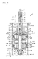
- the hydraulic shock absorber 1 includes a single cylinder type cylinder tube 8 that has a shaft center toward the longitudinal direction.
- This cylinder tube 8 includes a tube body 9 located above the shaft center 7, a cap 11 for closing the opening of the lower end of the tube body 9 which is one end 10 of the cylinder tube 8, and a head cover 13 for closing the opening of the upper end of the tube body 9 which is another end 12 of the cylinder tube 8.
- the one end 10 of the cylinder tube 8 is pivot supported by a pivot shaft 14 in relation to the respective vehicle wheel side 4.
- the pressure side first damping force generating device 34 includes a pressure side first valve 36.
- a plurality of valve holes 37 that pass through the first piston 17 are formed on the first piston 17 in the circumferential direction at the certain spacing. These valve holes 37 communicate the first chamber 19 and the intermediate chamber 20, respectively.
- the first valve 36 includes a pressure side leaf valve body 38 that can open and close and resiliently close the exit side of the valve hole 37.
- a notch 37a is formed on the entrance side of the valve hole 37.
- the leaf valve body 38 is constituted with a plurality (two pieces) of disc form leaf that has different diameters with one another. The leaf valve body 38 is supported to the piston rod 23 between the first piston 17 and the washer 25 of the coupling tool 24 through a leaf sheet 40.
- the gas enclosure chamber 56 filled with gas is connected to the first chamber 19 through the free piston 53.
- the hydraulic pressure in the first chamber 19 is restrained from rising by the motion of the free piston 53 and the compression of the gas in the gas enclosure chamber 56. Therefore, the oil 31 is prevented from immediately flowing in the pressure side first damping force generating device 34 from the first chamber 19 toward the intermediate chamber 20 and the second chamber 21 by the hydraulic pressure P1 in the first chamber 19.
- the shock absorber1 when the shock absorber1 is applied with second input force A' that is an applying force of the spring 49 and performs the extension action C, the oil 31 in the second chamber 21 flows from the second chamber 21 through the extension side second damping force generating device 47 in the second piston 18 toward the intermediate chamber 20. Also, the oil 31 in the intermediate chamber 20 flows from the intermediate chamber 20 through the extension side first damping force generating device 46 in the first piston 17 toward the first chamber 19. In this way the extension side first and second damping force generating devices 46, 47 try to generate the damping force coordinately by flowing the oil 31 in these respectively.
- the second chamber 21 is compressed by the exit action of the first and the second pistons 17, 18 from the cylinder tube 8, and its hydraulic pressure P2 is increased.
- P2 hydraulic pressure
- the hydraulic pressure PN in the intermediate chamber 20 increases in relation to the hydraulic pressure P1 in the first chamber 19.
- the hydraulic pressure P2 increases in relation to the hydraulic pressure PN in the intermediate chamber 20.
- the capacity of the first chamber 19 and the intermediate chamber 20 together is larger than the capacity of each single chamber. Then the volume change amount by the "bulk modulus" of the oil 31 in the first chamber 19 and the intermediate chamber 20 is maintained large (soft) . Therefore, the increase speed of the hydraulic pressure PN, P2 in the intermediate chamber 20 and the second chamber 21 is kept small. Therefore, immediate flow of the oil 31 from the intermediate chamber 20 and the second chamber 21 through the extension side first damping force generating device 46 toward the first chamber 19 is prevented. That is, the "response" is kept low at the initial stage of the extension action C of the shock absorber 1, and the sudden regulation of the piston rod 23 exiting from the cylinder tube 8 is prevented.
- each cross sectional value of the first and the second orifices 39, 44 come closer to one another. Therefore, if the shock absorber 1 is in the compression action C or extension action C after applied with the first and the second input forces A, A' , the oil 31 flows in the pressure side first and second damping force generating devices 34, 35, or in the extension side first and second damping force generating devices 46, 47, at the generally same time, under the generally same condition, from the initial stage of the respective actions B, C, and then tend to generate the generally same damping force. Therefore, it is difficult for the pressure side first damping force generating device 34 to generate the damping force dominantly at the initial stage of the respective actions B, C, and the "action effect" is hard to obtain.
- the cross section of the second orifice 44 is more than ten times of the cross section of the first orifice 39, the cross section of the second orifice 44 becomes oversized. Then, the expected damping force becomes difficult to get even if the oil 31 flows in the second orifice 44. Therefore, it is even more difficult to get the expected damping force when the moving speed V is fast (VH in FIG. 3 ) .
- the shock absorber 1 when the shock absorber 1 is repeatedly used, the temperature of the oil 31 rises, and then the kinetic viscosity tends to decrease.
- the decrease width of the kinetic viscosity according to temperature is wider as the kinetic viscosity of the oil 31 is higher.
- the kinetic viscosity of the oil 31 at the temperature of 40°C is one-and-half cSt, however, the decrease width of the kinetic viscosity according to temperature rising of the oil 31 becomes wider when this type of oil 31 is used. Then it is difficult to finely obtain the expected damping force to the shock absorber 1.
- wider parts are subject to an effect (resistance) of the viscosity of the oil 31 as for the shock absorber 1 using a plurality of pistons. In order to refrain the effect as much as possible, it is advantageous to use the mixture with the low viscosity oil 31 lower than the 10 centistokes.
- the shock absorber 1 may be disposed upside down or horizontally or obliquely.
- the flow resistance (pressure loss) of the oil 31 in the first orifice 39 may be set higher than that of the second orifice 44, by setting the cross section of the first and the second orifices 39,44 are same each other, or by setting the length of the first orifice 39 longer than that of the second orifice 44.
- the first and the second orifices 39, 44 may be formed by a plurality of passing holes. The diameter (cross section) of these passing holes may be same each other, and the number of passing holes in the second orifice 44 are more than those of the first orifice 39.
- the intermediate damping force generating device opens the valve according to the value between the first hydraulic pressure difference (P1-PN) and the second hydraulic pressure difference (PN-P2), and flows the oil 31 so as to passing through the intermediate piston 60.
- the cross section of the intermediate damping force generating device is a value between the cross sections of the respective first and second orifices.
- the accumulator 51 is formed in the cylinder tube 8 as a single unit. Specifically, the free piston 53 is inserted to the first chamber 19 in the way the free piston 53 can slide in the axial direction. The first chamber 19 is divided to two chambers by the free piston 53. The high-pressure nitrogen gas is enclosed to the opposite chamber to the first piston 17 as reference to the free piston 53.
- the shock absorber 1 can be made compactly according to this embodiment.
- the operation bolt 68 is inserted from another end (upper end) of the through-hole 63 and screwed to the piston rod 23.
- the needle valve 69 is attached as a single unit to the entering end of the operation bolt 68.
- the needle valve 69 faces against the second orifice 44.
- the needle valve 69 moves coordinately, so that the practical cross sectional value of the second orifice 44 may be changed.
- the needle valve 69 may be fixed to the piston rod 23 with this operation bolt 68 at the desired turning position.
- a damping force characteristic of the second orifice 44 may be changed to various values, between the intermediate to fast range in the moving speed V, and then may obtain the required characteristic, by controlling the regulation device 62.
- the cross section of the first orifice 39 in the pressure side and the extension side first damping force generating devices 34, 46 are fixed and maintained in the certain value regardless of the control on the regulation device. Therefore, if the shock absorber is equipped to the vehicle 2, a desired driving feel can be obtained, while maintaining the "action effect".
- FIG. 7 shows the shock absorber 1 in the compression action B.
- An outer diameter D1 of a part of the piston rod 23 connected to the first piston 17 is smaller than an outer diameter D2 of another part of the piston rod 23 connected to the second piston 18.
- Another end side 27 of the piston rod 23 is bigger than the outer diameter D2. Therefore, at least two step-difference-surfaces 28 are formed in the piston rod 23.
- the first and the second pistons 17, 18 are fastened individually by a fastening tool 29 to the each step-difference-surface 28.
- the first and the second pistons 17, 18 are respectively connected to the piston rod 23 rigidly.
- a passage 74 communicates the first chambers 19 of the shock absorber 1 to each other through a narrow section 73.
- the narrow section 73 is disposed in another free piston 72, and includes a pair of valves 75 that has same configuration and action as the first valve 36. These valves 75 accept the reverse flow of the oil 31 to each other.
- one of the shock absorbers 1 performs compression action B by the first input force A.
- the oil 31 in the first chamber 19 in the left side shock absorber 1 flows into the underside chamber of the free piston 72 among the oil storage chamber 54 in the accumulator 51 in the intermediate unit 50.
- another free piston 72 moves downward in reference to the cylinder tube 52 accompanied by the free piston 53, and the capacity of the upper chamber in another free piston 72.
- the oil 31 in the first chamber 19 in the other (right side) shock absorber 1 between both shock absorbers 1 is drawn into the chamber above another free piston 72, and accordingly the right side shock absorber 1 performs the compression action B.
- the both shock absorbers 1 perform the same action at the same time, so the vehicle 2 is protected against rolling or pitting.
- the bulk modulus of the oil 31 in the intermediate chamber 20 and the second chamber 21 of the shock absorber 1 is regulated to be low, due to the configuration of each embodiment according to each claim in the present document. Therefore, the precision for an amount of oil 31 drawing in or out in reference to the intermediate unit 50 is improved. Also the precision for the "action effect" is improved.
Landscapes
- Engineering & Computer Science (AREA)
- General Engineering & Computer Science (AREA)
- Mechanical Engineering (AREA)
- Fluid-Damping Devices (AREA)
Applications Claiming Priority (2)
| Application Number | Priority Date | Filing Date | Title |
|---|---|---|---|
| JP2005262224A JP4753238B2 (ja) | 2005-09-09 | 2005-09-09 | 油圧緩衝器 |
| PCT/JP2006/317776 WO2007029787A1 (ja) | 2005-09-09 | 2006-09-07 | 油圧緩衝器 |
Publications (3)
| Publication Number | Publication Date |
|---|---|
| EP1923596A1 true EP1923596A1 (de) | 2008-05-21 |
| EP1923596A4 EP1923596A4 (de) | 2011-12-21 |
| EP1923596B1 EP1923596B1 (de) | 2012-12-26 |
Family
ID=37835902
Family Applications (1)
| Application Number | Title | Priority Date | Filing Date |
|---|---|---|---|
| EP06797636A Active EP1923596B1 (de) | 2005-09-09 | 2006-09-07 | Hydraulischer stossdämpfer |
Country Status (4)
| Country | Link |
|---|---|
| US (1) | US8381887B2 (de) |
| EP (1) | EP1923596B1 (de) |
| JP (1) | JP4753238B2 (de) |
| WO (1) | WO2007029787A1 (de) |
Cited By (4)
| Publication number | Priority date | Publication date | Assignee | Title |
|---|---|---|---|---|
| EP2249057A1 (de) * | 2009-05-06 | 2010-11-10 | HEMSCHEIDT FAHRWERKTECHNIK GmbH & Co. KG | Dämpfungseinrichtung für Radfahrzeuge |
| EP2405154A1 (de) | 2010-07-05 | 2012-01-11 | HEMSCHEIDT FAHRWERKTECHNIK GmbH & Co. KG | Dämpfungseinrichtung für Radfahrzeuge |
| ITMI20111890A1 (it) * | 2011-10-18 | 2013-04-19 | Caimi Export Spa | Ammortizzatore |
| WO2019092480A1 (en) * | 2017-11-10 | 2019-05-16 | Maranini Simone | Shock absorbing system of a vehicle |
Families Citing this family (19)
| Publication number | Priority date | Publication date | Assignee | Title |
|---|---|---|---|---|
| JP4898512B2 (ja) * | 2007-03-23 | 2012-03-14 | 株式会社ショーワ | 減衰力発生装置 |
| JP4919045B2 (ja) * | 2007-04-19 | 2012-04-18 | 日立オートモティブシステムズ株式会社 | 減衰力調整式流体圧緩衝器 |
| SE531694C2 (sv) * | 2007-12-19 | 2009-07-07 | Oehlins Racing Ab | Stötdämpare med dubbelkolv |
| JP5248852B2 (ja) * | 2007-12-27 | 2013-07-31 | ヤマハ発動機株式会社 | 車体用振動減衰装置 |
| US8297418B2 (en) * | 2008-06-05 | 2012-10-30 | Tenneco Automotive Operating Company Inc. | Nested check high speed valve |
| TW201028329A (en) * | 2009-01-19 | 2010-08-01 | Y S S Thailand Co Ltd | Advanced triple piston damper |
| DE102011012730B4 (de) * | 2010-03-02 | 2021-04-29 | Hitachi Automotive Systems, Ltd. | Stoßdämpfer |
| CN103557260A (zh) * | 2013-09-30 | 2014-02-05 | 太仓康茂电子有限公司 | 一种油气弹簧 |
| JP2015129552A (ja) * | 2014-01-07 | 2015-07-16 | 株式会社ショーワ | 圧力緩衝装置 |
| JP6259676B2 (ja) * | 2014-02-13 | 2018-01-10 | 株式会社ショーワ | 圧力緩衝装置 |
| JP5620596B1 (ja) * | 2014-02-19 | 2014-11-05 | 千博産業株式会社 | 構造物の制振装置 |
| EP2913460B1 (de) | 2014-02-19 | 2017-08-23 | Chihiro Sangyo Co., Ltd. | Dämpfungsvorrichtung für ein Gebäude |
| CN107208726B (zh) * | 2015-02-03 | 2019-10-01 | 天纳克汽车营运公司 | 用于减振器的次级阻尼组件 |
| WO2016127076A1 (en) * | 2015-02-06 | 2016-08-11 | Tenneco Automotive Operating Company Inc. | Secondary dampening assembly for a shock absorber |
| DE102018217372B3 (de) * | 2018-10-11 | 2020-03-05 | Zf Friedrichshafen Ag | Dämpfervorrichtung sowie Fahrzeug mit der Dämpfervorrichtung |
| DE102018217371B3 (de) * | 2018-10-11 | 2020-01-23 | Zf Friedrichshafen Ag | Dämpfervorrichtung sowie Fahrzeug mit der Dämpfervorrichtung |
| DE102019110219A1 (de) * | 2019-04-17 | 2020-10-22 | Bayerische Motoren Werke Aktiengesellschaft | Kolbenstange für einen Teleskop-Schwingungsdämpfer mit hydraulischem Endanschlag |
| EP3809012A1 (de) * | 2019-10-18 | 2021-04-21 | Öhlins Racing AB | Vordergabelpositionsabhängige dämpfung für fahrräder und motorräder |
| WO2023188284A1 (ja) * | 2022-03-31 | 2023-10-05 | 日立Astemo株式会社 | 緩衝装置、懸架装置 |
Citations (1)
| Publication number | Priority date | Publication date | Assignee | Title |
|---|---|---|---|---|
| EP0748950A1 (de) * | 1995-05-18 | 1996-12-18 | Öhlins Racing Ab | Stossdämpfer und deren Benutzung |
Family Cites Families (21)
| Publication number | Priority date | Publication date | Assignee | Title |
|---|---|---|---|---|
| US2740500A (en) * | 1951-06-29 | 1956-04-03 | Gen Motors Corp | Shock absorber |
| DE1249037B (de) * | 1961-06-02 | 1967-08-31 | ||
| DE2551516B2 (de) * | 1975-11-17 | 1980-04-10 | Fa. August Bilstein, 5828 Ennepetal | Hydropneumatischer Einrohrschwingungsdämpfer, insbesondere Lenkungsdämpfer |
| JPS5845293A (ja) * | 1981-09-10 | 1983-03-16 | Idemitsu Kosan Co Ltd | 緩衝器用流体組成物 |
| US4588053A (en) * | 1984-09-19 | 1986-05-13 | The United States Of America As Represented By The Secretary Of The Air Force | Multiple rate shock isolator damping valve |
| DE3446133A1 (de) * | 1984-12-18 | 1986-06-19 | Fichtel & Sachs Ag, 8720 Schweinfurt | Schwingungsdaempfer mit veraenderbarer daempfkraft |
| JPH01295043A (ja) * | 1988-05-20 | 1989-11-28 | Soqi Inc | 油圧緩衝器 |
| JPH02168038A (ja) * | 1988-09-30 | 1990-06-28 | Tokico Ltd | 油圧緩衝器 |
| GB2250080B (en) * | 1990-10-19 | 1994-08-17 | Tokico Ltd | Hydraulic shock absorber |
| DE4203508A1 (de) * | 1992-02-07 | 1993-08-12 | Fichtel & Sachs Ag | Drehschieber-ventil fuer einen schwingungsdaempfer mit verstellbarer daempfkraft |
| DE19618055C1 (de) * | 1996-05-06 | 1998-01-15 | Mannesmann Sachs Ag | Kolben-Zylinderaggregat mit wegabhängigem Dämpfkraftfeld |
| SE9602507L (sv) * | 1996-06-25 | 1997-12-26 | Oehlins Racing Ab | Stötdämpare |
| US5823306A (en) * | 1996-11-12 | 1998-10-20 | Tenneco Automotive Inc. | Stroke dependent damping |
| JPH10331898A (ja) * | 1997-06-02 | 1998-12-15 | Toyota Motor Corp | ショックアブソーバ |
| US6352145B1 (en) * | 1998-10-07 | 2002-03-05 | Tenneco Automotive Inc. | Stroke dependent damping |
| US6120049A (en) * | 1998-10-29 | 2000-09-19 | Answer Products, Inc. | Bicycle shock absorber including lockout means |
| SE515321C2 (sv) * | 1998-12-02 | 2001-07-16 | Oehlins Racing Ab | Stötdämpare med cylinder innefattande en kolvstång med minst två kolvar |
| DE19945632B4 (de) * | 1999-09-23 | 2005-11-03 | Thyssenkrupp Bilstein Gmbh | Vorrichtung zur Erhöhung der Dämpfung |
| US6776269B1 (en) * | 2003-06-18 | 2004-08-17 | Tenneco Automotive Operating Company, Inc. | Twin piston shock absorber |
| GB2412954A (en) | 2004-04-08 | 2005-10-12 | Mojo Suspension Hoodoo Ltd | A damper for a vehicle suspension system |
| SE531694C2 (sv) * | 2007-12-19 | 2009-07-07 | Oehlins Racing Ab | Stötdämpare med dubbelkolv |
-
2005
- 2005-09-09 JP JP2005262224A patent/JP4753238B2/ja not_active Expired - Fee Related
-
2006
- 2006-09-07 US US12/066,129 patent/US8381887B2/en active Active
- 2006-09-07 EP EP06797636A patent/EP1923596B1/de active Active
- 2006-09-07 WO PCT/JP2006/317776 patent/WO2007029787A1/ja active Application Filing
Patent Citations (1)
| Publication number | Priority date | Publication date | Assignee | Title |
|---|---|---|---|---|
| EP0748950A1 (de) * | 1995-05-18 | 1996-12-18 | Öhlins Racing Ab | Stossdämpfer und deren Benutzung |
Non-Patent Citations (1)
| Title |
|---|
| See also references of WO2007029787A1 * |
Cited By (5)
| Publication number | Priority date | Publication date | Assignee | Title |
|---|---|---|---|---|
| EP2249057A1 (de) * | 2009-05-06 | 2010-11-10 | HEMSCHEIDT FAHRWERKTECHNIK GmbH & Co. KG | Dämpfungseinrichtung für Radfahrzeuge |
| EP2405154A1 (de) | 2010-07-05 | 2012-01-11 | HEMSCHEIDT FAHRWERKTECHNIK GmbH & Co. KG | Dämpfungseinrichtung für Radfahrzeuge |
| ITMI20111890A1 (it) * | 2011-10-18 | 2013-04-19 | Caimi Export Spa | Ammortizzatore |
| WO2013057686A1 (en) * | 2011-10-18 | 2013-04-25 | Caimi Export S.P.A. | A shock absorber |
| WO2019092480A1 (en) * | 2017-11-10 | 2019-05-16 | Maranini Simone | Shock absorbing system of a vehicle |
Also Published As
| Publication number | Publication date |
|---|---|
| JP2007071367A (ja) | 2007-03-22 |
| EP1923596B1 (de) | 2012-12-26 |
| JP4753238B2 (ja) | 2011-08-24 |
| EP1923596A4 (de) | 2011-12-21 |
| WO2007029787A1 (ja) | 2007-03-15 |
| US20090101459A1 (en) | 2009-04-23 |
| US8381887B2 (en) | 2013-02-26 |
Similar Documents
| Publication | Publication Date | Title |
|---|---|---|
| EP1923596B1 (de) | Hydraulischer stossdämpfer | |
| US6446771B1 (en) | Shock absorber | |
| US5460355A (en) | Adjustable shock absorber | |
| EP2118515B1 (de) | Stossdämpfer mit hydraulischen flusskanälen | |
| EP1664582B1 (de) | Hubabhängige dämpfung | |
| KR101441513B1 (ko) | 쇽업소바 | |
| US8640835B2 (en) | Suspension unit | |
| EP1975453A2 (de) | Flüssigkeitsdruck-Stoßdämpfer mit verstellbarer Dämpfungskraft | |
| AU2012202898B2 (en) | Device for damping compressive forces | |
| CN1871452A (zh) | 与行程相关的旁路 | |
| US20200247209A1 (en) | Spring-Absorber System with Variable Spring Rate | |
| EP2126403B1 (de) | Verfahren und anpassung von dämpfeigenschaften bei einem stossdämpfer | |
| KR102367578B1 (ko) | 압축 여과 기능을 가진 유압 충격 흡수기 | |
| JP2000110881A (ja) | 二段型ショックアブソ―バ | |
| CA2468282A1 (en) | Adaptive shock damping control | |
| KR20010103710A (ko) | 쇽압소버(shock absorber)조립체 | |
| JP6454536B2 (ja) | 緩衝器 | |
| US6634250B2 (en) | Steering column damper | |
| CN100422590C (zh) | 将空气弹簧压力用于fdd减振器的增压器 | |
| EP1521918B1 (de) | Hydraulischer fahrzeugstossdämpfer | |
| CN110822005B (zh) | 一种阻尼自适应调节减振器及汽车 | |
| EP1584502A1 (de) | Federungs- und Dämpfungseinrichtung für Kraftfahrzeuge | |
| KR100361297B1 (ko) | 차량의 쇽업소버 | |
| JP2007198548A (ja) | 油圧緩衝器の減衰力発生装置 | |
| JP2007255608A (ja) | 油圧緩衝器のピストン |
Legal Events
| Date | Code | Title | Description |
|---|---|---|---|
| PUAI | Public reference made under article 153(3) epc to a published international application that has entered the european phase |
Free format text: ORIGINAL CODE: 0009012 |
|
| 17P | Request for examination filed |
Effective date: 20080310 |
|
| AK | Designated contracting states |
Kind code of ref document: A1 Designated state(s): AT BE BG CH CY CZ DE DK EE ES FI FR GB GR HU IE IS IT LI LT LU LV MC NL PL PT RO SE SI SK TR |
|
| A4 | Supplementary search report drawn up and despatched |
Effective date: 20111121 |
|
| RIC1 | Information provided on ipc code assigned before grant |
Ipc: F16F 9/50 20060101AFI20111115BHEP Ipc: F16F 9/32 20060101ALI20111115BHEP Ipc: F16F 9/44 20060101ALI20111115BHEP Ipc: F16F 9/06 20060101ALI20111115BHEP Ipc: F16F 9/348 20060101ALI20111115BHEP Ipc: F16F 9/46 20060101ALI20111115BHEP |
|
| RIC1 | Information provided on ipc code assigned before grant |
Ipc: F16F 9/50 20060101AFI20120302BHEP Ipc: F16F 9/46 20060101ALI20120302BHEP Ipc: F16F 9/348 20060101ALI20120302BHEP Ipc: F16F 9/32 20060101ALI20120302BHEP Ipc: F16F 9/06 20060101ALI20120302BHEP Ipc: F16F 9/44 20060101ALI20120302BHEP |
|
| GRAP | Despatch of communication of intention to grant a patent |
Free format text: ORIGINAL CODE: EPIDOSNIGR1 |
|
| DAX | Request for extension of the european patent (deleted) | ||
| GRAS | Grant fee paid |
Free format text: ORIGINAL CODE: EPIDOSNIGR3 |
|
| GRAA | (expected) grant |
Free format text: ORIGINAL CODE: 0009210 |
|
| AK | Designated contracting states |
Kind code of ref document: B1 Designated state(s): AT BE BG CH CY CZ DE DK EE ES FI FR GB GR HU IE IS IT LI LT LU LV MC NL PL PT RO SE SI SK TR |
|
| REG | Reference to a national code |
Ref country code: GB Ref legal event code: FG4D |
|
| REG | Reference to a national code |
Ref country code: CH Ref legal event code: EP |
|
| REG | Reference to a national code |
Ref country code: AT Ref legal event code: REF Ref document number: 590657 Country of ref document: AT Kind code of ref document: T Effective date: 20130115 |
|
| REG | Reference to a national code |
Ref country code: DE Ref legal event code: R096 Ref document number: 602006033867 Country of ref document: DE Effective date: 20130228 |
|
| PG25 | Lapsed in a contracting state [announced via postgrant information from national office to epo] |
Ref country code: LT Free format text: LAPSE BECAUSE OF FAILURE TO SUBMIT A TRANSLATION OF THE DESCRIPTION OR TO PAY THE FEE WITHIN THE PRESCRIBED TIME-LIMIT Effective date: 20121226 Ref country code: FI Free format text: LAPSE BECAUSE OF FAILURE TO SUBMIT A TRANSLATION OF THE DESCRIPTION OR TO PAY THE FEE WITHIN THE PRESCRIBED TIME-LIMIT Effective date: 20121226 Ref country code: SE Free format text: LAPSE BECAUSE OF FAILURE TO SUBMIT A TRANSLATION OF THE DESCRIPTION OR TO PAY THE FEE WITHIN THE PRESCRIBED TIME-LIMIT Effective date: 20121226 |
|
| REG | Reference to a national code |
Ref country code: AT Ref legal event code: MK05 Ref document number: 590657 Country of ref document: AT Kind code of ref document: T Effective date: 20121226 |
|
| REG | Reference to a national code |
Ref country code: LT Ref legal event code: MG4D |
|
| REG | Reference to a national code |
Ref country code: NL Ref legal event code: VDEP Effective date: 20121226 |
|
| PG25 | Lapsed in a contracting state [announced via postgrant information from national office to epo] |
Ref country code: LV Free format text: LAPSE BECAUSE OF FAILURE TO SUBMIT A TRANSLATION OF THE DESCRIPTION OR TO PAY THE FEE WITHIN THE PRESCRIBED TIME-LIMIT Effective date: 20121226 Ref country code: SI Free format text: LAPSE BECAUSE OF FAILURE TO SUBMIT A TRANSLATION OF THE DESCRIPTION OR TO PAY THE FEE WITHIN THE PRESCRIBED TIME-LIMIT Effective date: 20121226 Ref country code: GR Free format text: LAPSE BECAUSE OF FAILURE TO SUBMIT A TRANSLATION OF THE DESCRIPTION OR TO PAY THE FEE WITHIN THE PRESCRIBED TIME-LIMIT Effective date: 20130327 |
|
| PG25 | Lapsed in a contracting state [announced via postgrant information from national office to epo] |
Ref country code: CY Free format text: LAPSE BECAUSE OF FAILURE TO SUBMIT A TRANSLATION OF THE DESCRIPTION OR TO PAY THE FEE WITHIN THE PRESCRIBED TIME-LIMIT Effective date: 20121226 Ref country code: EE Free format text: LAPSE BECAUSE OF FAILURE TO SUBMIT A TRANSLATION OF THE DESCRIPTION OR TO PAY THE FEE WITHIN THE PRESCRIBED TIME-LIMIT Effective date: 20121226 Ref country code: CZ Free format text: LAPSE BECAUSE OF FAILURE TO SUBMIT A TRANSLATION OF THE DESCRIPTION OR TO PAY THE FEE WITHIN THE PRESCRIBED TIME-LIMIT Effective date: 20121226 Ref country code: IS Free format text: LAPSE BECAUSE OF FAILURE TO SUBMIT A TRANSLATION OF THE DESCRIPTION OR TO PAY THE FEE WITHIN THE PRESCRIBED TIME-LIMIT Effective date: 20130426 Ref country code: BE Free format text: LAPSE BECAUSE OF FAILURE TO SUBMIT A TRANSLATION OF THE DESCRIPTION OR TO PAY THE FEE WITHIN THE PRESCRIBED TIME-LIMIT Effective date: 20121226 Ref country code: BG Free format text: LAPSE BECAUSE OF FAILURE TO SUBMIT A TRANSLATION OF THE DESCRIPTION OR TO PAY THE FEE WITHIN THE PRESCRIBED TIME-LIMIT Effective date: 20130326 Ref country code: AT Free format text: LAPSE BECAUSE OF FAILURE TO SUBMIT A TRANSLATION OF THE DESCRIPTION OR TO PAY THE FEE WITHIN THE PRESCRIBED TIME-LIMIT Effective date: 20121226 Ref country code: ES Free format text: LAPSE BECAUSE OF FAILURE TO SUBMIT A TRANSLATION OF THE DESCRIPTION OR TO PAY THE FEE WITHIN THE PRESCRIBED TIME-LIMIT Effective date: 20130406 Ref country code: SK Free format text: LAPSE BECAUSE OF FAILURE TO SUBMIT A TRANSLATION OF THE DESCRIPTION OR TO PAY THE FEE WITHIN THE PRESCRIBED TIME-LIMIT Effective date: 20121226 |
|
| PG25 | Lapsed in a contracting state [announced via postgrant information from national office to epo] |
Ref country code: RO Free format text: LAPSE BECAUSE OF FAILURE TO SUBMIT A TRANSLATION OF THE DESCRIPTION OR TO PAY THE FEE WITHIN THE PRESCRIBED TIME-LIMIT Effective date: 20121226 Ref country code: PL Free format text: LAPSE BECAUSE OF FAILURE TO SUBMIT A TRANSLATION OF THE DESCRIPTION OR TO PAY THE FEE WITHIN THE PRESCRIBED TIME-LIMIT Effective date: 20121226 Ref country code: NL Free format text: LAPSE BECAUSE OF FAILURE TO SUBMIT A TRANSLATION OF THE DESCRIPTION OR TO PAY THE FEE WITHIN THE PRESCRIBED TIME-LIMIT Effective date: 20121226 Ref country code: PT Free format text: LAPSE BECAUSE OF FAILURE TO SUBMIT A TRANSLATION OF THE DESCRIPTION OR TO PAY THE FEE WITHIN THE PRESCRIBED TIME-LIMIT Effective date: 20130426 |
|
| PG25 | Lapsed in a contracting state [announced via postgrant information from national office to epo] |
Ref country code: DK Free format text: LAPSE BECAUSE OF FAILURE TO SUBMIT A TRANSLATION OF THE DESCRIPTION OR TO PAY THE FEE WITHIN THE PRESCRIBED TIME-LIMIT Effective date: 20121226 |
|
| PLBE | No opposition filed within time limit |
Free format text: ORIGINAL CODE: 0009261 |
|
| STAA | Information on the status of an ep patent application or granted ep patent |
Free format text: STATUS: NO OPPOSITION FILED WITHIN TIME LIMIT |
|
| 26N | No opposition filed |
Effective date: 20130927 |
|
| REG | Reference to a national code |
Ref country code: DE Ref legal event code: R097 Ref document number: 602006033867 Country of ref document: DE Effective date: 20130927 |
|
| PG25 | Lapsed in a contracting state [announced via postgrant information from national office to epo] |
Ref country code: MC Free format text: LAPSE BECAUSE OF FAILURE TO SUBMIT A TRANSLATION OF THE DESCRIPTION OR TO PAY THE FEE WITHIN THE PRESCRIBED TIME-LIMIT Effective date: 20121226 |
|
| REG | Reference to a national code |
Ref country code: CH Ref legal event code: PL |
|
| REG | Reference to a national code |
Ref country code: IE Ref legal event code: MM4A |
|
| PG25 | Lapsed in a contracting state [announced via postgrant information from national office to epo] |
Ref country code: IE Free format text: LAPSE BECAUSE OF NON-PAYMENT OF DUE FEES Effective date: 20130907 Ref country code: LI Free format text: LAPSE BECAUSE OF NON-PAYMENT OF DUE FEES Effective date: 20130930 Ref country code: CH Free format text: LAPSE BECAUSE OF NON-PAYMENT OF DUE FEES Effective date: 20130930 |
|
| PG25 | Lapsed in a contracting state [announced via postgrant information from national office to epo] |
Ref country code: TR Free format text: LAPSE BECAUSE OF FAILURE TO SUBMIT A TRANSLATION OF THE DESCRIPTION OR TO PAY THE FEE WITHIN THE PRESCRIBED TIME-LIMIT Effective date: 20121226 |
|
| PG25 | Lapsed in a contracting state [announced via postgrant information from national office to epo] |
Ref country code: HU Free format text: LAPSE BECAUSE OF FAILURE TO SUBMIT A TRANSLATION OF THE DESCRIPTION OR TO PAY THE FEE WITHIN THE PRESCRIBED TIME-LIMIT; INVALID AB INITIO Effective date: 20060907 Ref country code: LU Free format text: LAPSE BECAUSE OF NON-PAYMENT OF DUE FEES Effective date: 20130907 |
|
| REG | Reference to a national code |
Ref country code: FR Ref legal event code: PLFP Year of fee payment: 11 |
|
| REG | Reference to a national code |
Ref country code: FR Ref legal event code: PLFP Year of fee payment: 12 |
|
| REG | Reference to a national code |
Ref country code: FR Ref legal event code: PLFP Year of fee payment: 13 |
|
| PGFP | Annual fee paid to national office [announced via postgrant information from national office to epo] |
Ref country code: GB Payment date: 20220920 Year of fee payment: 17 Ref country code: DE Payment date: 20220620 Year of fee payment: 17 |
|
| PGFP | Annual fee paid to national office [announced via postgrant information from national office to epo] |
Ref country code: FR Payment date: 20220922 Year of fee payment: 17 |
|
| PGFP | Annual fee paid to national office [announced via postgrant information from national office to epo] |
Ref country code: IT Payment date: 20220926 Year of fee payment: 17 |