EP1923596A1 - Hydraulic shock absorber - Google Patents
Hydraulic shock absorber Download PDFInfo
- Publication number
- EP1923596A1 EP1923596A1 EP06797636A EP06797636A EP1923596A1 EP 1923596 A1 EP1923596 A1 EP 1923596A1 EP 06797636 A EP06797636 A EP 06797636A EP 06797636 A EP06797636 A EP 06797636A EP 1923596 A1 EP1923596 A1 EP 1923596A1
- Authority
- EP
- European Patent Office
- Prior art keywords
- chamber
- damping force
- piston
- force generating
- shock absorber
- Prior art date
- Legal status (The legal status is an assumption and is not a legal conclusion. Google has not performed a legal analysis and makes no representation as to the accuracy of the status listed.)
- Granted
Links
- 230000035939 shock Effects 0.000 title claims abstract description 143
- 239000006096 absorbing agent Substances 0.000 title claims abstract description 141
- 238000013016 damping Methods 0.000 claims abstract description 336
- 230000009471 action Effects 0.000 claims description 145
- 230000033228 biological regulation Effects 0.000 claims description 13
- 239000000725 suspension Substances 0.000 claims description 4
- 230000006835 compression Effects 0.000 description 57
- 238000007906 compression Methods 0.000 description 57
- 230000007423 decrease Effects 0.000 description 35
- 239000007789 gas Substances 0.000 description 32
- 230000000694 effects Effects 0.000 description 27
- 230000004044 response Effects 0.000 description 16
- 230000008859 change Effects 0.000 description 13
- 230000003247 decreasing effect Effects 0.000 description 5
- 239000012530 fluid Substances 0.000 description 4
- IJGRMHOSHXDMSA-UHFFFAOYSA-N Atomic nitrogen Chemical compound N#N IJGRMHOSHXDMSA-UHFFFAOYSA-N 0.000 description 3
- 230000008878 coupling Effects 0.000 description 3
- 238000010168 coupling process Methods 0.000 description 3
- 238000005859 coupling reaction Methods 0.000 description 3
- 229910001873 dinitrogen Inorganic materials 0.000 description 3
- 230000000977 initiatory effect Effects 0.000 description 3
- 125000006850 spacer group Chemical group 0.000 description 3
- 230000001276 controlling effect Effects 0.000 description 2
- 238000005461 lubrication Methods 0.000 description 2
- 230000000630 rising effect Effects 0.000 description 2
- 230000009286 beneficial effect Effects 0.000 description 1
- 230000006837 decompression Effects 0.000 description 1
- 230000012447 hatching Effects 0.000 description 1
- 239000000203 mixture Substances 0.000 description 1
- 230000001105 regulatory effect Effects 0.000 description 1
- 238000005096 rolling process Methods 0.000 description 1
Images


Classifications
-
- F—MECHANICAL ENGINEERING; LIGHTING; HEATING; WEAPONS; BLASTING
- F16—ENGINEERING ELEMENTS AND UNITS; GENERAL MEASURES FOR PRODUCING AND MAINTAINING EFFECTIVE FUNCTIONING OF MACHINES OR INSTALLATIONS; THERMAL INSULATION IN GENERAL
- F16F—SPRINGS; SHOCK-ABSORBERS; MEANS FOR DAMPING VIBRATION
- F16F9/00—Springs, vibration-dampers, shock-absorbers, or similarly-constructed movement-dampers using a fluid or the equivalent as damping medium
- F16F9/06—Springs, vibration-dampers, shock-absorbers, or similarly-constructed movement-dampers using a fluid or the equivalent as damping medium using both gas and liquid
- F16F9/064—Units characterised by the location or shape of the expansion chamber
- F16F9/065—Expansion chamber provided on the upper or lower end of a damper, separately there from or laterally on the damper
-
- F—MECHANICAL ENGINEERING; LIGHTING; HEATING; WEAPONS; BLASTING
- F16—ENGINEERING ELEMENTS AND UNITS; GENERAL MEASURES FOR PRODUCING AND MAINTAINING EFFECTIVE FUNCTIONING OF MACHINES OR INSTALLATIONS; THERMAL INSULATION IN GENERAL
- F16F—SPRINGS; SHOCK-ABSORBERS; MEANS FOR DAMPING VIBRATION
- F16F9/00—Springs, vibration-dampers, shock-absorbers, or similarly-constructed movement-dampers using a fluid or the equivalent as damping medium
- F16F9/32—Details
- F16F9/3207—Constructional features
- F16F9/3214—Constructional features of pistons
-
- F—MECHANICAL ENGINEERING; LIGHTING; HEATING; WEAPONS; BLASTING
- F16—ENGINEERING ELEMENTS AND UNITS; GENERAL MEASURES FOR PRODUCING AND MAINTAINING EFFECTIVE FUNCTIONING OF MACHINES OR INSTALLATIONS; THERMAL INSULATION IN GENERAL
- F16F—SPRINGS; SHOCK-ABSORBERS; MEANS FOR DAMPING VIBRATION
- F16F9/00—Springs, vibration-dampers, shock-absorbers, or similarly-constructed movement-dampers using a fluid or the equivalent as damping medium
- F16F9/32—Details
- F16F9/34—Special valve constructions; Shape or construction of throttling passages
- F16F9/348—Throttling passages in the form of annular discs or other plate-like elements which may or may not have a spring action, operating in opposite directions or singly, e.g. annular discs positioned on top of the valve or piston body
-
- F—MECHANICAL ENGINEERING; LIGHTING; HEATING; WEAPONS; BLASTING
- F16—ENGINEERING ELEMENTS AND UNITS; GENERAL MEASURES FOR PRODUCING AND MAINTAINING EFFECTIVE FUNCTIONING OF MACHINES OR INSTALLATIONS; THERMAL INSULATION IN GENERAL
- F16F—SPRINGS; SHOCK-ABSORBERS; MEANS FOR DAMPING VIBRATION
- F16F9/00—Springs, vibration-dampers, shock-absorbers, or similarly-constructed movement-dampers using a fluid or the equivalent as damping medium
- F16F9/32—Details
- F16F9/44—Means on or in the damper for manual or non-automatic adjustment; such means combined with temperature correction
- F16F9/46—Means on or in the damper for manual or non-automatic adjustment; such means combined with temperature correction allowing control from a distance, i.e. location of means for control input being remote from site of valves, e.g. on damper external wall
- F16F9/466—Throttling control, i.e. regulation of flow passage geometry
-
- F—MECHANICAL ENGINEERING; LIGHTING; HEATING; WEAPONS; BLASTING
- F16—ENGINEERING ELEMENTS AND UNITS; GENERAL MEASURES FOR PRODUCING AND MAINTAINING EFFECTIVE FUNCTIONING OF MACHINES OR INSTALLATIONS; THERMAL INSULATION IN GENERAL
- F16F—SPRINGS; SHOCK-ABSORBERS; MEANS FOR DAMPING VIBRATION
- F16F2230/00—Purpose; Design features
- F16F2230/42—Multiple pistons
Definitions
- the present invention relates to a hydraulic shock absorber in which the damping force characteristics using a bulk modulus of a hydraulic fluid more effectively can be obtained when the moving speed of a piston rod in relation to a cylinder tube is slow as in the initial stage of compression action and extension action, in a case that the hydraulic shock absorber repeats the compression action and the extension action by a first and second input forces applied from outside.
- the hydraulic shock absorber of a conventional type is shown in the Patent Document 1.
- the hydraulic shock absorber is inserted in the cylinder tube slidably in the axial direction, and the hydraulic shock absorber includes: first and second pistons for dividing the inside of the cylinder tube to a first chamber, an intermediate chamber, and a second chamber from one end to another end in this order; and a piston rod in which one end is connected to the first and the second pistons, and another end protrudes out of the cylinder tube from another end of the cylinder tube.
- the shock absorber also includes: a first damping force generating device for absorbing a first input force, by flowing oil from the first chamber through the first piston to the intermediate chamber, when the first input force is applied from outside in order to insert the piston rod deeper into the cylinder tube; and a second damping force generating device for absorbing the first input force by flowing oil from the intermediate chamber through the second piston to the second chamber, when the first input force is applied.
- a hydraulic fluid used in the shock absorber is a compressible fluid with a characteristic performing a volume change against pressurerization or decompression (hereinafter, this is simply referred to as "bulk modulus") .
- a capacity of the second chamber alone is small, so if compared with the imaginary chamber that has same pressure value and larger capacity than the second chamber, the volume change amount of the oil in the second chamber according to the "bulk modulus" is smaller (harder) than that of the imaginary chamber.
- the shock absorber when the shock absorber is applied with a second input force from outside, then the first and the second pistons, and piston rods perform an action to exit from the cylinder tube, that is, when the shock absorber is in the extension action, the second chamber performs compression at the initial stage, and its hydraulic pressure becomes higher than that of the intermediate chamber.
- the present invention is made in view of above-mentioned circumstances.
- the object of the present invention is to provide a hydraulic shock absorber in which the "response" is restrained to be low when the moving speed of the piston rod in relation to the cylinder tube is slow, while the “response” is set high when the first and the second input forces are large and the moving speed is fast, in a case that at the initial stage in the compression and the extension actions of hydraulic shock absorber performs when the first and the second input forces are applied from outside.
- Another object of the present invention is to provide a soft driving feel to a vehicle by equipping the shock absorber to a vehicle, and at the same time to provide further improved driving feel and driving safety by absorbing shocks without delay when the large first and second input forces are applied.
- another cylinder tube may be disposed as a separate unit from the cylinder tube, and the free piston may be inserted in the cylinder tube slidably in the axial direction, and one of two chambers in the cylinder tube divided by this free piston may be filled with the oil then set as an oil storage chamber that is in communication with the first chamber, while the other chamber may be set as the gas enclosure chamber filled with high pressure gas.
- the oil in the first chamber flows from this first chamber through the pressure side first damping force generating device in the first chamber to the intermediate chamber. Also, the oil in the intermediate chamber flows from the intermediate chamber through the pressure side second damping force generating device in the second piston to the second chamber. In this way, the pressure side first and second damping force generating devices try to generate the damping force concurrently, by flowing the oil in these.
- the capacity of the second chamber alone is small, so the volume change amount by the "bulk module” of the oil in this second chamber is small (hard) . Therefore, according to the entering action of the second piston, the decrease speed of the hydraulic pressure in the second chamber becomes faster, then the "response" in the pressure side second damping force generating device becomes higher.
- the damping force of the extension side first damping force generating device is larger than that of the extension side second damping force generating device. Therefore, like at the initial stage in the extension action of the shock absorber, when the moving speed is slow, among the extension side first and second damping force generating devices, the extension side first damping force generating device generates the damping force dominantly, and the extension side second damping force generating device barely generates the damping force. Therefore, the first chamber and the intermediate chamber, at back in the proceeding direction of the first and the second pistons working with the piston rod, decreases its pressure concurrently. These pressure decreases are generally same, so the intermediate chamber and the second chamber function like a united single chamber.
- the pressure side and the extension side first damping force generating devices may include pressure side and extension side first valves for flowing oil in order to pass through the first piston by the first hydraulic pressure difference between the first chamber and the intermediate chamber, when the first and the second input forces are applied, and may include a first orifice that passes through the first piston.
- the pressure side and the extension side second damping force generating devices may include pressure side and extension side second valves for flowing oil to pass through the second piston by the second hydraulic pressure difference between the intermediate chamber and the second chamber when the first and the second input forces are applied, and may include a second orifice that passes through the second piston.
- the open valve pressure characteristics of the pressure side and the extension side first valves may be set weaker than that of the pressure side and the extension side second valves.
- the cross section of the first orifice may be smaller than that of the second orifice.
- the second chamber is expanded by the entering action of the first and the second pistons to the cylinder tube, and its hydraulic pressure decreases.
- generally same amount of oil flows from the first chamber and intermediate chamber through the first orifice in the first piston and the second orifice in the second piston toward the second chamber. Therefore the hydraulic pressure in the intermediate chamber decreases in relation to the hydraulic pressure in the first chamber, also, the hydraulic pressure in the second chamber decreases in relation to the hydraulic pressure in the intermediate chamber.
- the cross section of the second orifice is more than ten times of the cross section of the first orifice, the cross section of the second orifice becomes oversized. Then, the expected damping force is difficult to obtain even if the oil flows in the second orifice 44. Therefore, it is difficult to obtain the expected damping force especially when the moving speed is fast.
- kinetic viscosity of the oil may be set four to ten centistokes (cSt) at 40°C.
- the hydraulic shock absorber 1 includes a single cylinder type cylinder tube 8 that has a shaft center toward the longitudinal direction.
- This cylinder tube 8 includes a tube body 9 located above the shaft center 7, a cap 11 for closing the opening of the lower end of the tube body 9 which is one end 10 of the cylinder tube 8, and a head cover 13 for closing the opening of the upper end of the tube body 9 which is another end 12 of the cylinder tube 8.
- the one end 10 of the cylinder tube 8 is pivot supported by a pivot shaft 14 in relation to the respective vehicle wheel side 4.
- the pressure side first damping force generating device 34 includes a pressure side first valve 36.
- a plurality of valve holes 37 that pass through the first piston 17 are formed on the first piston 17 in the circumferential direction at the certain spacing. These valve holes 37 communicate the first chamber 19 and the intermediate chamber 20, respectively.
- the first valve 36 includes a pressure side leaf valve body 38 that can open and close and resiliently close the exit side of the valve hole 37.
- a notch 37a is formed on the entrance side of the valve hole 37.
- the leaf valve body 38 is constituted with a plurality (two pieces) of disc form leaf that has different diameters with one another. The leaf valve body 38 is supported to the piston rod 23 between the first piston 17 and the washer 25 of the coupling tool 24 through a leaf sheet 40.
- the gas enclosure chamber 56 filled with gas is connected to the first chamber 19 through the free piston 53.
- the hydraulic pressure in the first chamber 19 is restrained from rising by the motion of the free piston 53 and the compression of the gas in the gas enclosure chamber 56. Therefore, the oil 31 is prevented from immediately flowing in the pressure side first damping force generating device 34 from the first chamber 19 toward the intermediate chamber 20 and the second chamber 21 by the hydraulic pressure P1 in the first chamber 19.
- the shock absorber1 when the shock absorber1 is applied with second input force A' that is an applying force of the spring 49 and performs the extension action C, the oil 31 in the second chamber 21 flows from the second chamber 21 through the extension side second damping force generating device 47 in the second piston 18 toward the intermediate chamber 20. Also, the oil 31 in the intermediate chamber 20 flows from the intermediate chamber 20 through the extension side first damping force generating device 46 in the first piston 17 toward the first chamber 19. In this way the extension side first and second damping force generating devices 46, 47 try to generate the damping force coordinately by flowing the oil 31 in these respectively.
- the second chamber 21 is compressed by the exit action of the first and the second pistons 17, 18 from the cylinder tube 8, and its hydraulic pressure P2 is increased.
- P2 hydraulic pressure
- the hydraulic pressure PN in the intermediate chamber 20 increases in relation to the hydraulic pressure P1 in the first chamber 19.
- the hydraulic pressure P2 increases in relation to the hydraulic pressure PN in the intermediate chamber 20.
- the capacity of the first chamber 19 and the intermediate chamber 20 together is larger than the capacity of each single chamber. Then the volume change amount by the "bulk modulus" of the oil 31 in the first chamber 19 and the intermediate chamber 20 is maintained large (soft) . Therefore, the increase speed of the hydraulic pressure PN, P2 in the intermediate chamber 20 and the second chamber 21 is kept small. Therefore, immediate flow of the oil 31 from the intermediate chamber 20 and the second chamber 21 through the extension side first damping force generating device 46 toward the first chamber 19 is prevented. That is, the "response" is kept low at the initial stage of the extension action C of the shock absorber 1, and the sudden regulation of the piston rod 23 exiting from the cylinder tube 8 is prevented.
- each cross sectional value of the first and the second orifices 39, 44 come closer to one another. Therefore, if the shock absorber 1 is in the compression action C or extension action C after applied with the first and the second input forces A, A' , the oil 31 flows in the pressure side first and second damping force generating devices 34, 35, or in the extension side first and second damping force generating devices 46, 47, at the generally same time, under the generally same condition, from the initial stage of the respective actions B, C, and then tend to generate the generally same damping force. Therefore, it is difficult for the pressure side first damping force generating device 34 to generate the damping force dominantly at the initial stage of the respective actions B, C, and the "action effect" is hard to obtain.
- the cross section of the second orifice 44 is more than ten times of the cross section of the first orifice 39, the cross section of the second orifice 44 becomes oversized. Then, the expected damping force becomes difficult to get even if the oil 31 flows in the second orifice 44. Therefore, it is even more difficult to get the expected damping force when the moving speed V is fast (VH in FIG. 3 ) .
- the shock absorber 1 when the shock absorber 1 is repeatedly used, the temperature of the oil 31 rises, and then the kinetic viscosity tends to decrease.
- the decrease width of the kinetic viscosity according to temperature is wider as the kinetic viscosity of the oil 31 is higher.
- the kinetic viscosity of the oil 31 at the temperature of 40°C is one-and-half cSt, however, the decrease width of the kinetic viscosity according to temperature rising of the oil 31 becomes wider when this type of oil 31 is used. Then it is difficult to finely obtain the expected damping force to the shock absorber 1.
- wider parts are subject to an effect (resistance) of the viscosity of the oil 31 as for the shock absorber 1 using a plurality of pistons. In order to refrain the effect as much as possible, it is advantageous to use the mixture with the low viscosity oil 31 lower than the 10 centistokes.
- the shock absorber 1 may be disposed upside down or horizontally or obliquely.
- the flow resistance (pressure loss) of the oil 31 in the first orifice 39 may be set higher than that of the second orifice 44, by setting the cross section of the first and the second orifices 39,44 are same each other, or by setting the length of the first orifice 39 longer than that of the second orifice 44.
- the first and the second orifices 39, 44 may be formed by a plurality of passing holes. The diameter (cross section) of these passing holes may be same each other, and the number of passing holes in the second orifice 44 are more than those of the first orifice 39.
- the intermediate damping force generating device opens the valve according to the value between the first hydraulic pressure difference (P1-PN) and the second hydraulic pressure difference (PN-P2), and flows the oil 31 so as to passing through the intermediate piston 60.
- the cross section of the intermediate damping force generating device is a value between the cross sections of the respective first and second orifices.
- the accumulator 51 is formed in the cylinder tube 8 as a single unit. Specifically, the free piston 53 is inserted to the first chamber 19 in the way the free piston 53 can slide in the axial direction. The first chamber 19 is divided to two chambers by the free piston 53. The high-pressure nitrogen gas is enclosed to the opposite chamber to the first piston 17 as reference to the free piston 53.
- the shock absorber 1 can be made compactly according to this embodiment.
- the operation bolt 68 is inserted from another end (upper end) of the through-hole 63 and screwed to the piston rod 23.
- the needle valve 69 is attached as a single unit to the entering end of the operation bolt 68.
- the needle valve 69 faces against the second orifice 44.
- the needle valve 69 moves coordinately, so that the practical cross sectional value of the second orifice 44 may be changed.
- the needle valve 69 may be fixed to the piston rod 23 with this operation bolt 68 at the desired turning position.
- a damping force characteristic of the second orifice 44 may be changed to various values, between the intermediate to fast range in the moving speed V, and then may obtain the required characteristic, by controlling the regulation device 62.
- the cross section of the first orifice 39 in the pressure side and the extension side first damping force generating devices 34, 46 are fixed and maintained in the certain value regardless of the control on the regulation device. Therefore, if the shock absorber is equipped to the vehicle 2, a desired driving feel can be obtained, while maintaining the "action effect".
- FIG. 7 shows the shock absorber 1 in the compression action B.
- An outer diameter D1 of a part of the piston rod 23 connected to the first piston 17 is smaller than an outer diameter D2 of another part of the piston rod 23 connected to the second piston 18.
- Another end side 27 of the piston rod 23 is bigger than the outer diameter D2. Therefore, at least two step-difference-surfaces 28 are formed in the piston rod 23.
- the first and the second pistons 17, 18 are fastened individually by a fastening tool 29 to the each step-difference-surface 28.
- the first and the second pistons 17, 18 are respectively connected to the piston rod 23 rigidly.
- a passage 74 communicates the first chambers 19 of the shock absorber 1 to each other through a narrow section 73.
- the narrow section 73 is disposed in another free piston 72, and includes a pair of valves 75 that has same configuration and action as the first valve 36. These valves 75 accept the reverse flow of the oil 31 to each other.
- one of the shock absorbers 1 performs compression action B by the first input force A.
- the oil 31 in the first chamber 19 in the left side shock absorber 1 flows into the underside chamber of the free piston 72 among the oil storage chamber 54 in the accumulator 51 in the intermediate unit 50.
- another free piston 72 moves downward in reference to the cylinder tube 52 accompanied by the free piston 53, and the capacity of the upper chamber in another free piston 72.
- the oil 31 in the first chamber 19 in the other (right side) shock absorber 1 between both shock absorbers 1 is drawn into the chamber above another free piston 72, and accordingly the right side shock absorber 1 performs the compression action B.
- the both shock absorbers 1 perform the same action at the same time, so the vehicle 2 is protected against rolling or pitting.
- the bulk modulus of the oil 31 in the intermediate chamber 20 and the second chamber 21 of the shock absorber 1 is regulated to be low, due to the configuration of each embodiment according to each claim in the present document. Therefore, the precision for an amount of oil 31 drawing in or out in reference to the intermediate unit 50 is improved. Also the precision for the "action effect" is improved.
Abstract
Description
- The present invention relates to a hydraulic shock absorber in which the damping force characteristics using a bulk modulus of a hydraulic fluid more effectively can be obtained when the moving speed of a piston rod in relation to a cylinder tube is slow as in the initial stage of compression action and extension action, in a case that the hydraulic shock absorber repeats the compression action and the extension action by a first and second input forces applied from outside.
- The hydraulic shock absorber of a conventional type is shown in the
Patent Document 1. According to this Patent Document, the hydraulic shock absorber is inserted in the cylinder tube slidably in the axial direction, and the hydraulic shock absorber includes: first and second pistons for dividing the inside of the cylinder tube to a first chamber, an intermediate chamber, and a second chamber from one end to another end in this order; and a piston rod in which one end is connected to the first and the second pistons, and another end protrudes out of the cylinder tube from another end of the cylinder tube. - The shock absorber also includes: a first damping force generating device for absorbing a first input force, by flowing oil from the first chamber through the first piston to the intermediate chamber, when the first input force is applied from outside in order to insert the piston rod deeper into the cylinder tube; and a second damping force generating device for absorbing the first input force by flowing oil from the intermediate chamber through the second piston to the second chamber, when the first input force is applied.
- The first and second damping force generating devices work concurrently to generate the damping force, when the shock absorber is applied with the first input force from outside and performs an action to insert the first and the second pistons and piston rods into the cylinder tube, that is when the shock absorber is in the compression action.
- The shock absorber in above case has following damping force characteristics. That is, increase gradient of the damping force is large when the compression action of the shock absorber is at the initial stage and when the moving speed of the piston rod in relation to the cylinder tube is slow. After this, when the moving speed increases, the damping force glows higher, however, its increase gradient decreases gradually ([0040]-[0043] in Patent Document 1).
- Patent Document 1:
JP-A-Hei 10-331898 - Now, when the vehicle is driving, at the initial stage of the compression action in which the shock absorber equipped to this vehicle is applied with the first input force from the driving road surface through the vehicle wheel side, a first orifice and bypass passage that are a part of the first and second damping force generating devices work together concurrently and generate the damping force. At this time, the second chamber expands, and its hydraulic pressure decreases lower than that of the intermediate chamber.
- In general, a hydraulic fluid used in the shock absorber is a compressible fluid with a characteristic performing a volume change against pressurerization or decompression (hereinafter, this is simply referred to as "bulk modulus") . A capacity of the second chamber alone is small, so if compared with the imaginary chamber that has same pressure value and larger capacity than the second chamber, the volume change amount of the oil in the second chamber according to the "bulk modulus" is smaller (harder) than that of the imaginary chamber.
- Therefore, even at the initial stage in the compression action of the shock absorber, the hydraulic pressure in the second chamber rapidly decreases according to the entering action of the second piston. Following this, the oil flows immediately from the intermediate chamber through the second damping force generating device to the second chamber in order to generate the damping force. In other words, response of the damping force generation in relation to a time that outside force is entered, which is the first input force applied to the shock absorber, becomes high (hereinafter this is simply referred to as "response").
- Thus, at the initial stage in the compression action of the shock absorber, the driver tends to be given the impression of hard, because the "response" is high. This is not preferable since it may become an obstacle for improving the driving comfortability of the vehicle.
- On the other hand, when the shock absorber is applied with a second input force from outside, then the first and the second pistons, and piston rods perform an action to exit from the cylinder tube, that is, when the shock absorber is in the extension action, the second chamber performs compression at the initial stage, and its hydraulic pressure becomes higher than that of the intermediate chamber.
- Here, the capacity of the second chamber alone is small, so the volume change amount by the "bulk module" of the oil in this second chamber is small (hard). Therefore, the hydraulic pressure in the second chamber rapidly increases according to the exit action of the second piston, even at the initial stage in the extension action of the shock absorber. Following this, the oil immediately tends to flow from the second chamber through the second damping force generating device to the intermediate chamber. That is, the "response" becomes higher.
- Therefore, a driver tends to be given the impression of hard from the vehicle even at the initial stage in the extension action of the shock absorber, and the same problem as mentioned above may occur.
- The present invention is made in view of above-mentioned circumstances. The object of the present invention is to provide a hydraulic shock absorber in which the "response" is restrained to be low when the moving speed of the piston rod in relation to the cylinder tube is slow, while the "response" is set high when the first and the second input forces are large and the moving speed is fast, in a case that at the initial stage in the compression and the extension actions of hydraulic shock absorber performs when the first and the second input forces are applied from outside.
- Another object of the present invention is to provide a soft driving feel to a vehicle by equipping the shock absorber to a vehicle, and at the same time to provide further improved driving feel and driving safety by absorbing shocks without delay when the large first and second input forces are applied.
- The present invention is directed to the hydraulic shock absorber in the present invention includes: first and second pistons that are inserted in a cylinder tube in the way they can slide in the axial way, and divide the inside of the cylinder tube to a first chamber, an intermediate chamber, and a second chamber from one end to another end in this order; a piston rod in which one end is connected the first and the second pistons, and another end is protruded outside of this cylinder tube from another end of the cylinder tube; a pressure side first damping force generating device for absorbing the first input force by flowing oil from the first chamber through the first piston to the intermediate chamber, when the first input force is applied from outside to enter the piston rod in the cylinder tube; a pressure side second damping force generating force for absorbing the first input force by flowing oil from the intermediate chamber through the second piston to the second chamber when the first input force is applied; an extension side first damping force generating device for absorbing the second input force by flowing oil from the intermediate chamber through the first piston to the first chamber when the second input force is applied from outside to evacuate the piston rod from the cylinder tube; an extension side second damping force generating device for absorbing the second input force by flowing oil from the second chamber through the second piston to the intermediate chamber when the second input force is applied; in which the damping forces of the pressure side and the extension side first damping force generating devices are set higher than that of the pressure side and the extension side second damping force generating devices when the moving speed of the piston rod in relation to the cylinder tube is slow, and the damping forces of the pressure side and the extension side second damping force generating devices are set higher than that of the pressure side and the extension side first damping force generating devices when the moving speed is fast; and a gas enclosure chamber filled with gas is connected to the first chamber through a free piston.
- In addition to the above-mentioned invention, the pressure side and the extension side first damping force generating devices may include, pressure side and extension side first valves for flowing oil to pass through the first piston by a first hydraulic pressure difference between the first chamber and the intermediate chamber when the first and the second input forces are applied, and a first orifice that passes through the first piston. And the pressure side and the extension side second damping force generating devices may include pressure side and extension side second valves for flowing oil to pass through the second piston by a second hydraulic pressure difference between the intermediate chamber and the second chamber when the first and the second input forces are applied, and a second orifice that passes through the second piston. And open valve pressure characteristics of the pressure side and the extension side first valves may be set weaker than that of the pressure side and the extension side second valves. And a cross section of the first orifice may be smaller than that of the second orifice.
- In addition to the above-mentioned invention, a cross section of the second orifice may be set one-and-half to ten times of a cross section of the first orifice.
- In addition to above-mentioned invention, kinetic viscosity of the oil may be set four to ten centistokes (cSt) at 40°C.
- In addition to the above-mentioned invention, a regulation device may be disposed so that a value of a cross section of the second orifice is variable.
- In addition to the above-mentioned invention, an outer diameter of a part of the piston rod connected to the first piston may be set smaller than an outer diameter of other part of the piston rod connected to the second piston.
- In addition to the above-mentioned invention, another cylinder tube may be disposed as a separate unit from the cylinder tube, and the free piston may be inserted in the cylinder tube slidably in the axial direction, and one of two chambers in the cylinder tube divided by this free piston may be filled with the oil then set as an oil storage chamber that is in communication with the first chamber, while the other chamber may be set as the gas enclosure chamber filled with high pressure gas.
- In addition to the above-mentioned invention, in the axial direction of the cylinder tube, an intermediate piston inserted in the cylinder tube slidably in the axial direction may be disposed, so as to locate between the first piston and the second piston, and the pressure side and the extension side intermediate damping force generating devices, which have same configuration and same action as the pressure side and the extension side first damping force generating devices or the pressure side and the extension side second damping force generating devices are disposed to the intermediate piston, and the intermediate piston may be connected to the one end of the piston rod.
- In addition to the above-mentioned invention, the free piston is inserted in the first chamber in the cylinder tube slidably in the axial direction, between two chambers in the first chamber comparted by the free piston in reference to the free piston, the opposite chamber to the first piston may be set as the gas enclosure chamber.
- In addition to the above-mentioned invention, the regulation device may have a needle valve inserted to a through-hole formed on the shaft center of the piston rod, and a cross section of a part of the second orifice formed on the shaft center of the piston rod may be set variable by the needle valve.
- In addition to the above-mentioned invention, an outer diameter of a part of the piston rod connected to the first piston may be set smaller than an outer diameter of a part of the piston rod connected to the second piston.
- In addition to the above-mentioned invention, the hydraulic shock absorber may be applied to a suspension system of a vehicle, and may be constructed between a vehicle body side of the vehicle and respective vehicle wheel side suspended to the vehicle body side.
- The following effects will be exerted by the present invention.
- The hydraulic shock absorber in the present invention includes: first and second pistons that are inserted in a cylinder tube slidably in the axial way, and divide the inside of the cylinder tube to a first chamber, a intermediate chamber, and a second chamber from one end to another end in this order; a piston rod in which one end is connected the first and the second pistons, and another end is protruded outside of this cylinder tube from another end of the cylinder tube; a pressure side first damping force generating device for absorbing the first input force by flowing oil from the first chamber through the first piston to the intermediate chamber, when the first input force is applied from outside to enter the piston rod in the cylinder tube; a pressure side second damping force generating device for absorbing the first input force by flowing oil from the intermediate chamber through the second piston to the second chamber when the first input force is applied; an extension side first damping force generating device for absorbing the second input force by flowing oil from the intermediate chamber through the first piston to the first chamber when the second input force is applied from outside to evacuate the piston rod from the cylinder tube; an extension side second damping force generating device for absorbing the second input force by flowing oil from the second chamber through the second piston to the intermediate chamber; in which the damping forces of the pressure side and the extension side first damping force generating devices are set higher than that of the pressure side and the extension side second damping force generating devices when the moving speed of the piston rod in relation to the cylinder tube is slow, and the damping forces of the pressure side and the extension side second damping force generating devices are set higher than that of the pressure side and the extension side first damping force generating devices when the moving speed is fast; and a gas enclosure chamber filled with gas is connected to the first chamber through a free piston. Therefore, the following "action effect" is produced.
- That is, when the hydraulic shock absorber is applied with the first input force and performs compression action, in general, the oil in the first chamber flows from this first chamber through the pressure side first damping force generating device in the first chamber to the intermediate chamber. Also, the oil in the intermediate chamber flows from the intermediate chamber through the pressure side second damping force generating device in the second piston to the second chamber. In this way, the pressure side first and second damping force generating devices try to generate the damping force concurrently, by flowing the oil in these.
- In above case, at the initial stage of the compression action by the shock absorber, the first chamber is compressed, and its hydraulic pressure tries to rise, by the entering action of the first and the second pistons and the piston rod into the cylinder tube.
- However, as described above, the gas enclosure chamber filled with gas is connected to the first chamber through the free piston. So, when the first chamber is compressed, and its hydraulic pressure starts to rise, the hydraulic pressure rise in the first chamber is restrained by the motion of the free piston and the compression of the gas in the gas enclosure chamber. Therefore, it is prevented to flow the oil immediately from this first chamber through the pressure side first damping force generating device to the intermediate chamber and the second chamber by the hydraulic pressure of the first chamber at the initial stage in the compression action of the shock absorber.
- Here, as described above, when the moving speed of the piston rod in relation to the cylinder tube is small, the damping force of the pressure side first damping force generating device is larger than that of the pressure side second damping force generating device. Therefore, like at the initial stage in the compression action of the shock absorber, when the moving speed is slow, among the pressure side first and second damping force generating devices, the pressure side first damping force generating device generates the damping force dominantly, and the pressure side second damping force generating device barely generates the damping force. Therefore, the intermediate chamber and the second chamber, at back in the proceeding direction of the first and the second pistons working with the piston rod, decrease their pressure concurrently. These pressure decreases are generally same as each other, so the intermediate chamber and the second chamber function like a united single chamber.
- In above case, a total capacity by the sum of each capacity of the intermediate chamber and the second chamber is larger than each single capacity of these, so the volume change amount by the "bulk modulus" of the oil in the intermediate chamber and the second chamber is kept large (soft) . Therefore, at the initial stage in the compression action of the shock absorber, even if the first and the second pistons are entered into the cylinder tube, the decrease speed of the hydraulic pressure in the intermediate chamber and the second chamber is restrained to be small. Therefore, it is prevented to flow the oil immediately from the first chamber through the pressure side first damping force generating device to the intermediate chamber and the second chamber. In other words, the "response" is restrained to be low at the initial stage in the compression action of the shock absorber, and it is prevented to suddenly restrain the entering of the piston rod into the cylinder tube.
- As a result, for example, if the shock absorber is equipped to the vehicle, a vehicle provides a soft impression to a driver at the initial stage in the compression action of the shock absorber when the first input force is applied from the ground when the vehicle is driving. Therefore, an "action effect" that is an achievement to an improved driving feel on the vehicle is produced.
- When the moving speed in the compression action increases, the damping force of the pressure side second damping force generating device becomes larger than the that of the pressure side first damping force generating device, then the pressure side second damping force generating device generates the damping force dominantly. Therefore, the second chamber at back in the moving direction of the second piston is expanded, and its hydraulic pressure decreases.
- Here, the capacity of the second chamber alone is small, so the volume change amount by the "bulk module" of the oil in this second chamber is small (hard) . Therefore, according to the entering action of the second piston, the decrease speed of the hydraulic pressure in the second chamber becomes faster, then the "response" in the pressure side second damping force generating device becomes higher.
- As a result, if the shock absorber is equipped to the vehicle, the impact energy based on the impact force applied to the vehicle is immediately absorbed by the pressure side second damping force generating device, when the moving speed is fast at the compression action of the shock absorber by the first input force applied from the ground, during the vehicle is driving. Therefore, another "action effect" that is achievement to an improved driving stability of the vehicle is also produced.
- On the other hand, when the
shock absorber 1 is applied with the second input force and performs an extension action, in general, the oil in the second chamber flows from this second chamber through the extension side second damping force generating device in the second piston toward the intermediate chamber. Also, the oil in the intermediate chamber flows from this intermediate chamber through the extension side first damping force generating device in the first piston toward the first chamber. In this way, the extension side first and second damping force generating devices try to generate the damping force concurrently, by flowing the oil respectively in these. - In above case, at the initial stage of the extension action in the shock absorber, the first chamber is expanded, and its hydraulic pressure tries to decrease, by the exit action of the first and the second pistons and the piston rod from the cylinder tube.
- However, as described above, the gas enclosure chamber filled with gas is connected to the first chamber through the free piston. So, when the first chamber is expanded, and its hydraulic pressure starts to decrease, the hydraulic pressure decrease in the first chamber is restrained by the motion of the free piston and the expansion of the gas in the gas enclosure chamber. Therefore, it is prevented to flow the oil immediately from the intermediate chamber and the second chamber through the extension side first damping force generating device toward this first chamber at the initial stage in the extension action of the shock absorber.
- Here, as described above, when the moving speed of the piston rod in relation to the cylinder tube is small, the damping force of the extension side first damping force generating device is larger than that of the extension side second damping force generating device. Therefore, like at the initial stage in the extension action of the shock absorber, when the moving speed is slow, among the extension side first and second damping force generating devices, the extension side first damping force generating device generates the damping force dominantly, and the extension side second damping force generating device barely generates the damping force. Therefore, the first chamber and the intermediate chamber, at back in the proceeding direction of the first and the second pistons working with the piston rod, decreases its pressure concurrently. These pressure decreases are generally same, so the intermediate chamber and the second chamber function like a united single chamber.
- In above case, a total capacity by the sum of each capacity of the first chamber and the intermediate chamber is larger than each single capacity of these, so the volume change amount by the "bulk modulus" of the oil in the first chamber and the intermediate chamber is kept large (soft). Therefore, at the initial stage in the extension action of the
shock absorber 1, even if the first and the second pistons exit from the cylinder tube, the increase speed of the hydraulic pressure in the intermediate chamber and the second chamber is restrained to be small. Therefore, it is prevented to flow the oil immediately from the intermediate chamber and the second chamber through the extension side first damping force generating device to the first chamber. In other words, the "response" is restrained to be low at the initial stage in the extension action of the shock absorber, and it is prevented to suddenly restrain the exit of the piston rod from the cylinder tube. - As a result, if the shock absorber is equipped to a vehicle, the vehicle provides a soft impression to a driver at the initial stage in the extension action of the shock absorber when the second input force is applied. Therefore, the driving feel on the vehicle is improved, and the "action effect" is more securely produced.
- When the moving speed in the extension action increases, the damping force of the extension side second damping force generating device becomes larger than the that of the extension side first damping force generating device, then the extension side second damping force generating device generates the damping force dominantly. Therefore, the second chamber at the front of the moving direction of the second piston compresses, and its hydraulic pressure increases.
- Here, the capacity of the second chamber alone is small, so the volume change amount by the "bulk module" of the oil in this second chamber is small (hard) . Therefore, according to the exit action of the second piston, the increase speed of the hydraulic pressure in the second chamber becomes faster, then the "response" in the extension side second damping force generating device becomes higher.
- As a result, if the shock absorber is equipped to a vehicle, the impact energy based on the second input force is immediately absorbed by the extension side second damping force generating device, when the moving speed is fast at the extension action of the shock absorber by the second input force, during the vehicle is driving. Therefore, another "action effect", that is achievement to an improved driving stability of the vehicle, is more securely produced.
- The following configuration is acceptable in above invention. That is, the pressure side and the extension side first damping force generating devices may include pressure side and extension side first valves for flowing oil in order to pass through the first piston by the first hydraulic pressure difference between the first chamber and the intermediate chamber, when the first and the second input forces are applied, and may include a first orifice that passes through the first piston. And the pressure side and the extension side second damping force generating devices may include pressure side and extension side second valves for flowing oil to pass through the second piston by the second hydraulic pressure difference between the intermediate chamber and the second chamber when the first and the second input forces are applied, and may include a second orifice that passes through the second piston. And the open valve pressure characteristics of the pressure side and the extension side first valves may be set weaker than that of the pressure side and the extension side second valves. And the cross section of the first orifice may be smaller than that of the second orifice.
- By making above configuration, at the initial stage in the compression action of the shock absorber, the second chamber is expanded by the entering action of the first and the second pistons to the cylinder tube, and its hydraulic pressure decreases. In order to make up the shortage in oil in this second chamber, generally same amount of oil flows from the first chamber and intermediate chamber through the first orifice in the first piston and the second orifice in the second piston toward the second chamber. Therefore the hydraulic pressure in the intermediate chamber decreases in relation to the hydraulic pressure in the first chamber, also, the hydraulic pressure in the second chamber decreases in relation to the hydraulic pressure in the intermediate chamber.
- Here, as described above, the cross section of the first orifice in the pressure side first damping force generating device of the first piston is smaller than that of the second orifice in the pressure side second damping force generating device of the second piston. Therefore, the first hydraulic pressure difference caused by the first orifice is greater than that of the second hydraulic pressure difference caused by the second orifice.
- That is, at the initial stage in the compression action of the shock absorber, when the moving speed is slow, among the pressure side first and second damping force generating devices, the pressure side first damping force generating device generates the damping force dominantly, the damping force of this pressure side first damping force generating device becomes greater than that of the pressure side second damping force generating device.
- Then, this first valve opens, when the moving speed in the compression action increases more, and when the first hydraulic pressure between the hydraulic pressure in the first chamber and the hydraulic pressure in the intermediate chamber reaches the open valve pressure of the first valve of the pressure side first damping force generating device. Then, the oil in the first chamber flows through the first valve in addition to the first orifice toward the intermediate chamber. Therefore, the increase gradient of the damping force according to this pressure side first damping force generating device is restrained to be small.
- As described above, when the flow amount of the oil flowing the first orifice and the first valve in the pressure side first damping force generating device increases according to an increase in the moving speed, a flow resistance (pressure loss) increases because the oil flows in the second orifice in the pressure side second damping force generating device. Therefore the damping force of this pressure side second damping force generating device increases.
- This second valve opens, when the moving speed in the compression action increases further, and a flow amount in the second orifice of the pressure side second damping force generating device increases, and its flow resistance increases, and when the second hydraulic pressure difference between the hydraulic pressure in the intermediate chamber and the hydraulic pressure in the second chamber reaches the open valve pressure of the second valve of the pressure side second damping force generating device. Then, the oil in the intermediate chamber flows the second valve in addition to the second orifice toward the second chamber, therefore, the increase gradient of the damping force according to this pressure side second damping force generating device is restrained to be small.
- When the moving speed in the compression action increases, the damping force of the pressure side second damping force generating device becomes greater than the pressure side first damping force generating device, and this pressure side second damping force generating device generates the damping force dominantly.
- On the other hand, at the initial stage in the extension action of the shock absorber, the second chamber is compressed by the exit action of the first and the second pistons from the cylinder tube, and its hydraulic pressure increases. In order to evacuate excessive oil in this second chamber, generally same amount of oil flows from the second chamber through each of the first orifice in the first piston and the second orifice in the second piston toward the first chamber and the intermediate chamber. Therefore, the hydraulic pressure in the intermediate chamber increases in relation to the hydraulic pressure in the first chamber, also, the hydraulic pressure in the second chamber increases in relation to the hydraulic pressure in the intermediate chamber.
- Here, as described above, the cross section of the first orifice in the extension side first damping force generating device of the first piston is smaller than that of the second orifice in the extension side second damping force generating device of the second piston. Therefore, the first hydraulic pressure difference caused by the first orifice is greater than the second hydraulic pressure difference caused by the second orifice.
- That is, at the initial stage in the extension action of the shock absorber, when the moving speed is slow, among the extension side first and second damping force generating devices, the extension side first damping force generating device generates the damping force dominantly, the damping force of this extension side first damping force generating device becomes greater than that of the extension side second damping force generating device.
- Then, this first valve opens, when the moving speed in the extension action increases more, and when the first hydraulic pressure difference between the hydraulic pressure in the first chamber and the hydraulic pressure in the intermediate chamber reaches the open valve pressure of the first valve of the extension side first damping force generating device. Then, the oil in the intermediate chamber flows through the first valve in addition to the first orifice toward the first chamber. Therefore, the increase gradient of the damping force according to this extension side first damping force generating device is restrained to be small.
- As described above, when the flow amount of the oil flowing the first orifice and the first valve in the extension side first damping force generating device increases according to an increase in the moving speed, a flow resistance increases because the oil flows in the second orifice in the extension side second damping force generating device. Therefore the damping force of this pressure side second damping force generating device increases.
- This second valve opens, when the moving speed in the extension action increases further, and a flow amount in the second orifice of the extension side second damping force generating device increases, and its flow resistance increases, and when the second hydraulic pressure difference between the hydraulic pressure in the intermediate chamber and the hydraulic pressure in the second chamber reaches the open valve pressure of the second valve of the extension side second damping force generating device. Then, the oil in the second chamber flows the second valve in addition to the second orifice toward the intermediate chamber, therefore, the increase gradient of the damping force according to this extension side second damping force generating device is restrained to be small.
- When the moving speed in the extension action increases, the damping force of the extension side second damping force generating device becomes greater than the extension side first damping force generating device, and this extension side second damping force generating device generates the damping force dominantly.
- That is, the pressure side and the extension side first and second damping force generating devices are configured by the first and the second valves and the first and the second orifices, and the respective "action effect" is achieved according to this practical configuration. The configurations of the first and the second valves and first and second orifices are simple, so the respective "action effect" is achieved by simple configuration.
- In above-mentioned invention, a cross section of the second orifice may be set one-and-half to ten times larger than a cross section of the first orifice.
- Here, if the cross section of the second orifice is less than one-and-half times of the cross section of the first orifice, the value of each cross section of the first and the second orifices shift close to each other. Therefore, when the shock absorber performs compression action or extension action by application of the first and the second input forces, at the initial stage in these respective actions, the oil flows in the pressure side first and second damping force generating devices, or in the extension side first and second damping force generating devices generally at the same time and in same condition, and the shock absorber tends to generate the generally same damping force. Therefore, it is difficult for the pressure side and the extension side first damping force generation devices to generate the damping force dominantly, at the initial stage in the respective action, so the "action effect" is difficult to obtain.
- On the other hand, if the cross section of the second orifice is more than ten times of the cross section of the first orifice, the cross section of the second orifice becomes oversized. Then, the expected damping force is difficult to obtain even if the oil flows in the
second orifice 44. Therefore, it is difficult to obtain the expected damping force especially when the moving speed is fast. - For above reasons, the diameters of the cross section of the first and the second orifices are preferably defined between one-and-half to ten times.
- In above-mentioned invention, kinetic viscosity of the oil may be set four to ten centistokes (cSt) at 40°C.
- Accordingly, here, when the shock absorber is repeatedly used, the temperature of the oil rises, then the kinetic viscosity tends to decrease. In general, the decrease width of the kinetic viscosity according to temperature is wider when the kinetic viscosity of the oil is higher.
- In general, kinetic viscosity of the oil is approximately one-and-half cSt at 40°C, however, when this type of oil is used, the decrease width of the kinetic viscosity according to the temperature rise becomes larger, and it becomes difficult to obtain the expected damping force precisely. Also, wider sections are influenced by the effect (resistance) of the viscosity of the oil in the shock absorber that uses a plurality of pistons as in the present invention. Thus, for decreasing the influence as much as possible, it is beneficial to use it with low viscosity oil that has less than ten cSt viscosities for example.
- On the other hand, when the viscosity of the oil is less than four, the consumption increases and the durability lowers according to decrease in lubrication in the oil, because the viscosity of the oil is too low.
- For this reason, as described above, kinetic viscosity of the oil is defined between four to ten cSt at 40°C.
- In addition to the above-mentioned invention, a regulation device that can change a value of the cross section of the second orifice may be disposed.
- Accordingly, by controlling the regulation device, between middle and high-speed range of the moving speed, a desired characteristic can be obtained by variously changing the damping force characteristic of the second orifice.
- In above-mentioned invention, an outer diameter of a part of the piston rod connected to the first piston may be set smaller than an outer diameter of other part of the piston rod connected to the second piston.
- Accordingly, since the outer diameter of a part of the piston rod is made smaller than the outer diameter of other parts of the piston rod, the effective area at the end surface in the axial direction of the first piston excluding the through section of the piston rod can be bigger than that of the second piston.
- Therefore, the pressure side and the extension side first damping force generating devices can be designed more freely, such that the effective area of the leaf valve body of for example a first valve of the pressure side and the extension side first damping force generating devices attached to the first piston can be set larger. As a result, when the moving speed is extremely slow, a tiny value of the damping force generated by the oil flow in the first valve of the pressure side and the extension side first damping force generating devices can be obtained precisely, and the "action effect" is improved.
-
-
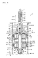
FIG. 1 is a vertical sectional view of a shock absorber showing theembodiment 1. -
FIG. 2 is a partially enlarged view ofFIG. 1 showing theembodiment 1. -
FIG. 3 is a graph showing the relationship between the moving speed of a piston rod and the damping force (damping force characteristic). -
FIG. 4 is a counterpart ofFIG. 1 showing theembodiment 2. -
FIG. 5 is a counterpart ofFIG. 1 showing theembodiment 3. -
FIG. 6 is a counterpart ofFIG. 2 showing theembodiment 4. -
FIG. 7 is a counterpart ofFIG. 2 showing the embodiment 5. -
FIG. 8 is a counterpart ofFIG. 1 showing the embodiment 6. -
- 1
- shock absorber
- 2
- vehicle
- 3
- vehicle body side
- 4
- vehicle wheel side
- 7
- shaft center
- 8
- cylinder tube
- 10
- one end
- 12
- another end
- 17
- first piston
- 18
- second piston
- 19
- first chamber
- 20
- intermediate chamber
- 21
- second chamber
- 22
- one end side
- 23
- piston rod
- 31
- oil
- 34
- pressure side first damping force generating device
- 35
- pressure side second damping force generating device
- 36
- first valve
- 39
- first orifice
- 41
- second valve
- 44
- second orifice
- 46
- extension side first damping force generating device
- 47
- extension side second damping force generating device
- 50
- intermediate unit
- 53
- free piston
- 54
- oil storage chamber
- 55
- tube
- 56
- gas enclosure chamber
- 62
- regulation device
- 73
- narrow section
- 74
- passage
- 75
- valve
- A
- first input force
- A'
- second input force
- B
- compression action
- C
- extension action
- D1, D2
- outer diameter
- PI, PN, P2
- hydraulic pressure
- V
- moving speed
- To achieve the object of the hydraulic shock absorber in the present invention are: In a case that the shock absorber performs compression or extension actions by application of the first and the second input forces from outside, as in the initial stage of the action, when the moving speed of the piston rod in relation to the cylinder tube is slow, the "response" is restrained to be low, while, when the first and the second input forces are large, and the moving speed is fast, the "response" is set high; By equipping this shock absorber to a vehicle, the driving feel on the vehicle becomes softer, and at the same time, when the large first and second input forces are applied, by absorbing the impact without delay, the driving feel on the vehicle is further improved, and also the driving stability is improved, the best mode for carrying out the present invention is as follows.
- That is, the shock absorber includes: a first and a second pistons, which are inserted in the cylinder tube slidably in the axial direction, and divide the inside of the cylinder tube to first chamber, intermediate chamber, and second chamber, from one end to another end in this order; a piston rod in which one end is connected to the first and the second pistons, and another end is protruded from another end of the cylinder tube to outside of the cylinder tube; a pressure side first damping force generating device for absorbing the first input force by flowing the oil from the first chamber through the first piston toward the intermediate chamber, when the first input force is applied from outside to enter the piston into the cylinder tube; and a pressure side second damping force generating device for absorbing the first input force, by flowing the oil from the intermediate chamber through the second piston toward the second chamber, when the first input force is applied.
- The shock absorber also includes: an extension side first damping force generating device for absorbing the second input force, by flowing the oil from the intermediate chamber through the first piston to the first chamber, when the second input force is applied from outside to evacuate the piston rod from the cylinder tube; and an extension side second damping force generating device for absorbing the second input force by flowing oil from the second chamber through the second piston to the intermediate chamber, when the second input force is applied.
- When the moving speed of the piston rod in relation to the cylinder tube is slow, the damping forces of the pressure side and the extension side first damping force generating devices are set greater than that of the pressure side and the extension side second damping force generating devices, while, when the moving speed is fast, the damping forces of the pressure side and the extension side second damping force generating devices are greater than that of the pressure side and the extension side first damping force generating devices, and the gas enclosure chamber filled with gas is connected to the first chamber through a free piston.
- The details of the present invention will now be described in accordance with the first embodiment with reference to
FIGs. 1 to 3 of the accompanying drawings. - The
reference numeral 1 is a hydraulic shock absorber inFIGs.1 and2 . This hydraulic shock absorber is applied in the suspension devices for automobile or motorcycle that is represented byvehicle 2. The hydraulic shock absorber is constructed between thevehicle body side 3 of thevehicle 2 and thevehicle wheel side 4 suspended to thevehicle body side 3. - The
hydraulic shock absorber 1 includes a single cylindertype cylinder tube 8 that has a shaft center toward the longitudinal direction. Thiscylinder tube 8 includes atube body 9 located above theshaft center 7, acap 11 for closing the opening of the lower end of thetube body 9 which is oneend 10 of thecylinder tube 8, and ahead cover 13 for closing the opening of the upper end of thetube body 9 which is anotherend 12 of thecylinder tube 8. The oneend 10 of thecylinder tube 8 is pivot supported by apivot shaft 14 in relation to the respectivevehicle wheel side 4. - A plurality of first and
second pistons cylinder tube 8 so that they can slide in the axial direction. Thefirst piston 17 is disposed at the oneend 10 side of thecylinder tube 8, and thesecond piston 18 is disposed at anotherend 12 side of thecylinder tube 8. The first and thesecond pistons cylinder tube 8 intofirst chamber 19,intermediate chamber 20, andsecond chamber 21 in the respective order from oneend 10 side to anotherend 12 side. - A
piston rod 23 is located above theshaft center 7. Oneend side 22 of thepiston rod 23 is connected to the first and thesecond pistons cylinder tube 8. The oneend side 22 of thepiston rod 23 passes through the center of the first and thesecond pistons second pistons end side 22 of thepiston rod 23 by acoupling tool 24. - The
coupling tool 24 includes: awasher 25 that is fitted onto thepiston rod 23 to sandwich the first and thesecond pistons spacer 26 that is fitted on to thepiston rod 23 and disposed between the first and thesecond pistons fastener 29 that fastens the first and thesecond pistons washer 25, andspacer 26 as one unit in relation to a step-difference-surface 28 formed between the oneend side 22 and anotherend side 27 of thepiston rod 23. An edge of anotherend side 27 of thepiston rod 23 is pivot supported by thepivot shaft 30 in relation to thevehicle body side 3. Inside of thecylinder tube 8 is filled with hydraulic fluid that isoil 31. The kinetic viscosity of theoil 31 is supposed to be four to ten centistokes (cSt) at thetemperature 40°C. - When first input force A is applied from outside to the
shock absorber 1 to enter thepiston rod 23 into thecylinder tube 8, in other words when the shock absorber is in compression action B, a pressure side damping force generating device 34 absorbs the first input force A by flowing theoil 31 from thefirst chamber 19 through thepiston 17 toward theintermediate chamber 20. When the first input force A is applied to set theshock absorber 1 in the compression action B, a pressure side second dampingforce generating device 35 absorbs the first input force A by flowing theoil 31 from theintermediate chamber 20 through thesecond piston 18 toward thesecond chamber 21. - The pressure side first damping force generating device 34 includes a pressure side first valve 36. A plurality of valve holes 37 that pass through the
first piston 17 are formed on thefirst piston 17 in the circumferential direction at the certain spacing. These valve holes 37 communicate thefirst chamber 19 and theintermediate chamber 20, respectively. The first valve 36 includes a pressure sideleaf valve body 38 that can open and close and resiliently close the exit side of thevalve hole 37. Anotch 37a is formed on the entrance side of thevalve hole 37. Theleaf valve body 38 is constituted with a plurality (two pieces) of disc form leaf that has different diameters with one another. Theleaf valve body 38 is supported to thepiston rod 23 between thefirst piston 17 and thewasher 25 of thecoupling tool 24 through aleaf sheet 40. - When the first input force A is applied to the
shock absorber 1 then theshock absorber 1 performs the compression action B, theleaf valve body 38 is opened by a first hydraulic pressure difference (P1-PN) between a hydraulic pressure P1 in thefirst chamber 19 and a hydraulic pressure PN of theintermediate chamber 20. Then theoil 31 flows from thefirst chamber 19 through thenotch 37a and thevalve hole 37 toward theintermediate chamber 20. The pressure side first damping force generating device 34 includes thefirst orifice 39 with circular sections formed in thefirst piston 17. Thefirst orifice 39 communicates thefirst chamber 19 and theintermediate chamber 20 through thevalve hole 37 in thefirst piston 17. - The pressure side second damping
force generating device 35 includes a pressure side second valve 41. Pluralities of valve holes 42 that pass through thesecond piston 18 are formed in thesecond piston 18 in the circumferential direction at certain spacing. These valve holes 42 communicate theintermediate chamber 20 and thesecond chamber 21 to each other. The second valve 41 includes a pressure sideleaf valve body 43 that can open, close and resiliently close the exit side of thevalve hole 42. Anotch 42a is formed at the entrance side of thevalve hole 42. Theleaf valve body 43 is made of the plurality of disc form leaf springs, each has different dimension, piled together. Theleaf valve body 43 is disposed between thesecond piston 18 and thewasher 25 of thefastener 24 through theleaf sheet 45, and supported to thepiston rod 23. The first valve 36 includes a pressure sideleaf valve body 38 that can open and close, and resiliently close the exit side of thevalve hole 37. Anotch 37a is formed on the entrance side of thevalve hole 37. Theleaf valve body 38 is constituted with a plurality (two pieces) of disc form leaf that has different dimension with one another piled together. Theleaf valve body 38 is disposed between thefirst piston 17 and thewasher 25 of thefastener 24, and supported to thepiston rod 23. - When the first input force A is applied and the
shock absorber 1 performs the compression action B, theleaf valve body 43 is opened by second hydraulic pressure difference (PN-P2) between hydraulic pressure PN in theintermediate chamber 20 and hydraulic pressure P2 of thesecond chamber 21. Then theoil 31 flows from theintermediate chamber 20 through thenotch 42a and thevalve hole 42 toward thesecond chamber 21. The pressure side second dampingforce generating device 35 includes thesecond orifice 44 with circular sections formed in thesecond piston 18. Thesecond orifice 44 communicates theintermediate chamber 20 and thesecond chamber 21 through thevalve hole 42 in thesecond piston 18. - In
FIG. 3 , if the moving speed V of thepiston rod 23 into thecylinder tube 8 is slow (VL inFIG. 3 ) when theshock absorber 1 is in the compression action B, the damping force of the pressure side first damping force generating device 34 is supposed to be larger than that of the pressure side second dampingforce generating device 35. On the other hand, if the moving speed V is fast (VH inFIG. 3 ) , the damping force of the pressure side second dampingforce generating device 35 is defined to be larger than that of the pressure side first damping force generating device 34. - As a concrete constitution to achieve this, a valve opening pressure characteristic of the first valve 36 is set weaker than that of the second valve 41. In other words, a value of the first hydraulic pressure difference (P1-PN) for initiating the valve opening of the first valve 36 of the
first piston 17 is smaller than a value of the second hydraulic pressure difference (PN-P2) for initiating the valve opening of the second valve 41 of thesecond piston 18. A cross section of theorifice 39 is smaller than the cross section of thesecond orifice 44. In this case, the cross section of thesecond orifice 44 is one-and-half times to ten times larger than the cross section of thefirst orifice 39. An each cross section of the first and thesecond orifices - On the other hand, when the second input force A' is applied to the opposite direction of the first input force A then the
piston rod 23 exits from thecylinder tube 8, in other words, when theshock absorber 1 performs the extension action C, an extension side first dampingforce generating device 46 absorbs the second input force A' by flowing theoil 31 from theintermediate chamber 20 through thefirst piston 17 to thefirst chamber 19. The extension side first dampingforce generating device 46 includes an extension side first valve 36' , valve hole 37' ,notch 37a' , leaf valve body 38', and leaf sheet 40', that are generally same as the pressure side first damping force generating device 34 in the constitution, shape, and action. Thefirst orifice 39 and a part of thevalve hole 37 that communicates to this are commonly used in the extension side first dampingforce generating device 46. - When the second input force A' is applied then the
shock absorber 1 performs the extension action C, the extension side second dampingforce generating device 47 absorbs the second input force A' by flowing theoil 31 from thesecond chamber 21 through thesecond piston 18 to theintermediate chamber 20. The extension side second dampingforce generating device 47 includes the extension side second valve 41', valve hole 42' ,notch 42a' , leaf valve body 43', and leaf sheet 45' , that are generally same as the pressure side second dampingforce generating device 35 in the constitution, shape, and action. Thesecond orifice 44 and a part of thevalve hole 42 that communicates to this are commonly used in the extension side second dampingforce generating device 47. - In above case, the
notch 37a of the pressure side first damping force generating device 34 is not formed around the leaf valve body 38' of the extension side first dampingforce generating device 46. Thenotch 37a communicates thevalve hole 37 to thefirst chamber 19. Thenotch 37a' of the extension side first dampingforce generating device 46 is not formed around theleaf valve body 38 of the pressure side first damping force generating device 34. Thenotch 37a communicates thevalve hole 37 to theintermediate chamber 20. On the other hand,notch 42a of the pressure side second dampingforce generating device 35 is not formed around the leaf valve body 43' of the extension side second dampingforce generating device 47. Thenotch 42a communicates thevalve hole 42 to theintermediate chamber 20. Thenotch 42a' of the extension side second dampingforce generating device 47 is not formed around theleaf valve body 43 of the pressure side second dampingforce generating device 35. Thenotch 42a' communicates the valve hole 42' to thesecond chamber 21. In the respective figures the leaf valve body is shown by the cross section, however hatching is not applied for a convenience object. - A
spring 49 for applying force in order to extension theshock absorber 1 is constructed between thevehicle body side 3 and thecylinder tube 8. The applying force of thespring 49 is equivalent to the second input force A'. - An
accumulator 51 is disposed to constantly pressurize thefirst chamber 19,intermediate chamber 20, and theoil 31 in thesecond chamber 21. Theaccumulator 51 is disposed as a separate unit from thecylinder tube 8. Theaccumulator 51 includes: anothercylinder tube 52 supported to thevehicle body side 3; afree piston 53 inserted in thecylinder tube 52 slidably in the axial direction; and atube 55 for communicating an oil storage chamber 54 to thefirst chamber 19. The oil storage chamber 54 is one of two chambers in thecylinder tube 52 that is divided by thefree piston 53. The oil storage chamber 54 is filled with theoil 31. Agas enclosure chamber 56 that is the other chamber in thecylinder tube 42 is filled with a high-pressure nitrogen gas. The nitrogen gas is compressible, and it's in the compressed form in this case. In other words, thegas enclosure chamber 56 is in communication with thefirst chamber 19 through thefree piston 53. - During the
vehicle 2 is driving, theshock absorber 1 performs the compression action B when the first input force A is applied from outside from the driving road through thevehicle wheel side 4. At this time, at first, theoil 31 in thefirst chamber 19 is flown from thefirst chamber 19 through the pressure side first damping force generating device 34 in thefirst piston 17 toward theintermediate chamber 20. Furthermore, theoil 31 in theintermediate chamber 20 is flown from theintermediate chamber 20 through the pressure side second dampingforce generating device 35 in thesecond piston 18 toward thesecond chamber 21. The pressure side first and second dampingforce generating devices 34, 35 attempt to generate the damping force coordinately by respectively flowing theoil 31. - In above case, at the initial stage in the compression action B by the
shock absorber 1, thefirst chamber 19 is compressed by the entering action of the first and thesecond pistons piston rod 23 into thecylinder tube 8, and its hydraulic pressure in thefirst chamber 19 tries to rise. - However, as described above, the
gas enclosure chamber 56 filled with gas is connected to thefirst chamber 19 through thefree piston 53. Thus, when thefirst chamber 19 is compressed and its hydraulic pressure P1 is beginning to rise, the hydraulic pressure in thefirst chamber 19 is restrained from rising by the motion of thefree piston 53 and the compression of the gas in thegas enclosure chamber 56. Therefore, theoil 31 is prevented from immediately flowing in the pressure side first damping force generating device 34 from thefirst chamber 19 toward theintermediate chamber 20 and thesecond chamber 21 by the hydraulic pressure P1 in thefirst chamber 19. - At the initial stage in the compression action B of the
shock absorber 1, thesecond chamber 21 is expanded by the entering action of the first and thesecond pistons cylinder tube 8, then its hydraulic pressure P2 is decreased. In order to make up the shortage of theoil 31 in thissecond chamber 21, the generally same amount ofoil 31 flows from thefirst chamber 19 andintermediate chamber 20 through thefirst orifice 39 in thefirst piston 17 and thesecond orifice 44 in thesecond piston 18 toward thesecond chamber 21. Thus the hydraulic pressure PN in theintermediate chamber 20 decreases in relation to the hydraulic pressure P1 in thefirst chamber 19. At the same time, the hydraulic pressure PN decreases in relation to the hydraulic pressure PN in theintermediate chamber 20. - Furthermore, as described above, the cross section of the
first orifice 39 in the pressure side first damping force generating device 34 in thefirst piston 17 is smaller than that of thesecond orifice 44 in the pressure side second dampingforce generating device 35 in thesecond piston 18. Therefore, the first hydraulic pressure difference (P1-PN) caused by thefirst orifice 39 is larger than the second hydraulic pressure difference (PN-P2) caused by thesecond orifice 44. - That is, when the
shock absorber 1 is in the initial stage of the compression action B, and when the moving speed V is slow (O-a inFIG. 3 ), the pressure side first damping force generating device 34 between the pressure side first and second dampingforce generating devices 34, 35, generates the damping force dominantly, then the damping force in this pressure side first damping force generating device 34 becomes larger than that of the pressure side second dampingforce generating device 35. - When the
shock absorber 1 is in the compression action B, the capacity of thecylinder tube 8 decreases for an amount of thepiston rod 23 entered to thecylinder tube 8. Accordingly, the amount of oil equivalent to the decreased capacity is flown from thefirst chamber 19 through thetube 55 into the oil storage chamber 54, by the motion of thefree piston 53 in theaccumulator 51 and the compression of the gas in thegas enclosure chamber 56. Therefore the compression action B of theshock absorber 1 is performed smoothly. - If the moving speed V at the compression action B increases further and the first hydraulic pressure difference (P1-PN) between the hydraulic pressure P1 in the
first chamber 19 and the hydraulic pressure PN in theintermediate chamber 20 reach the open valve pressure, this first valve 36 opens ("a" inFIG. 3 ). Theoil 31 in thefirst chamber 19 flows through the first valve 36 in addition to thefirst orifice 39 toward theintermediate chamber 20. Thus, the increase gradient of the damping force according to this pressure side first damping force generating device 34 is lowered ("a-b" inFIG. 3 ). The opening of the first valve 36 becomes larger when the first hydraulic pressure difference (P1-PN) is larger. - As described above, when the flow amount of the
oil 31 flowing thefirst orifice 39 and the first valve 36 in the pressure side first damping force generating device 34 is increased according to an increase in the moving speed V, a flow resistance increases because theoil 31 flows in thesecond orifice 44 in the pressure side second dampingforce generating device 35. Therefore the damping force of this pressure side second dampingforce generating device 35 increases ("a-c" inFIG. 3 ). - As the moving speed V in the compression action B increases ("d" in
FIG. 3 ), the damping force of the pressure side second dampingforce generating device 35 crosses the value once same as the damping force of the pressure side first damping force generating device 34. While the moving speed V is slow like until the crossing point (0-d=VL inFIG. 3 ), the damping force of the pressure side first damping force generating device 34 is larger than that of the pressure side second dampingforce generating device 35. However, when the moving speed V is faster ("d-b" inFIG. 3 ) like after the crossing poing, the damping force of the pressure side second dampingforce 35 becomes larger than that of the pressure side first damping force generating device 34. - The second valve 41 opens ("c" in
FIG. 3 ), when the moving speed V in the compression action B further increases, and the flow amount in thesecond orifice 44 in the pressure side second dampingforce generating device 35 increases, and the flow resistance increases, and the second hydraulic pressure difference (PN-P2) between the hydraulic pressure PN of theintermediate chamber 20 and the hydraulic pressure P2 of thesecond chamber 21 reach the open valve pressure of the second valve 41 of the pressure side second dampingforce generating device 35. Theoil 31 in theintermediate chamber 20 flows through the second valve 41 in addition to thesecond orifice 44 toward thesecond chamber 21. Thus, the increase gradient of the damping force by this pressure side second dampingforce generating device 35 is lowered ("c-b" inFIG. 3 ) . The opening of the second valve 41 becomes larger as the second hydraulic pressure difference (PN-P2) grows larger. - A sum of each damping force of the pressure side first damping force generating device 34 and the pressure side second damping
force generating device 35 at each point of the moving speed V in the compression action B is defined as the pressure side damping force characteristic (dashed line inFIG. 3 ) of theshock absorber 1. - Here, as described above, while the moving speed V of the
piston rod 23 in relation to thecylinder tube 8 is slow (VL inFIG. 3 ) as in the initial stage of the compression action B of theshock absorber 1, the pressure side first damping force generating device 34 among the pressure side first and second dampingforce generating devices 34, 35 generates the damping force dominantly, while the pressure side second dampingforce generating device 35 barely generates the damping force. Therefore, theintermediate chamber 20 and thesecond chamber 21 in the back of the moving direction of the first and thesecond pistons piston rod 23 decrease their hydraulic pressure PN, P2 concurrently. The decreasing pressure in each chamber is generally same. Thus, theintermediate chamber 20 and thesecond chamber 21 functions like a single unit. - In above case, the capacity of the
intermediate chamber 20 and thesecond chamber 21 together is larger than the capacity of each single chamber. Then the volume change amount by the "bulk modulus" of theoil 31 in theintermediate chamber 20 and thesecond chamber 21 is maintained large (soft). Therefore, the decrease speed of the hydraulic pressure PN, P2 is kept small. Therefore, immediate flow of theoil 31 in the pressure side first damping force generating device 34 from thefirst chamber 19 through the pressure side first damping force generating device 34 toward the intermediate 20 and thesecond chamber 21 are prevented. That is, the "response" is kept low at the initial stage in the compression action B of theshock absorber 1, and the sudden regulation of thepiston rod 23 entering into thecylinder tube 8 is prevented. - As a result, if the
shock absorber 1 is equipped to thevehicle 2, avehicle 2 provides a soft impression to a driver at the initial stage in the compression action B of theshock absorber 1 when the first input force A is applied from the ground. Therefore, an action effect, which is an achievement to an improved driving feel of thevehicle 2, is produced. - When the moving speed V in the compression action B increases, the damping force of the pressure side second damping
force generating device 35 becomes larger than the that of the pressure side first damping force generating device 34, then the pressure side second dampingforce generating device 35 generates the damping force dominantly. Therefore, thesecond chamber 21 at the back in the moving direction of thesecond piston 18 becomes larger, and its hydraulic pressure P2 decreases. - Here, the capacity of the
second chamber 21 alone is small. So the volume change amount by the "bulk module" of theoil 31 in thissecond chamber 21 is small (hard). Therefore, according to the entering action of thesecond piston 18, the decrease speed of the hydraulic pressure P2 of thesecond chamber 21 becomes faster, then the "response" in the pressure side second dampingforce generating device 35 becomes higher. - As a result, if the
shock absorber 1 is equipped to thevehicle 2, the impact energy based on the impact force applied to thevehicle 2 is immediately absorbed by the pressure side second dampingforce generating device 35, when the moving speed V is fast at the compression action B of theshock absorber 1 compressed by the first input force A applied from the ground, during thevehicle 2 is driving. Therefore, another "action effect", which is an achievement to an improved driving stability of thevehicle 2, is also produced. - When the compression action B of the
shock absorber 1 progresses, the applying force of thespring 49 increases as much. When the first input force A is equivalent to the applying force of thespring 49, the compression action B of theshock absorber 1 finishes. Then, the applying force of thespring 49, that is, the second input force A' makes theshock absorber 1 perform an extension action C to return to its original length. - As described above, when the shock absorber1 is applied with second input force A' that is an applying force of the
spring 49 and performs the extension action C, theoil 31 in thesecond chamber 21 flows from thesecond chamber 21 through the extension side second dampingforce generating device 47 in thesecond piston 18 toward theintermediate chamber 20. Also, theoil 31 in theintermediate chamber 20 flows from theintermediate chamber 20 through the extension side first dampingforce generating device 46 in thefirst piston 17 toward thefirst chamber 19. In this way the extension side first and second dampingforce generating devices oil 31 in these respectively. - In above case, at the initial stage in the extension action C of the
shock absorber 1, thefirst chamber 19 is expanded by the exit action of the first and thesecond pistons piston rod 23 from thecylinder tube 8, and the hydraulic pressure P1 in thefirst chamber 19 tries to decrease. - However, as described above, the
gas enclosure chamber 56 filled with gas is connected to thefirst chamber 19 through thefree piston 53. Thus, when thefirst chamber 19 expands and its hydraulic pressure P1 begins to decrease, the hydraulic pressure P1 in thefirst chamber 19 is restrained from decreasing by the motion of thefree piston 53 and the expansion of the gas in thegas enclosure chamber 56. Therefore, theoil 31 is prevented from immediately flowing from theintermediate chamber 20 and thesecond chamber 21 through the extension side first dampingforce generating device 46 toward thefirst chamber 19 by the hydraulic pressure P1 in thefirst chamber 19. - At the initiation of the extension action C of the
shock absorber 1, thesecond chamber 21 is compressed by the exit action of the first and thesecond pistons cylinder tube 8, and its hydraulic pressure P2 is increased. In order to discharge the excessive oil in thesecond chamber 21, generally same amount of oil flows from thesecond chamber 21 through theorifice 39 in thefirst piston 17 and through thesecond orifice 44 in thesecond piston 18 toward thefirst chamber 19 and theintermediate chamber 20. Thus the hydraulic pressure PN in theintermediate chamber 20 increases in relation to the hydraulic pressure P1 in thefirst chamber 19. At the same time, the hydraulic pressure P2 increases in relation to the hydraulic pressure PN in theintermediate chamber 20. - Furthermore, as described above, the cross section of the
first orifice 39 in the extension side first dampingforce generating device 46 in thefirst piston 17 is smaller than that of thesecond orifice 44 in the extension side second dampingforce generating device 47 in thesecond piston 18. Therefore, the first hydraulic pressure difference (PN-P1) caused by thefirst orifice 39 is larger than the second hydraulic pressure difference (P2-PN) caused by theorifice 44. - Here, the action of the
shock absorber 1 at the extension action C, inFIG. 3 , is equivalent to the 180 degree reversed figure ofFIG. 3 toward below, with a horizontal line as a reference, which indicates the damping force is zero. With reference to an imaginary reversedfigure 3 , the action of theshock absorber 1 at the extension action C is explained. Note that pressure side in the reversedFIG. 3 means extension side. - When the
shock absorber 1 is in the initial stage of the extension action C, and when the moving speed V is slow (O-a in reversedFIG. 3 ), the extension side first dampingforce generating device 46 between the extension side first and second dampingforce generating devices force generating device 46 becomes larger than that of the extension side second dampingforce generating device 47. - When the
shock absorber 1 is in the extension action C, the capacity of thecylinder tube 8 increases as much as thepiston rod 23 enters to thecylinder tube 8. In this case, the amount of oil equivalent to the increased capacity is flown from the oil storage chamber 54 through thetube 55 into thefirst chamber 19, by the motion of thefree piston 53 in theaccumulator 51 and by the expansion of gas in thegas enclosure chamber 56. Therefore the extension action C of theshock absorber 1 is performed smoothly. - When the moving speed V at the extension action C increases and when the first hydraulic pressure difference (PN-P1) between the hydraulic pressure P1 in the
first chamber 19 and the hydraulic pressure PN in theintermediate chamber 20 reach the open valve pressure of the first valve 36' in the extension side first dampingforce generating device 46, this first valve 36' opens ("a" in reversedFIG. 3 ) . Theoil 31 in theintermediate chamber 20 flows through the valve 36' in addition to thefirst orifice 39 toward thefirst chamber 19. Thus, the increase gradient of the damping force by this extension side first dampingforce generating device 46 is lowered ("a-b" in reversedFIG. 3 ). The opening of the first valve 36' becomes larger as the first hydraulic pressure difference (PN-P1) is larger. - As described above, when the flow amount of the
oil 31 flowing thefirst orifice 39 and the first valve 36' in the extension side first dampingforce generating device 46 is increased according to an increase in the moving speed V, a flow resistance increases because theoil 31 flows in thesecond orifice 44 in the extension side second dampingforce generating device 47. Therefore the damping force of this pressure side second dampingforce generating device 35 increases ("a-c" in reversedFIG. 3 ). - In the mid course, as the moving speed V in the extension action C increases ("d" in reversed
FIG. 3 ), the damping force of the extension side second damping force generating device crosses the same value once as the damping force of the extension side first dampingforce generating device 46. While the moving speed V is slow like until the crossing point (0-d=VL in reversedFIG. 3 ), the damping force of the extension side first dampingforce generating device 46 is larger than that of the extension side second dampingforce generating device 47. However, when the moving speed V of the extension side second damping force generating device is faster ("d-b=VH" in reversedFIG. 3 ), the damping force of the extension side second dampingforce 47 becomes larger than that of the extension side first dampingforce generating device 46. - The second valve 41' opens ("c" in reversed
FIG. 3 ), when the moving speed V in the extension action C is further increased, and the flow amount in thesecond orifice 44 in the extension side second dampingforce generating device 47 increases, and its flow resistance increases, and the second hydraulic pressure difference (P2-PN) between the hydraulic pressure PN of theintermediate chamber 20 and the hydraulic pressure P2 of thesecond chamber 21 reach the open valve pressure of the second valve 41' of the extension side second dampingforce generating device 47. Theoil 31 in thesecond chamber 21 flows through the second valve 41' in addition to thesecond orifice 44 toward theintermediate chamber 20. Thus, the increase gradient of the damping force by this extension side second dampingforce generating device 47 is lowered ("c-b" in reversedFIG. 3 ). The opening of the second valve 41' becomes larger as the second hydraulic pressure difference (P2-PN) grows larger. - A sum of each damping force of the extension side first damping
force generating device 46 and the extension side second dampingforce generating device 47 at each point of the moving speed V in the extension action C is defined as the extension side damping force characteristic (dashed line in reversedFIG. 3 ). - Here, as described above, when the moving speed V of the
piston rod 23 in relation to thecylinder tube 8 is slow (VL in reversedFIG. 3 ), the damping force of the extension side first dampingforce generating device 46 is larger than that of the extension side second dampingforce generating device 47. Therefore, when the moving speed V is slow as in the initial stage in the extension action C of theshock absorber 1, the extension side first dampingforce generating device 46 among the extension side first and second dampingforce generating devices force generating device 47 barely generates the damping force. Therefore, thefirst chamber 19 and theintermediate chamber 20, at the back of the moving direction of the first and thesecond pistons piston rod 23, decrease their hydraulic pressure PI, PN. The pressure decrease in these is generally same, so thefirst chamber 19 and theintermediate chamber 20 function like a united single chamber. - In above case, the capacity of the
first chamber 19 and theintermediate chamber 20 together is larger than the capacity of each single chamber. Then the volume change amount by the "bulk modulus" of theoil 31 in thefirst chamber 19 and theintermediate chamber 20 is maintained large (soft) . Therefore, the increase speed of the hydraulic pressure PN, P2 in theintermediate chamber 20 and thesecond chamber 21 is kept small. Therefore, immediate flow of theoil 31 from theintermediate chamber 20 and thesecond chamber 21 through the extension side first dampingforce generating device 46 toward thefirst chamber 19 is prevented. That is, the "response" is kept low at the initial stage of the extension action C of theshock absorber 1, and the sudden regulation of thepiston rod 23 exiting from thecylinder tube 8 is prevented. - As a result, if the
shock absorber 1 is equipped to thevehicle 2, it provides a soft impression to a driver at the initial stage in the extension action C of theshock absorber 1 when the second input force A' is applied from thespring 49. Therefore, an action effect, which is an achievement to an improved driving feel of thevehicle 2, is more securely produced. - When the moving speed V in the extension action C increases, the damping force of the extension side second damping
force generating device 47 becomes larger than the extension side first dampingforce generating device 46, then the extension side second dampingforce generating device 47 generates the damping force dominantly. Therefore, thesecond chamber 21 at the front in the moving direction of thesecond piston 18 becomes smaller, and its hydraulic pressure P2 increases. - Here, the capacity of the
second chamber 21 alone is small. So the volume change amount by the "bulk module" of theoil 31 in thissecond chamber 21 is small (hard).
Therefore, according to the exit action of thesecond piston 18, the increase speed of the hydraulic pressure P2 in thesecond chamber 21 becomes faster, then the "response" in the extension side second dampingforce generating device 47 becomes higher. - As a result, if the
shock absorber 1 is equipped to thevehicle 2, the impact energy based on the second input force A' is immediately absorbed by the extension side second dampingforce generating device 47, when the moving speed V is fast at the extension action C of theshock absorber 1 by the second input force A' applied from thespring 49, during thevehicle 2 is driving. Therefore, another "action effect", which is an achievement to an improved driving stability of thevehicle 2, is more securely produced. - Hereafter, the compression action B and the extension action C are repeated by turns, so that the respective first and second input forces A, A' is absorbed, and the smooth progress of the
vehicle 2 is maintained. - As described above, the cross section of the
second orifice 44 is one-and-half to ten times larger than the cross section of thefirst orifice 39. - Here, if the cross section of the
second orifice 44 is less than one-and-half times of the cross section of thefirst orifice 39, each cross sectional value of the first and thesecond orifices shock absorber 1 is in the compression action C or extension action C after applied with the first and the second input forces A, A' , theoil 31 flows in the pressure side first and second dampingforce generating devices 34, 35, or in the extension side first and second dampingforce generating devices - On the other hand, if the cross section of the
second orifice 44 is more than ten times of the cross section of thefirst orifice 39, the cross section of thesecond orifice 44 becomes oversized. Then, the expected damping force becomes difficult to get even if theoil 31 flows in thesecond orifice 44. Therefore, it is even more difficult to get the expected damping force when the moving speed V is fast (VH inFIG. 3 ) . - For above reasons, the diameters of the first and the
second orifices - As described above, the kinetic viscosity of the
oil 31 is four to ten centistokes (cSt) at 40°C. - Here, when the
shock absorber 1 is repeatedly used, the temperature of theoil 31 rises, and then the kinetic viscosity tends to decrease. In general, the decrease width of the kinetic viscosity according to temperature is wider as the kinetic viscosity of theoil 31 is higher. - In general, the kinetic viscosity of the
oil 31 at the temperature of 40°C is one-and-half cSt, however, the decrease width of the kinetic viscosity according to temperature rising of theoil 31 becomes wider when this type ofoil 31 is used. Then it is difficult to finely obtain the expected damping force to theshock absorber 1. At the same time, as in the above configuration, wider parts are subject to an effect (resistance) of the viscosity of theoil 31 as for theshock absorber 1 using a plurality of pistons. In order to refrain the effect as much as possible, it is advantageous to use the mixture with thelow viscosity oil 31 lower than the 10 centistokes. - On the other hand, when the viscosity of the
oil 31 is less than four, the consumption increases and the durability lowers according to the decrease of the lubrication in theoil 31, because the viscosity of theoil 31 is too low. - Therefore, as described above, the kinetic viscosity of the
oil 31 at the temperature of 40°C is defined between four to ten cSt, so that the "action effect" is more securely produced. The kinetic viscosity is further preferable to be between five to eight cSt. - The above is an example along with provided figures, however, the
shock absorber 1 may be disposed upside down or horizontally or obliquely. The flow resistance (pressure loss) of theoil 31 in thefirst orifice 39 may be set higher than that of thesecond orifice 44, by setting the cross section of the first and thesecond orifices first orifice 39 longer than that of thesecond orifice 44. The first and thesecond orifices second orifice 44 are more than those of thefirst orifice 39. - The following figures show the
embodiments 2 to 6. The respective embodiments are common in many points in the configuration and action effect. Therefore these common things are indicated by the same reference numeral then the same explanation is omitted, and the following is described mainly for those with different points. The configuration of the respective parts in the respective embodiment may be arranged for suitable match according to the object of the present invention and the action effect. - For further detail description of the present invention, the
embodiment 2 is now explained according to the providedFIG. 4 . - In
FIG. 4 , anintermediate piston 60 is inserted to thecylinder tube 8 in the way theintermediate piston 60 can slide in the axial direction. Theintermediate piston 60 is disposed between the first and thesecond pistons piston rod 23. Theintermediate chamber 20 is divided to two chambers by theintermediate piston 60. Although not shown, the pressure side and the extension side intermediate damping force generating devices, which has same configuration and effect as extension side first dampingforce generating devices 34, 46, and pressure side and extension side second dampingforce generating devices - In above case, the intermediate damping force generating device opens the valve according to the value between the first hydraulic pressure difference (P1-PN) and the second hydraulic pressure difference (PN-P2), and flows the
oil 31 so as to passing through theintermediate piston 60. The cross section of the intermediate damping force generating device, is a value between the cross sections of the respective first and second orifices. - The
intermediate piston 60 can be disposed two or more. The location to dispose can be selected freely. - For further detail description of the present invention, the
embodiment 3 is now explained according to the providedFIG. 5 . - In
FIG. 5 , theaccumulator 51 is formed in thecylinder tube 8 as a single unit. Specifically, thefree piston 53 is inserted to thefirst chamber 19 in the way thefree piston 53 can slide in the axial direction. Thefirst chamber 19 is divided to two chambers by thefree piston 53. The high-pressure nitrogen gas is enclosed to the opposite chamber to thefirst piston 17 as reference to thefree piston 53. - The
shock absorber 1 can be made compactly according to this embodiment. - For further detail description of the present invention, the
embodiment 4 is now explained according to the providedFIG. 6 . -
FIG. 6 shows compression state B of theshock absorber 1. Theshock absorber 1 is equipped with aregulation device 62 that can change the cross sectional value of the intermediate, fast speed sidesecond orifice 44 according to the external control from theshock absorber 1. The following describes about thisregulation device 62. - Through-
hole 63 is formed in the way it passes through thepiston rod 23 on theshaft center 7. The opening in the oneend 10 side (lower end side) of the through-hole in thetube body 9 is closed. The through-hole 63 is in communication with theintermediate chamber 20 through apassage 65 that is formed in thespacer 26 extending in the longitudinal direction. Also the through-hole 63 is in communication with thesecond chamber 21 through theother passage 66 formed in thepiston rod 23. Theplug 67 is pressed into the through-hole 63 between the bothpassages second orifice 44 is formed on theshaft center 7 of theplug 67. - The
operation bolt 68 is inserted from another end (upper end) of the through-hole 63 and screwed to thepiston rod 23. Theneedle valve 69 is attached as a single unit to the entering end of theoperation bolt 68. Theneedle valve 69 faces against thesecond orifice 44. When theoperation bolt 68 is turned about by thetool 70, theneedle valve 69 moves coordinately, so that the practical cross sectional value of thesecond orifice 44 may be changed. Theneedle valve 69 may be fixed to thepiston rod 23 with thisoperation bolt 68 at the desired turning position. - According to the above configuration, a damping force characteristic of the
second orifice 44 may be changed to various values, between the intermediate to fast range in the moving speed V, and then may obtain the required characteristic, by controlling theregulation device 62. On the other hand, the cross section of thefirst orifice 39 in the pressure side and the extension side first dampingforce generating devices 34, 46 are fixed and maintained in the certain value regardless of the control on the regulation device. Therefore, if the shock absorber is equipped to thevehicle 2, a desired driving feel can be obtained, while maintaining the "action effect". - For further detail description of the present invention, the embodiment 5 is now explained according to the provided
FIG. 7 . -
FIG. 7 shows theshock absorber 1 in the compression action B. An outer diameter D1 of a part of thepiston rod 23 connected to thefirst piston 17 is smaller than an outer diameter D2 of another part of thepiston rod 23 connected to thesecond piston 18. Anotherend side 27 of thepiston rod 23 is bigger than the outer diameter D2. Therefore, at least two step-difference-surfaces 28 are formed in thepiston rod 23. The first and thesecond pistons fastening tool 29 to the each step-difference-surface 28. Thus, the first and thesecond pistons piston rod 23 rigidly. - According to above configuration, the outer diameter D1 of a part of the
piston rod 23 is smaller than the outer diameter D2 of another part of thepiston rod 23, thus the effective area at the end surface in the axial direction of thefirst piston 17 excluding the through section of thepiston rod 23 can be bigger than that of thesecond piston 18. - Flexibility for designing the pressure side and the extension side first damping
force generating devices 34, 46 can be improved, which is for example the effective surface of theleaf valve bodies 38, 38' of the first valves 36, 36' in the pressure side and the extension side first dampingforce generating devices 34, 46 attached to thefirst piston 17 can be bigger, or for example the flexure of theleaf valve bodies 38, 38' can be made easily and precisely. As a result, a tiny value of the damping force is obtained precisely, which is caused by the flow of theoil 31 through the first valves 36, 36' in the pressure side and the extension side first dampingforce generating devices 34, 46 when the moving speed V is extremely slow. Therefore the "action effect" is further aided. Embodiment 6 - For further detail description of the present invention, the embodiment 6 is now explained according to the provided
FIG. 8 . - In
FIG. 8 , a suspension system of thevehicle 2 includes a pair of theshock absorbers 1 and anintermediate unit 50 disposed between theseshock absorbers 1. Theshock absorbers 1 are respectively constructed between thevehicle body side 3 and the eachvehicle wheel side 4. In this case, the eachvehicle wheel side 4 may be left or right vehicle wheel side, or may be front or rear vehicle wheel side. Theintermediate unit 50 includes anaccumulator 51 having anotherfree piston 72 that is slidably inserted in the axial direction in the oil storage chamber 54 of theaccumulator 51. Anotherfree piston 72 is connected with thefree piston 53, and slide as a single unit. Anotherfree piston 72 divides the oil storage chamber 54 to two chambers. - A
passage 74 communicates thefirst chambers 19 of theshock absorber 1 to each other through anarrow section 73. Thenarrow section 73 is disposed in anotherfree piston 72, and includes a pair ofvalves 75 that has same configuration and action as the first valve 36. Thesevalves 75 accept the reverse flow of theoil 31 to each other. - The
passage 74 is constituted with, afirst tube 76 for communicating between one of thefirst chambers 19 and one of two chambers in the oil storage chamber 54 divided by anotherfree piston 72, and asecond tube 77 for communicating between the other one offirst chambers 19 and the other one of two chambers in the oil storage chamber 54, and the oil storage chamber 54. - Supposedly, one of the shock absorbers 1 (left side in
FIG. 8 ) performs compression action B by the first input force A. In this case, theoil 31 in thefirst chamber 19 in the leftside shock absorber 1 flows into the underside chamber of thefree piston 72 among the oil storage chamber 54 in theaccumulator 51 in theintermediate unit 50. Then, anotherfree piston 72 moves downward in reference to thecylinder tube 52 accompanied by thefree piston 53, and the capacity of the upper chamber in anotherfree piston 72. Then, theoil 31 in thefirst chamber 19 in the other (right side)shock absorber 1 between bothshock absorbers 1 is drawn into the chamber above anotherfree piston 72, and accordingly the rightside shock absorber 1 performs the compression action B. - The both
shock absorbers 1 perform the same action at the same time, so thevehicle 2 is protected against rolling or pitting. At the time when thevehicle 2 makes big motion that is when the moving speed V is fast, the bulk modulus of theoil 31 in theintermediate chamber 20 and thesecond chamber 21 of theshock absorber 1 is regulated to be low, due to the configuration of each embodiment according to each claim in the present document. Therefore, the precision for an amount ofoil 31 drawing in or out in reference to theintermediate unit 50 is improved. Also the precision for the "action effect" is improved. - The present invention can be achieved by suitably matching the individual components.
Claims (12)
- A hydraulic shock absorber comprising: a first and a second pistons (17, 18), which are inserted to a cylinder tube (8) slidably in the axial way, and divide an inside of this cylinder tube (8) to a first chamber (19), an intermediate chamber (20), and a second chamber (21) from its one end (10) to another end (12) in this order; a piston rod (23) in which one end (22) is connected to the first and the second pistons (17, 18), and another end protrudes from another end (12) of the cylinder tube (8) to outside of this cylinder tube (8); a pressure side first damping force generating device (34) for absorbing a first input force (A) by flowing an oil (31) from the first chamber (19) through the first piston (17) to the intermediate chamber (20), when the first input force (A) is applied from outside to enter the piston rod (23) into the cylinder tube (8); a pressure side second damping force generating device (35) for absorbing the first input force (A) by flowing the oil (31) from the intermediate chamber (20) through the second piston (18) to the second chamber (21), when the first input force (A) is applied; an extension side first damping force generating device (46) for absorbing a second input force (A') by flowing the oil (31) from the cylinder tube (8) through the first piston (17) to the first chamber (19), when the second input force (A') is applied from outside to evacuate the piston rod (23) from the cylinder tube (8) ; an extension side second damping force generating device (47) for absorbing the second input force (A') by flowing the oil (31) from the second chamber (21) through the second piston (18) to the intermediate chamber (20) when the second input force (A') is applied;
wherein, when a moving speed (V) of the piston rod (23) in relation to the cylinder tube (8) is slow (VL in FIG. 3), damping forces of the pressure side and the extension side first damping force generating devices (34, 46) are set greater than that of the pressure side and the extension side second damping force generating devices (35, 47), while, when the moving speed (V) is fast (VH in FIG. 3), the damping forces of the pressure side and the extension side second damping force generating devices (35, 47) are set greater than those of the pressure side and the extension side first damping force generating devices (34, 46), and a gas enclosure chamber (56) filled with gas is connected to the first chamber (19) through a free piston (53). - The hydraulic shock absorber according to claim 1, wherein the pressure side and the extension side first damping force generating devices (34, 46) comprise pressure side and extension side first valves (36, 36') for flowing the oil (31) to pass through the first piston (17) by a first hydraulic pressure difference (P1-PN) (PN-P1) between the first chamber (19) and the intermediate chamber (20), when the first and the second input forces (A, A') are applied, and first orifice (39) passing through the first piston (17) ; the pressure side and the extension side second damping force generating devices (35, 47) comprise pressure side and extension side second valves (41, 41') for flowing the oil (31) to pass through the second piston (18) by a second hydraulic pressure difference (PN-P2) (P2-PN) between the intermediate chamber (20) and the second chamber (21), when the first and the second input forces (A, A') are applied, and a second orifice (44) passing through the second piston (18); open valve pressure characteristics of the pressure side and the extension side first valves (36, 36') are set weaker than those of the pressure side and the extension side second valves (41, 41'); and a cross section of the first orifice (39) is set smaller than that of the second orifice (44).
- The hydraulic shock absorber according to claim 2, wherein a cross section of the second orifice (44) is set one-and-half to ten times of a cross section of the first orifice (39).
- The hydraulic shock absorber according to claim 1, wherein kinetic viscosity of the oil (31) is set between four to ten centistokes (cSt) at 40°C.
- The hydraulic shock absorber according to claim 2, wherein a regulation device (62) is disposed so that a value of a cross section of the second orifice (44) is variable.
- The hydraulic shock absorber according to claim 2, wherein an outer diameter (D1) of a part of the piston rod (23) connected to the first piston (17) is set smaller than an outer diameter (D2) of the other part of the piston rod (23) connected to the second piston (18).
- The hydraulic shock absorber according to claim 1, wherein another cylinder tube (52) is disposed as a separate unit from the cylinder tube (8), and the free piston (53) is inserted in the cylinder tube (52) slidably in the axial direction, and one of two chambers in the cylinder tube (52) divided by this free piston (53) is filled with the oil (31) then set as a oil storage chamber that communicates to the first chamber (19), while the other chamber is set as the gas enclosure chamber (56) filled with high pressure gas.
- The hydraulic shock absorber according to claim 1, wherein an intermediate piston (60) slidably inserted in the axial direction is disposed in the cylinder tube (8) so as to locate between the first piston (17) and the second piston (18) in the axial direction of the cylinder tube (8), and a pressure side and an extension side intermediate damping force generating devices that have same configuration and same action with the pressure side and the extension side first damping force generating devices (34, 46) or the pressure side and the extension side second damping force generating devices (35, 47) are disposed to the intermediate piston (60), and the intermediate piston (60) is connected to a one end (22) of the piston rod (23).
- The hydraulic shock absorber according to claim 1, wherein the free piston (53) is inserted in the first chamber (19) in the cylinder tube (8) slidably in the axial direction, between two chambers in the first chamber (19) comparted by the free piston (53), in reference to the free piston (53), an opposite side chamber to the first piston (17) is set as the gas enclosure chamber (56).
- The hydraulic shock absorber according to claim 5, wherein the regulation device (62) comprises a needle valve (69) inserted to a through-hole (63) formed on a shaft center (7) of the piston rod (23), and a cross section of a part of the second orifice (44) formed on the shaft center (7) of the piston rod (23), is variable by the needle valve (69).
- The hydraulic shock absorber according to claim 1, wherein the outer diameter (D1) of a part of the piston rod (23) connected to the first piston (17), is set smaller than the outer diameter (D2) of a part of the piston rod (23) connected to the second piston (18).
- The hydraulic shock absorber according to claim 1, wherein the hydraulic shock absorber (1) is applied to a suspension system of a vehicle (2), and constructed between a vehicle body side (3) of the vehicle (2) and respective vehicle wheel side (4) suspended to the vehicle body side 3.
Applications Claiming Priority (2)
| Application Number | Priority Date | Filing Date | Title |
|---|---|---|---|
| JP2005262224A JP4753238B2 (en) | 2005-09-09 | 2005-09-09 | Hydraulic shock absorber |
| PCT/JP2006/317776 WO2007029787A1 (en) | 2005-09-09 | 2006-09-07 | Hydraulic shock absorber |
Publications (3)
| Publication Number | Publication Date |
|---|---|
| EP1923596A1 true EP1923596A1 (en) | 2008-05-21 |
| EP1923596A4 EP1923596A4 (en) | 2011-12-21 |
| EP1923596B1 EP1923596B1 (en) | 2012-12-26 |
Family
ID=37835902
Family Applications (1)
| Application Number | Title | Priority Date | Filing Date |
|---|---|---|---|
| EP06797636A Active EP1923596B1 (en) | 2005-09-09 | 2006-09-07 | Hydraulic shock absorber |
Country Status (4)
| Country | Link |
|---|---|
| US (1) | US8381887B2 (en) |
| EP (1) | EP1923596B1 (en) |
| JP (1) | JP4753238B2 (en) |
| WO (1) | WO2007029787A1 (en) |
Cited By (4)
| Publication number | Priority date | Publication date | Assignee | Title |
|---|---|---|---|---|
| EP2249057A1 (en) * | 2009-05-06 | 2010-11-10 | HEMSCHEIDT FAHRWERKTECHNIK GmbH & Co. KG | Dampening device for wheeled vehicles |
| EP2405154A1 (en) | 2010-07-05 | 2012-01-11 | HEMSCHEIDT FAHRWERKTECHNIK GmbH & Co. KG | Dampening device for wheeled vehicles |
| ITMI20111890A1 (en) * | 2011-10-18 | 2013-04-19 | Caimi Export Spa | SHOCK |
| WO2019092480A1 (en) * | 2017-11-10 | 2019-05-16 | Maranini Simone | Shock absorbing system of a vehicle |
Families Citing this family (19)
| Publication number | Priority date | Publication date | Assignee | Title |
|---|---|---|---|---|
| JP4898512B2 (en) * | 2007-03-23 | 2012-03-14 | 株式会社ショーワ | Damping force generator |
| JP4919045B2 (en) * | 2007-04-19 | 2012-04-18 | 日立オートモティブシステムズ株式会社 | Damping force adjustable fluid pressure shock absorber |
| SE531694C2 (en) * | 2007-12-19 | 2009-07-07 | Oehlins Racing Ab | Shock absorber with double piston |
| JP5248852B2 (en) * | 2007-12-27 | 2013-07-31 | ヤマハ発動機株式会社 | Vibration damping device for car body |
| US8297418B2 (en) * | 2008-06-05 | 2012-10-30 | Tenneco Automotive Operating Company Inc. | Nested check high speed valve |
| TW201028329A (en) * | 2009-01-19 | 2010-08-01 | Y S S Thailand Co Ltd | Advanced triple piston damper |
| DE102011012730B4 (en) * | 2010-03-02 | 2021-04-29 | Hitachi Automotive Systems, Ltd. | Shock absorbers |
| CN103557260A (en) * | 2013-09-30 | 2014-02-05 | 太仓康茂电子有限公司 | Hydro-pneumatic spring |
| JP2015129552A (en) * | 2014-01-07 | 2015-07-16 | 株式会社ショーワ | Pressure buffer device |
| JP6259676B2 (en) * | 2014-02-13 | 2018-01-10 | 株式会社ショーワ | Pressure shock absorber |
| EP2913460B1 (en) | 2014-02-19 | 2017-08-23 | Chihiro Sangyo Co., Ltd. | Vibration control device for a building |
| JP5620596B1 (en) * | 2014-02-19 | 2014-11-05 | 千博産業株式会社 | Structure damping device |
| DE112016000579B4 (en) * | 2015-02-03 | 2024-03-28 | Tenneco Automotive Operating Company Inc. | SECONDARY DAMPING ARRANGEMENT FOR A SHOCK ABSORBER |
| WO2016127076A1 (en) * | 2015-02-06 | 2016-08-11 | Tenneco Automotive Operating Company Inc. | Secondary dampening assembly for a shock absorber |
| DE102018217372B3 (en) * | 2018-10-11 | 2020-03-05 | Zf Friedrichshafen Ag | Damper device and vehicle with the damper device |
| DE102018217371B3 (en) * | 2018-10-11 | 2020-01-23 | Zf Friedrichshafen Ag | Damper device and vehicle with the damper device |
| DE102019110219A1 (en) * | 2019-04-17 | 2020-10-22 | Bayerische Motoren Werke Aktiengesellschaft | Piston rod for a telescopic vibration damper with hydraulic end stop |
| EP3809012A1 (en) * | 2019-10-18 | 2021-04-21 | Öhlins Racing AB | Front fork position-dependent damping for bicycles and motorcycles |
| WO2023188284A1 (en) * | 2022-03-31 | 2023-10-05 | 日立Astemo株式会社 | Shock absorber, and suspension device |
Citations (1)
| Publication number | Priority date | Publication date | Assignee | Title |
|---|---|---|---|---|
| EP0748950A1 (en) * | 1995-05-18 | 1996-12-18 | Öhlins Racing Ab | Shock absorber device and use thereof |
Family Cites Families (21)
| Publication number | Priority date | Publication date | Assignee | Title |
|---|---|---|---|---|
| US2740500A (en) * | 1951-06-29 | 1956-04-03 | Gen Motors Corp | Shock absorber |
| DE1249037B (en) * | 1961-06-02 | 1967-08-31 | ||
| DE2551516B2 (en) * | 1975-11-17 | 1980-04-10 | Fa. August Bilstein, 5828 Ennepetal | Hydropneumatic single-tube vibration damper, especially steering damper |
| JPS5845293A (en) * | 1981-09-10 | 1983-03-16 | Idemitsu Kosan Co Ltd | Fluid composition for shock absorber |
| US4588053A (en) * | 1984-09-19 | 1986-05-13 | The United States Of America As Represented By The Secretary Of The Air Force | Multiple rate shock isolator damping valve |
| DE3446133A1 (en) * | 1984-12-18 | 1986-06-19 | Fichtel & Sachs Ag, 8720 Schweinfurt | VIBRATION DAMPER WITH VARIABLE DAMPING FORCE |
| JPH01295043A (en) * | 1988-05-20 | 1989-11-28 | Soqi Inc | Hydraulic buffer |
| JPH02168038A (en) * | 1988-09-30 | 1990-06-28 | Tokico Ltd | Hydraulic shock absorber |
| GB2250080B (en) * | 1990-10-19 | 1994-08-17 | Tokico Ltd | Hydraulic shock absorber |
| DE4203508A1 (en) * | 1992-02-07 | 1993-08-12 | Fichtel & Sachs Ag | ROTARY VALVE FOR A VIBRATION DAMPER WITH ADJUSTABLE DAMPING FORCE |
| DE19618055C1 (en) * | 1996-05-06 | 1998-01-15 | Mannesmann Sachs Ag | Piston-cylinder unit with path-dependent damping force field |
| SE9602507L (en) * | 1996-06-25 | 1997-12-26 | Oehlins Racing Ab | Shock |
| US5823306A (en) * | 1996-11-12 | 1998-10-20 | Tenneco Automotive Inc. | Stroke dependent damping |
| JPH10331898A (en) * | 1997-06-02 | 1998-12-15 | Toyota Motor Corp | Shock absorber |
| US6352145B1 (en) * | 1998-10-07 | 2002-03-05 | Tenneco Automotive Inc. | Stroke dependent damping |
| US6120049A (en) * | 1998-10-29 | 2000-09-19 | Answer Products, Inc. | Bicycle shock absorber including lockout means |
| SE515321C2 (en) * | 1998-12-02 | 2001-07-16 | Oehlins Racing Ab | Shock absorber with cylinder comprising a piston rod with at least two pistons |
| DE19945632B4 (en) * | 1999-09-23 | 2005-11-03 | Thyssenkrupp Bilstein Gmbh | Device for increasing the damping |
| US6776269B1 (en) * | 2003-06-18 | 2004-08-17 | Tenneco Automotive Operating Company, Inc. | Twin piston shock absorber |
| GB2412954A (en) * | 2004-04-08 | 2005-10-12 | Mojo Suspension Hoodoo Ltd | A damper for a vehicle suspension system |
| SE531694C2 (en) * | 2007-12-19 | 2009-07-07 | Oehlins Racing Ab | Shock absorber with double piston |
-
2005
- 2005-09-09 JP JP2005262224A patent/JP4753238B2/en not_active Expired - Fee Related
-
2006
- 2006-09-07 US US12/066,129 patent/US8381887B2/en active Active
- 2006-09-07 WO PCT/JP2006/317776 patent/WO2007029787A1/en active Application Filing
- 2006-09-07 EP EP06797636A patent/EP1923596B1/en active Active
Patent Citations (1)
| Publication number | Priority date | Publication date | Assignee | Title |
|---|---|---|---|---|
| EP0748950A1 (en) * | 1995-05-18 | 1996-12-18 | Öhlins Racing Ab | Shock absorber device and use thereof |
Non-Patent Citations (1)
| Title |
|---|
| See also references of WO2007029787A1 * |
Cited By (5)
| Publication number | Priority date | Publication date | Assignee | Title |
|---|---|---|---|---|
| EP2249057A1 (en) * | 2009-05-06 | 2010-11-10 | HEMSCHEIDT FAHRWERKTECHNIK GmbH & Co. KG | Dampening device for wheeled vehicles |
| EP2405154A1 (en) | 2010-07-05 | 2012-01-11 | HEMSCHEIDT FAHRWERKTECHNIK GmbH & Co. KG | Dampening device for wheeled vehicles |
| ITMI20111890A1 (en) * | 2011-10-18 | 2013-04-19 | Caimi Export Spa | SHOCK |
| WO2013057686A1 (en) * | 2011-10-18 | 2013-04-25 | Caimi Export S.P.A. | A shock absorber |
| WO2019092480A1 (en) * | 2017-11-10 | 2019-05-16 | Maranini Simone | Shock absorbing system of a vehicle |
Also Published As
| Publication number | Publication date |
|---|---|
| US20090101459A1 (en) | 2009-04-23 |
| US8381887B2 (en) | 2013-02-26 |
| JP4753238B2 (en) | 2011-08-24 |
| WO2007029787A1 (en) | 2007-03-15 |
| EP1923596B1 (en) | 2012-12-26 |
| EP1923596A4 (en) | 2011-12-21 |
| JP2007071367A (en) | 2007-03-22 |
Similar Documents
| Publication | Publication Date | Title |
|---|---|---|
| EP1923596B1 (en) | Hydraulic shock absorber | |
| US6446771B1 (en) | Shock absorber | |
| US5460355A (en) | Adjustable shock absorber | |
| EP2118515B1 (en) | Shock absorber with hydraulic flow ducts | |
| EP1664582B1 (en) | Stroke dependent damping | |
| EP1975453A2 (en) | Damping force adjustable fluid pressure shock absorber | |
| AU2012202898B2 (en) | Device for damping compressive forces | |
| CN1871452A (en) | Stroke dependent bypass | |
| EP2126403B1 (en) | Method for adjusting damping characteristics in a shock absorber | |
| EP2487384A1 (en) | Hydraulic shock absorbing device | |
| JP2000110881A (en) | Two-stage type shock absorber | |
| CA2468282A1 (en) | Adaptive shock damping control | |
| KR20010103710A (en) | Shock absorber assembly | |
| JP6454536B2 (en) | Shock absorber | |
| US20200247209A1 (en) | Spring-Absorber System with Variable Spring Rate | |
| US6634250B2 (en) | Steering column damper | |
| US6880684B1 (en) | Flow regulator for a gas shock absorber | |
| CN100422590C (en) | Booster to adapt air spring pressure for FDD shock absorber | |
| EP1521918B1 (en) | Hydraulic vehicle shock absorber | |
| CN110822005B (en) | Damping self-adaptive adjustment vibration reducer and automobile | |
| KR100361297B1 (en) | Shock absorber of automobile | |
| JP2007198548A (en) | Damping force generating device for hydraulic shock absorber | |
| JP2010216601A (en) | Orifice mechanism of shock absorber | |
| DE202004005623U1 (en) | Suspension and damping device for motor vehicles | |
| JP2007255608A (en) | Piston for hydraulic shock absorber |
Legal Events
| Date | Code | Title | Description |
|---|---|---|---|
| PUAI | Public reference made under article 153(3) epc to a published international application that has entered the european phase |
Free format text: ORIGINAL CODE: 0009012 |
|
| 17P | Request for examination filed |
Effective date: 20080310 |
|
| AK | Designated contracting states |
Kind code of ref document: A1 Designated state(s): AT BE BG CH CY CZ DE DK EE ES FI FR GB GR HU IE IS IT LI LT LU LV MC NL PL PT RO SE SI SK TR |
|
| A4 | Supplementary search report drawn up and despatched |
Effective date: 20111121 |
|
| RIC1 | Information provided on ipc code assigned before grant |
Ipc: F16F 9/50 20060101AFI20111115BHEP Ipc: F16F 9/32 20060101ALI20111115BHEP Ipc: F16F 9/44 20060101ALI20111115BHEP Ipc: F16F 9/06 20060101ALI20111115BHEP Ipc: F16F 9/348 20060101ALI20111115BHEP Ipc: F16F 9/46 20060101ALI20111115BHEP |
|
| RIC1 | Information provided on ipc code assigned before grant |
Ipc: F16F 9/50 20060101AFI20120302BHEP Ipc: F16F 9/46 20060101ALI20120302BHEP Ipc: F16F 9/348 20060101ALI20120302BHEP Ipc: F16F 9/32 20060101ALI20120302BHEP Ipc: F16F 9/06 20060101ALI20120302BHEP Ipc: F16F 9/44 20060101ALI20120302BHEP |
|
| GRAP | Despatch of communication of intention to grant a patent |
Free format text: ORIGINAL CODE: EPIDOSNIGR1 |
|
| DAX | Request for extension of the european patent (deleted) | ||
| GRAS | Grant fee paid |
Free format text: ORIGINAL CODE: EPIDOSNIGR3 |
|
| GRAA | (expected) grant |
Free format text: ORIGINAL CODE: 0009210 |
|
| AK | Designated contracting states |
Kind code of ref document: B1 Designated state(s): AT BE BG CH CY CZ DE DK EE ES FI FR GB GR HU IE IS IT LI LT LU LV MC NL PL PT RO SE SI SK TR |
|
| REG | Reference to a national code |
Ref country code: GB Ref legal event code: FG4D |
|
| REG | Reference to a national code |
Ref country code: CH Ref legal event code: EP |
|
| REG | Reference to a national code |
Ref country code: AT Ref legal event code: REF Ref document number: 590657 Country of ref document: AT Kind code of ref document: T Effective date: 20130115 |
|
| REG | Reference to a national code |
Ref country code: DE Ref legal event code: R096 Ref document number: 602006033867 Country of ref document: DE Effective date: 20130228 |
|
| PG25 | Lapsed in a contracting state [announced via postgrant information from national office to epo] |
Ref country code: LT Free format text: LAPSE BECAUSE OF FAILURE TO SUBMIT A TRANSLATION OF THE DESCRIPTION OR TO PAY THE FEE WITHIN THE PRESCRIBED TIME-LIMIT Effective date: 20121226 Ref country code: FI Free format text: LAPSE BECAUSE OF FAILURE TO SUBMIT A TRANSLATION OF THE DESCRIPTION OR TO PAY THE FEE WITHIN THE PRESCRIBED TIME-LIMIT Effective date: 20121226 Ref country code: SE Free format text: LAPSE BECAUSE OF FAILURE TO SUBMIT A TRANSLATION OF THE DESCRIPTION OR TO PAY THE FEE WITHIN THE PRESCRIBED TIME-LIMIT Effective date: 20121226 |
|
| REG | Reference to a national code |
Ref country code: AT Ref legal event code: MK05 Ref document number: 590657 Country of ref document: AT Kind code of ref document: T Effective date: 20121226 |
|
| REG | Reference to a national code |
Ref country code: LT Ref legal event code: MG4D |
|
| REG | Reference to a national code |
Ref country code: NL Ref legal event code: VDEP Effective date: 20121226 |
|
| PG25 | Lapsed in a contracting state [announced via postgrant information from national office to epo] |
Ref country code: LV Free format text: LAPSE BECAUSE OF FAILURE TO SUBMIT A TRANSLATION OF THE DESCRIPTION OR TO PAY THE FEE WITHIN THE PRESCRIBED TIME-LIMIT Effective date: 20121226 Ref country code: SI Free format text: LAPSE BECAUSE OF FAILURE TO SUBMIT A TRANSLATION OF THE DESCRIPTION OR TO PAY THE FEE WITHIN THE PRESCRIBED TIME-LIMIT Effective date: 20121226 Ref country code: GR Free format text: LAPSE BECAUSE OF FAILURE TO SUBMIT A TRANSLATION OF THE DESCRIPTION OR TO PAY THE FEE WITHIN THE PRESCRIBED TIME-LIMIT Effective date: 20130327 |
|
| PG25 | Lapsed in a contracting state [announced via postgrant information from national office to epo] |
Ref country code: CY Free format text: LAPSE BECAUSE OF FAILURE TO SUBMIT A TRANSLATION OF THE DESCRIPTION OR TO PAY THE FEE WITHIN THE PRESCRIBED TIME-LIMIT Effective date: 20121226 Ref country code: EE Free format text: LAPSE BECAUSE OF FAILURE TO SUBMIT A TRANSLATION OF THE DESCRIPTION OR TO PAY THE FEE WITHIN THE PRESCRIBED TIME-LIMIT Effective date: 20121226 Ref country code: CZ Free format text: LAPSE BECAUSE OF FAILURE TO SUBMIT A TRANSLATION OF THE DESCRIPTION OR TO PAY THE FEE WITHIN THE PRESCRIBED TIME-LIMIT Effective date: 20121226 Ref country code: IS Free format text: LAPSE BECAUSE OF FAILURE TO SUBMIT A TRANSLATION OF THE DESCRIPTION OR TO PAY THE FEE WITHIN THE PRESCRIBED TIME-LIMIT Effective date: 20130426 Ref country code: BE Free format text: LAPSE BECAUSE OF FAILURE TO SUBMIT A TRANSLATION OF THE DESCRIPTION OR TO PAY THE FEE WITHIN THE PRESCRIBED TIME-LIMIT Effective date: 20121226 Ref country code: BG Free format text: LAPSE BECAUSE OF FAILURE TO SUBMIT A TRANSLATION OF THE DESCRIPTION OR TO PAY THE FEE WITHIN THE PRESCRIBED TIME-LIMIT Effective date: 20130326 Ref country code: AT Free format text: LAPSE BECAUSE OF FAILURE TO SUBMIT A TRANSLATION OF THE DESCRIPTION OR TO PAY THE FEE WITHIN THE PRESCRIBED TIME-LIMIT Effective date: 20121226 Ref country code: ES Free format text: LAPSE BECAUSE OF FAILURE TO SUBMIT A TRANSLATION OF THE DESCRIPTION OR TO PAY THE FEE WITHIN THE PRESCRIBED TIME-LIMIT Effective date: 20130406 Ref country code: SK Free format text: LAPSE BECAUSE OF FAILURE TO SUBMIT A TRANSLATION OF THE DESCRIPTION OR TO PAY THE FEE WITHIN THE PRESCRIBED TIME-LIMIT Effective date: 20121226 |
|
| PG25 | Lapsed in a contracting state [announced via postgrant information from national office to epo] |
Ref country code: RO Free format text: LAPSE BECAUSE OF FAILURE TO SUBMIT A TRANSLATION OF THE DESCRIPTION OR TO PAY THE FEE WITHIN THE PRESCRIBED TIME-LIMIT Effective date: 20121226 Ref country code: PL Free format text: LAPSE BECAUSE OF FAILURE TO SUBMIT A TRANSLATION OF THE DESCRIPTION OR TO PAY THE FEE WITHIN THE PRESCRIBED TIME-LIMIT Effective date: 20121226 Ref country code: NL Free format text: LAPSE BECAUSE OF FAILURE TO SUBMIT A TRANSLATION OF THE DESCRIPTION OR TO PAY THE FEE WITHIN THE PRESCRIBED TIME-LIMIT Effective date: 20121226 Ref country code: PT Free format text: LAPSE BECAUSE OF FAILURE TO SUBMIT A TRANSLATION OF THE DESCRIPTION OR TO PAY THE FEE WITHIN THE PRESCRIBED TIME-LIMIT Effective date: 20130426 |
|
| PG25 | Lapsed in a contracting state [announced via postgrant information from national office to epo] |
Ref country code: DK Free format text: LAPSE BECAUSE OF FAILURE TO SUBMIT A TRANSLATION OF THE DESCRIPTION OR TO PAY THE FEE WITHIN THE PRESCRIBED TIME-LIMIT Effective date: 20121226 |
|
| PLBE | No opposition filed within time limit |
Free format text: ORIGINAL CODE: 0009261 |
|
| STAA | Information on the status of an ep patent application or granted ep patent |
Free format text: STATUS: NO OPPOSITION FILED WITHIN TIME LIMIT |
|
| 26N | No opposition filed |
Effective date: 20130927 |
|
| REG | Reference to a national code |
Ref country code: DE Ref legal event code: R097 Ref document number: 602006033867 Country of ref document: DE Effective date: 20130927 |
|
| PG25 | Lapsed in a contracting state [announced via postgrant information from national office to epo] |
Ref country code: MC Free format text: LAPSE BECAUSE OF FAILURE TO SUBMIT A TRANSLATION OF THE DESCRIPTION OR TO PAY THE FEE WITHIN THE PRESCRIBED TIME-LIMIT Effective date: 20121226 |
|
| REG | Reference to a national code |
Ref country code: CH Ref legal event code: PL |
|
| REG | Reference to a national code |
Ref country code: IE Ref legal event code: MM4A |
|
| PG25 | Lapsed in a contracting state [announced via postgrant information from national office to epo] |
Ref country code: IE Free format text: LAPSE BECAUSE OF NON-PAYMENT OF DUE FEES Effective date: 20130907 Ref country code: LI Free format text: LAPSE BECAUSE OF NON-PAYMENT OF DUE FEES Effective date: 20130930 Ref country code: CH Free format text: LAPSE BECAUSE OF NON-PAYMENT OF DUE FEES Effective date: 20130930 |
|
| PG25 | Lapsed in a contracting state [announced via postgrant information from national office to epo] |
Ref country code: TR Free format text: LAPSE BECAUSE OF FAILURE TO SUBMIT A TRANSLATION OF THE DESCRIPTION OR TO PAY THE FEE WITHIN THE PRESCRIBED TIME-LIMIT Effective date: 20121226 |
|
| PG25 | Lapsed in a contracting state [announced via postgrant information from national office to epo] |
Ref country code: HU Free format text: LAPSE BECAUSE OF FAILURE TO SUBMIT A TRANSLATION OF THE DESCRIPTION OR TO PAY THE FEE WITHIN THE PRESCRIBED TIME-LIMIT; INVALID AB INITIO Effective date: 20060907 Ref country code: LU Free format text: LAPSE BECAUSE OF NON-PAYMENT OF DUE FEES Effective date: 20130907 |
|
| REG | Reference to a national code |
Ref country code: FR Ref legal event code: PLFP Year of fee payment: 11 |
|
| REG | Reference to a national code |
Ref country code: FR Ref legal event code: PLFP Year of fee payment: 12 |
|
| REG | Reference to a national code |
Ref country code: FR Ref legal event code: PLFP Year of fee payment: 13 |
|
| PGFP | Annual fee paid to national office [announced via postgrant information from national office to epo] |
Ref country code: GB Payment date: 20220920 Year of fee payment: 17 Ref country code: DE Payment date: 20220620 Year of fee payment: 17 |
|
| PGFP | Annual fee paid to national office [announced via postgrant information from national office to epo] |
Ref country code: FR Payment date: 20220922 Year of fee payment: 17 |
|
| PGFP | Annual fee paid to national office [announced via postgrant information from national office to epo] |
Ref country code: IT Payment date: 20220926 Year of fee payment: 17 |